Embed Size (px)
Citation preview

AprilCal: Assisted and repeatable camera calibration
Andrew Richardson Johannes Strom Edwin Olson
Abstract— Reliable and accurate camera calibration usuallyrequires an expert intuition to reliably constrain all of theparameters in the camera model. Existing toolboxes ask usersto capture images of a calibration target in positions oftheir choosing, after which the maximum-likelihood calibrationis computed using all images in a batch optimization. Weintroduce a new interactive methodology that uses the currentcalibration state to suggest the position of the target in the nextimage and to verify that the final model parameters meet theaccuracy requirements specified by the user.
Suggesting target positions relies on the ability to score candi-date suggestions and their effect on the calibration. We describetwo methods for scoring target positions: one that computesthe stability of the focal length estimates for initializing thecalibration, and another that subsequently quantifies the modeluncertainty in pixel space.
We demonstrate that our resulting system, AprilCal, consis-tently yields more accurate camera calibrations than standardtools using results from a set of human trials. We alsodemonstrate that our approach is applicable for a variety oflenses.
I. INTRODUCTION
Applications such as visual odometry [14], dense recon-
struction [8], [15], and colored point cloud segmentation [20]
are fundamentally dependent on accurate calibrations in
order to extra metrical data from images. The MATLAB and
OpenCV packages are two popular systems for calibrating
lenses [3], [4]. However, they can be error prone, especially
for lenses with significant distortion. This stems from the fact
that the quality of a calibration is dramatically affected by
the user’s choice of calibration images. A user who chooses
poor calibration target positions may find the resulting model
generalizes poorly to unseen examples. This challenge is
particularly acute for novice users, who are not aware of
the properties of the underlying estimation and optimization
methods, or end-users in dramatically different fields [2].
Even experts may be unsure that the positions they have
chosen will yield a sufficiently accurate calibration, as the
number of images needed is not constant across lenses and
should vary with the quality of the constraints. Consequently,
standard practice is to collect many more images than
necessary and verify that the model parameter uncertainty
and training error are low; if the results are unsatisfactory,
the calibration is repeated or updated with additional images.
This process is unreliable, and not very satisfying from a
theoretical standpoint.
Therefore, the primary goal of this work is to increase
calibration repeatability and accuracy in a more principled
The authors are with the Computer Science and EngineeringDepartment, University of Michigan, Ann Arbor, MI 48104,USA {chardson,jhstrom,ebolson}@umich.eduhttp://april.eecs.umich.edu
Fig. 1: The AprilCal GUI. Our system combines the ability
to reason about unseen targets and a novel quality metric
to make suggestions to the user about where to place the
target. The user is notified that calibration is complete once
the desired accuracy has been reached, typically achieving
< 1 pixel of error after 6-8 images.
fashion. We introduce a paradigm where fit quality is explic-
itly considered at each stage during a live calibration process.
Specifically, we automatically consider many unseen target
positions and suggest positions that will best improve the
quality of the calibration. This is achieved using a novel
quality metric based on the uncertainty of the calibration as
measured in pixels. Previous toolboxes report the uncertainty
of the model parameters, but the effect of these parameter
uncertainties on pixel coordinates can be complex. We argue
that worst-case uncertainty in pixels is more relevant for
application performance and more natural for the user. Worst-
case pixel uncertainty also serves as a principled basis to
automatically determine when enough images have been
collected.
We also introduce a new method for robustly bootstrapping
a calibration that enables our system to make sensible
recommendations even when little or no prior information
is available about the lens. Our system also makes use of a
calibration target composed of AprilTags [16], which, unlike
previous approaches, can still be detected when individual
markers are occluded. This enables a wider variety of target
positions, which our method successfully exploits when
making suggestions to the user.
We validated our camera calibration toolbox via a 16-
participant study mostly compromised of users who had
never calibrated a camera. Despite their lack of expertise,
they were consistently able to use our software to produce

accurate calibrations. The same novice users also used the
OpenCV calibration toolbox and invariably produced poorer
calibrations, in some cases yielding errors of tens of pixels.
In addition, we show that our toolbox can calibrate a wide
range of lenses with an explicit accuracy guarantee.
The contributions of this work include:
• A framework for generating target position suggestions
to guide users during camera calibration
• A new evaluation metric for camera calibration that
enables high confidence in calibration parameters ev-
erywhere in the image
• A bootstrapping setup to enable interactive calibration
even before all parameters are fully constrained
• An evaluation that demonstrates the robustness of our
approach using a human-subjects study of 16 people,
mostly novices.
AprilCal is released as part of the APRIL Robotics Toolkit
and is available at http://april.eecs.umich.edu
II. BACKGROUND
A wide variety of camera calibration approaches exist,
spanning different optimization methods, calibration target
styles and intrinsic model designs. Many previous methods
have used multiple views of a planar target [22], [3], [4]
or a single view of a carefully constructed 3D target [13].
Other methods have used laser pointers or other bright
lights to facilitate calibration of networks of cameras. Such
approaches typically still require bootstrapping by calibrating
some cameras in the network with a constructed target [1],
[21]. All of these prior methods share the same approach
to calibration: a user first collects a set of images, then
runs a batch calibration process on that data. This is in
contrast to our approach, where the entire calibration process
is interactive and additional data is solicited until the desired
accuracy has been achieved.
A dominant paradigm for calibration involves capturing
several images of a planar target. These approaches (ours
among them) make associations between points detected in
the image and corresponding world points on the target
whose relative position are known by construction [22].
Simultaneous optimization over the intrinsic parameters for
the camera model and the extrinsics for each target yield an
estimate of the model parameters. Using such an approach
requires the choice of 1) optimization method and 2) lens
model.
Among the many possible optimization techniques, we
adopt a standard, iterative non-linear-least-squares approach,
using a sparse matrix solver as the back-end. This method
is roughly analogous to standard approaches in GraphSLAM
and bundle adjustment [5], [12], [11]. Our calibration vector
x consists of all the model parameters (roughly 10) for the
camera, in addition to the 6-DOF position of each calibration
target. For each image containing k extracted 2D image
points, we add 2k linearized constraints as rows in the
Jacobian matrix J . Each row-pair corresponds to projecting
a feature from a known 3D coordinate on the calibration
target into pixel coordinates, capturing both the unknown
position of the camera and the unknown camera parameters.
Iterative solutions to Eqn 1 yield a locally-optimal set of
model parameters for x.
JTΣ−1z J∆x = JTΣ−1
z r (1)
xi+1 = xi +∆x (2)
Here, Σz is the matrix of prior covariances for the target de-
tector, and r is the residual, the observed minus the predicted
pixel coordinates for each point. The correct convergence of
x to the global minimum is sensitive to initialization of x0;
we will discuss our approaches to this in Section III-A.
There are also a wide variety of models for camera
intrinsics, starting with the fundamental pinhole model [7].
However, using the ideal pinhole model in isolation will
poorly capture the dynamics of most real world lenses,
especially those with a wide field of view. Therefore, many
models extend this method by accounting for the lens dis-
tortion explicitly. For example, the MATLAB toolbox uses a
polynomial Taylor series with 3-5 distortion terms to approx-
imate these effects after projecting with the pinhole camera
model [3]. In contrast, we have found that a polynomial as
a function of θ, the angle from the principle axis, yields as
good or better1 calibrations, often with fewer distortion terms
for the lenses tested, increases the stability of the calibration
process, and handles Z ≤ 0. This is a reduced version of
the model by Kannala and Brandt [10], which also includes
tangential distortion.
The details of this angular polynomial model are shown in
Equations 3-8, where X , Y , and Z represent the 3D position
of a point, θ the angle from the principal axis, ψ the angle
around the principal axis, xdn the distorted point before
converting to distorted pixel coordinates, xdp, via the matrix
K. The number of distortion coefficients is variable, though
we use three to four in this work.
θ = arctan 2(
√
X2 + Y 2, Z)
(3)
ψ = arctan 2 (Y,X) (4)
r(θ) = θ + k1θ3 + k2θ
5 + k3θ7 + k4θ
9 + . . . (5)
xdn =[
r(θ) cos(ψ), r(θ) sin(ψ)]T
(6)
K =
fx 0 cx0 fy cy0 0 1
(7)
xdp = K ·[
xdn, ydn, 1]T
(8)
In a similar spirit to this paper, several others have sought
to make calibration easier, less time consuming and less error
prone. For example, the ROS calibration package for the
PR2 now has specific guidelines for the user about which
checkerboard positions are required for getting a “good”
calibration [18]. However, even with good rules of thumb, it
is still possible that a user will collect “bad” frames that
1The details of this analysis are omitted due to space limitations. However,AprilCal can perform model selection to evaluate all available models as apost-processing step. See http://april.eecs.umich.edu for details.

lead to an inaccurate calibration. While it is possible to
manipulate a calibration target automatically using a robotic
arm [17], our approach can be used to choose desired target
views during calibration. Others have shown that in some
cases, it can be possible to calibrate a distorted camera using
only a single image [2]. However, this approach does not
explicitly constrain the accuracy of the resulting calibration,
and works with only a very specific distortion model. In
contrast, our method ensures that the user takes sufficient
images to meet their desired level of accuracy, typically 6-8
images to achieve a < 1 pixel confidence.
Finally, as suggested in Ranganathan’s work on non-
parametric intrinsics models [19], we adopt the use of a strict
testing set to provide a more rigorous evaluation of the actual
accuracy of the proposed method. This is in contrast to the
standard practice of reporting only the training error.
III. PROPOSED METHOD
As outlined in Section I, our proposed method improves on
the state of the art by offering a virtual calibration assistant
that provides suggestions to users and automatically notifies
them when the calibration has reached the specified accuracy.
Our approach leverages a calibration target consisting of a
mosaic of AprilTags [16], which can be detected robustly on
the live video stream, even if parts of the target are occluded.
Users interact with a GUI to match target positions suggested
by our software. After each target position is achieved, the
next best position is computed, repeating until the desired
accuracy is achieved.
Our system divides the calibration into two sequential
phases: bootstrapping, and uncertainty reduction. In the
bootstrapping phase, we start with a restricted camera model
with very few parameters, relaxing to the full model as new
images of the target are added. Once all model parameters
are fully constrained (typically after 3 images), we switch to
the uncertainty reduction phase until the desired accuracy
is achieved. Transition from the first to second phase is
transparent: in both cases, the UI remains the same.
A. Bootstrapping a live calibration from scratch
Suggesting target positions is an inherently cyclic process:
making good proposals that are actually realizable given the
lens distortion requires a reasonably accurate calibration.
However, a good calibration relies on having already cap-
tured several target positions to properly constrain all model
parameters [22]. Therefore, to initialize the model parameters
as quickly as possible, we initially use a reduced camera
model; at the start of each calibration we assume that the
focal center is at the center of the image and that there is no
image distortion. This allows us to estimate the focal length
after a single frame.
We can use this limited model immediately to choose
the next-best target position, relaxing the reduced model
to the full model, shown in Eqns. 3 - 8, as more frames
are taken. This method is intended to select the target
positions that best constrain the calibration while avoiding
degenerate combinations [22]. We compute the calibration
initialization using a standard intrinsics matrix estimation
technique – estimating the Image of the Absolute Conic
(IAC) from perpendicular vanishing points and then decom-
posing it to estimate the intrinsics matrix [22], [9]. Using
this initialization method, we score potential suggestions by
sampling from the observation model to empirically compute
the uncertainty of the intrinsics estimate. In other words, we
prefer suggestions that yield intrinsics estimates with low
variance. In our implementation, we estimate the focal length
over 20 trials, each time adding uniformly-random, zero-
mean noise to the image coordinates of the tag detections.
Some lenses generate too much distortion for IAC intrin-
sics matrix estimation. However, methods exist to remove
the distortion from a single image [6], [2]. Such methods
could be easily added to AprilCal, but this was unnecessary
for the moderately distorted, wide field of view lenses tested
in this work (see Figure 9).
Before the first suggestion can be shown to the user, we
must obtain a cursory estimate of the camera calibration.
We achieve this by automatically selecting the first image
“behind the scenes” as the user moves the target to the
center of the screen. However, the very first frame may not
provide a robust initialization. To make this initialization
robust, we score the live image stream and replace the first
frame (removing the previous one) every time we find a
new frame with a lower intrinsics uncertainty, either until
a threshold is met, or the first suggestion has been computed
and captured. This method reliably picks a satisfactory first
frame because the user is guided to move the calibration
target to a suggestion as soon as any frame has been captured
and the intrinsics matrix has been estimated.
Once the calibration has been initialized, we can con-
sider the effect of observing an unobserved frame on the
uncertainty of the parameter estimates. For each candidate
target position drawn from a coarse grid in pose space, we
score the intrinsics estimate resulting from the combination
of 1) the frames acquired so far (ignoring initial frames
that were replaced) and 2) the projection of the candidate
calibration target with the current estimates of the calibration
parameters. As before, we sample from the observation
model to estimate the uncertainty of the intrinsic parameters,
choosing the suggestion that reduces the parameter variance
the most.
In addition to providing full-rank constraints for all pa-
rameters of the complete camera model, the bootstrapping
process also provides a good initialization for x0 in the
optimization described in Eqn.1. As the model is succes-
sively relaxed, we pass through the initialization from the
previous step, yielding good estimates for all the intrinsics
parameters. Once the distortion parameters are introduced,
we initialize them to zero. Given sane intrinsics estimates,
these parameters converge well in practice.
B. Pixel-based calibration error metric
Once all intrinsic parameters are fully constrained, the
next goal is to find enough additional target observations so
that we are confident that the resulting model parameters are

Fig. 2: Computing the Max Expected Reprojection Error
(Max ERE) from the test points, and resulting error dis-
tributions after 3 and 5 images. Our sampling-based error
metric can be used with any intrinsics model and allows us
to automatically ensure the calibration is well constrained
everywhere without requiring the user to collect a test set.
The set of samples with the Max ERE are circled in red.
Algorithm 1 COMPUTE MAX ERE(currentCalibration)
(x,Σ) = getModelPosterior(currentCalibration)
meanCal = makeCal(x)
testPointsXYZ = makeTestGrid(meanCal, 5, 5)
calSamples = [sampleCal0(x,Σ), · · · , sampleCaln(x,Σ)]MaxERE = 0
for all ~t ∈ testPointsXYZ do
ERE = 0
for all sampCal ∈ calSamples do
ERE += 1
n|meanCal.project(~t) - sampCal.project(~t)|
end for
MaxERE = max(ERE, MaxERE)
end for
return MaxERE
accurate. Previous approaches have used Mean Reprojection
Error (MRE) and Mean Squared Error (MSE) as primary
indicators of calibration quality. However, this is problematic
because these are training errors, rather than testing errors.
Using one of the prior works, if the training images are
selected poorly, the resulting MRE could be low, yet the
generalization performance (e.g. as measured on a test set)
could be very poor. Unfortunately, collecting a proper testing
set can be onerous – for our evaluation we use an expert-
selected set of 60 or more images from all over the camera’s
field of view. Especially for novice users, it is not reasonable
to expect they would be able to collect a “good” testing set.
Even for expert users, this process is time-consuming and
requires careful attention.
Therefore, our approach is to derive a more principled esti-
mate of the testing error that can be computed automatically
given an intermediate state of the calibration. Our proposal
is called “Max Expected Reprojection Error” (Max ERE),
which we can compute at any stage during the calibration
by sampling from the current posterior distribution over the
model parameters. We then project a series of 3D points
through each sampled calibration, producing a distribution
of pixels for each test point, whose mean error is the “ERE”.
Finally, we take the max of the EREs over all the test points.
This ensures that we will properly weight the part of the
image where the model is currently the most uncertain. We
choose the fixed 3D points carefully so that they will project
into all parts of the image. Our current implementation uses
a 5 x 5 grid of test points distributed so their projections will
uniformly cover the image (see Figure 2). See Alg. 1 for an
overview of the implementation.
Computation of the Max ERE uses the estimate of the
marginal posterior covariance of the model parameters:
P̄ (m|z0, · · · , zn). This distribution is derived by first com-
puting the joint distribution of the model parameters and each
target extrinsics, given all the observations of those targets.
Suppose we have collected n images of targets, then we can
“marginalize-out” the target extrinsics:
P̄ (m|z0, · · · zn) =
∫
T0,··· ,T1
P (m,T0, · · ·Tn|z0, · · · zn)
(9)
where m = {fx, fy, · · · , k1, · · · }, Ti is a 6DOF rigid-body
transform, and zi contains the x, y pixel locations of the
centers of every AprilTag in image i. In practice, we assume
the joint distribution in Eqn. 9 can be approximated as multi-
variate Gaussian:
N(x,Σ) =
N
m
T0...
Tn
,
Σm,m Σm,T0· · · Σm,Tn
ΣT0,m
. . ....
.... . .
ΣTn,m · · · ΣTn,Tn
(10)
This allows the marginal P (m|z0, · · · ) = N(m,Σm,m)to be computed trivially by dropping the other rows and
columns of the covariance matrix. Computation of Σ requires
inverting the sparse dim(x) by dim(x) information matrix I,
which is derived from the observed target positions (similar
to Eqn 1):
I = JTΣ−1z J (11)
where each row of J is the linearized projection equation
describing how a point on the target projects into the image,
given the model parameters m and target position Ti. Cru-
cially, this process depends on an estimate for the detector
accuracy in pixels, σz , which must be known in advance.
For AprilTag, we have empirically found the accuracy to
be relatively constant across lenses with image width as a
satisfactory predictor. Proper focus of the lens is assumed.
σz = 7× 10⁻⁵ × width (12)
Detector accuracy was fit independently for a number of
camera configurations (see Figure 8) using 60+ image cali-
bration datasets for each. The resulting accuracies were then
used to compute the linear model in Eqn. 12.
IV. IMPLEMENTATION
AprilCal is implemented in Java and runs at 25 FPS
with 640 × 480 images on a quad-core Intel i7-3740QM
@ 2.7GHz. Using a mosaic of AprilTags as our calibration
target allows us to automatically detect the target at video
rates, with processing time typically dominated by AprilTag
detection. We have found that rigid mounting at an office
supply store is inexpensive and yields a target durable enough
for many uses. In addition, we can detect and recognize
individual tags without observing the entire target. This
makes it possible to add constraints in the corners of images,
even for highly distorted lenses. In the multi-camera case,
this allows calibration of cameras with adjacent, but non-
overlapping, fields of view.
In addition to target detection, our implementation requires
significant CPU when determining the next suggestion. In
our implementation, we score a fixed set of about 60 tar-
get positions regularly distributed throughout the field of
view. This process depends on incorporating hypothetical
observations into the calibration optimization framework,
and then estimating the marginal distribution over the model
parameters. As more images are acquired, and the size of the
joint distribution grows, this can take up to 1 or 2 seconds.
However, this scoring process only occurs a small number
of times: once after each suggestion has been achieved by
the user.
The AprilCal user interface is designed primarily to allow
the user to correctly match the target positions suggested
by the system. As shown in Figure 1, we use a set of
unique colors to show how the desired target position (hollow
rectangles) should be matched by the live detections (solid
rectangles). The UI also automatically offers basic advice to
the user via textual prompts about how to move the target
to match the desired pose. When the calibration is deemed
complete, the user is then automatically presented with the
rectified video stream. This allows the user to qualitatively
verify that the calibration is accurate, primarily by checking
for straightness of projected lines.
V. HUMAN TRIALS
We conducted a series tests with human subjects2 to
measure the effectiveness of AprilCal and to compare it to the
widely used OpenCV method. Our user population consisted
of undergraduate students at the University of Michigan.
Only 3 of the 16 subjects reported any previous experience
with camera calibration.
Our experiment protocol was as follows: each partici-
pant was asked to calibrate the same camera and medium-
distortion lens with two different methods (see Figure 3).
We used a Point Grey Chameleon CMLN-13S2M-CS in
648 × 482 8-bit grayscale mode with a 2.8mm Tamron
lens (Model 13FM28IR). This lens has a medium amount
of distortion – significant enough that several Taylor series
terms are required to model it, but still with a moderate field
of view (only 93° horizontal FOV).
The two methods we evaluated were OpenCV’s calibration
using automatic checkerboard detection and AprilCal using a
mosaic of AprilTags. Participants were given a set of printed
instructions. If they asked questions to the experimenter,
they were given comprehension-level clarification on the
2Our study was reviewed by the University of Michigan HumanitiesInstitutional Review Board and designated “exempt” with oversight numberHUM00066852.
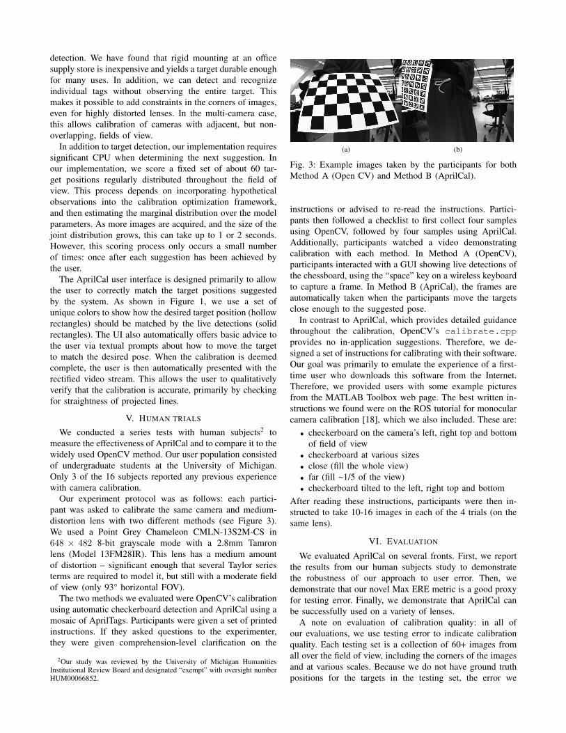
(a) (b)
Fig. 3: Example images taken by the participants for both
Method A (Open CV) and Method B (AprilCal).
instructions or advised to re-read the instructions. Partici-
pants then followed a checklist to first collect four samples
using OpenCV, followed by four samples using AprilCal.
Additionally, participants watched a video demonstrating
calibration with each method. In Method A (OpenCV),
participants interacted with a GUI showing live detections of
the chessboard, using the “space” key on a wireless keyboard
to capture a frame. In Method B (ApriCal), the frames are
automatically taken when the participants move the targets
close enough to the suggested pose.
In contrast to AprilCal, which provides detailed guidance
throughout the calibration, OpenCV’s calibrate.cpp
provides no in-application suggestions. Therefore, we de-
signed a set of instructions for calibrating with their software.
Our goal was primarily to emulate the experience of a first-
time user who downloads this software from the Internet.
Therefore, we provided users with some example pictures
from the MATLAB Toolbox web page. The best written in-
structions we found were on the ROS tutorial for monocular
camera calibration [18], which we also included. These are:
• checkerboard on the camera’s left, right top and bottom
of field of view
• checkerboard at various sizes
• close (fill the whole view)
• far (fill ~1/5 of the view)
• checkerboard tilted to the left, right top and bottom
After reading these instructions, participants were then in-
structed to take 10-16 images in each of the 4 trials (on the
same lens).
VI. EVALUATION
We evaluated AprilCal on several fronts. First, we report
the results from our human subjects study to demonstrate
the robustness of our approach to user error. Then, we
demonstrate that our novel Max ERE metric is a good proxy
for testing error. Finally, we demonstrate that AprilCal can
be successfully used on a variety of lenses.
A note on evaluation of calibration quality: in all of
our evaluations, we use testing error to indicate calibration
quality. Each testing set is a collection of 60+ images from
all over the field of view, including the corners of the images
and at various scales. Because we do not have ground truth
positions for the targets in the testing set, the error we

Dataset Lens Model Reprojection Error
Mean Max
OpenCV Radial, 3 distortion terms 0.728 38.646AprilCal Radial, 3 distortion terms 0.229 1.651AprilCal Angular, 4 distortion terms 0.203 1.444
TABLE I: Mean and max testing errors averaged over all
human subject trials in comparison to a 65 image reference
dataset for the same lens. Results are significant with p <
6.3 × 10⁻⁷ for both mean and max errors and all pairs of
rows.
report is after we optimize the target extrinsics to best fit the
fixed model parameters for a given calibration. While this
in general results in lower reprojection errors, it ensures that
all models are fairly evaluated and still allows discrimination
between good and bad calibrations.
Furthermore, Mean Reprojection Error (MRE) is typically
reported as a summary of calibration quality, as it is simple to
understand and robust to detector error. However, it can also
often mask systematic errors in the underlying calibration.
Therefore, we also report Max Reprojection Error on the
test set – this ensures that calibrations are evaluated by their
performance everywhere in the image.
A. Novice Calibrators using AprilCal and OpenCV
Our study results show that novices do a significantly
better job calibrating when using AprilCal than when using
OpenCV (p < 6.3 × 10⁻⁷). For example, with testing
set errors averaged over all participants, the testing MRE
using OpenCV is approximately three times that when using
AprilCal (see Table I). The disparity is even greater when
considering the Max Reprojection Errors – OpenCV aver-
ages 38 pixels (6% of the image), whereas AprilCal averages
a much lower 1.6 pixels for the same model. Interestingly,
no OpenCV calibration yielded a max reprojection error
better than the worst max reprojection error from AprilCal
(2.02 pixels). This may be because the sorts of images that
novice users capture, even when attempting to follow the
ROS instructions, don’t constrain the whole lens well. With
the target suggestions provided by AprilCal, even new users
of camera calibration software can produce calibrations with
very low worst-case reprojection errors. The error histograms
for both populations is shown in Figure 4.
The human study results can also help us understand where
in the image the calibrations disagree. Figure 6 depicts the
expected error between the human trials and a 65 image
reference calibration. From the images shown, it is clear that
the OpenCV calibrations fail to capture the lens model in
the image corners. This can be explained by both the need
to observe the whole calibration target in OpenCV and the
difficulty for users to predict where constraints are needed.
In addition to showing that AprilCal calibrations are more
accurate, the user study results also show that calibrations
with AprilCal are more consistent. Figure 5 depicts the dis-
tribution of focal lengths and focal centers for both AprilCal
and OpenCV. While both distributions have similar means,
Fig. 4: Mean and Max Reprojection Errors (on a 65-
image test set) for calibrations produced using AprilCal
and OpenCV. Users produced significantly more reliable
calibrations using the proposed method (p < 6.3 × 10⁻⁷).
For OpenCV, 3 MREs and 46 MaxREs not visible within
plot extents.
Dataset Focal length (x) Focal center (x)
Mean Std dev Mean Std dev
OpenCV 378.9† 9.0† 327.8† 1.9†
AprilCal 381.7 1.2 328.0 0.8
Fig. 5: Distribution of focal lengths and focal centers for all
trials in the human study. While the mean parameter values
from calibrations with AprilCal and OpenCV are similar, the
standard deviations for the OpenCV calibrations are much
higher. †One OpenCV outlier that would have further skewed
the calculations was omitted from the calculations and is not
visible within the plot extents. Best viewed in color.
the AprilCal standard deviations are 7.5× smaller for focal
lengths and 2.37× smaller for focal centers.
B. Evaluating the Max ERE metric
We designed the Max ERE to be a good measure of
calibration quality. Specifically, we want users to specify
the accuracy they need for their application (e.g. < 1 px),
and if the Max ERE falls below that threshold, then the
calibration can confidently be said to be that accurate. To
validate these claims, we computed several variants of testing
error over a large number of AprilCal trials. After each
image is added, we evaluate the performance using Max
ERE, as well as on an independent testing set using Max
(100th percentile), 99.5th percentile, and mean reprojection
errors. As can be seen in Figure 7, our sampled-MRE metric
corresponds closely to the highest percentiles of testing error.
This shows empirical evidence that our metric is effective.
C. Accuracy of AprilCal on a Variety of Lenses
In addition to performing reliably for a wide range of
users, AprilCal also produces accurate calibrations for a

(a) OpenCV (Radial, 3 dist. terms) (b) AprilCal (Radial, 3 dist. terms)
(d) Cross section from the focal center to the furthest corner in the image
Fig. 6: Heatmaps and cross section depicting per-pixel mean
reprojection error between test subject calibrations and a 65
image testing set. Reprojection errors were calculated by
projecting a point for every pixel in the reference calibration
through all test subject calibrations, then computing the
pixel distance. The reference calibration used an angular
polynomial model with 4 terms, as it had the lowest mean
and max training errors. AprilCal calibrations show low error
in all parts of the image, while OpenCV calibrations have
very high error in the corners (see arrow).
number of camera and lens configurations. Each lens was
calibrated multiple times by one of the authors using the
guidance provided by AprilCal (typically requiring 6-8 im-
ages in total). A separate 60+ image testing set was collected
to evaluate the accuracy for each configuration. To fairly
compare results from different lenses, we compute each lens’
testing error against a reference calibration computed from
the corresponding test set. This eliminates the effects of
detector error on testing error, which varies for different
images sizes (See Eqn 12). For each target point detected
in the testing set, we project through both the reference
calibration and the calibration using AprilCal, and compute
the Mean, 99.5th percentile and Max Reprojections Errors.
Figure 8 shows the testing error for six configurations that
our lab uses for various robotics applications, including
stereo odometry, object detection and overhead ground truth.
In each case, the testing MRE is significantly below one
pixel. Example images from each configuration are shown
in Figure 9.
VII. SUMMARY
AprilCal is an interactive calibration tool that provides
live feedback on the state of the calibration and produces
tightly-distributed calibration parameters even when used by
3 4 5 6 7 8
0.0
0.5
1.0
1.5
2.0
2.5
3.0
Num. Images
Err
or
(pix
els)
Testing Max−REMax ERETesting 99.5%−tileTesting MRE
Fig. 7: Our novel Max Expected Reprojection Error (Max
ERE) metric (red) correlates highly with the 99.5th percentile
of reprojection errors on an independently captured test set.
The Max ERE allows us to automatically compute a rigorous
accuracy score for a partial calibration without needing an
exhaustive test set. Error bars reflect std. error of the mean.
(A) (B) (C) (D) (E) (F)
0.0
0.5
1.0
1.5 Testing MRETesting 99.5%−tileTesting Max−RE
Lens DFOV Resolution Format
(a) Fujinon YV2.2x1.4A-2 143◦ 648× 482 Gray(b) Tamron 13FM22IR 146◦ 648× 482 Gray(c) Tamron 13FM28IR 114◦ 648× 482 Gray(d) Boowon BW38B 83◦ 752× 480 Color(e) Boowon BW3M30B 121◦ 648× 482 Gray(f) Boowon BW3M30B 121◦ 1296× 964 Color
Fig. 8: Testing error for a variety of camera configurations
using AprilCal. The Diagonal Field Of View (DFOV) was
estimated from the testing sets for each configuration. Error
bars reflect std. error of the mean.
novices. We have leveraged a novel calibration quality metric
(Max ERE) to automatically determine whether a calibration
is sufficiently accurate, without requiring a user to collect
a rigorous testing set. We conducted a 16-person human
subjects study to show that even novice users can produce
consistent, quality calibrations using such a system.
We have evaluated AprilCal in a variety of ways, and
demonstrated that it is a suitable replacement for the cur-
rently available calibration toolkits, which use a batch cal-
ibration process and training error as a quality metric. Our
desire is to make accurate camera calibration available to a
wider audience who can use the resulting model parameters
confidently in a range of applications.

(a) Fujinon YV2.2x1.4A-2 (648× 482) (b) Tamron 13FM22IR (648× 482) (c) Tamron 13FM28IR (648× 482)
(d) Boowon BW38B (752× 480) (e) Boowon BW3M30B (648× 482) (f) Boowon BW3M30B (1296× 964)
Fig. 9: Example images for each of the configurations evaluated in Figure 8. These lenses are representative of those known
to work with AprilCal. Image contrast adjusted for clarity.
ACKNOWLEDGMENTS
This work was funded by U.S. DoD Grant FA2386-11-1-
4024.
REFERENCES
[1] J. Barreto and K. Daniilidis. Wide area multiple camera calibrationand estimation of radial distortion. In Omnivis-2004, ECCV-2004
workshop, 2004.[2] J. Barreto, J. Roquette, P. Sturm, F. Fonseca, et al. Automatic camera
calibration applied to medical endoscopy. In 20th British Machine
Vision Conference (BMVC’09), 2009.[3] J.-Y. Bouguet. Camera calibration toolbox for MATLAB, July 2010.[4] G. Bradski. The OpenCV Library. Dr. Dobb’s Journal of Software
Tools, 2000.[5] F. Dellaert and M. Kaess. Square root SAM: Simultaneous localization
and mapping via square root information smoothing. International
Journal of Robotics Research, 25(12):1181–1203, December 2006.[6] F. Devernay and O. Faugeras. Straight lines have to be straight.
Machine Vision and Applications, 13(1):14–24, 2001.[7] D. Forsyth and J. Ponce. Computer Vision: A Modern Approach.
Prentice Hall Professional Technical Reference, 2002.[8] A. Geiger, J. Ziegler, and C. Stiller. StereoScan: Dense 3d reconstruc-
tion in real-time. In IEEE Intelligent Vehicles Symposium, Baden-Baden, Germany, June 2011.
[9] R. Hartley and A. Zisserman. Multiple View Geometry in Computer
Vision. Cambridge University Press, second edition, 2004.[10] J. Kannala and S. S. Brandt. A generic camera model and cal-
ibration method for conventional, wide-angle, and fish-eye lenses.Pattern Analysis and Machine Intelligence, IEEE Transactions on,28(8):1335–1340, 2006.
[11] K. Konolige. Sparse sparse bundle adjustment. In British Machine
Vision Conference, Aberystwyth, Wales, August 2010.
[12] R. Kummerle, G. Grisetti, H. Strasdat, K. Konolige, and W. Burgard.g2o: A general framework for graph optimization. In ICRA, Shanghai,May 2011.
[13] M. Li. Camera calibration of a head-eye system for active vision.Computer VisionECCV’94, pages 541–554, 1994.
[14] C. Mei, G. Sibley, M. Cummins, P. Newman, and I. Reid. RSLAM:A system for large-scale mapping in constant-time using stereo.International Journal of Computer Vision, pages 1–17, 2010.
[15] R. A. Newcombe and A. J. Davison. Live dense reconstruction witha single moving camera. In Computer Vision and Pattern Recognition
(CVPR), 2010 IEEE Conference on, pages 1498–1505. IEEE, 2010.[16] E. Olson. AprilTag: A robust and flexible visual fiducial system. In
Proceedings of the IEEE International Conference on Robotics and
Automation (ICRA), May 2011.[17] V. Pradeep, K. Konolige, and E. Berger. Calibrating a multi-arm
multi-sensor robot: A bundle adjustment approach. In International
Symposium on Experimental Robotics (ISER), New Delhi, India,12/2010 2010.
[18] M. Quigley, B. Gerkey, K. Conley, J. Faust, T. Foote, J. Leibs,E. Berger, R. Wheeler, and A. Ng. Ros: an open-source robot operatingsystem. In ICRA workshop on open source software, volume 3, 2009.
[19] P. Ranganathan and E. Olson. Gaussian process for lens distortionmodeling. In Proceedings of the IEEE/RSJ International Conference
on Intelligent Robots and Systems (IROS), October 2012.[20] J. Strom, A. Richardson, and E. Olson. Graph-based segmentation
for colored 3D laser point clouds. In Proceedings of the IEEE/RSJ
International Conference on Intelligent Robots and Systems (IROS),October 2010.
[21] T. Svoboda. A software for complete calibration of multicamerasystems. In Electronic Imaging 2005, pages 115–128. InternationalSociety for Optics and Photonics, 2005.
[22] Z. Zhang. A flexible new technique for camera calibration.IEEE Transactions on Pattern Analysis and Machine Intelligence,22(11):1330–1334, 2000.

![s460fd84d65ef8adb.jimcontent.com · Web view2013年10月1日JIMDO.docxMicrosoftワード文書 [1.6 MB] ダウンロード 13年9月本文他.docxMicrosoftワード文書 [4.7 MB]](https://img.pdfslide.net/doc/110x75/603c40e8c53f675b09771c03/web-view-201310oe1jimdodocxmicrosoftfff-16-mb-fffff.jpg)


![PDF[1.6 MB/16ページ]](https://img.pdfslide.net/doc/110x75/5892fc881a28ab60308bc72c/pdf16-mb16.jpg)