Embed Size (px)
Citation preview

2410CCD/CCDW Computer AlignerService Manual
M 0587 000 - �
M
GB
Operating instructions
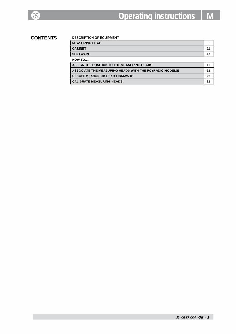
CONTENTS DESCRIPTION OF EQUIPMENTMEASURING HEAD 3CABINET 11SOFTWARE 17HOW TO....ASSIGN THE POSITION TO THE MEASURING HEADS 19ASSOCIATE THE MEASURING HEADS WITH THE PC (RADIO MODELS) 21UPDATE MEASURING HEAD FIRMWARE 27CALIBRATE MEASURING HEADS 29

M 0587 000 - � GB
M 0587 - �
M
Measuring head GB
Description of equipment1.1 - MEASURING HEAD
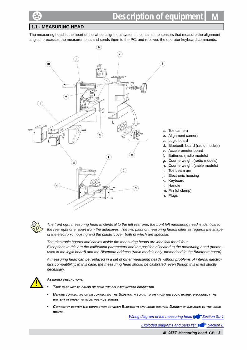
The measuring head is the heart of the wheel alignment system: it contains the sensors that measure the alignment angles, processes the measurements and sends them to the PC, and receives the operator keyboard commands.
a. Toe camerab. Alignment camerac. Logic boardd. Bluetooth board (radio models)e. Accelerometer boardf. Batteries (radio models)g. Counterweight (radio models)h. Counterweight (cable models)i. Toe beam armj. Electronic housingk. Keyboardl. Handlem. Pin (of clamp)n. Plugs
The front right measuring head is identical to the left rear one; the front left measuring head is identical to the rear right one, apart from the adhesives. The two pairs of measuring heads differ as regards the shape of the electronic housing and the plastic cover, both of which are specular.
The electronic boards and cables inside the measuring heads are identical for all four. Exceptions to this are the calibration parameters and the position allocated to the measuring head (memo-rised in the logic board) and the Bluetooth address (radio models only, memorised in the Bluetooth board)
A measuring head can be replaced in a set of other measuring heads without problems of internal electro-nics compatibility. In this case, the measuring head should be calibrated, even though this is not strictly necessary.
Assembly precAutions:
tAke cAre not to crush or bend the delicAte keypAd connector
before connecting or disconnecting the bluetooth boArd to or from the logic boArd, disconnect the bAttery in order to Avoid voltAge surges.
correctly center the connection between bluetooth And logic boArds! dAnger of dAmAges to the logic boArd.
Wiring diagram of the measuring head Section Sb-1
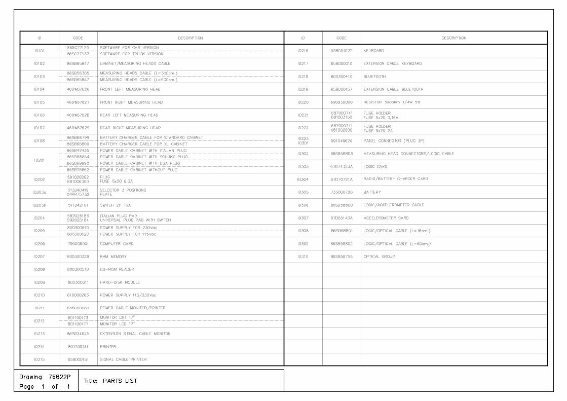
Exploded diagrams and parts list Section E
▪
▪
▪
M 0587 - �
T (+)
A(+)
L (+)
Z
C (+)
Measuring head GB
Measurements
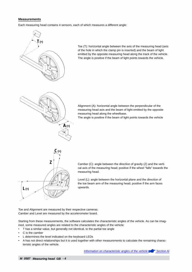
Each measuring head contains 4 sensors, each of which measures a different angle:
Toe (T): horizontal angle between the axis of the measuring head (axis of the hole in which the clamp pin is inserted) and the beam of light emitted by the opposite measuring head along the track of the vehicle.The angle is positive if the beam of light points towards the vehicle.
Alignment (A): horizontal angle between the perpendicular of the measuring head axis and the beam of light emitted by the opposite measuring head along the wheelbase.The angle is positive if the beam of light points towards the vehicle
Camber (C): angle between the direction of gravity (Z) and the verti-cal axis of the measuring head; positive if the wheel “falls” towards the measuring head.
Level (L): angle between the horizontal plane and the direction of the toe beam arm of the measuring head; positive if the arm faces upwards.
Toe and Alignment are measured by their respective cameras. Camber and Level are measured by the accelerometer board.
Starting from these measurements, the software calculates the characteristic angles of the vehicle. As can be imag-ined, some measured angles are related to the characteristic angles of the vehicle:
T has a similar value, but generally not identical, to the partial toe angleC is the camberL determines the level indicated on the keyboard LEDsA has not direct relationships but it is used together with other measurements to calculate the remaining charac-teristic angles of the vehicle.
Information on characteristic angles of the vehicle Section Ai
▪▪▪▪
M 0587 - 5
CCDLED
Measuring head GB
Calibration parameters
The calibration parameters are used to convert the electrical signals from the sensors into the corresponding angles. 8 parameters, the Zero and Gain of each of the 4 sensors of the measuring head, are stored in the logic board.
The electrical signals of the sensors are converted using a proportional formula:
Angle = Gain x Signal + Zero
Zeros can be calibrated on site by means of a special calibration bar, while Gains can only be factory set. Gains are generally calibrated just once during in the lifetime of a sensor because, unless the components are faulty, Gains remain stable over time and, in any case, affect precision much less than the Zeros.
In the following, "Calibrating the measuring heads" will have to be intended as calibrating the Zeros only, by mean of the calibration bar.
Calibrating the measuring heads M - 2.5
Cameras
There are two cameras:Toe: along the trackAlignment : along the wheelbase
The toe and alignment cameras are identical and are therefore interchangeable.
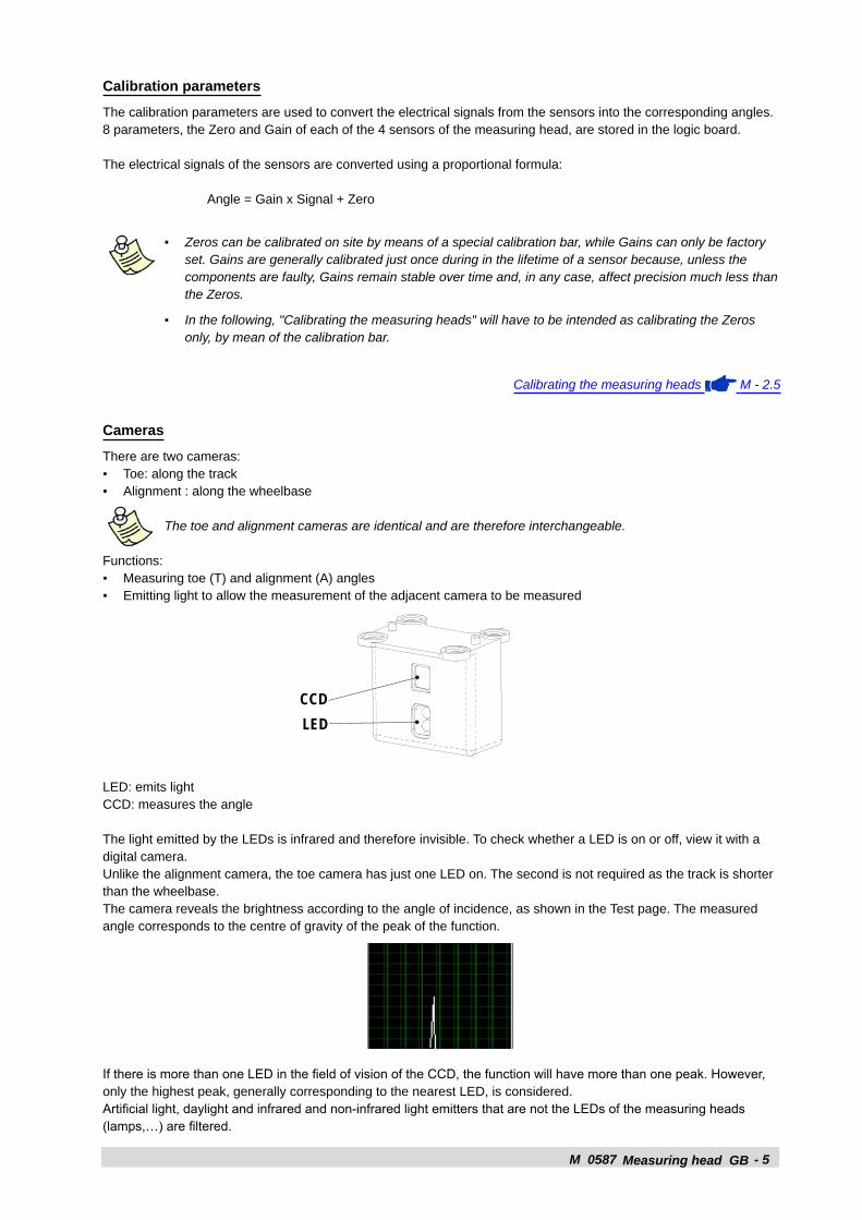
Functions:Measuring toe (T) and alignment (A) anglesEmitting light to allow the measurement of the adjacent camera to be measured
LED: emits lightCCD: measures the angle
The light emitted by the LEDs is infrared and therefore invisible. To check whether a LED is on or off, view it with a digital camera.Unlike the alignment camera, the toe camera has just one LED on. The second is not required as the track is shorter than the wheelbase.The camera reveals the brightness according to the angle of incidence, as shown in the Test page. The measured angle corresponds to the centre of gravity of the peak of the function.
If there is more than one LED in the field of vision of the CCD, the function will have more than one peak. However, only the highest peak, generally corresponding to the nearest LED, is considered. Artificial light, daylight and infrared and non-infrared light emitters that are not the LEDs of the measuring heads (lamps,…) are filtered.
▪
▪
▪▪
▪▪
M 0587 - �
c b d
g h ak i
e
f
j
Measuring head GB
A non-faulty camera can give problems in the following rare cases:
Direct sunlight “blinds” the CCD. Measurement not performed. Put the CCD in the shade.
The camera beam is reflected by the bodywork of the vehicle or by a highly reflective metal panel. Brightness vs. angle has more than one peak. Cover the surface with a cloth.
Two lifts are side by side so that the toe CCD frames the toe LED of the other lift. Brightness vs. angle has more than one peak. Separate the lifts with a panel.
If a camera is replaced its Zero must be calibrated.
Software M - 1.3
Calibrating the measuring heads M - 2.5
Logic Board
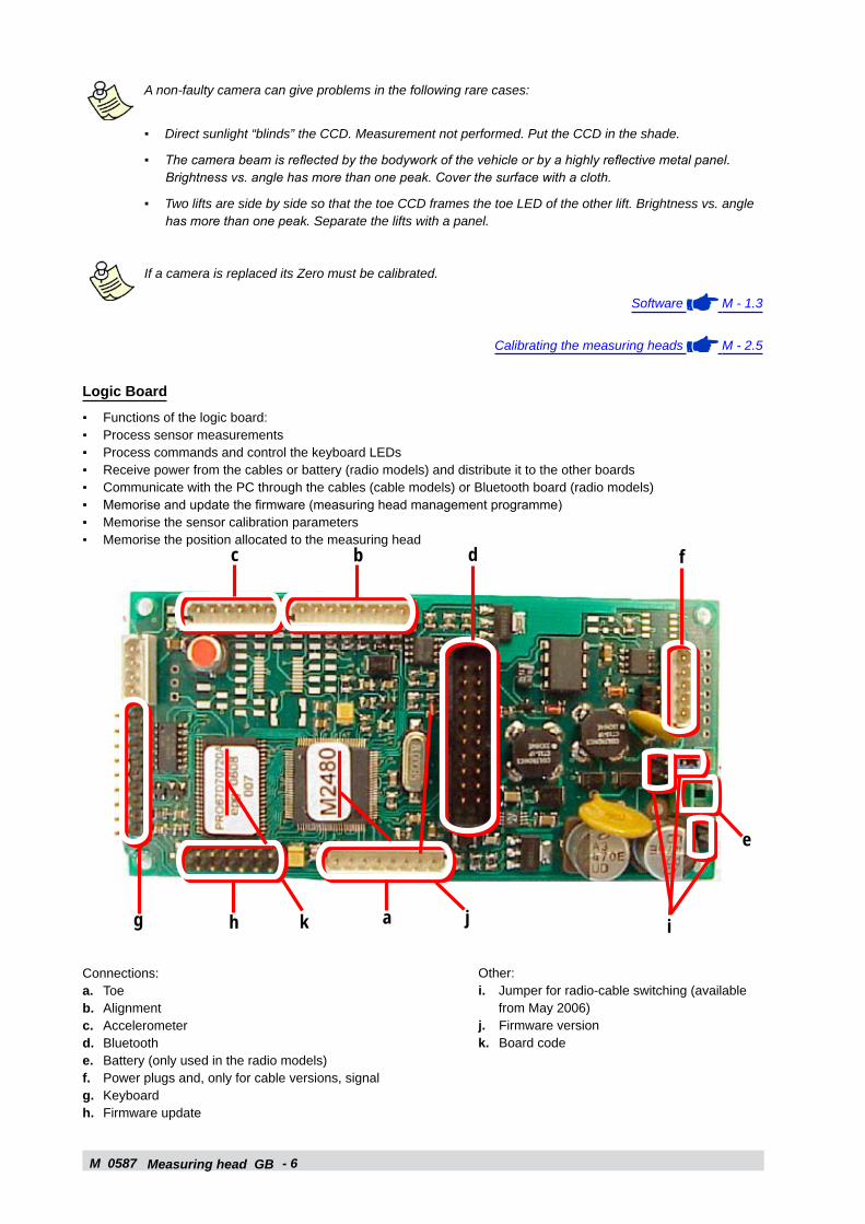
Functions of the logic board:Process sensor measurementsProcess commands and control the keyboard LEDsReceive power from the cables or battery (radio models) and distribute it to the other boardsCommunicate with the PC through the cables (cable models) or Bluetooth board (radio models)Memorise and update the firmware (measuring head management programme)Memorise the sensor calibration parametersMemorise the position allocated to the measuring head
▪
▪
▪
▪▪▪▪▪▪▪▪
Connections:a. Toeb. Alignmentc. Accelerometerd. Bluetoothe. Battery (only used in the radio models)f. Power plugs and, only for cable versions, signalg. Keyboardh. Firmware update
Other:i. Jumper for radio-cable switching (available
from May 2006)j. Firmware versionk. Board code
M 0587 - 7Measuring head GB
The silver bands on the keyboard connector must face towards the outside of the board, as shown in the figure:
The radio measuring heads only communicate with the PC via Bluetooth, even when the cables are connected. The brown wire connecting the logic board to the plugs is not used.The firmware controls the operation of the measuring head. The firmware version is called in two different but equiva-lent ways in the Test page and on the logic board. For example, the “2.F” version in the Test page is the same as “M2846” on the logic board. The logic boards of the radio and cable models are identical as regards hardware. It is therefore possible to convert a logic board configured for cable models into a board configured for radio models and vice-versa (apart from logic board 67D58965A which is only for cable models).
When replacing the logic board:
it is possible to maintain the existing cameras but the accelerometer board must be replaced (the Gains of the various cameras are sufficiently similar, while those of the various accelerometers are not)
the Zeros must be calibrated and the position of the measuring head allocated.
Logic board modification logProduction start date
Production start measuring head
Code (Version)
Modifications Notes
December 2004
67D58905A Initial version Only with accelerometer board 67D58906A (yellow stamp)
February 2005 00001C, 00001R 67D65142A67D65142B
New accelerometer supportBoth cable (…A) and radio (…B) models
Only with accelerometer board 67D65143A (blue stamp)Hardware identical for cable and radio models. Firmware differentDefect: the radio does not connect if the cables are connected at start-upNo automatic start-up when the cables are connected
June 2006 00813C, 01245R 67D70720A Firmware identical for cable and radioConnects radio if cables are connected at start-up
Cable or radio settings via jumper (i)Cable: J5, J7 closed, J6 open (a)Radio: J6 closed, J5, J7 open (b)
(a) (b)
July 2006 01449R 67D70720A (R.2)
Added welded diode for automatic start-up when the cables are connected
July 2006 67D70720A (R.3)
No longer necessary to close J5 to set cable (in any case, it does not matter if it closes)
October 2006 01133C, 01985R 67D74363A Previously welded diode integrated
Calibrating the measuring heads M - 2.5
Allocating the position to the measuring heads M - 2.1
How to update the measuring head firmware M - 2.4
▪
▪
M 0587 - 8Measuring head GB
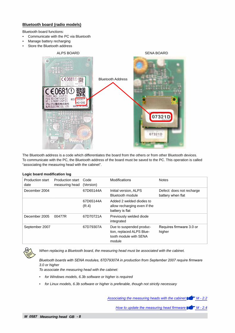
Bluetooth board (radio models)
Bluetooth board functions:Communicate with the PC via BluetoothManage battery rechargingStore the Bluetooth address
The Bluetooth address is a code which differentiates the board from the others or from other Bluetooth devices. To communicate with the PC, the Bluetooth address of the board must be saved to the PC. This operation is called “associating the measuring head with the cabinet”.
Logic board modification logProduction start date
Production start measuring head
Code (Version)
Modifications Notes
December 2004 67D65144A Initial version, ALPS Bluetooth module
Defect: does not recharge battery when flat
67D65144A (R.4)
Added 2 welded diodes to allow recharging even if the battery is flat
December 2005 00477R 67D70721A Previously welded diode integrated
September 2007 67D79307A Due to suspended produc-tion, replaced ALPS Blue-tooth module with SENA module
Requires firmware 3.0 or higher
When replacing a Bluetooth board, the measuring head must be associated with the cabinet.
Bluetooth boards with SENA modules, 67D79307A in production from September 2007 require firmware 3.0 or higherTo associate the measuring head with the cabinet:
for Windows models, 6.3b software or higher is required
for Linux models, 6.3b software or higher is preferable, though not strictly necessary
Associating the measuring heads with the cabinet M - 2.2
How to update the measuring head firmware M - 2.4
▪▪▪
▪
▪
Bluetooth Address
ALPS BOARD SENA BOARD
M 0587 - �Measuring head GB
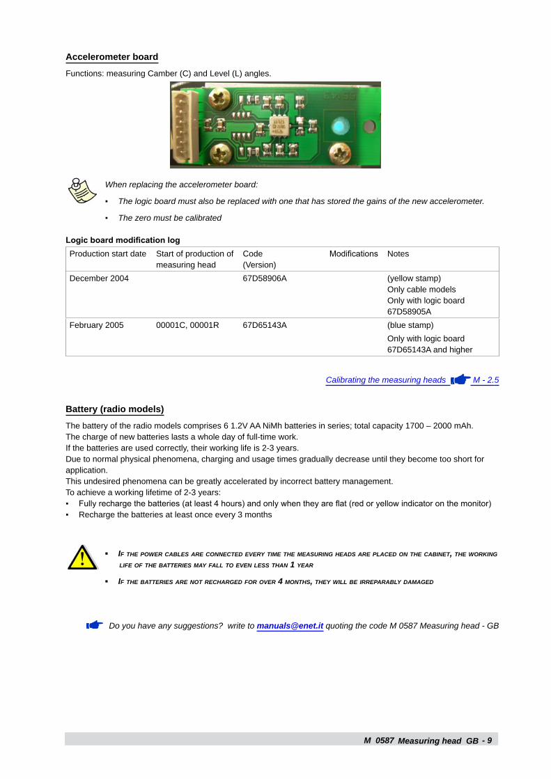
Accelerometer board
Functions: measuring Camber (C) and Level (L) angles.
When replacing the accelerometer board:
The logic board must also be replaced with one that has stored the gains of the new accelerometer.
The zero must be calibrated
Logic board modification logProduction start date Start of production of
measuring headCode (Version)
Modifications Notes
December 2004 67D58906A (yellow stamp)Only cable modelsOnly with logic board 67D58905A
February 2005 00001C, 00001R 67D65143A (blue stamp)Only with logic board 67D65143A and higher
Calibrating the measuring heads M - 2.5
Battery (radio models)
The battery of the radio models comprises 6 1.2V AA NiMh batteries in series; total capacity 1700 – 2000 mAh.The charge of new batteries lasts a whole day of full-time work. If the batteries are used correctly, their working life is 2-3 years.Due to normal physical phenomena, charging and usage times gradually decrease until they become too short for application. This undesired phenomena can be greatly accelerated by incorrect battery management.To achieve a working lifetime of 2-3 years:
Fully recharge the batteries (at least 4 hours) and only when they are flat (red or yellow indicator on the monitor)Recharge the batteries at least once every 3 months
if the power cAbles Are connected every time the meAsuring heAds Are plAced on the cAbinet, the working life of the bAtteries mAy fAll to even less thAn 1 yeAr
if the bAtteries Are not rechArged for over 4 months, they will be irrepArAbly dAmAged
Do you have any suggestions? write to [email protected] quoting the code M 0587 Measuring head - GB
▪
▪
▪▪
▪
▪

M 0587 - 10Measuring head GB
M 0587 - 11
M
Cabinet GB
1.2 - CABINET
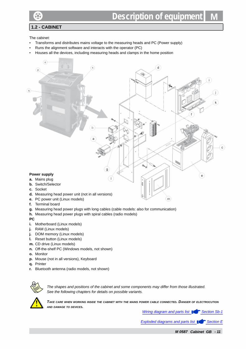
The cabinet: Transforms and distributes mains voltage to the measuring heads and PC (Power supply)Runs the alignment software and interacts with the operator (PC)Houses all the devices, including measuring heads and clamps in the home position
Power supply a. Mains plugb. Switch/Selectorc. Socketd. Measuring head power unit (not in all versions)e. PC power unit (Linux models)f. Terminal boardg. Measuring head power plugs with long cables (cable models: also for communication)h. Measuring head power plugs with spiral cables (radio models)PC i. Motherboard (Linux models)j. RAM (Linux models)j. DOM memory (Linux models)l. Reset button (Linux models)m. CD drive (Linux models)n. Off-the-shelf PC (Windows models, not shown) o. Monitorp. Mouse (not in all versions), Keyboardq. Printerr. Bluetooth antenna (radio models, not shown)
The shapes and positions of the cabinet and some components may differ from those illustrated. See the following chapters for details on possible variants.
tAke cAre when working inside the cAbinet with the mAins power cAble connected. dAnger of electrocution And dAmAge to devices.
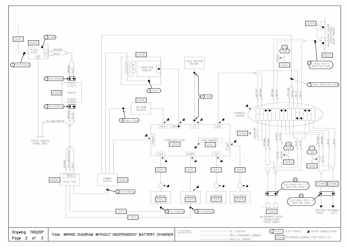
Wiring diagram and parts list Section Sb-1
Exploded diagrams and parts list Section E
▪▪▪
Description of equipment
M 0587 - 12Cabinet GB
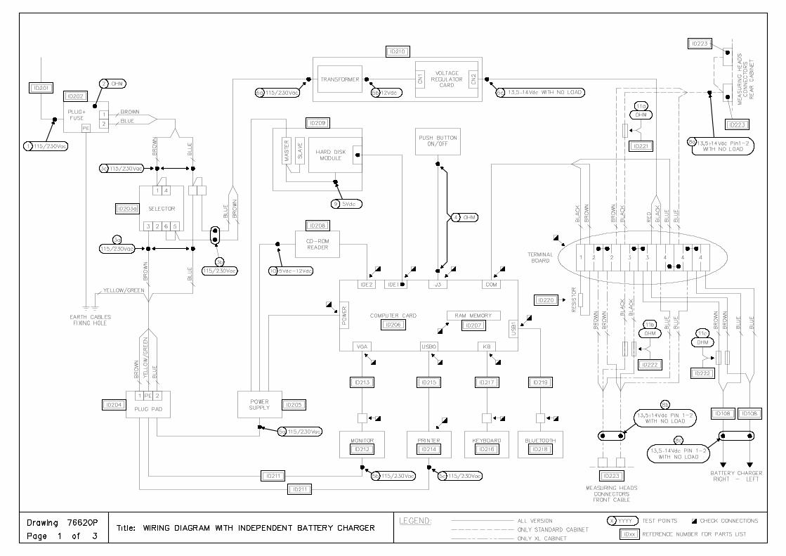
Power supply
Transforms and distributes mains voltage to the measuring heads and PC. It is described starting from the mains power socket and ending at the devices. The wiring diagram should be kept close at hand.
Mains plug
Receives mains power (115-230Vac) and sends it to the switch/selector.Houses 2 fuses
Switch/selector
Opens or closes the power supply to the PC and measuring heads. Version Models Positions Distributes to2-way switch ▪ Linux Cable
▪ Linux Radio until September 2006
(0) Off(1) Power to PC and measuring heads
Socket
3-way switch ▪ Linux Radio from September 2006
▪ Windows
(0) Off(1) Power to PC and measuring heads(2) Power to measuring heads only (used by radio models to recharge the batteries when the computer is switched off. Not used in Windows Cable models)
Socket
Measuring head power unit
Socket
Receives the power supply and distributes it to the PC power unit, the monitor and the printer.
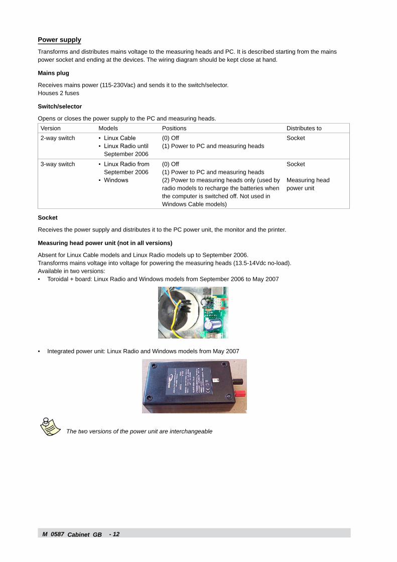
Measuring head power unit (not in all versions)
Absent for Linux Cable models and Linux Radio models up to September 2006.Transforms mains voltage into voltage for powering the measuring heads (13.5-14Vdc no-load).Available in two versions:
Toroidal + board: Linux Radio and Windows models from September 2006 to May 2007
Integrated power unit: Linux Radio and Windows models from May 2007
The two versions of the power unit are interchangeable
▪
▪
M 0587 - 1�Cabinet GB
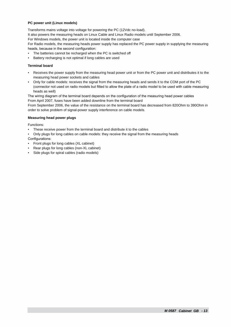
PC power unit (Linux models)
Transforms mains voltage into voltage for powering the PC (12Vdc no-load).It also powers the measuring heads on Linux Cable and Linux Radio models until September 2006.For Windows models, the power unit is located inside the computer caseFor Radio models, the measuring heads power supply has replaced the PC power supply in supplying the measuring heads, because in the second configuration:
The batteries cannot be recharged when the PC is switched offBattery recharging is not optimal if long cables are used
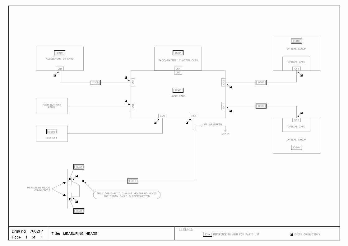
Terminal board
Receives the power supply from the measuring head power unit or from the PC power unit and distributes it to the measuring head power sockets and cablesOnly for cable models: receives the signal from the measuring heads and sends it to the COM port of the PC (connector not used on radio models but fitted to allow the plate of a radio model to be used with cable measuring heads as well)
The wiring diagram of the terminal board depends on the configuration of the measuring head power cablesFrom April 2007, fuses have been added downline from the terminal boardFrom September 2006, the value of the resistance on the terminal board has decreased from 820Ohm to 390Ohm in order to solve problem of signal-power supply interference on cable models.
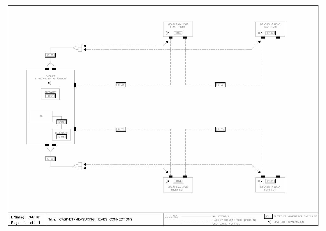
Measuring head power plugs
Functions:These receive power from the terminal board and distribute it to the cablesOnly plugs for long cables on cable models: they receive the signal from the measuring heads
Configurations:Front plugs for long cables (XL cabinet)Rear plugs for long cables (non-XL cabinet)Side plugs for spiral cables (radio models)
▪▪
▪
▪
▪▪
▪▪▪
M 0587 - 1�
c d e p
g
i jk
h
ba
i jk
h
b
a
c dep
g
EPIA 5000 EPIA 6000
Cabinet GB
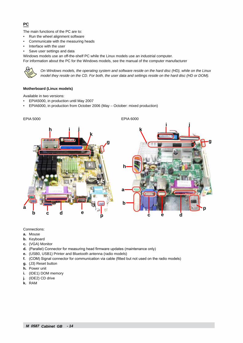
PC
The main functions of the PC are to:Run the wheel alignment softwareCommunicate with the measuring headsInterface with the userSave user settings and data
Windows models use an off-the-shelf PC while the Linux models use an industrial computer.For information about the PC for the Windows models, see the manual of the computer manufacturer
On Windows models, the operating system and software reside on the hard disc (HD), while on the Linux model they reside on the CD. For both, the user data and settings reside on the hard disc (HD or DOM).
Motherboard (Linux models)
Available in two versions:EPIA5000, in production until May 2007EPIA6000, in production from October 2006 (May – October: mixed production)
▪▪▪▪
▪▪
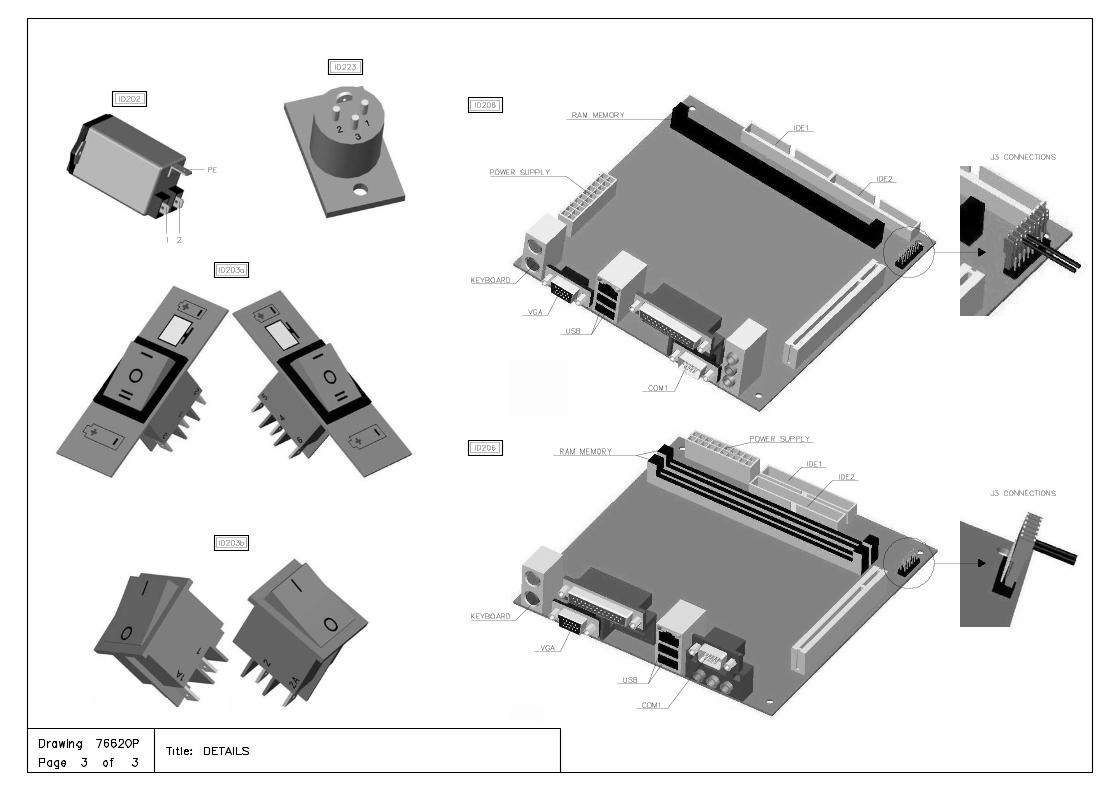
Connections:a. Mouseb. Keyboardc. (VGA) Monitord. (Parallel) Connector for measuring head firmware updates (maintenance only)e. (USB0, USB1) Printer and Bluetooth antenna (radio models)f. (COM) Signal connector for communication via cable (fitted but not used on the radio models)g. (J3) Reset buttonh. Power uniti. (IDE1) DOM memoryj. (IDE2) CD drivek. RAM
M 0587 - 15Cabinet GB
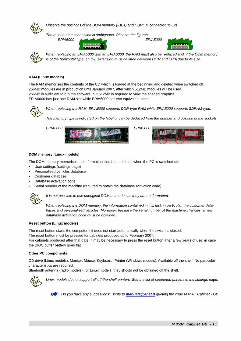
Observe the positions of the DOM memory (IDE1) and CDROM connector (IDE2)
The reset button connection is ambiguous. Observe the figures: EPIA6000 EPIA5000
When replacing an EPIA5000 with an EPIA6000, the RAM must also be replaced and, if the DOM memory is of the horizontal type, an IDE extension must be fitted between DOM and EPIA due to its size.
RAM (Linux models)
The RAM memorises the contents of the CD which is loaded at the beginning and deleted when switched off.256MB modules are in production until January 2007, after which 512MB modules will be used.256MB is sufficient to run the software, but 512MB is required to view the shaded graphicsEPIA6000 has just one RAM slot while EPIA5000 has two equivalent ones.
When replacing the RAM, EPIA6000 supports DDR-type RAM while EPIA5000 supports SDRAM-type.
The memory type is indicated on the label or can be deduced from the number and position of the sockets
EPIA6000 EPIA5000
DOM memory (Linux models)
The DOM memory memorises the information that is not deleted when the PC is switched off:User settings (settings page)Personalised vehicles databaseCustomer databaseDatabase activation codeSerial number of the machine (required to obtain the database activation code)
It is not possible to use unoriginal DOM memories as they are not formatted.
When replacing the DOM memory, the information contained in it is lost, in particular, the customer data-bases and personalised vehicles. Moreover, because the serial number of the machine changes, a new database activation code must be obtained.
Reset button (Linux models)
The reset button starts the computer if it does not start automatically when the switch is closed.The reset button must be pressed for cabinets produced up to February 2007.For cabinets produced after that date, it may be necessary to press the reset button after a few years of use, in case the BIOS buffer battery goes flat.
Other PC components
CD drive (Linux models), Monitor, Mouse, Keyboard, Printer (Windows models): Available off the shelf. No particular characteristics are required.Bluetooth antenna (radio models): for Linux models, they should not be obtained off the shelf.
Linux models do not support all off-the-shelf printers. See the list of supported printers in the settings page.
Do you have any suggestions? write to [email protected] quoting the code M 0587 Cabinet - GB
▪▪▪▪▪

M 0587 - 1�Cabinet GB
M 0587 Software - 17
a
b c d e f
g
h
i
j
k
l
M
GB
Description of equipment1.3 - SOFTWARE
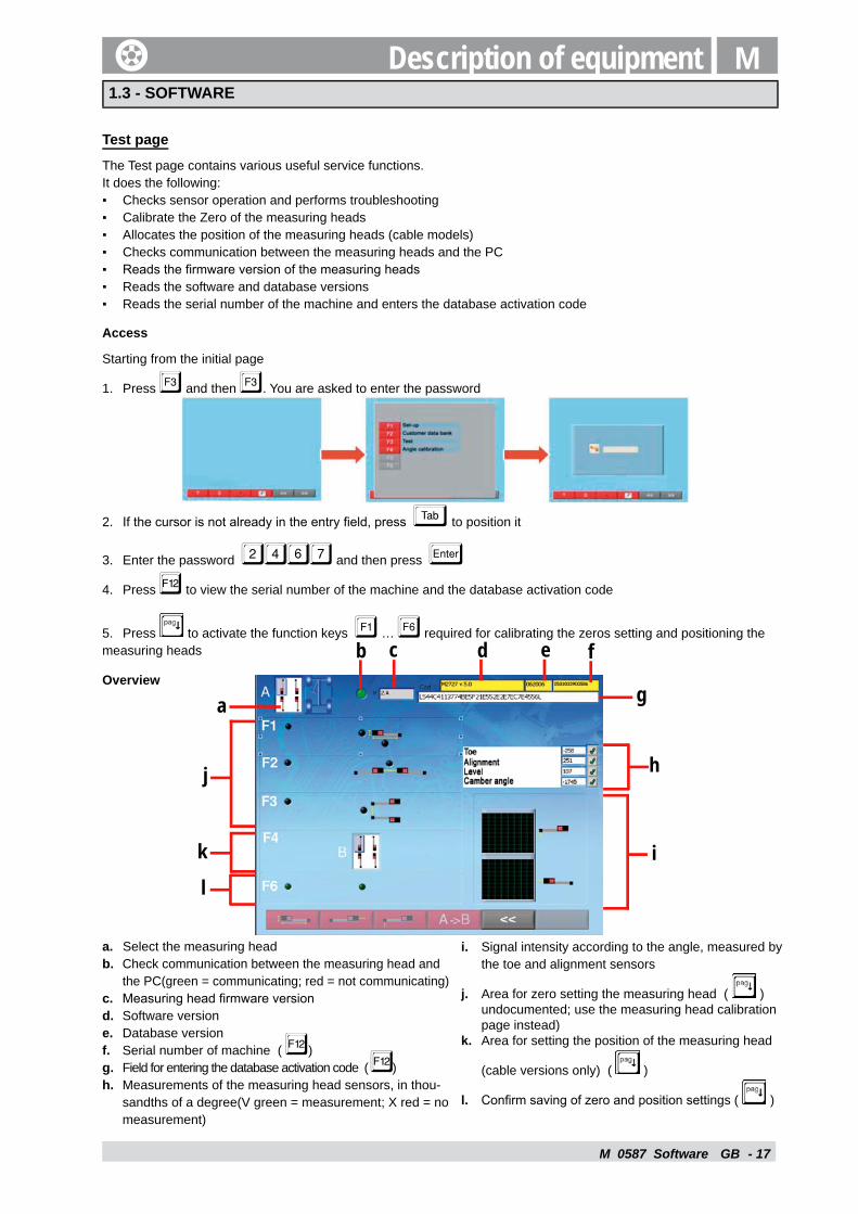
Test page
The Test page contains various useful service functions. It does the following:
Checks sensor operation and performs troubleshootingCalibrate the Zero of the measuring headsAllocates the position of the measuring heads (cable models)Checks communication between the measuring heads and the PCReads the fi rmware version of the measuring headsReads the software and database versionsReads the serial number of the machine and enters the database activation code
Access
Starting from the initial page
Press and then . You are asked to enter the password
If the cursor is not already in the entry fi eld, press © to position it
Enter the password 2467 and then press «Press to view the serial number of the machine and the database activation code
Press to activate the function keys � … � required for calibrating the zeros setting and positioning the measuring heads
Overview
▪▪▪▪▪▪▪
1.
2.
3.
4.
5.
a. Select the measuring headb. Check communication between the measuring head and
the PC(green = communicating; red = not communicating)c. Measuring head fi rmware versiond. Software versione. Database versionf. Serial number of machine ( )g. Field for entering the database activation code ( )h. Measurements of the measuring head sensors, in thou-
sandths of a degree(V green = measurement; X red = no measurement)
i. Signal intensity according to the angle, measured by the toe and alignment sensors
j. Area for zero setting the measuring head ( ) undocumented; use the measuring head calibration page instead)
k. Area for setting the position of the measuring head
(cable versions only) ( )
l. Confi rm saving of zero and position settings ( )
M 0587 Software - 18GB
The firmware version is called in two different but equivalent ways in the Test page and on the logic board. For example, the “2.F” version in the Test page is the same as “M2846” on the logic board.
Allocating the position to the measuring heads M - 2.2
Calibrating the measuring heads M - 2.6
Do you have any suggestions? write to [email protected] quoting the code M 0587 Software - GB
M 0587 - 1�
IM
Assign the position to the measuring heads GB
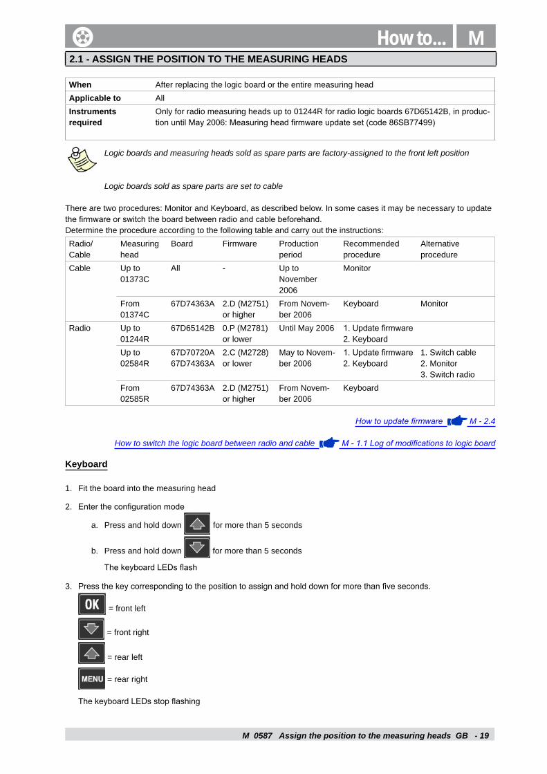
How to...2.1 - ASSIGN THE POSITION TO THE MEASURING HEADS
When After replacing the logic board or the entire measuring headApplicable to AllInstruments required
Only for radio measuring heads up to 01244R for radio logic boards 67D65142B, in produc-tion until May 2006: Measuring head firmware update set (code 86SB77499)
Logic boards and measuring heads sold as spare parts are factory-assigned to the front left position
Logic boards sold as spare parts are set to cable
There are two procedures: Monitor and Keyboard, as described below. In some cases it may be necessary to update the firmware or switch the board between radio and cable beforehand.Determine the procedure according to the following table and carry out the instructions:Radio/Cable
Measuring head
Board Firmware Production period
Recommended procedure
Alternative procedure
Cable Up to 01373C
All - Up toNovember 2006
Monitor
From 01374C
67D74363A 2.D (M2751) or higher
From Novem-ber 2006
Keyboard Monitor
Radio Up to01244R
67D65142B 0.P (M2781) or lower
Until May 2006 1. Update firmware2. Keyboard
Up to02584R
67D70720A67D74363A
2.C (M2728) or lower
May to Novem-ber 2006
1. Update firmware2. Keyboard
1. Switch cable2. Monitor3. Switch radio
From 02585R
67D74363A 2.D (M2751) or higher
From Novem-ber 2006
Keyboard
How to update firmware M - 2.4
How to switch the logic board between radio and cable M - 1.1 Log of modifications to logic board
Keyboard
Fit the board into the measuring head
Enter the configuration mode
Press and hold down for more than 5 seconds
Press and hold down for more than 5 seconds
The keyboard LEDs flash
Press the key corresponding to the position to assign and hold down for more than five seconds.
= front left
= front right
= rear left
= rear right
The keyboard LEDs stop flashing
1.
2.
a.
b.
3.
M 0587 - 20Assign the position to the measuring heads GB
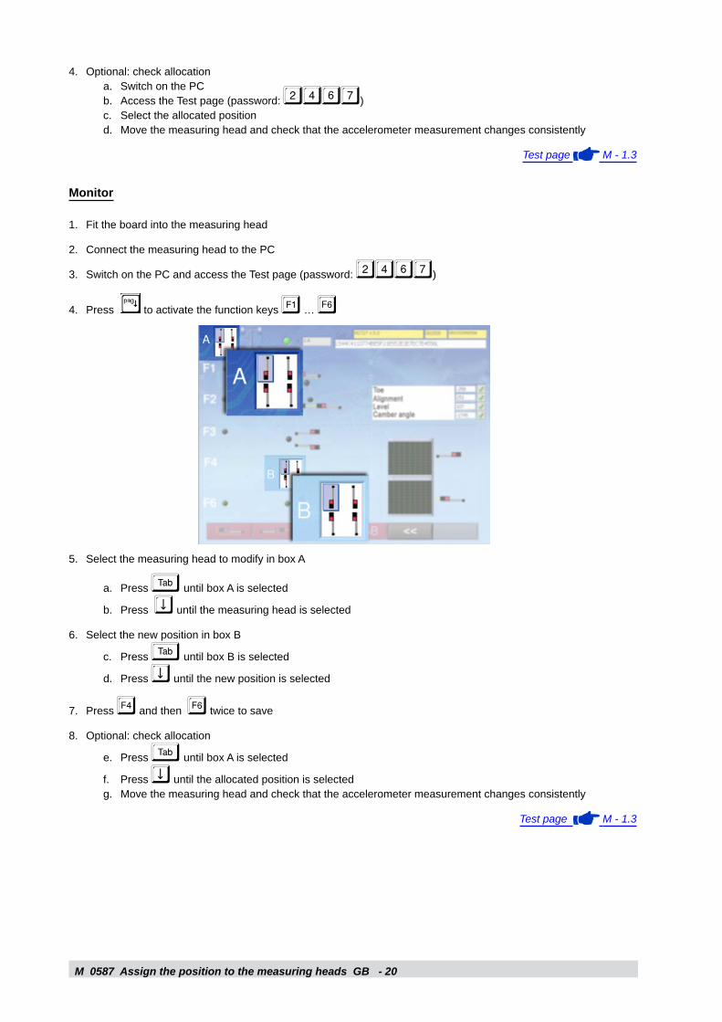
Optional: check allocationSwitch on the PCAccess the Test page (password: 2467)Select the allocated positionMove the measuring head and check that the accelerometer measurement changes consistently
Test page M - 1.3
Monitor
Fit the board into the measuring head
Connect the measuring head to the PC
Switch on the PC and access the Test page (password: 2467)
Press to activate the function keys � … �
Select the measuring head to modify in box A
Press © until box A is selected
Press ¢ until the measuring head is selected
Select the new position in box B
Press © until box B is selected
Press ¢ until the new position is selected
Press � and then � twice to save
Optional: check allocation
Press © until box A is selected
Press ¢ until the allocated position is selectedMove the measuring head and check that the accelerometer measurement changes consistently
Test page M - 1.3
4.a.b.c.d.
1.
2.
3.
4.
5.
a.
b.
6.
c.
d.
7.
8.
e.
f.g.
M 0587 Associate the measuring heads with the pc (radio models) - 21
M
GB
2.2 - ASSOCIATE THE MEASURING HEADS WITH THE PC (RADIO MODELS)
When After replacing the Bluetooth board or the entire radio measuring headApplicable to Radio models
The procedure differs for Linux and Windows models
Linux models
Switch on the PC. The following appears:
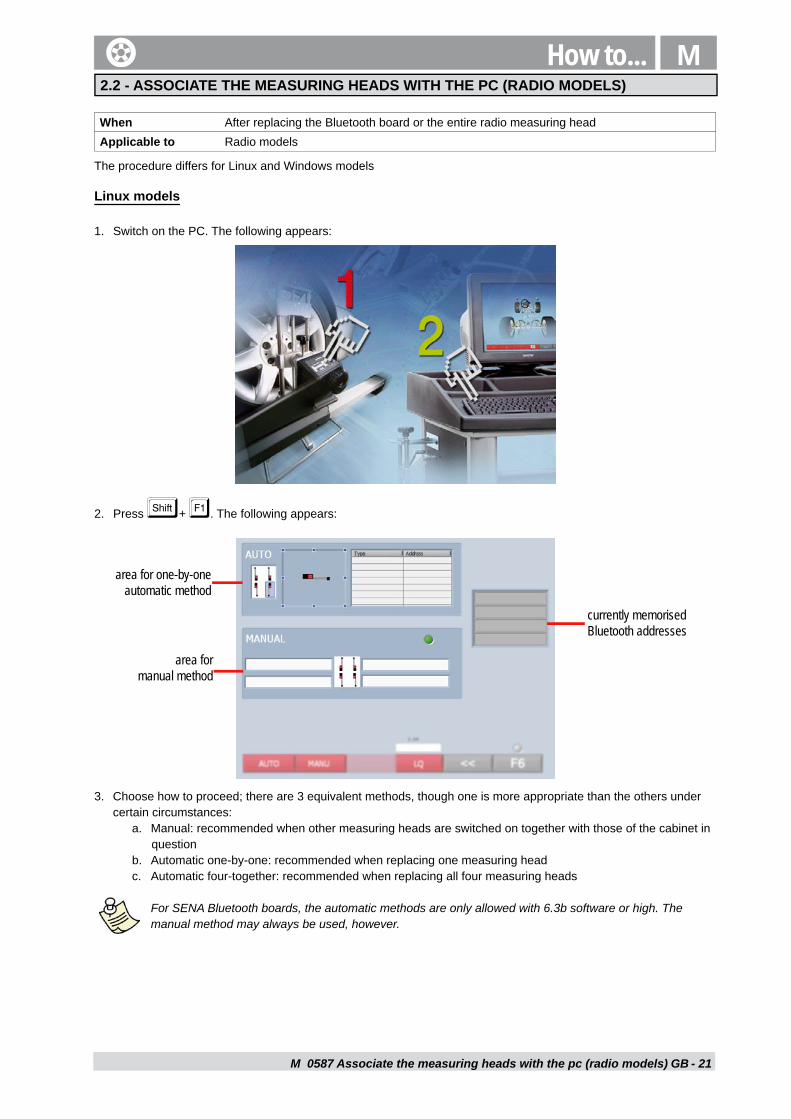
Press ¨+ �. The following appears:
Choose how to proceed; there are 3 equivalent methods, though one is more appropriate than the others under certain circumstances:
Manual: recommended when other measuring heads are switched on together with those of the cabinet in questionAutomatic one-by-one: recommended when replacing one measuring headAutomatic four-together: recommended when replacing all four measuring heads
For SENA Bluetooth boards, the automatic methods are only allowed with 6.3b software or high. The manual method may always be used, however.
1.
2.
3.
a.
b.c.
area for one-by-one automatic method
area for manual method
currently memorised Bluetooth addresses
How to...
M 0587 Associate the measuring heads with the pc (radio models) - 22
00:02:C7:AD:1D:52
GB
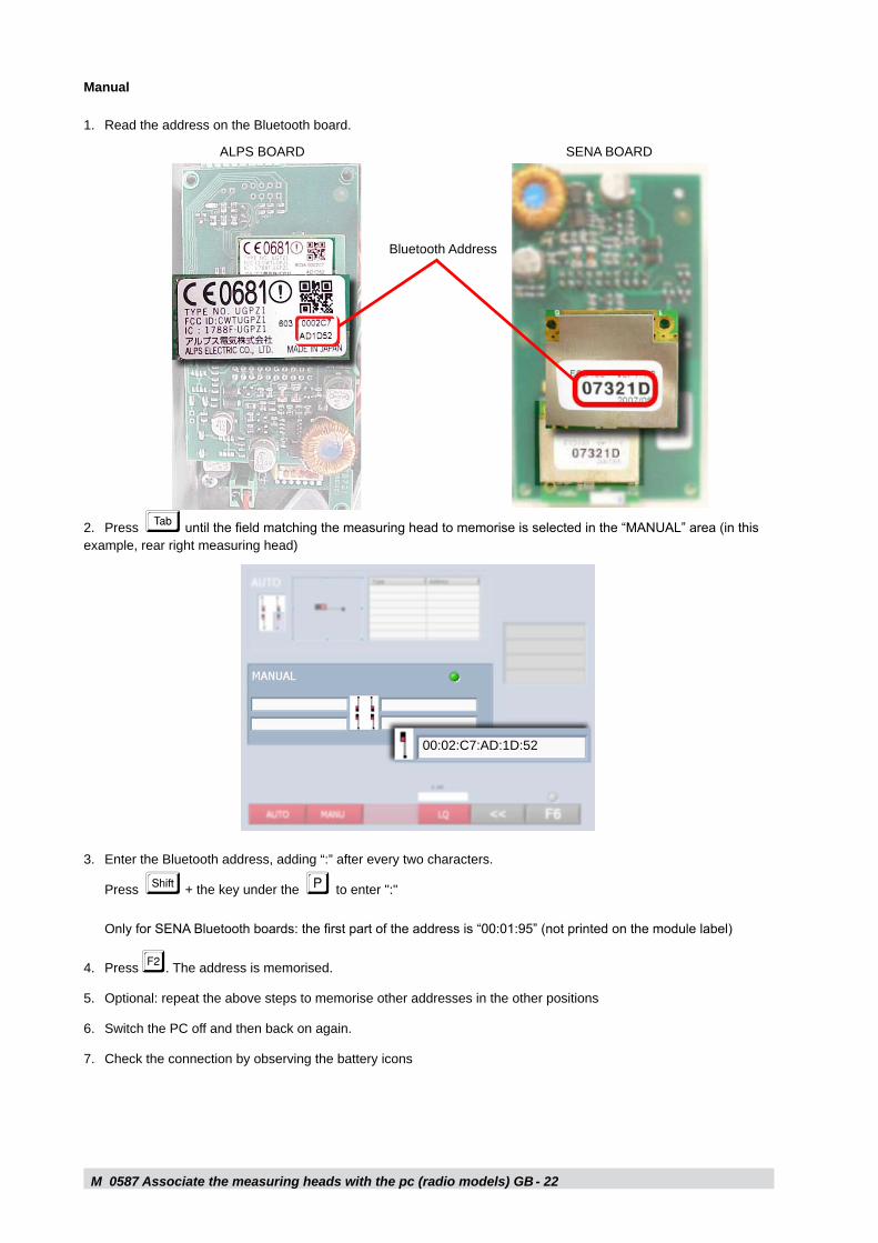
Manual
Read the address on the Bluetooth board.
Press © until the field matching the measuring head to memorise is selected in the “MANUAL” area (in this example, rear right measuring head)
Enter the Bluetooth address, adding “:” after every two characters.
Press ¨ + the key under the P to enter ":"
Only for SENA Bluetooth boards: the first part of the address is “00:01:95” (not printed on the module label)
Press �. The address is memorised.
Optional: repeat the above steps to memorise other addresses in the other positions
Switch the PC off and then back on again.
Check the connection by observing the battery icons
1.
2.
3.
4.
5.
6.
7.
Bluetooth Address
ALPS BOARD SENA BOARD
M 0587 Associate the measuring heads with the pc (radio models) - 2�
Anonymousn/a
00:02.C7:FB:A8:99
00:02.C7:FB:A9:28
GB
Automatic one-by-one
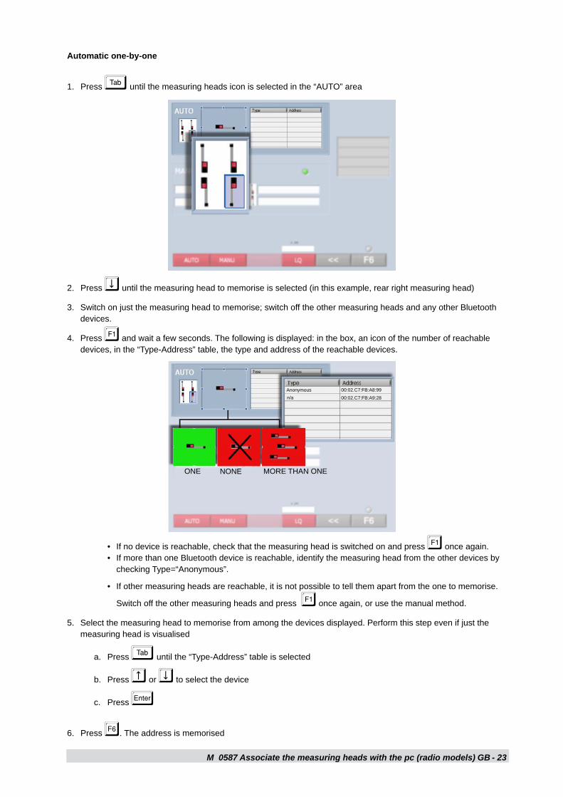
Press © until the measuring heads icon is selected in the “AUTO” area
Press ¢ until the measuring head to memorise is selected (in this example, rear right measuring head)
Switch on just the measuring head to memorise; switch off the other measuring heads and any other Bluetooth devices.
Press � and wait a few seconds. The following is displayed: in the box, an icon of the number of reachable devices, in the “Type-Address” table, the type and address of the reachable devices.
1.
2.
3.
4.
If no device is reachable, check that the measuring head is switched on and press � once again. If more than one Bluetooth device is reachable, identify the measuring head from the other devices by checking Type=“Anonymous”.
If other measuring heads are reachable, it is not possible to tell them apart from the one to memorise.
Switch off the other measuring heads and press � once again, or use the manual method.
Select the measuring head to memorise from among the devices displayed. Perform this step even if just the measuring head is visualised
Press © until the “Type-Address” table is selected
Press £ or ¢ to select the device
Press «
Press �. The address is memorised
••
•
5.
a.
b.
c.
6.
ONE NONE MORE THAN ONE
M 0587 Associate the measuring heads with the pc (radio models) - 2�
OK
GB
Optional: repeat the above steps to memorise other addresses in the other positions
Switch the PC off and then back on again.
Switch on the other measuring heads
Check the connection
Automatic four-together
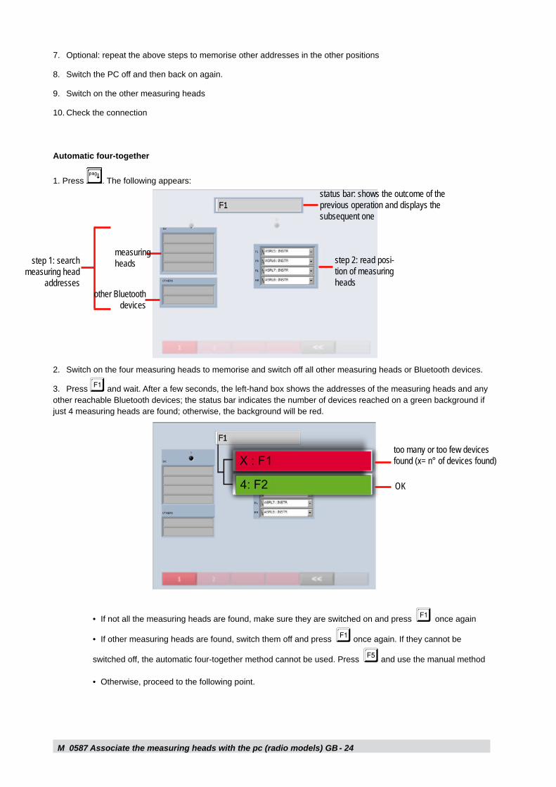
1. Press . The following appears:
7.
8.
9.
10.
Switch on the four measuring heads to memorise and switch off all other measuring heads or Bluetooth devices.
Press � and wait. After a few seconds, the left-hand box shows the addresses of the measuring heads and any other reachable Bluetooth devices; the status bar indicates the number of devices reached on a green background if just 4 measuring heads are found; otherwise, the background will be red.
If not all the measuring heads are found, make sure they are switched on and press � once again
If other measuring heads are found, switch them off and press � once again. If they cannot be
switched off, the automatic four-together method cannot be used. Press � and use the manual method
Otherwise, proceed to the following point.
2.
3.
•
•
•
step 1: search measuring head
addresses
measuring heads
other Bluetooth devices
status bar: shows the outcome of the previous operation and displays the subsequent one
step 2: read posi-tion of measuring heads
too many or too few devices found (x= n° of devices found)
M 0587 Associate the measuring heads with the pc (radio models) - 25
OK
GB
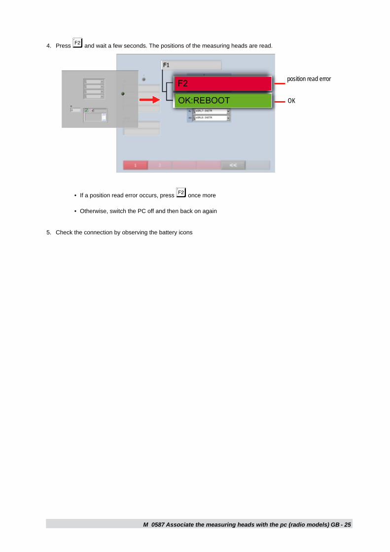
Press � and wait a few seconds. The positions of the measuring heads are read.
If a position read error occurs, press � once more
Otherwise, switch the PC off and then back on again
Check the connection by observing the battery icons
4.
•
•
5.
position read error

M 0587 Associate the measuring heads with the pc (radio models) - 2�GB
M 0587 Update measuring head firmware - 27
M
GB
How to...
When Obsolete measuring head firmwareApplicable to All measuring heads, all logic boardsInstruments required Measuring head firmware update set, code 86SB77499
PC with parallel port. The PC in the cabinet may be used
Firmware updates do not delete the parameters stored in the logic board, such as calibration and assigned position
The update programme recognises the type of logic board and automatically chooses the appropriate firmware
Assembly precAutions:
tAke cAre not to crush or bend the delicAte keyboArd connector
before disconnecting or connecting the bluetooth boArd from or to the logic boArd, disconnect the bAttery to Avoid voltAge surges.
1. Prepare the measuring head
Remove the plastic cover from the measuring head
(radio models only) For ease of access to the logic board, remove the Bluetooth board
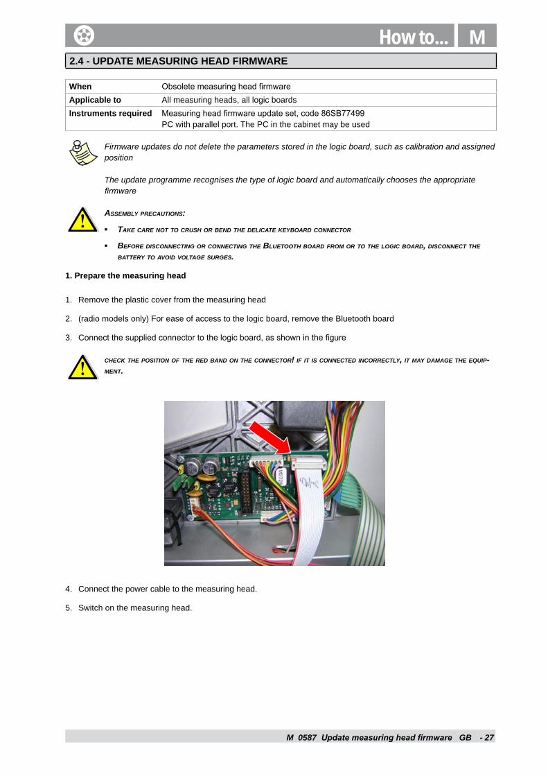
Connect the supplied connector to the logic board, as shown in the figure
check the position of the red bAnd on the connector! if it is connected incorrectly, it mAy dAmAge the equip-ment.
Connect the power cable to the measuring head.
Switch on the measuring head.
▪
▪
1.
2.
3.
4.
5.
2.4 - UPDATE MEASURING HEAD FIRMWARE
M 0587 Update measuring head firmware GB - 28
2. Prepare the PC
If using the cabinet PC, make sure the motherboard is easy to access
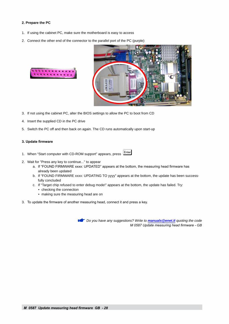
Connect the other end of the connector to the parallel port of the PC (purple)
If not using the cabinet PC, alter the BIOS settings to allow the PC to boot from CD
Insert the supplied CD in the PC drive
Switch the PC off and then back on again. The CD runs automatically upon start-up
3. Update firmware
When “Start computer with CD-ROM support” appears, press «Wait for "Press any key to continue..." to appear
If “FOUND FIRMWARE xxxx: UPDATED” appears at the bottom, the measuring head firmware has already been updatedIf “FOUND FIRMWARE xxxx: UPDATING TO yyyy” appears at the bottom, the update has been success-fully concludedIf “Target chip refused to enter debug mode!” appears at the bottom, the update has failed. Try:
checking the connectionmaking sure the measuring head are on
To update the firmware of another measuring head, connect it and press a key.
Do you have any suggestions? Write to [email protected] quoting the code M 0587 Update measuring head firmware - GB
1.
2.
3.
4.
5.
1.
2.a.
b.
c.••
3.
2.5 - HOW TO CALIBRATE MEASUREMENT HEADS
Code M D1 GB Revision 1 Language English Date September 2006 Revised by Alippi Claudio
Objective Calibrate a group of 4 measurement heads, aimed at establishing correct measurements When to perform calibration
• Group of measurement heads never previously calibrated together • Replacement of one measurement head in a previously calibrated group of heads • Incorrect measurements
Applicable on All models and all series with software M2695 r. 5.0 or later Addressed to Service technicians and dealers Prerequisites • Availability of calibration tool code 46DW69854
• System installed and functional • Basic system knowledge
M
GB
When After replacing the Bluetooth board or the entire radio measuring headApplicable to Radio models
The procedure differs for Linux and Windows models
Linux models
Switch on the PC. The following appears:
Press ¨+ �. The following appears:
Choose how to proceed; there are 3 equivalent methods, though one is more appropriate than the others under certain circumstances:
Manual: recommended when other measuring heads are switched on together with those of the cabinet in questionAutomatic one-by-one: recommended when replacing one measuring headAutomatic four-together: recommended when replacing all four measuring heads
For SENA Bluetooth boards, the automatic methods are only allowed with 6.3b software or high. The manual method may always be used, however.
1.
2.
3.
a.
b.c.
area for one-by-one automatic method
area for manual method
currently memorised Bluetooth addresses
How to...
M How to...
M 0587 How to calibrate measurement heads GB - 29
How to calibrate measurement heads
Start here To correctly calibrate the measurement heads, follow the instructions in the following chapters, in sequence starting from thefollowing chapter. Once you have gained familiarity with the procedure, you can perform it without this document by just following the instructions that appear on the screen.
This document uses the following symbols:
Indicates that care should be taken to avoid injury and equipment damage
Indicates useful information Indicates where to find the explanation of related topics
Proceed to the following chapter
Installation of the calibration tool code 46DW69854
1
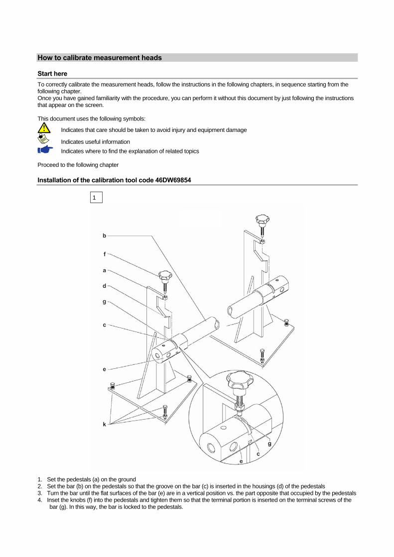
1. Set the pedestals (a) on the ground 2. Set the bar (b) on the pedestals so that the groove on the bar (c) is inserted in the housings (d) of the pedestals 3. Turn the bar until the flat surfaces of the bar (e) are in a vertical position vs. the part opposite that occupied by the pedestals 4. Inset the knobs (f) into the pedestals and tighten them so that the terminal portion is inserted on the terminal screws of the
bar (g). In this way, the bar is locked to the pedestals.
2
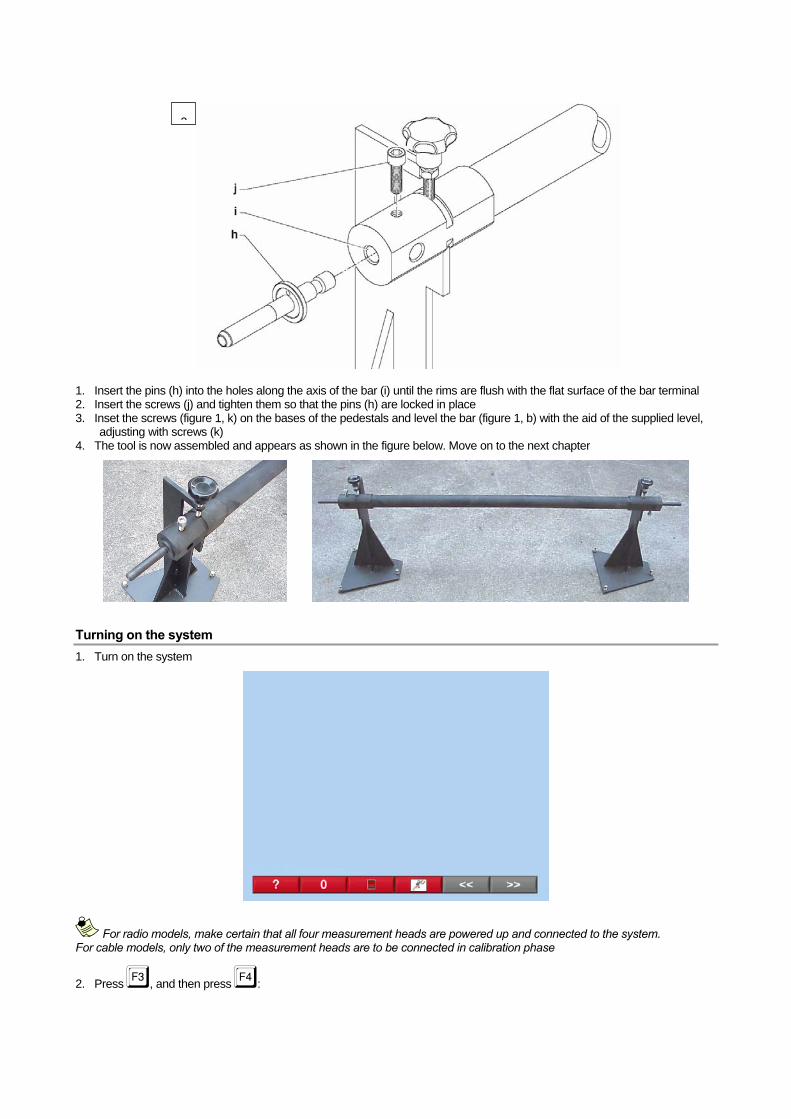
1. Insert the pins (h) into the holes along the axis of the bar (i) until the rims are flush with the flat surface of the bar terminal 2. Insert the screws (j) and tighten them so that the pins (h) are locked in place 3. Inset the screws (figure 1, k) on the bases of the pedestals and level the bar (figure 1, b) with the aid of the supplied level,
adjusting with screws (k) 4. The tool is now assembled and appears as shown in the figure below. Move on to the next chapter
Turning on the system 1. Turn on the system
For radio models, make certain that all four measurement heads are powered up and connected to the system. For cable models, only two of the measurement heads are to be connected in calibration phase
2. Press d, and then press e:
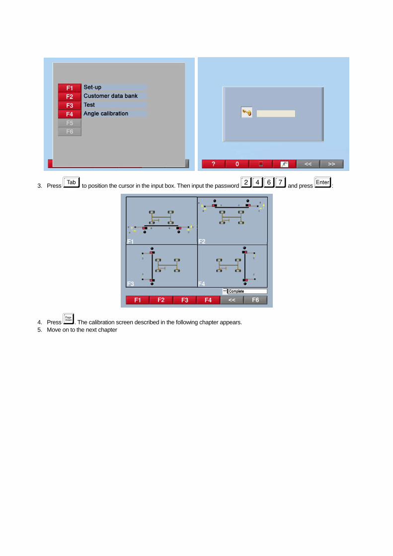
3. Press v to position the cursor in the input box. Then input the password ���� and press x:
4. Press �. The calibration screen described in the following chapter appears. 5. Move on to the next chapter
Overview of the calibration screen
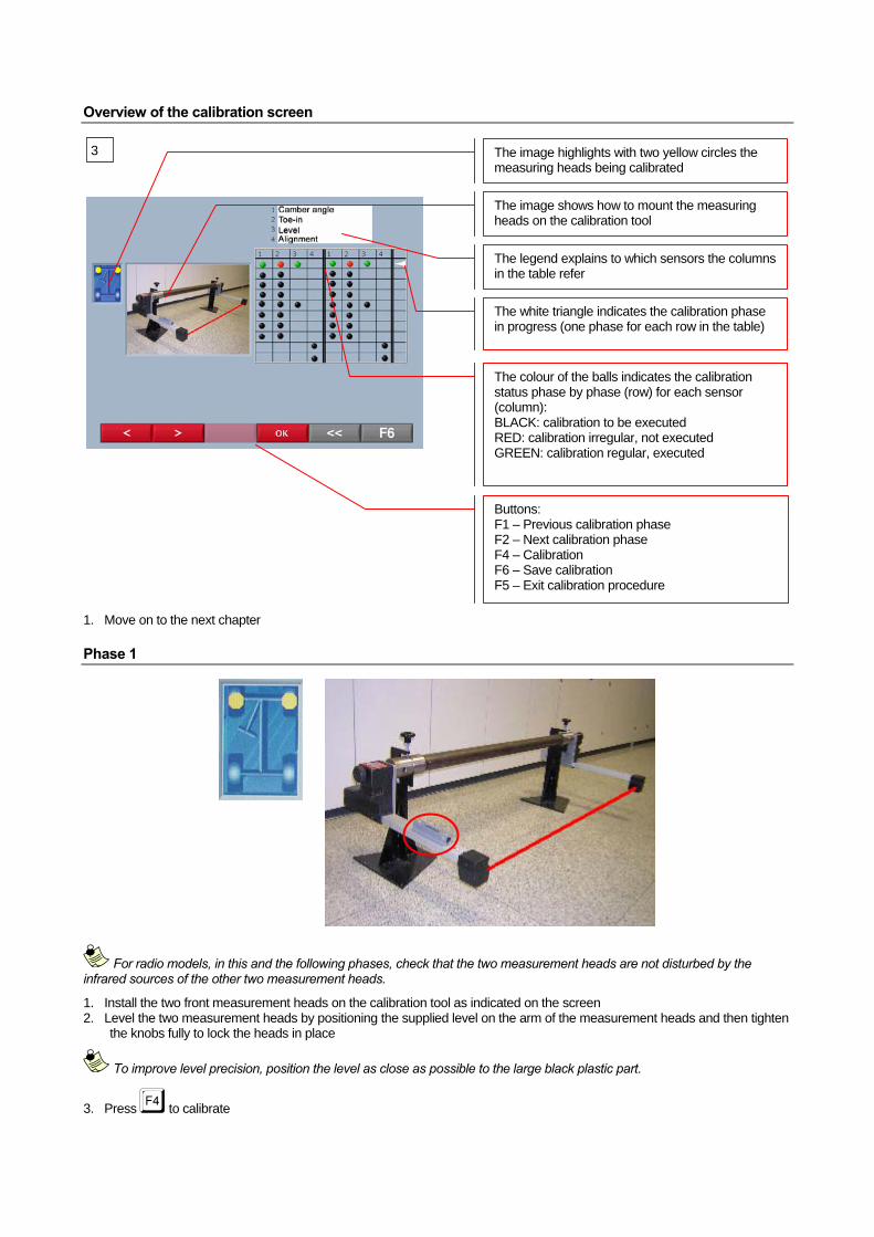
The image highlights with two yellow circles the measuring heads being calibrated
The image shows how to mount the measuring heads on the calibration tool
Buttons: F1 – Previous calibration phase F2 – Next calibration phase F4 – Calibration F6 – Save calibration F5 – Exit calibration procedure
The legend explains to which sensors the columns in the table refer
The colour of the balls indicates the calibration status phase by phase (row) for each sensor (column): BLACK: calibration to be executed RED: calibration irregular, not executed GREEN: calibration regular, executed
The white triangle indicates the calibration phase in progress (one phase for each row in the table)
3
1. Move on to the next chapter
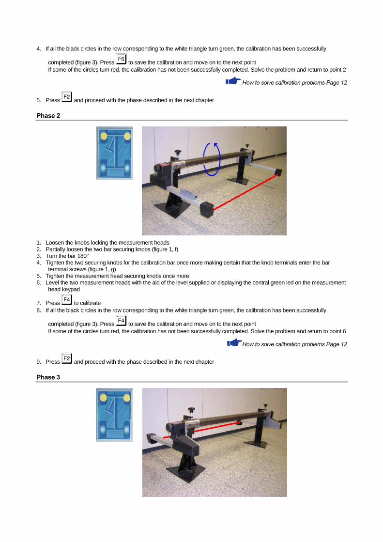
Phase 1
For radio models, in this and the following phases, check that the two measurement heads are not disturbed by the infrared sources of the other two measurement heads.
1. Install the two front measurement heads on the calibration tool as indicated on the screen 2. Level the two measurement heads by positioning the supplied level on the arm of the measurement heads and then tighten
the knobs fully to lock the heads in place
To improve level precision, position the level as close as possible to the large black plastic part.
3. Press e to calibrate
4. If all the black circles in the row corresponding to the white triangle turn green, the calibration has been successfully
completed (figure 3). Press g to save the calibration and move on to the next point If some of the circles turn red, the calibration has not been successfully completed. Solve the problem and return to point 2
How to solve calibration problems Page 12
5. Press c and proceed with the phase described in the next chapter
Phase 2
1. Loosen the knobs locking the measurement heads 2. Partially loosen the two bar securing knobs (figure 1, f) 3. Turn the bar 180° 4. Tighten the two securing knobs for the calibration bar once more making certain that the knob terminals enter the bar
terminal screws (figure 1, g) 5. Tighten the measurement head securing knobs once more 6. Level the two measurement heads with the aid of the level supplied or displaying the central green led on the measurement
head keypad
7. Press e to calibrate 8. If all the black circles in the row corresponding to the white triangle turn green, the calibration has been successfully
completed (figure 3). Press e to save the calibration and move on to the next point If some of the circles turn red, the calibration has not been successfully completed. Solve the problem and return to point 6
How to solve calibration problems Page 12
9. Press c and proceed with the phase described in the next chapter
Phase 3
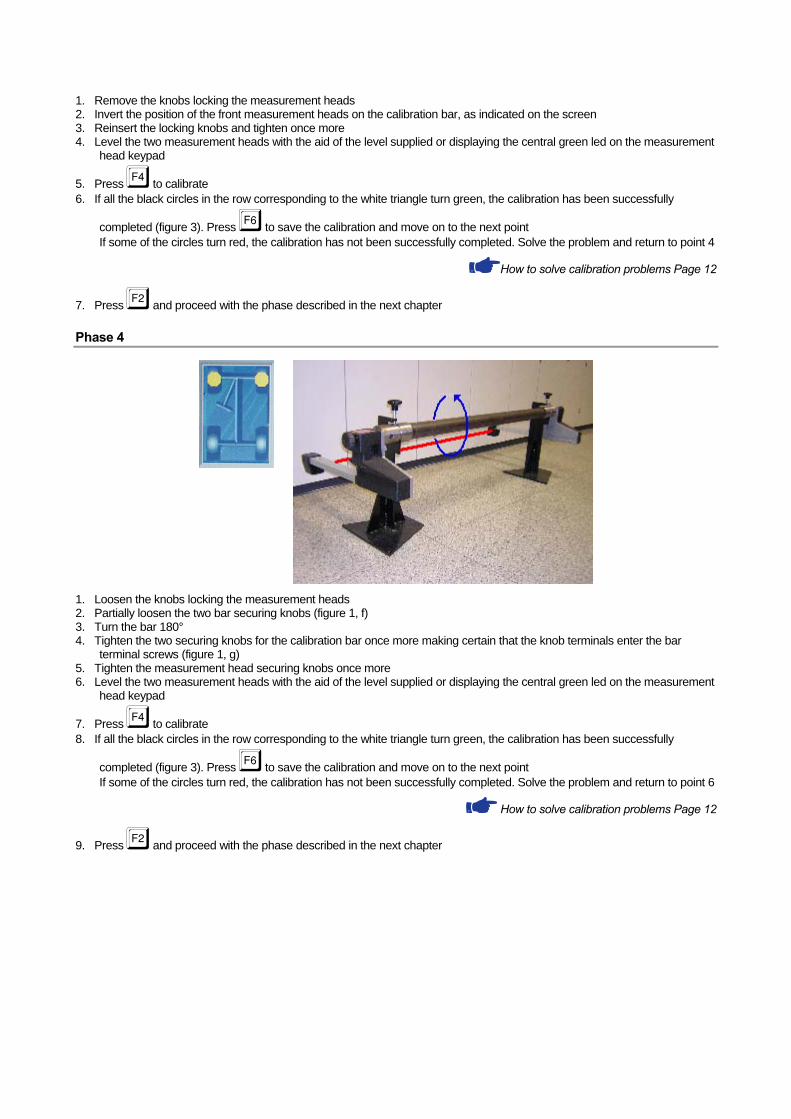
1. Remove the knobs locking the measurement heads 2. Invert the position of the front measurement heads on the calibration bar, as indicated on the screen 3. Reinsert the locking knobs and tighten once more 4. Level the two measurement heads with the aid of the level supplied or displaying the central green led on the measurement
head keypad
5. Press e to calibrate 6. If all the black circles in the row corresponding to the white triangle turn green, the calibration has been successfully
completed (figure 3). Press g to save the calibration and move on to the next point If some of the circles turn red, the calibration has not been successfully completed. Solve the problem and return to point 4
How to solve calibration problems Page 12
7. Press c and proceed with the phase described in the next chapter
Phase 4
1. Loosen the knobs locking the measurement heads 2. Partially loosen the two bar securing knobs (figure 1, f) 3. Turn the bar 180° 4. Tighten the two securing knobs for the calibration bar once more making certain that the knob terminals enter the bar
terminal screws (figure 1, g) 5. Tighten the measurement head securing knobs once more 6. Level the two measurement heads with the aid of the level supplied or displaying the central green led on the measurement
head keypad
7. Press e to calibrate 8. If all the black circles in the row corresponding to the white triangle turn green, the calibration has been successfully
completed (figure 3). Press g to save the calibration and move on to the next point If some of the circles turn red, the calibration has not been successfully completed. Solve the problem and return to point 6
How to solve calibration problems Page 12
9. Press c and proceed with the phase described in the next chapter
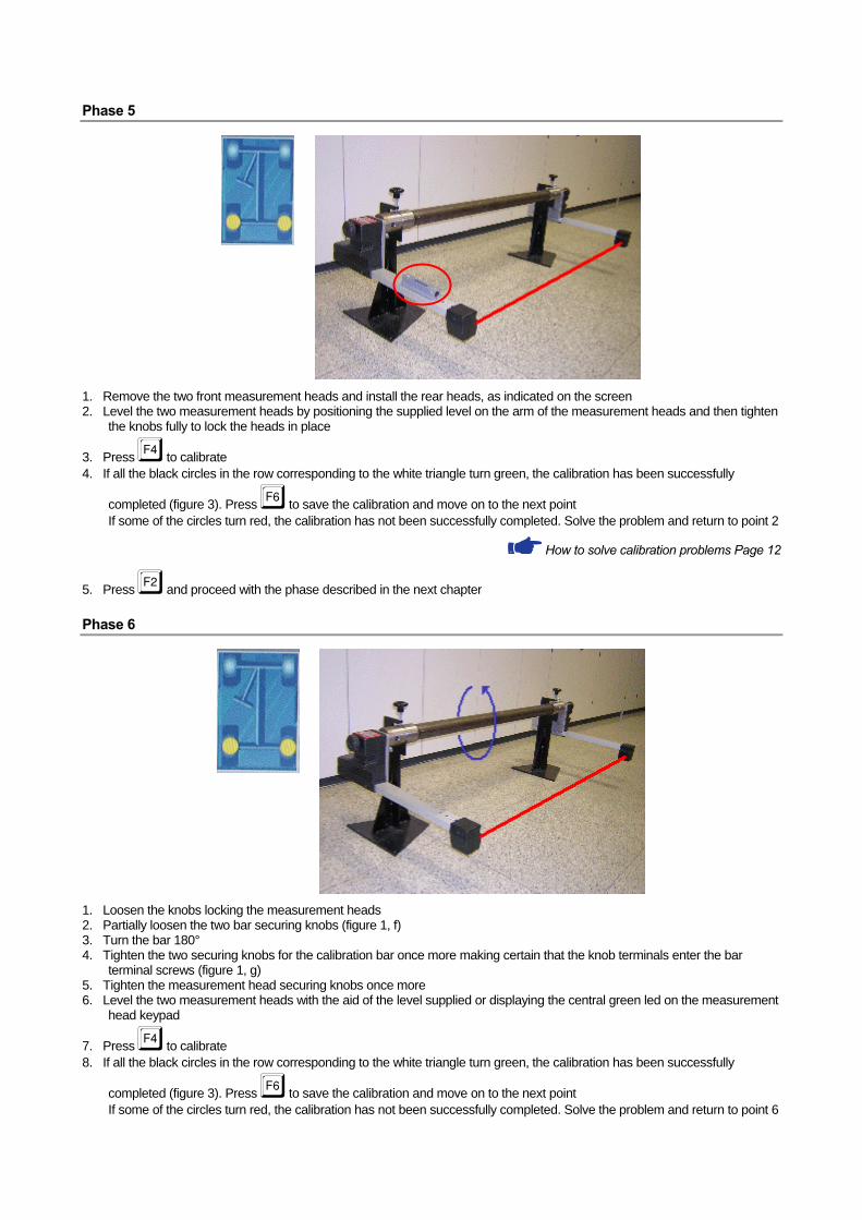
Phase 5
1. Remove the two front measurement heads and install the rear heads, as indicated on the screen 2. Level the two measurement heads by positioning the supplied level on the arm of the measurement heads and then tighten
the knobs fully to lock the heads in place
3. Press e to calibrate 4. If all the black circles in the row corresponding to the white triangle turn green, the calibration has been successfully
completed (figure 3). Press g to save the calibration and move on to the next point If some of the circles turn red, the calibration has not been successfully completed. Solve the problem and return to point 2
How to solve calibration problems Page 12
5. Press c and proceed with the phase described in the next chapter
Phase 6
1. Loosen the knobs locking the measurement heads 2. Partially loosen the two bar securing knobs (figure 1, f) 3. Turn the bar 180° 4. Tighten the two securing knobs for the calibration bar once more making certain that the knob terminals enter the bar
terminal screws (figure 1, g) 5. Tighten the measurement head securing knobs once more 6. Level the two measurement heads with the aid of the level supplied or displaying the central green led on the measurement
head keypad
7. Press e to calibrate 8. If all the black circles in the row corresponding to the white triangle turn green, the calibration has been successfully
completed (figure 3). Press g to save the calibration and move on to the next point If some of the circles turn red, the calibration has not been successfully completed. Solve the problem and return to point 6
How to solve calibration problems Page 12
9. Press c and proceed with the phase described in the next chapter
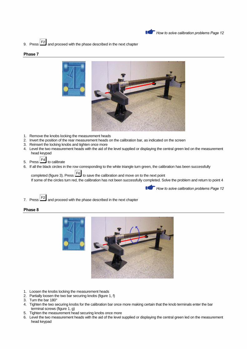
Phase 7
1. Remove the knobs locking the measurement heads 2. Invert the position of the rear measurement heads on the calibration bar, as indicated on the screen 3. Reinsert the locking knobs and tighten once more 4. Level the two measurement heads with the aid of the level supplied or displaying the central green led on the measurement
head keypad
5. Press e to calibrate 6. If all the black circles in the row corresponding to the white triangle turn green, the calibration has been successfully
completed (figure 3). Press g to save the calibration and move on to the next point If some of the circles turn red, the calibration has not been successfully completed. Solve the problem and return to point 4
How to solve calibration problems Page 12
7. Press c and proceed with the phase described in the next chapter
Phase 8
1. Loosen the knobs locking the measurement heads 2. Partially loosen the two bar securing knobs (figure 1, f) 3. Turn the bar 180° 4. Tighten the two securing knobs for the calibration bar once more making certain that the knob terminals enter the bar
terminal screws (figure 1, g) 5. Tighten the measurement head securing knobs once more 6. Level the two measurement heads with the aid of the level supplied or displaying the central green led on the measurement
head keypad
7. Press e to calibrate 8. If all the black circles in the row corresponding to the white triangle turn green, the calibration has been successfully
completed (figure 3). Press g to save the calibration and move on to the next point If some of the circles turn red, the calibration has not been successfully completed. Solve the problem and return to point 6
How to solve calibration problems Page 12
9. Press c and proceed with the phase described in the next chapter
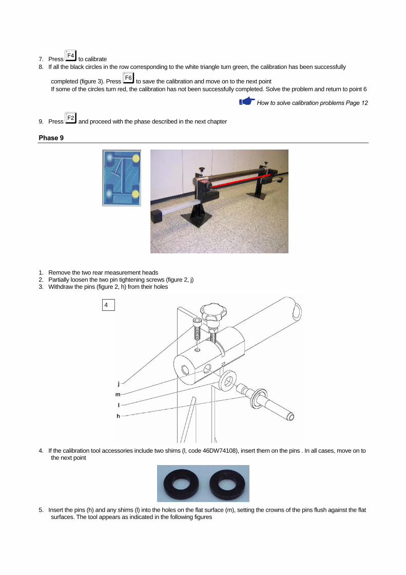
Phase 9
1. Remove the two rear measurement heads 2. Partially loosen the two pin tightening screws (figure 2, j) 3. Withdraw the pins (figure 2, h) from their holes
4
4. If the calibration tool accessories include two shims (l, code 46DW74108), insert them on the pins . In all cases, move on to the next point
5. Insert the pins (h) and any shims (l) into the holes on the flat surface (m), setting the crowns of the pins flush against the flat surfaces. The tool appears as indicated in the following figures
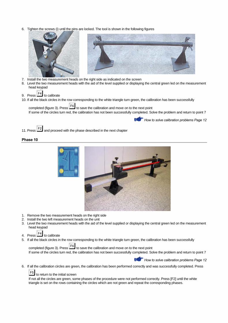
6. Tighten the screws (i) until the pins are locked. The tool is shown in the following figures
7. Install the two measurement heads on the right side as indicated on the screen 8. Level the two measurement heads with the aid of the level supplied or displaying the central green led on the measurement
head keypad
9. Press e to calibrate 10. If all the black circles in the row corresponding to the white triangle turn green, the calibration has been successfully
completed (figure 3). Press g to save the calibration and move on to the next point If some of the circles turn red, the calibration has not been successfully completed. Solve the problem and return to point 7
How to solve calibration problems Page 12
11. Press c and proceed with the phase described in the next chapter
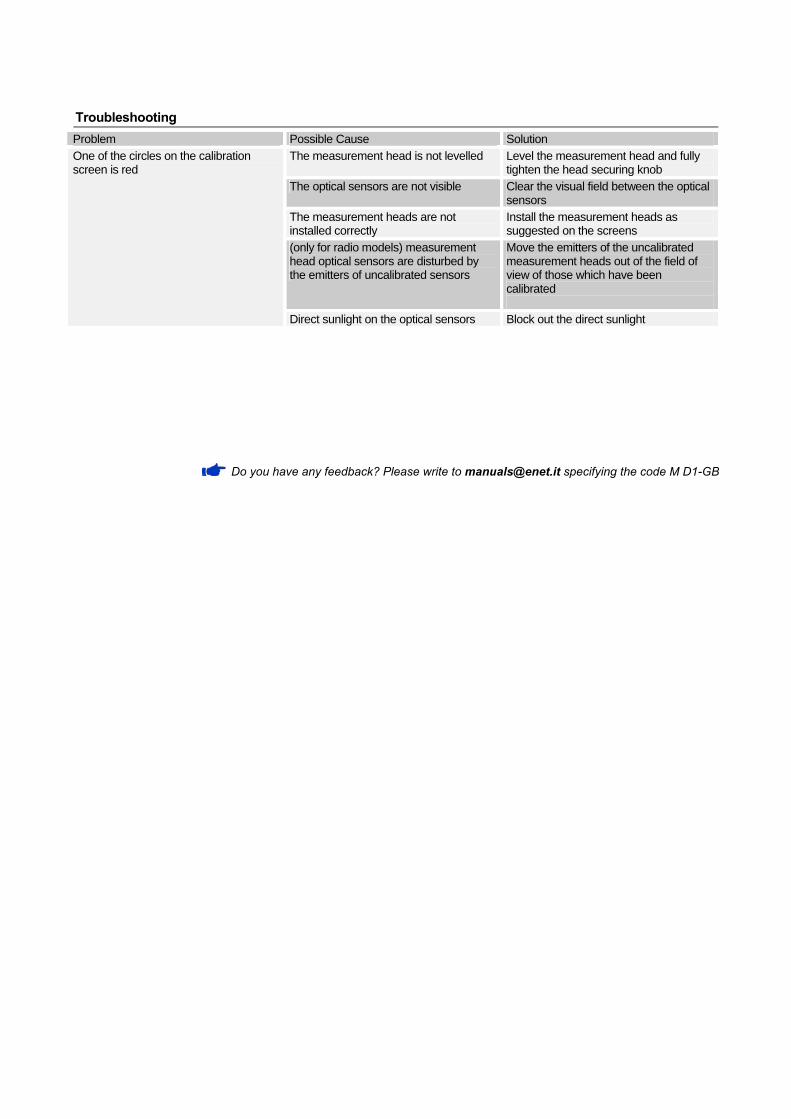
Phase 10
1. Remove the two measurement heads on the right side 2. Install the two left measurement heads on the unit 3. Level the two measurement heads with the aid of the level supplied or displaying the central green led on the measurement
head keypad
4. Press e to calibrate 5. If all the black circles in the row corresponding to the white triangle turn green, the calibration has been successfully
completed (figure 3). Press g to save the calibration and move on to the next point If some of the circles turn red, the calibration has not been successfully completed. Solve the problem and return to point 7
How to solve calibration problems Page 12
6. If all the calibration circles are green, the calibration has been performed correctly and was successfully completed. Press
f to return to the initial screen If not all the circles are green, some phases of the procedure were not performed correctly. Press [F2] until the white triangle is set on the rows containing the circles which are not green and repeat the corresponding phases.
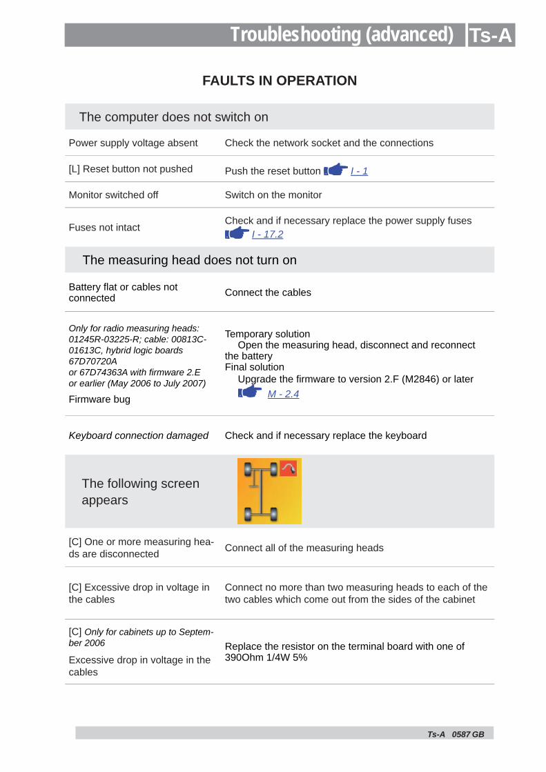
Troubleshooting Problem Possible Cause Solution One of the circles on the calibration The measurement head is not levelled Level the measurement head and fully screen is red tighten the head securing knob
The optical sensors are not visible Clear the visual field between the optical sensors
The measurement heads are not Install the measurement heads as installed correctly suggested on the screens (only for radio models) measurement head optical sensors are disturbed by the emitters of uncalibrated sensors
Move the emitters of the uncalibrated measurement heads out of the field of view of those which have been calibrated
Direct sunlight on the optical sensors Block out the direct sunlight
Do you have any feedback? Please write to [email protected] specifying the code M D1-GB
Ts-A 0587
Ts-A
GB
FAULTS IN OPERATION
The computer does not switch on
Power supply voltage absent Check the network socket and the connections
[L] Reset button not pushed Push the reset button I - 1
Monitor switched off Switch on the monitor
Fuses not intactCheck and if necessary replace the power supply fuses
I - 17.2
The measuring head does not turn on
Battery fl at or cables not connected Connect the cables
Only for radio measuring heads: 01245R-03225-R; cable: 00813C-01613C, hybrid logic boards 67D70720A or 67D74363A with fi rmware 2.E or earlier (May 2006 to July 2007)
Firmware bug
Temporary solutionOpen the measuring head, disconnect and reconnect
the batteryFinal solution
Upgrade the fi rmware to version 2.F (M2846) or later M - 2.4
Keyboard connection damaged Check and if necessary replace the keyboard
The following screen appears
[C] One or more measuring hea-ds are disconnected Connect all of the measuring heads
[C] Excessive drop in voltage in the cables
Connect no more than two measuring heads to each of the two cables which come out from the sides of the cabinet
[C] Only for cabinets up to Septem-ber 2006
Excessive drop in voltage in the cables
Replace the resistor on the terminal board with one of 390Ohm 1/4W 5%
Troubleshooting (advanced)
Ts-A 0587 GB
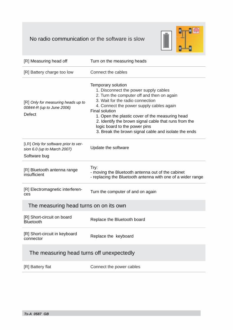
No radio communication or the software is slow
[R] Measuring head off Turn on the measuring heads
[R] Battery charge too low Connect the cables
[R] Only for measuring heads up to 00844-R (up to June 2006)
Defect
Temporary solution1. Disconnect the power supply cables2. Turn the computer off and then on again3. Wait for the radio connection4. Connect the power supply cables again
Final solution1. Open the plastic cover of the measuring head2. Identify the brown signal cable that runs from the logic board to the power pins3. Break the brown signal cable and isolate the ends
[LR] Only for software prior to ver-sion 6.0 (up to March 2007)
Software bug
Update the software
[R] Bluetooth antenna range insuffi cient
Try:- moving the Bluetooth antenna out of the cabinet- replacing the Bluetooth antenna with one of a wider range
[R] Electromagnetic interferen-ces Turn the computer of and on again
The measuring head turns on on its own
[R] Short-circuit on board Bluetooth Replace the Bluetooth board
[R] Short-circuit in keyboard connector Replace the keyboard
The measuring head turns off unexpectedly
[R] Battery fl at Connect the power cables
Ts-A 0587 GB
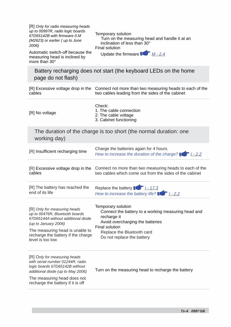
[R] Only for radio measuring heads up to 00997R, radio logic boards 67D65142B with fi rmware 0.M (M2623) or earlier ( up to June 2006)
Automatic switch-off because the measuring head is inclined by more than 30°
Temporary solutionTurn on the measuring head and handle it at an inclination of less than 30°
Final solutionUpdate the fi rmware M - 2.4
Battery recharging does not start (the keyboard LEDs on the home page do not fl ash)
[R] Excessive voltage drop in the cables
Connect not more than two measuring heads to each of the two cables leading from the sides of the cabinet
[R] No voltageCheck:1. The cable connection2. The cable voltage3. Cabinet functioning
The duration of the charge is too short (the normal duration: one working day)
[R] Insuffi cient recharging time Charge the batteries again for 4 hours.How to increase the duration of the charge? I - 2.2
[R] Excessive voltage drop in the cables
Connect no more than two measuring heads to each of the two cables which come out from the sides of the cabinet
[R] The battery has reached the end of its life
Replace the battery I - 17.3How to increase the battery life? I - 2.2
[R] Only for measuring heads up to 00476R, Bluetooth boards 67D65144A without additional diode (up to January 2006)
The measuring head is unable to recharge the battery if the charge level is too low
Temporary solutionConnect the battery to a working measuring head and recharge itAvoid overcharging the batteries
Final solutionReplace the Bluetooth cardDo not replace the battery
[R] Only for measuring heads with serial number 01244R, radio logic boards 67D65142B without additional diode (up to May 2006)
The measuring head does not recharge the battery if it is off
Turn on the measuring head to recharge the battery
Ts-A 0587 GB
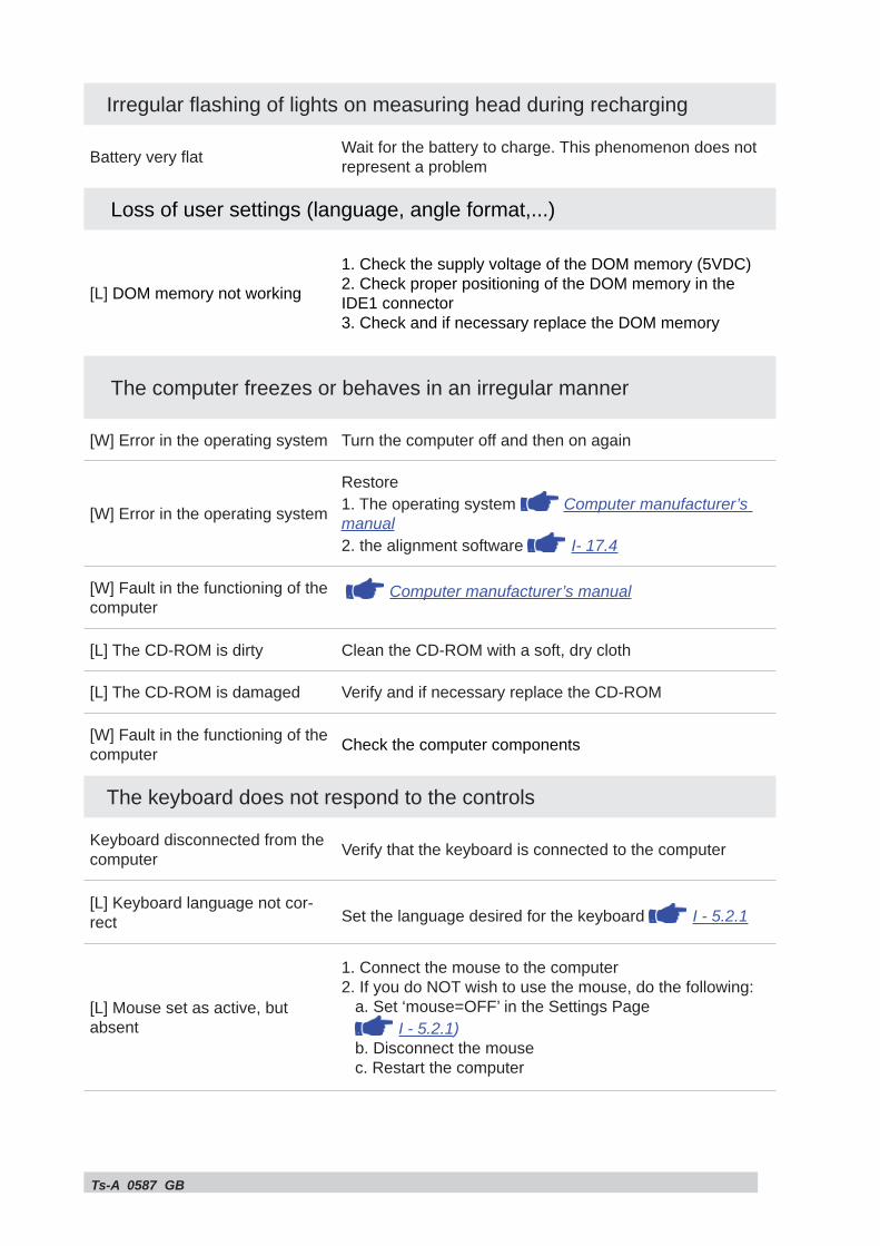
Irregular fl ashing of lights on measuring head during recharging
Battery very fl at Wait for the battery to charge. This phenomenon does not represent a problem
Loss of user settings (language, angle format,...)
[L] DOM memory not working
1. Check the supply voltage of the DOM memory (5VDC)2. Check proper positioning of the DOM memory in the IDE1 connector3. Check and if necessary replace the DOM memory
The computer freezes or behaves in an irregular manner
[W] Error in the operating system Turn the computer off and then on again
[W] Error in the operating system
Restore1. The operating system Computer manufacturer’s manual2. the alignment software I- 17.4
[W] Fault in the functioning of the computer
Computer manufacturer’s manual
[L] The CD-ROM is dirty Clean the CD-ROM with a soft, dry cloth
[L] The CD-ROM is damaged Verify and if necessary replace the CD-ROM
[W] Fault in the functioning of the computer Check the computer components
The keyboard does not respond to the controls
Keyboard disconnected from the computer Verify that the keyboard is connected to the computer
[L] Keyboard language not cor-rect Set the language desired for the keyboard I - 5.2.1
[L] Mouse set as active, but absent
1. Connect the mouse to the computer2. If you do NOT wish to use the mouse, do the following: a. Set ‘mouse=OFF’ in the Settings Page I - 5.2.1) b. Disconnect the mouse c. Restart the computer
Ts-A 0587 GB
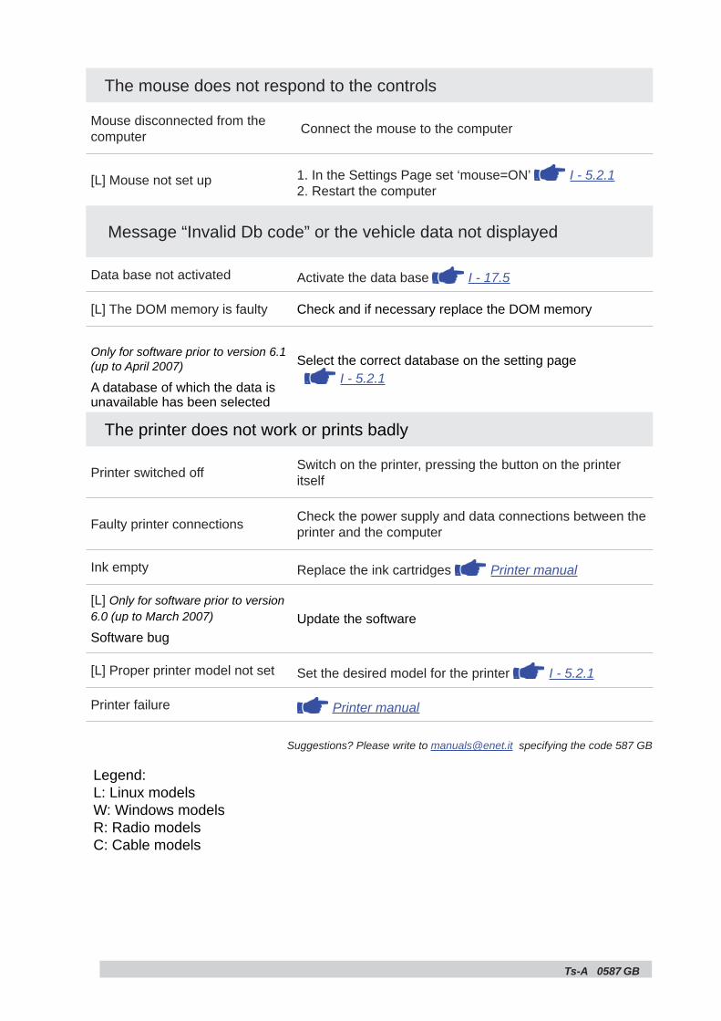
The mouse does not respond to the controls
Mouse disconnected from the computer Connect the mouse to the computer
[L] Mouse not set up 1. In the Settings Page set ‘mouse=ON’ I - 5.2.12. Restart the computer
Message “Invalid Db code” or the vehicle data not displayed
Data base not activated Activate the data base I - 17.5
[L] The DOM memory is faulty Check and if necessary replace the DOM memory
Only for software prior to version 6.1 (up to April 2007)
A database of which the data is unavailable has been selected
Select the correct database on the setting page I - 5.2.1
The printer does not work or prints badly
Printer switched off Switch on the printer, pressing the button on the printer itself
Faulty printer connections Check the power supply and data connections between the printer and the computer
Ink empty Replace the ink cartridges Printer manual
[L] Only for software prior to version 6.0 (up to March 2007)
Software bugUpdate the software
[L] Proper printer model not set Set the desired model for the printer I - 5.2.1
Printer failure Printer manual
Suggestions? Please write to [email protected] specifying the code 587 GB
Legend:L: Linux modelsW: Windows modelsR: Radio modelsC: Cable models
Ts-A 0587 GB
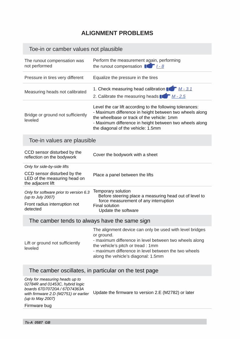
ALIGNMENT PROBLEMS
Toe-in or camber values not plausible
The runout compensation was not performed
Perform the measurement again, performing the runout compensation I - 8
Pressure in tires very different Equalize the pressure in the tires
Measuring heads not calibrated 1. Check measuring head calibration M - 3.12. Calibrate the measuring heads M - 2.5
Bridge or ground not suffi ciently leveled
Level the car lift according to the following tolerances:- Maximum difference in height between two wheels along the wheelbase or track of the vehicle: 1mm- Maximum difference in height between two wheels along the diagonal of the vehicle: 1.5mm
Toe-in values are plausible
CCD sensor disturbed by the refl ection on the bodywork Cover the bodywork with a sheet
Only for side-by-side lifts
CCD sensor disturbed by the LED of the measuring head on the adjacent lift
Place a panel between the lifts
Only for software prior to version 6.3 (up to July 2007)
Front radius interruption not detected
Temporary solutionBefore steering place a measuring head out of level to force measurement of any interruption
Final solutionUpdate the software
The camber tends to always have the same sign
Lift or ground not suffi ciently leveled
The alignment device can only be used with level bridges or ground.- maximum difference in level between two wheels along the vehicle’s pitch or tread : 1mm- maximum difference in level between the two wheels along the vehicle’s diagonal: 1.5mm
The camber oscillates, in particular on the test page Only for measuring heads up to 02784R and 01453C, hybrid logic boards 67D70720A / 67D74363A with fi rmware 2.D (M2751) or earlier (up to May 2007)
Firmware bug
Update the fi rmware to version 2.E (M2782) or later
Ts-A 0587 GB
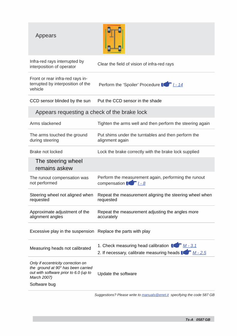
Appears
Infra-red rays interrupted by interposition of operator Clear the fi eld of vision of infra-red rays
Front or rear infra-red rays in-terrupted by interposition of the vehicle
Perform the ‘Spoiler’ Procedure I - 14
CCD sensor blinded by the sun Put the CCD sensor in the shade
Appears requesting a check of the brake lock
Arms slackened Tighten the arms well and then perform the steering again
The arms touched the ground during steering
Put shims under the turntables and then perform the alignment again
Brake not locked Lock the brake correctly with the brake lock supplied
The steering wheelremains askew
The runout compensation was not performed
Perform the measurement again, performing the runout compensation I - 8
Steering wheel not aligned when requested
Repeat the measurement aligning the steering wheel when requested
Approximate adjustment of the alignment angles
Repeat the measurement adjusting the angles more accurately
Excessive play in the suspension Replace the parts with play
Measuring heads not calibrated 1. Check measuring head calibration M - 3.12. If necessary, calibrate measuring heads M - 2.5
Only if eccentricity correction on the ground at 90° has been carried out with software prior to 6.0 (up to March 2007)
Software bug
Update the software
Suggestions? Please write to [email protected] specifying the code 587 GB

Ts-A 0587 GB
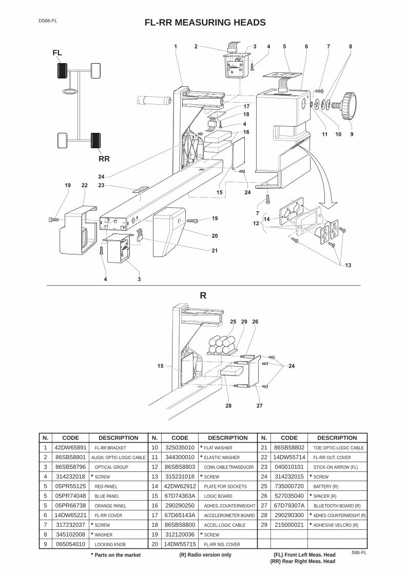
586-FL
N. CODE DESCRIPTION N. CODE DESCRIPTION N. CODE DESCRIPTION1 42DW65891 FL-RR BRACKET
2 86SB58801 ALIGN. OPTIC-LOGIC CABLE
3 86SB58796 OPTICAL GROUP
4 314232018 * SCREW
5 05PR55125 RED PANEL
5 05PR74048 BLUE PANEL
5 05PR66738 ORANGE PANEL
6 14DW65221 FL-RR COVER
7 317232037 * SCREW
8 345102008 * WASHER
9 065054010 LOCKING KNOB
10 325035010 * FLAT WASHER
11 344300010 * ELASTIC WASHER
12 86SB58803 CONN.CABLE TRANSDUCER
13 315231018 * SCREW
14 42DW62912 PLATE FOR SOCKETS
15 67D74363A LOGIC BOARD
16 290290250 ADHES. COUNTERWEIGHT
17 67D65143A ACCELEROMETER BOARD
18 86SB58800 ACCEL-LOGIC CABLE
19 312120036 * SCREW
20 14DW55715 FL-RR INS. COVER
21 86SB58802 TOE OPTIC-LOGIC CABLE
22 14DW55714 FL-RR OUT. COVER
23 040010101 STICK-ON ARROW (FL)
24 314232015 * SCREW
25 735000720 BATTERY (R)
26 527035040 * SPACER (R)
27 67D79307A BLUETOOTH BOARD (R)
28 290290300 * ADHES. COUNTERWEIGHT (R)
29 215000021 * ADHESIVE VELCRO (R)
FL-RR MEASURING HEADS
R
D586-FL
* Parts on the market (R) Radio version only (FL) Front Left Meas. Head(RR) Rear Right Meas. Head
FL
RR
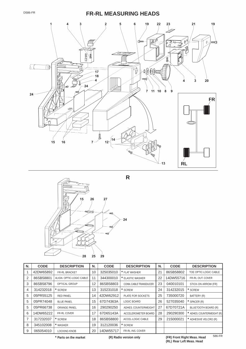
586-FR
N. CODE DESCRIPTION N. CODE DESCRIPTION N. CODE DESCRIPTION1 42DW65892 FR-RL BRACKET
2 86SB58801
3 86SB58796
4 314232018 * SCREW
5 05PR55125 RED PANEL
5 05PR74048 BLUE PANEL
5 05PR66738 ORANGE PANEL
6 14DW65222
7 317232037 * SCREW
8 345102008 * WASHER
9 065054010 LOCKING KNOB
10 325035010 * FLAT WASHER
11 344300010 * ELASTIC WASHER
12 86SB58803 CONN.CABLE TRANSDUCER
13 315231018 * SCREW
14 42DW62912 PLATE FOR SOCKETS
15 67D74363A
16 290290250 ADHES. COUNTERWEIGHT
17 67D65143A ACCELEROMETER BOARD
18 86SB58800
19 312120036 * SCREW
20 14DW55717
21 86SB58802
22 14DW55716
23 040010101 STICK-ON ARROW (FR)
24 314232015 * SCREW
25 735000720 BATTERY (R)
26 527035040 * SPACER (R)
27 67D70721A BLUETOOTH BOARD (R)
28 290290300 * ADHES. COUNTERWEIGHT (R)
29 215000021 * ADHESIVE VELCRO (R)
FR-RL MEASURING HEADSD586-FR
R
* Parts on the market (R) Radio version only (FR) Front Right Meas. Head(RL) Rear Left Meas. Head
ALIGN. OPTIC-LOGIC CABLE
OPTICAL GROUP
FR-RL COVER
LOGIC BOARD
ACCEL-LOGIC CABLE
FR-RL INS. COVER
FR-RL OUT. COVER
TOE OPTIC-LOGIC CABLE
FR
RL
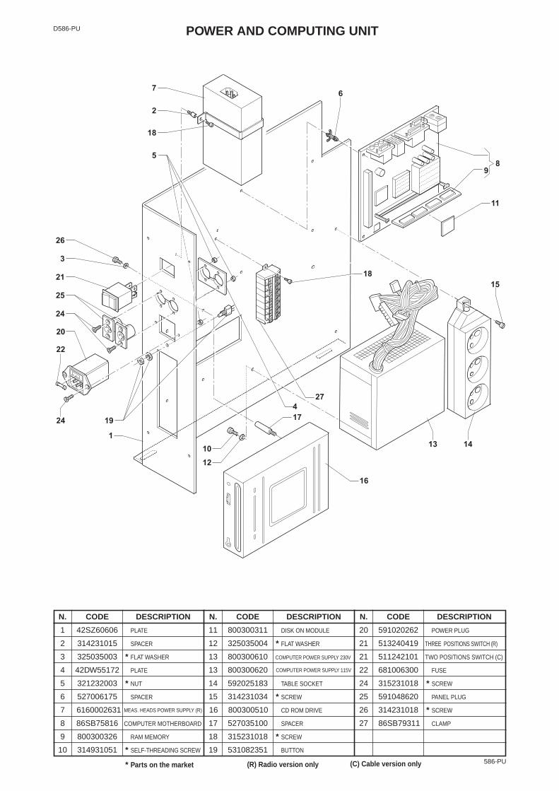
POWER AND COMPUTING UNITD586-PU
586-PU
N. CODE DESCRIPTION N. CODE DESCRIPTION N. CODE DESCRIPTION1 42SZ60606 PLATE
2 314231015 SPACER
3 325035003 * FLAT WASHER
4 42DW55172 PLATE
5 321232003 * NUT
6 527006175 SPACER
7 6160002631 MEAS. HEADS POWER SUPPLY (R)
8 86SB75816 COMPUTER MOTHERBOARD
9 800300326 RAM MEMORY
10 314931051 * SELF-THREADING SCREW
11 800300311 DISK ON MODULE
12 325035004 * FLAT WASHER
13 800300610 COMPUTER POWER SUPPLY 230V
13 800300620
14 592025183 TABLE SOCKET
15 314231034 * SCREW
16 800300510 CD ROM DRIVE
17 527035100 SPACER
18 315231018 * SCREW
19 531082351 BUTTON
20 591020262 POWER PLUG
21 513240419 THREE POSITIONS SWITCH (R)
21 511242101 TWO POSITIONS SWITCH (C)
22 681006300 FUSE
24 315231018 * SCREW
25 591048620 PANEL PLUG
26 314231018 * SCREW
27 86SB79311 CLAMP
* Parts on the market (R) Radio version only
COMPUTER POWER SUPPLY 115V
(C) Cable version only
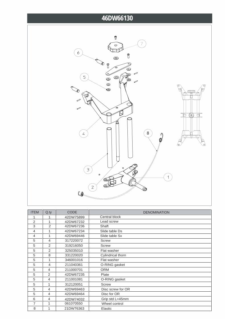
46DW66130
7 1 061070550 Wheel control
5 4 211000701 ORM
5 4 211001081 O-RING gasket
5 4 211040361 O-RING gasket
5 1 312120051 Screw
5 4 317220072 Screw5 2 319216050 Screw5 2 325035010 Flat washer 5 8 331220020 Cylindrical thorn5 1 346001016 Flat washer
2 1 42DW67232 Lead screw
4 1 42DW67234 Slide table Ds
5 2 42DW67235 Plate
3 2 42DW67236 Shaft
4 1 42DW69446 Slide table Sx
5 4 42DW69463 Disc screw for OR 5 4 42DW69464 Disc for OR6 4 42DW74032 Grip std L=45mm
1 1 42DW75899 Central blockITEM Q.ty CODE DENOMINATION
8 1 21DW76363 Elastic
8
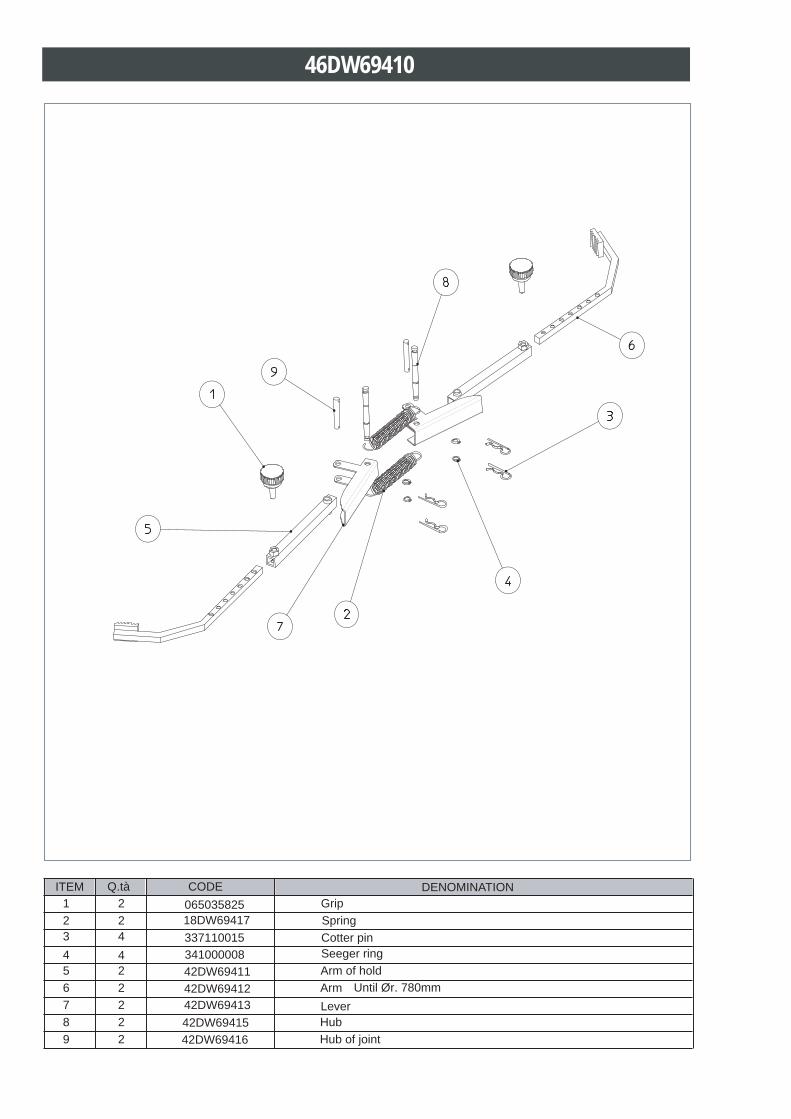
46DW69410
1 2 065035825 Grip2 2 18DW69417 Spring3 4 337110015 Cotter pin4 4 341000008 Seeger ring5 2 42DW69411 Arm of hold6 2 42DW69412 Arm7 2 42DW69413 Lever8 2 42DW69415 Hub 9 2 42DW69416 Hub of joint
Until Ør. 780mm
ITEM Q.tà CODE DENOMINATION