Embed Size (px)
Citation preview
Send Orders for Reprints to [email protected]
266 The Open Mechanical Engineering Journal, 2015, 9, 266-270
1874-155X/15 2015 Bentham Open
Open Access
Strength Analysis and Experiment of High Speed Railway Gearbox Bracket Jianwei Yang*,1,2, Minghan Yang1,2, Xi Li3 and Xing Wang4
1School of Machine-Electricity and Automobile Engineering, Beijing University of Civil Engineering Architecture, Beijing, 100044, China 2Beijing Engineering Research Center of Monitoring for Construction Safety, Beijing University of Civil Engineering Architecture, Beijing, 100044, China 3Subway Operation Technology Centre, Mass Transit Railway Operation Corporation LTD, Beijing, 102208, China 4School of Computing, Taiyuan University of Science and Technology, Taiyuan, Shanxi, 030024, China
Abstract: Light-weighting of high speed railway equipments has become a major trend, which leads the upgrades of equipments. A new C-shaped bracket has been produced to connect the driving gearbox with the bogie. This paper built a three-dimensions model of a C-shaped bracket, got the maximum and distribution of the stress and deformation under two different working conditions form finite element analysis (FEA). Then it presents a method to perform a corresponding experiment. It is observed that the computed values form FEA are in very good agreement with the experimental values, which both verified the structural strength of this C-shaped bracket.
Keywords: C-shaped bracket, finite element analysis, high speed railway, structural strength experiment.
1. INTRODUCTION
With the rapid and continuous development of China’s high speed railway, transmission technology turns decisive [1]. There are several methods, most of which use a suspender to connect the driving gearbox to the bogie. The C-shaped bracket is one of the latest solutions for such connections while light-weighting the equipments in high speed railway [2]. Consequently, the structural strength of the bracket has become a major concern. Finite-element analysis (FEA) is wildly used in stress analysis [3], but usually, due to the complexity of the loads and fixation, there is a scarcity of the corresponding experimental values to compare with for the computed values from FEA. This paper built a finite-element model of a C-shaped bracket, compared the values from both FEA and the corresponding experiment which is performed with customized holding devices, to provide the basis and direction for the light-weighting of high speed railway equipments
2. STRESS ANALYSIS OF C-SHAPED BRACKET
2.1. Finite-Element Model of C-Shaped Bracket
There are three methods of modeling in a FEA software [4]:
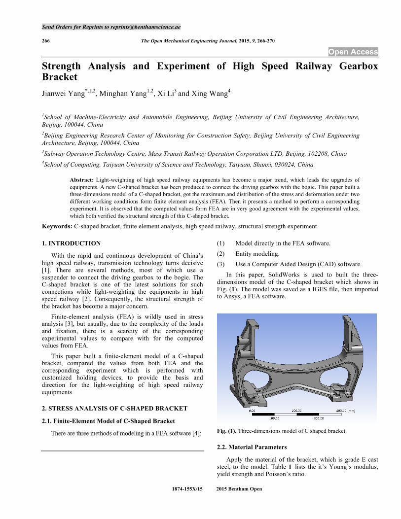
(1) Model directly in the FEA software. (2) Entity modeling. (3) Use a Computer Aided Design (CAD) software. In this paper, SolidWorks is used to built the three-dimensions model of the C-shaped bracket which shows in Fig. (1). The model was saved as a IGES file, then imported to Ansys, a FEA software.
Fig. (1). Three-dimensions model of C shaped bracket.
2.2. Material Parameters
Apply the material of the bracket, which is grade E cast steel, to the model. Table 1 lists the it’s Young’s modulus, yield strength and Poisson’s ratio.
Strength Analysis and Experiment of High Speed Railway Gearbox Bracket The Open Mechanical Engineering Journal, 2015, Volume 9 267
Table 1. Properties of grade E cast steel.
Young's Modulus Yield Strength Poisson 's Ratio
2.1 GPa 690 MPa 0.3
2.3. Boundary Conditions
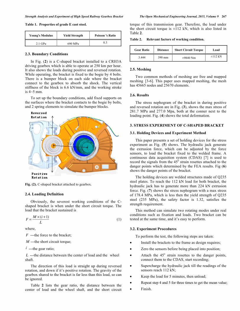
In Fig. (2) is a C-shaped bracket installed to a CRH3A driving gearbox which is able to operate at 250 km per hour. It also shows the loads during positive and reversed rotation. While operating, the bracket is fixed to the bogie by 4 bolts. There is a bumper block on each side where the bracket connect to the gearbox to absorb the shock. The vertical stiffness of the block is 6.6 kN/mm, and the working stroke is 4~5 mm. To set up the boundary conditions, add fixed supports on the surfaces where the bracket contacts to the bogie by bolts, and 2 spring elements to simulate the bumper blocks.
Fig. (2). C-shaped bracket attached to gearbox.
2.4. Loading Definition
Obviously, the severest working conditions of the C-shaped bracket is when under the short circuit torque. The load that the bracket sustained is
F = M × (i +1)L
(1)
where,
F ---the force to the bracket;
M ---the short circuit torque; i ---the gear ratio;
L ---the distance between the center of load and the wheel shaft. The direction of this load is straight up during reversed rotation, and down if it’s positive rotation. The gravity of the gearbox shared to the bracket is far less than this load, so can be ignored. Table 2 lists the gear ratio, the distance between the center of load and the wheel shaft, and the short circuit
torque of this transmission gear. Therefore, the load under the short circuit torque is ±112 kN, which is also listed in Table 2. Table 2. Relevant factors of working condition.
Gear Ratio Distance Short Circuit Torque Load
3.444 390 mm ±9840 Nm ±112 kN
2.5. Meshing
Two common methods of meshing are free and mapped meshing [3-6]. This paper uses mapped meshing, the mesh has 45665 nodes and 25670 elements.
2.6. Results
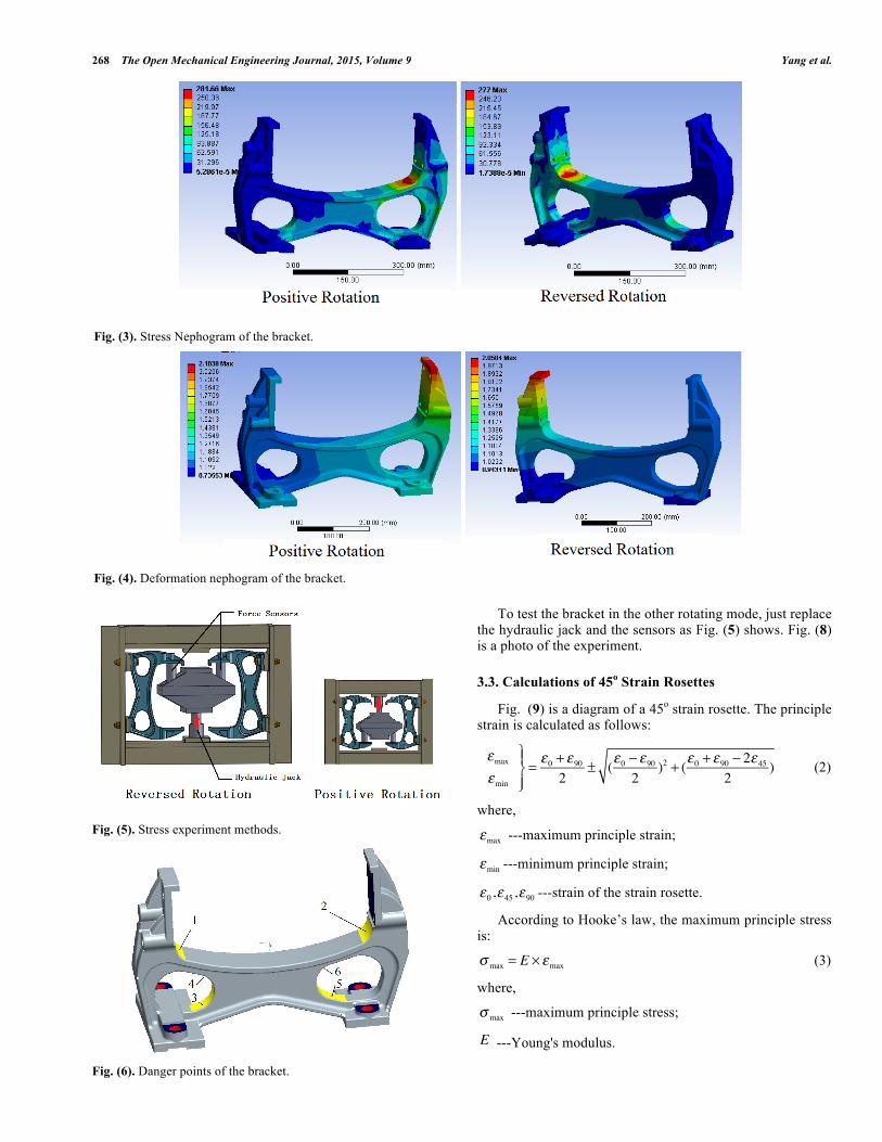
The stress nephogram of the bracket in during positive and reversed rotation are in Fig. (3), shows the max stress of 281.7 MPa and 277.0 Mpa, both at the conner next to the loading point. Fig. (4) shows the total deformation.
3. STRESS EXPERIMENT OF C-SHAPED BRACKET
3.1. Holding Devices and Experiment Method
This paper presents a set of holding devices for the stress experiment as Fig. (5) shows. The hydraulic jack generate the extrusion force, which can be adjusted by the force sensors, to load the bracket fixed to the welded frame. A continuous data acquisition system (CDAS) [7] is used to record the signals from the 45o strain rosettes attached to the danger points which determined by the FEA results. Fig (6) shows the danger points of the bracket.
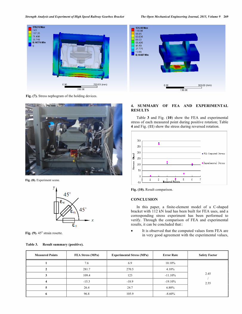
The holding devices are welded structures made of Q235 steel plates. To reach the 112 kN load for both bracket, the hydraulic jack has to generate more than 224 kN extrusion force. Fig. (7) shows the stress nephogram with a max stress of 178.4 MPa, which is less then the yield strength of Q235 steel (235 MPa), the safety factor is 1.32, satisfies the strength requirement. This method can simulate two rotating modes under real conditions such as fixation and loads. Two bracket can be tested at the same time, and it’s easy to perform.
3.2. Experiment Procedures
To perform the test, the following steps are taken: • Install the brackets to the frame as design requires; • Zero the sensors before being placed into position; • Attach the 45o strain rosettes to the danger points,
connect them to the CDAS, start recording; • Supercharge the hydraulic jack till the readings of the
sensors reach 112 kN; • Keep the load for 5 minutes, then unload; • Repeat step 4 and 5 for three times to get the mean value; • Finish.
268 The Open Mechanical Engineering Journal, 2015, Volume 9 Yang et al.
Fig. (5). Stress experiment methods.
Fig. (6). Danger points of the bracket.
To test the bracket in the other rotating mode, just replace the hydraulic jack and the sensors as Fig. (5) shows. Fig. (8) is a photo of the experiment.
3.3. Calculations of 45o Strain Rosettes
Fig. (9) is a diagram of a 45o strain rosette. The principle strain is calculated as follows:
εmaxεmin
⎫⎬⎪
⎭⎪= ε0 + ε90
2± (ε0 − ε90
2)2 + (ε0 + ε90 − 2ε45
2)
(2)
where,
εmax ---maximum principle strain;
εmin ---minimum principle strain;
ε0,ε45,ε90 ---strain of the strain rosette.
According to Hooke’s law, the maximum principle stress is:
σ max = E × εmax
(3)
where,
σ max ---maximum principle stress;
E ---Young's modulus.
Fig. (3). Stress Nephogram of the bracket.
Fig. (4). Deformation nephogram of the bracket.
Strength Analysis and Experiment of High Speed Railway Gearbox Bracket The Open Mechanical Engineering Journal, 2015, Volume 9 269
Fig. (8). Experiment scene.
Fig. (9). 45o strain rosette.
4. SUMMARY OF FEA AND EXPERIMENTAL RESULTS
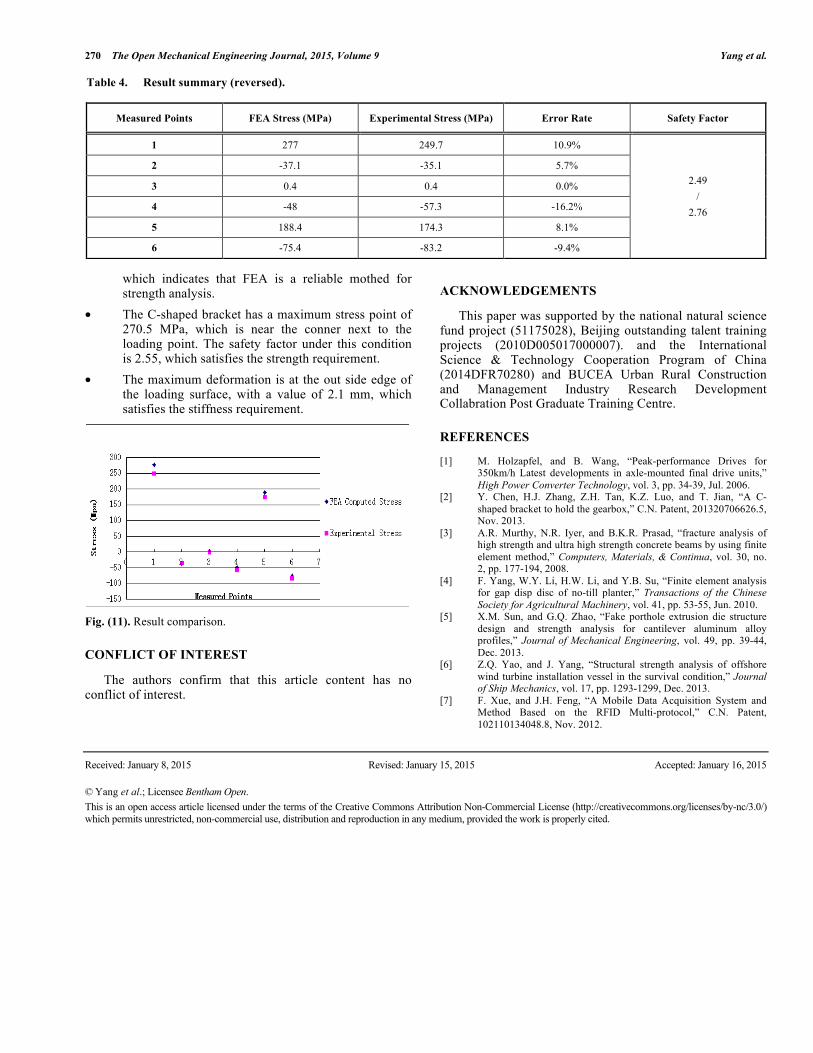
Table 3 and Fig. (10) show the FEA and experimental stress of each measured point during positive rotation; Table 4 and Fig. (11) show the stress during reversed rotation.
Fig. (10). Result comparison.
CONCLUSION
In this paper, a finite-element model of a C-shaped bracket with 112 kN load has been built for FEA uses, and a corresponding stress experiment has been performed to verify. Through the comparison of FEA and experimental results, it can be concluded that:: • It is observed that the computed values form FEA are
in very good agreement with the experimental values,
Fig. (7). Stress nephogram of the holding devices.
Table 3. Result summary (positive).
Measured Points FEA Stress (MPa) Experimental Stress (MPa) Error Rate Safety Factor
1 7.6 6.9 10.10%
2.45 /
2.55
2 281.7 270.5 4.10%
3 109.4 123 -11.10%
4 -15.3 -18.9 -19.10%
5 26.4 24.7 6.80%
6 96.8 105.9 -8.60%
270 The Open Mechanical Engineering Journal, 2015, Volume 9 Yang et al.
which indicates that FEA is a reliable mothed for strength analysis.
• The C-shaped bracket has a maximum stress point of 270.5 MPa, which is near the conner next to the loading point. The safety factor under this condition is 2.55, which satisfies the strength requirement.
• The maximum deformation is at the out side edge of the loading surface, with a value of 2.1 mm, which satisfies the stiffness requirement.
Fig. (11). Result comparison.
CONFLICT OF INTEREST
The authors confirm that this article content has no conflict of interest.
ACKNOWLEDGEMENTS
This paper was supported by the national natural science fund project (51175028), Beijing outstanding talent training projects (2010D005017000007). and the International Science & Technology Cooperation Program of China (2014DFR70280) and BUCEA Urban Rural Construction and Management Industry Research Development Collabration Post Graduate Training Centre.
REFERENCES
[1] M. Holzapfel, and B. Wang, “Peak-performance Drives for 350km/h Latest developments in axle-mounted final drive units,” High Power Converter Technology, vol. 3, pp. 34-39, Jul. 2006.
[2] Y. Chen, H.J. Zhang, Z.H. Tan, K.Z. Luo, and T. Jian, “A C-shaped bracket to hold the gearbox,” C.N. Patent, 201320706626.5, Nov. 2013.
[3] A.R. Murthy, N.R. Iyer, and B.K.R. Prasad, “fracture analysis of high strength and ultra high strength concrete beams by using finite element method,” Computers, Materials, & Continua, vol. 30, no. 2, pp. 177-194, 2008.
[4] F. Yang, W.Y. Li, H.W. Li, and Y.B. Su, “Finite element analysis for gap disp disc of no-till planter,” Transactions of the Chinese Society for Agricultural Machinery, vol. 41, pp. 53-55, Jun. 2010.
[5] X.M. Sun, and G.Q. Zhao, “Fake porthole extrusion die structure design and strength analysis for cantilever aluminum alloy profiles,” Journal of Mechanical Engineering, vol. 49, pp. 39-44, Dec. 2013.
[6] Z.Q. Yao, and J. Yang, “Structural strength analysis of offshore wind turbine installation vessel in the survival condition,” Journal of Ship Mechanics, vol. 17, pp. 1293-1299, Dec. 2013.
[7] F. Xue, and J.H. Feng, “A Mobile Data Acquisition System and Method Based on the RFID Multi-protocol,” C.N. Patent, 102110134048.8, Nov. 2012.
Received: January 8, 2015 Revised: January 15, 2015 Accepted: January 16, 2015 © Yang et al.; Licensee Bentham Open.
This is an open access article licensed under the terms of the Creative Commons Attribution Non-Commercial License (http://creativecommons.org/licenses/by-nc/3.0/) which permits unrestricted, non-commercial use, distribution and reproduction in any medium, provided the work is properly cited.
Table 4. Result summary (reversed).
Measured Points FEA Stress (MPa) Experimental Stress (MPa) Error Rate Safety Factor
1 277 249.7 10.9%
2.49 /
2.76
2 -37.1 -35.1 5.7%
3 0.4 0.4 0.0%
4 -48 -57.3 -16.2%
5 188.4 174.3 8.1%
6 -75.4 -83.2 -9.4%