Embed Size (px)
Citation preview
Slide
1
An Introduction
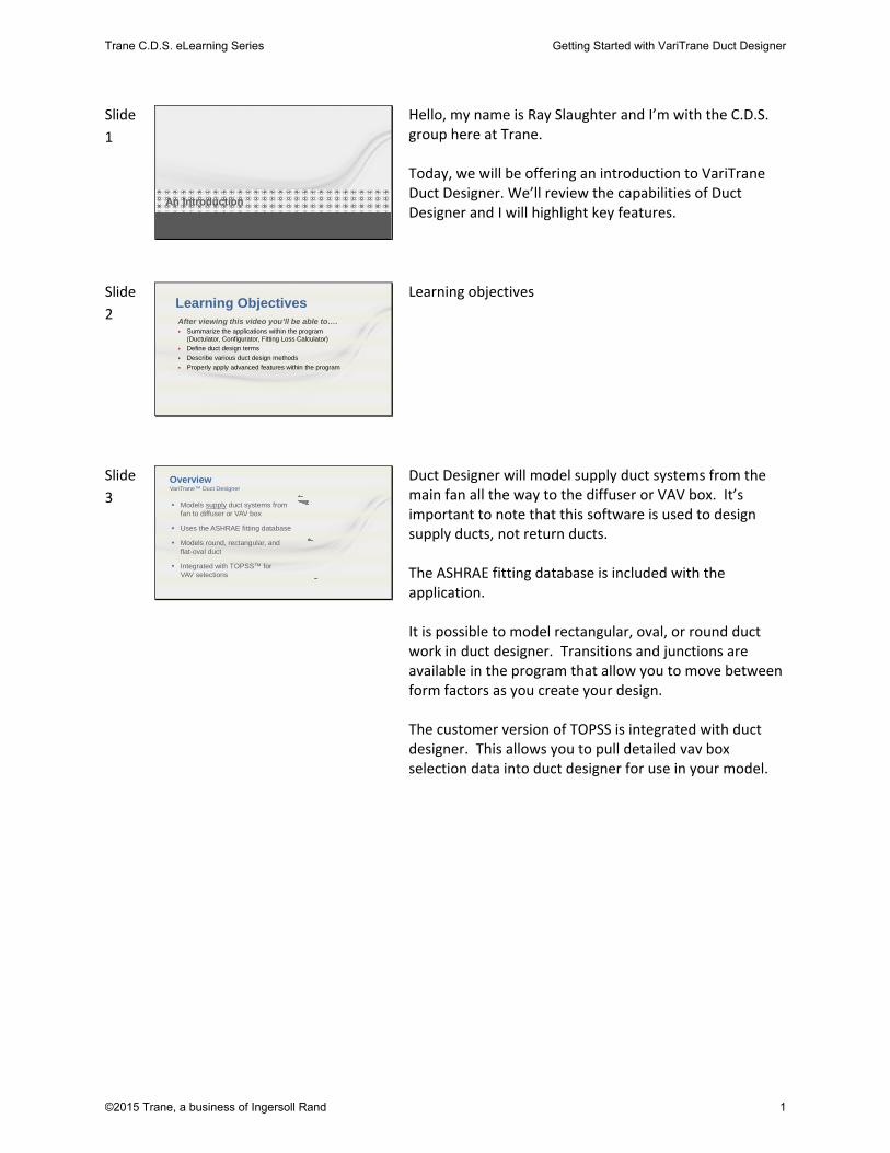
Hello, my name is Ray Slaughter and I’m with the C.D.S. group here at Trane. Today, we will be offering an introduction to VariTrane Duct Designer. We’ll review the capabilities of Duct Designer and I will highlight key features.
Slide
2 Learning ObjectivesAfter viewing this video you’ll be able to….• Summarize the applications within the program
(Ductulator, Configurator, Fitting Loss Calculator)
• Define duct design terms
• Describe various duct design methods
• Properly apply advanced features within the program
Learning objectives
Slide
3 OverviewVariTrane™ Duct Designer
• Models supply duct systems from fan to diffuser or VAV box
• Uses the ASHRAE fitting database
• Models round, rectangular, and flat-oval duct
• Integrated with TOPSS™ for VAV selections
Duct Designer will model supply duct systems from the main fan all the way to the diffuser or VAV box. It’s important to note that this software is used to design supply ducts, not return ducts. The ASHRAE fitting database is included with the application. It is possible to model rectangular, oval, or round duct work in duct designer. Transitions and junctions are available in the program that allow you to move between form factors as you create your design. The customer version of TOPSS is integrated with duct designer. This allows you to pull detailed vav box selection data into duct designer for use in your model.
Trane C.D.S. eLearning Series Getting Started with VariTrane Duct Designer
©2015 Trane, a business of Ingersoll Rand 1

Slide
4 Ductulator®
If you are accustomed to using the cardboard Ductulators, you can throw them away. Duct Designer includes an electronic version of the Ductulator for free. The electronic Ductulator is faster and easier to read. Data entry is simple and straightforward, calculation results appear almost instantly.
Slide
5 Fitting Loss Calculator
Fitting Loss Calculator computes the total pressure drop of a fitting based on its configuration, dimensions and the airflow passing through it. The calculation are based on an extensive library of fittings originating from United McGill and ASHRAE's 1993 duct fitting database. There are two ways to use Fitting Loss Calculator: 1) Within Duct Configurator to add and size fittings within duct sections. In this case, the applet opens in a window labeled Fitting Input when you click Add Inline on the Sections worksheet. 2) By itself to compare fitting efficiencies. To use the Fitting Loss Calculator this way, click or the Fitting Loss Calculator tab. Describe the fitting(s) and applicable air conditions, and the applet calculates: velocity and velocity pressure at the inlet and at each outlet, and the pressure drop and loss coefficient at each outlet
Slide
6 Duct Configurator
The Duct Configurator helps you size the supply‐duct system, identify its critical path, and determine the static pressure and the airflow required at the supply fan. If you choose, it also helps you resize non‐critical paths by identifying the fitting sizes and placement needed to balance the system. The other tabs at the bottom of the screen allow you to enter the details of your planned duct network.
Trane C.D.S. eLearning Series Getting Started with VariTrane Duct Designer
©2015 Trane, a business of Ingersoll Rand 2
Slide
7 junction
• Section
• Junction and transition fittings
• Inlet, outlet, branch
• VAV boxes vs. diffusers
• Critical path
• Auto-balancing
Terminology
fan
inlet
branch
outlet
diffuser
VAV box
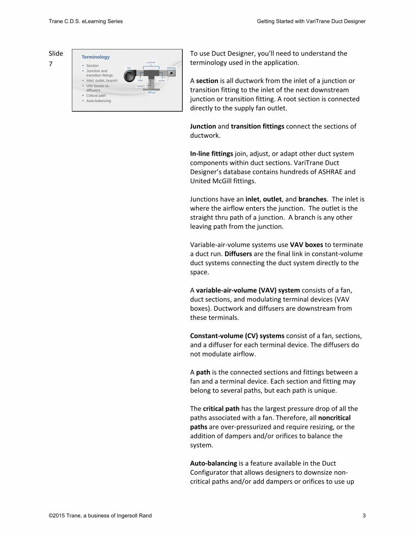
To use Duct Designer, you’ll need to understand the terminology used in the application. A section is all ductwork from the inlet of a junction or transition fitting to the inlet of the next downstream junction or transition fitting. A root section is connected directly to the supply fan outlet. Junction and transition fittings connect the sections of ductwork. In‐line fittings join, adjust, or adapt other duct system components within duct sections. VariTrane Duct Designer’s database contains hundreds of ASHRAE and United McGill fittings. Junctions have an inlet, outlet, and branches. The inlet is where the airflow enters the junction. The outlet is the straight thru path of a junction. A branch is any other leaving path from the junction. Variable‐air‐volume systems use VAV boxes to terminate a duct run. Diffusers are the final link in constant‐volume duct systems connecting the duct system directly to the space. A variable‐air‐volume (VAV) system consists of a fan, duct sections, and modulating terminal devices (VAV boxes). Ductwork and diffusers are downstream from these terminals. Constant‐volume (CV) systems consist of a fan, sections, and a diffuser for each terminal device. The diffusers do not modulate airflow. A path is the connected sections and fittings between a fan and a terminal device. Each section and fitting may belong to several paths, but each path is unique. The critical path has the largest pressure drop of all the paths associated with a fan. Therefore, all noncritical paths are over‐pressurized and require resizing, or the addition of dampers and/or orifices to balance the system. Auto‐balancing is a feature available in the Duct Configurator that allows designers to downsize non‐critical paths and/or add dampers or orifices to use up
Trane C.D.S. eLearning Series Getting Started with VariTrane Duct Designer
©2015 Trane, a business of Ingersoll Rand 3

excess pressure in the system without affecting the critical path.
Slide
8
Design Friction Rate=0.047 Determined by first trunk… unless overridden
Section LengthActual
Friction Rate Airflow Velocity DiameterActual
SP Loss Height Width0001 20 0.047 3740 991 0.0093 24 24
001A 1 0.034 3740 875 28 0.0003
0005 27 0.031 2929 794 26 0.0085
0009 27 0.036 2035 771 22 0.0098
0013 37 0.029 1059 672 18 0.0108
0015 45 0.030 550 597 14 0.0137
0023 1 0.472 550 1576 8 0.0047
Design MethodsEqual Friction: Attempts to keep the pressure drop per unit length (generally 100 ft.) of duct relatively constant throughout the system.
• Calculation revolves around the design friction rate• Typical friction rates range:
0.05 in. w.g. per 100 ft. to 0.15 in w.g. per 100 ft.
Duct Designer supports both the equal friction and static regain methods of duct design. If you have been using the Ductulator to design your duct runs, you are already familiar with the equal friction method. It attempts to keep the pressure drop per unit of duct length relatively constant throughout the system.
Slide
9
Size of section 0003 is increased until:
Static Regain: Attempts to maintain a constant static pressure throughout the duct system (a balanced system).• Calculation is limited by parameters such as minimum velocity,
fan size, and sometimes fitting selections (rectangular)• Fan outlet size is critical• Typical minimum velocity = 500 fpm….when increased the method can
actually be limited in it’s effectiveness
SPA-B = SPB-D
SPA-C = SPC-E
Size of section 0002 is increased (converting velocity pressure to static pressure) until:
Design Methods
AB D
E
C
In contrast, the static regain method attempts to maintain a constant static pressure throughout the duct system. Due to the calculations required, the static regain design method is impractical to use for hand calculations. However, it is the ideal method to use when designing a duct network on a computer.
Trane C.D.S. eLearning Series Getting Started with VariTrane Duct Designer
©2015 Trane, a business of Ingersoll Rand 4

Slide
10 Leakage Analysis
• Based on section tab entries and airflow properties
• Causes the sizing algorithm to repeat up to 11 times!– Causes all Trane VAV box selections to re-run for each repetition of
the sizing algorithm– Any error causes cancellation in box runs
Design Results: Section report Design Results: Project summary report
g
Advanced features
Duct Configurator can automatically recalculate the airflow needed at the supply fan based on how much air leaks from the system. That value, in turn, is based on the value specified for Leakage Class on the Sections worksheet.
Slide
11
Design Results: Section report Design Results: Project summary report
• Similar to leakage analysis in how this affects runtime and VAV box calculations
• Fan airflow increases for FPVAV by the same ratio as the design cooling airflow changed
• Recalculates airflow based on heat pickup
Thermal Analysis
g
Advanced features
Thermal Losses or Gains: If “Auto Correct” for “Thermal Gain/Loss” is activated, the program will take temperature change into account when sizing the duct sections. For example, if the user specifies that the air leaving the coil is 55 oF and the system picks up 5 oF before entering the space, the program will re‐calculate the new supply CFM and size the duct system based on the new “corrected” CFM. The amount of heat pick up is determined by the properties of the air in the section and the thermal U factor for each duct section. The temperature change is displayed on a section by section basis on the Design Results: Section report. The total airflow added to the system is displayed in the Project Summary report.
Slide
12 • Orifices used when over-pressurization > 1.0 in. w.g.
• Program added perforated plates have only one hole
• The “Runout Analysis” report displays the effectiveness of auto-
balancing in the “Static Over-Pressurization” column.
Note: Often restrictions within the file will prevent some paths from being completely balanced.
Every non-critical path in a duct system will be over pressurized by some amount. Auto-balancing the system inserts dampers or orifice plates in sections to equalize
the pressure in the system
Resize NCP
Auto-Balancing
Advanced features
When “Auto‐Balance” in selected by itself, the program will add dampers and adjust them in sections where over‐pressurization is present in an effort to decrease the excess static available. Perforated or orifice plates are added to sections with over‐pressurization that exceeds 1 in w.g for acoustical purposes. Dampers or plates added to the system contain the prefix “aut” in their fitting ID. To remove program added fittings from the system, uncheck the auto‐balance check box. A prompt will popup asking if the program‐added fittings should be removed. Sections can be selected to have no fittings added despite being over‐pressurized by selecting the “Don’t Add Dampers/Orifices” checkbox on the sections tab.
Trane C.D.S. eLearning Series Getting Started with VariTrane Duct Designer
©2015 Trane, a business of Ingersoll Rand 5

Slide
13 Resize NCP
• Instead of adding dampers and orifices to balance the system, non-critical path root sections are down-sized to reduce excess pressure.
• Each time a section is down-sized the entire system must be re-evaluated. This can make a file run for long periods of time.
• Since the sections sizes calculated are adjusted to standard sizes such as 8” or 10 ” and are not actual sizes the system will never be perfectly balanced. (Dampers can then be used to finish the balancing)
• Sizing restrictions can cause very limited results
Advanced features
Auto-Balancing
If “Auto‐Balance” has already been selected, “Resize Non‐Critical Paths” will become available as an option. The program will downsize the non‐critical paths of the duct system (if possible) in an effort to decrease the excess static at the terminal devices without affecting the critical path. Downsizing duct sections impact the entire system, you should expect calculation times to increase accordingly.
Slide
14 Advantages using Auto-balancing with Resize NCP
• Reduced first cost of materials
• Elimination of orifice/perforated plates in most cases
• Balanced system
Advanced features
Auto-Balancing
In other words, running this feature can reduce installation cost by reducing duct materials without affecting operating costs. Downsized sections on non‐critical paths remain within the original design constraints (i.e maximum section velocity). If some excess static still remains, dampers can further be added to finish the balancing in the system by selecting “YES” to the “Add Damper or Orifices?” drop down box.
Slide
15 VariTrane™ Duct Designer Results There are many reports available in, this is an
example of the most commonly used report in the Duct Designer. The Sections report provides many pieces of information critical to the design. Duct Designer will calculate the optimum size for a duct section, this is displayed in the Optimized Equivilent Diameter column. Since duct work is typically not produced in custom sizes down to the hundridth of an inch, DD will display the next larger standard size in the dimensions column. It’s this dimensional information that the design build contractor will need to build out the duct network. Section pressures, velocities, airflows, and inline fitting information are also available on this report.
Trane C.D.S. eLearning Series Getting Started with VariTrane Duct Designer
©2015 Trane, a business of Ingersoll Rand 6

Slide
16 Additional Resources
• VariTrane Duct Designer Getting Started Guide
• Online (F1) help
• C.D.S. Help eLearning Library
• Engineers Newsletters (Trane.com/EN)
• On-demand courses – no charge (Trane.com/ContinuingEducation)
• Trane Application Manuals (Trane.com/bookstore)
This completes our discussion on the capabilities of the Duct Design program. Hopefully, we’ve given a basic understanding of the capabilities of Duct Designer and the type of output you can expect from the applicaton. If you need assistance in other areas of the program or just want a better understanding of some of the concepts we talked about today, here are some additional resources available to you.
Slide
17
phone I 608.787.3926
fax I 608.787.3005
email I [email protected]
Web I www.tranecds.com
contact us
As always, please feel free to contact the C.D.S. Support Center by phone or email with any comments, questions or modeling concerns you have. Thank you for taking the time to learn more about Duct Designer!
Trane C.D.S. eLearning Series Getting Started with VariTrane Duct Designer
©2015 Trane, a business of Ingersoll Rand 7