Embed Size (px)
Citation preview

International Journal of Scientific & Engineering Research, Volume 7, Issue 10, October-2016 296 ISSN 2229-5518
IJSER © 2016 http://www.ijser.org
Analysis of Circular Steel Diagrid Buildings with non-Uniform Angle Configurations
Nijil George Philip1, Dr.Shashidharan.2
Abstract— Tall commercial buildings are primarily a response to the intense pressure on the available land. Advances in materials, construction technology, analytical methods and structural systems for analysis and design accelerated the development of tall structures. The lateral loading due to wind and earthquake is the major factor that causes the design of high-rise buildings. These lateral loads are resisted by exterior structural system or interior structural system. Diagrid is an exterior structural system emerging as structurally efficient as well as architecturally significant assemblies for tall buildings. Diagrid eliminated all vertical columns and consists of only inclined columns on the façade of the building. Shear and over-turning moment developed are resisted by axial action of these diagonals compared to bending of vertical columns in framed tube structure. These inclined columns or diagonals have an optimal angle at which the structural capability of the member is optimized for both gravity and lateral loadings. In this paper, circular buildings configured with uniform diagonal angle are compared to buildings with non-uniform diagrid angle distribution. A regular plan diameter of 40.63 m was considered for the building. ETABS software is used for modelling and analysis of structural members. 36, 50, 60, 70 and 80 storey buildings are modelled with uniform and non-uniform diagrid angle configurations. Dynamic wind analysis have carried out as per Gust effect factor method of IS:875 Part III- 1987. Comparison of analysis results in terms of top storey displacement and maximum forces developed on the diagrid member is presented in this paper.
Index Terms—Tall building, steel structures, diagrids, wind analysis, circular plan buildings.
————————————————————
1 INTRODUCTION
ALL buildings have developed in response to the re-quirements arising from the continuing increase in world population, scarcity and high cost of land. Advances in
construction technology, materials, structural systems, analy-sis and design software facilitated the growth of tall buildings. When the height of building increases, the lateral load resist-ing system plays important role than the structural system that resists the gravitational loads. The lateral load resisting systems that are widely used are mainly rigid frame, shear wall, wall-frame, braced tube system, outrigger system and tubular system. Recent trend shows that the Diagrid structural system is becoming popular in the design of tall buildings due to its inherent structural and architectural advantages.
Diagrid consists of perimeter grid made up of a series of triangulated truss system. Diagrids are generally stiffer than equivalently designed tubular structures, and provide more efficient use of material. It uses an exclusive exterior frame comprised entirely of diagonal members, eliminating the ver-tical columns. Vertical columns in the core are capable only of withstanding gravity loads and the diagrid is useful for both gravity and lateral loading. This type of structure carries lat-eral wind loads more efficiently, creating stiffness that is com-plemented by the axial action of the diagonal member. The famous examples of diagrid structure all around the world are the Hearst Tower in New York, Swiss Re in London, Capital Gate Tower in Abu Dhabi, and Aldar Headquarters, Abu Dhabi as shown in fig 1.
T
———————————————— • Nijil George Philip is currently pursuing masters degree program in NSS
College of Engineering, Palakkad, India PH- +917560803050. E-mail: [email protected]
• Dr. Shashidharanis Professor in NSS College of Engineering, Palakkad, India PH- +919447577645. E-mail: [email protected]
IJSER

International Journal of Scientific & Engineering Research, Volume 7, Issue 10, October-2016 297 ISSN 2229-5518
IJSER © 2016
http://www.ijser.org
Fig.1. Diagrid buildings (a) Hearst Tower in New York, (b) Swiss Re in London, (c) Capital Gate Tower in Abu Dhabi, (d) Aldar Headquarters, Abu Dhabi.
Moon et al focused their study of diagrid structures on 60
storey building because majority of world’s largest buildings fall between 50 and 70 stories. They discovered the optimal angle for the diagrid to be 35˚ when considering shear rigidity compared to 90˚ optimal angle any for maximum bending ri-gidity. So concluded that for any diagrid building optimum angle lies somewhere between this two values.
Most of the diagrid buildings are using the optimal di-agonal angle or an angle close to the optimal value along the height of the building. When the building is taller, the bending is predominant than shear towards the bottom of the building while shear dominates at the top portion. The responses of the diagrid building could be reduced, if the building is provided with non-uniform diagrid angle configurations. In this paper diagrid buildings of circular plan of various aspect ratio and diagrid configurations are analysed. A comparative study is carried out on analysis results in terms of top storey displace-ment and maximum forces acting on diagrid members.
2 MODELLING AND ANALYSIS 2.1 Building configuration
Diagrid buildings of 36, 50, 60, 70 and 80 storeys height are selected for the study. Circular buildings having plan di-ameter of 40.63 m are modelled and analysed with uniform diagrid angle and non-uniform diagrid angle patterns. The typical plan of circular buildings are shown in fig. 2. The sto-rey height is 3.6 m. The spacing between diagrid members is fixed as 6 m. For the uniform diagrid angle buildings, the an-gle of inclination is kept uniform throughout the height. For non-uniform diagrid buildings, the diagonal angle changed along the height of the building.
Fig.2: Typical plan for the Circular building The dead load and live loads on floor slab are 3.75 kN/m2 and 2.5 kN/m2 respectively. The dynamic along wind loading is computed based on the basic wind speed of 30 m/sec and ter-rain category III as per IS:875 (III)-1987 (Gust factor method). Load combinations as per IS:800-2005 are applied. Modelling and analysis of diagrid structure are carried out using ETABS software. Beams and columns are modelled by beam elements and braces are modelled by truss elements. The support condi-tions are assumed as hinged.
2.2 Modelling and analysis of 36 storey diagrid buildings Four models of the circular buildings are developed for
the study of the response of 36 storey buildings. The aspect ratio of the building is 3.20.
Fig.3 : Diagrid angle distribution of different 36 storey build-ings.
IJSER

International Journal of Scientific & Engineering Research, Volume 7, Issue 10, October-2016 298 ISSN 2229-5518
IJSER © 2016
http://www.ijser.org
Fig.4: Extruded view of model 36 A
The first configuration having diagrid angle uni-
formly distributed along the height. The diagrid angle is close to the optimum value of the building. The second configura-tion is having its diagrid angle changes from 82 to 50 degree from bottom to top of the building. In the third model diagrid angle changes from 78 to 50 degree. In fourth configuration, the diagrid angle changes from 75 to 50 degree. The distribu-tion of diagrid angle of different models are shown in fig.3. Circular diagrid building models are named as 36 A, 36 B, 36 C and 36 D respectively. Each models are analysed and the responses are studied. Maximum storey displacement and the maximum force on the diagrid member is considered for the study. The configuration which provide minimum displace-ment and stresses are noted. The graph for the building which develop minimum displacements is given in the fig.5.
Fig.5: Displacement plot for Model 36 A 2.3 Modelling and analysis of 50 storey diagrid building
Fig.6: Diagrid angle distribution of different 50 storey build-ings. The circular buildings having height of 50 stories were mod-elled and analysed. The aspect ratio of the building is 4.43. Four models of the circular buildings are developed for the study of the response of 50 storey building. The building models are named as 50 A, 50 B, 50 C and 50 D respectively. The distribution of diagrid angle of different models are
shown in fig.6.
Fig.7: Extruded view of model 50 A
Fig.8: Displacement plot for Model 50 A
Each models are analysed and the responses are studied.
Maximum storey displacement and the maximum force on the diagrid member is considered for the study. The configuration which provide minimum displacement and stresses are noted. The graph for the building which develop minimum dis-placements is given in the fig.8.
IJSER

International Journal of Scientific & Engineering Research, Volume 7, Issue 10, October-2016 299 ISSN 2229-5518
IJSER © 2016
http://www.ijser.org
2.4 Modelling and analysis of 60 storey diagrid build-ings
The circular buildings having height of 60 stories were modelled and analysed. The aspect ratio of the building is 5.32. Four models of the circular buildings are developed for the study of the response of 60 storey building. The building models are named as 60 A, 60 B, 60 C and 60 D respectively. The distribution of diagrid angle of different models of 60 sto-rey buildings are shown in fig.9.
Fig.9: Diagrid angle distribution of different 60 storey build-ings.
Fig.10: 3D view of model 60 D
Each models are analysed and the responses are studied. Maximum storey displacement and the maximum force on the diagrid member is considered for the study. The configuration which provide minimum displacement and stresses are noted. The graph for the building which develop minimum dis-placements is given in the fig.11.
Fig.11: Displacement plot for Model 60 D 2.5 Modelling and analysis of 70 storey diagrid build-
ings Fig.12: Diagrid angle distribution of different 70 storey build-ings.
The buildings having height of 70 stories were modelled
and analysed. The aspect ratio of the building is 6.20. Four
IJSER

International Journal of Scientific & Engineering Research, Volume 7, Issue 10, October-2016 300 ISSN 2229-5518
IJSER © 2016
http://www.ijser.org
models of the circular buildings are developed for the study of the response of 70 storey building. The building models are named as 70 A, 70 B, 70 C and 70 D respectively. The distribu-tion of diagrid angle of different models of 70 storey buildings are shown in fig.12.
Fig.13: 3D view of model 70 D
Fig.14: Displacement plot for Model 70 D Each models are analysed and the responses are studied.
Maximum storey displacement and the maximum force on the diagrid member is considered for the study. The configuration which provide minimum displacement and stresses are noted. The graph for the building which develop minimum dis-placements is given in the fig.14.
2.6 Modelling and analysis of 80 storey diagrid build-ings
The circular shaped buildings having height of 80 stories were modelled and analysed. The aspect ratio of the building is 7.0. Four models of the circular buildings are developed for the study of the response of 80 storey building. The building models are named as 80 A, 80 B, 80 C and 80 D respectively. The distribution of diagrid angle of different models of 80 sto-rey buildings are shown in fig.15. Fig.15: Diagrid angle distribution of different 80 storey build-ings.
Fig.16: 3D view of model 80 D
IJSER
International Journal of Scientific & Engineering Research, Volume 7, Issue 10, October-2016 301 ISSN 2229-5518
IJSER © 2016
http://www.ijser.org
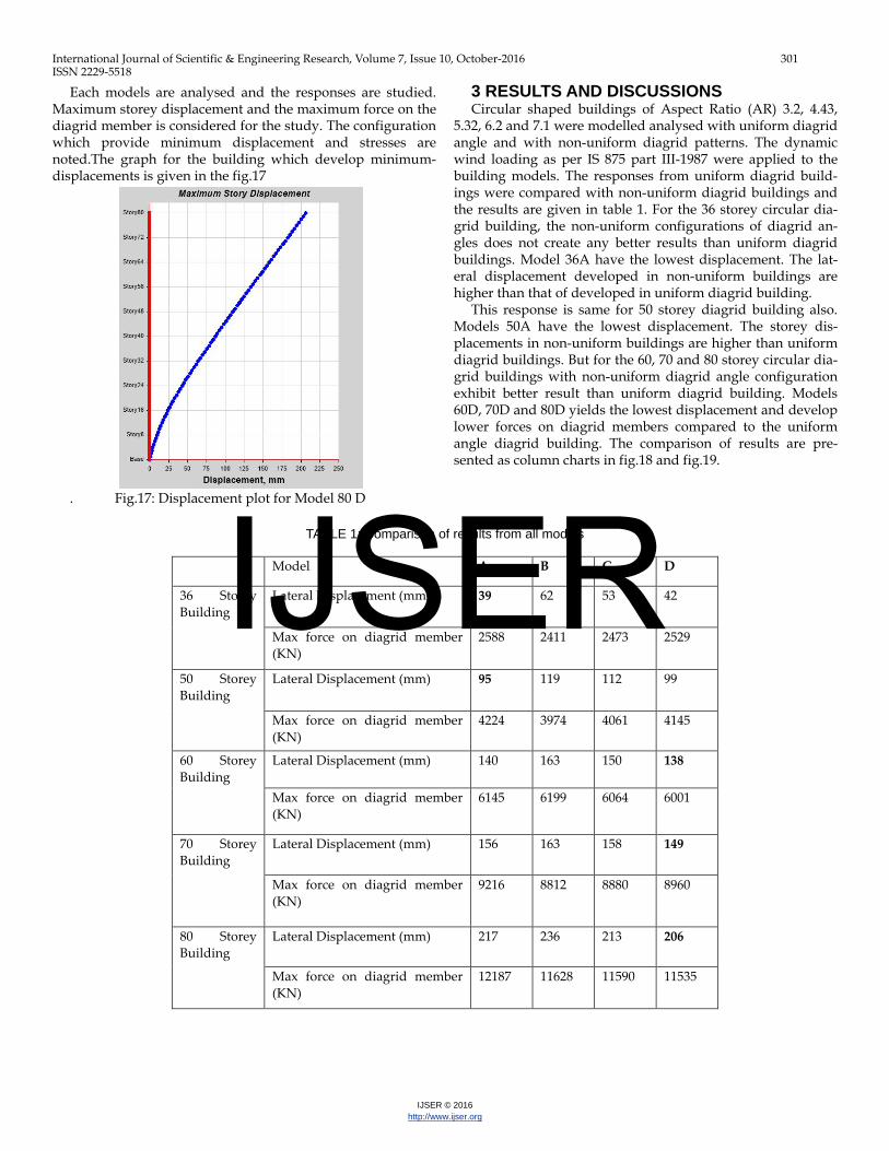
Each models are analysed and the responses are studied. Maximum storey displacement and the maximum force on the diagrid member is considered for the study. The configuration which provide minimum displacement and stresses are noted.The graph for the building which develop minimum-displacements is given in the fig.17
. Fig.17: Displacement plot for Model 80 D
3 RESULTS AND DISCUSSIONS Circular shaped buildings of Aspect Ratio (AR) 3.2, 4.43,
5.32, 6.2 and 7.1 were modelled analysed with uniform diagrid angle and with non-uniform diagrid patterns. The dynamic wind loading as per IS 875 part III-1987 were applied to the building models. The responses from uniform diagrid build-ings were compared with non-uniform diagrid buildings and the results are given in table 1. For the 36 storey circular dia-grid building, the non-uniform configurations of diagrid an-gles does not create any better results than uniform diagrid buildings. Model 36A have the lowest displacement. The lat-eral displacement developed in non-uniform buildings are higher than that of developed in uniform diagrid building.
This response is same for 50 storey diagrid building also. Models 50A have the lowest displacement. The storey dis-placements in non-uniform buildings are higher than uniform diagrid buildings. But for the 60, 70 and 80 storey circular dia-grid buildings with non-uniform diagrid angle configuration exhibit better result than uniform diagrid building. Models 60D, 70D and 80D yields the lowest displacement and develop lower forces on diagrid members compared to the uniform angle diagrid building. The comparison of results are pre-sented as column charts in fig.18 and fig.19.
TABLE 1: Comparison of results from all models
Model A B C D
36 Storey Building
Lateral Displacement (mm) 39 62 53 42
Max force on diagrid member (KN)
2588 2411 2473 2529
50 Storey Building
Lateral Displacement (mm) 95 119 112 99
Max force on diagrid member (KN)
4224 3974 4061 4145
60 Storey Building
Lateral Displacement (mm) 140 163 150 138
Max force on diagrid member (KN)
6145 6199 6064 6001
70 Storey Building
Lateral Displacement (mm) 156 163 158 149
Max force on diagrid member (KN)
9216 8812 8880 8960
80 Storey Building
Lateral Displacement (mm) 217 236 213 206
Max force on diagrid member (KN)
12187 11628 11590 11535
IJSER

International Journal of Scientific & Engineering Research, Volume 7, Issue 10, October-2016 302 ISSN 2229-5518
IJSER © 2016
http://www.ijser.org
Fig18: Storey Displacement for different models.
Fig.19: Maximum force on diagrid for different models
4 CONCLUSIONS In this paper, circular diagrid buildings of different angle con-figurations were modelled and analysed. The plan diameter considered for the circular building was 40.63 m. 36, 50, 60, 70 and 80 storey buildings are modelled with uniform and non-uniform diagrid angle configurations. A comparative study was conducted between the results obtained from 20 models in terms of top storey displacement and maximum forces de-veloped on the diagrid member. The following conclusions can be inferred from the study. • Circular building of 36 and 50 storeys yield lowest dis-
placement when configured with uniform diagrid angle. • In 60, 70 and 80 storey buildings, non-uniform diagrid
configuration provided lower displacement and diagrid forces when the diagrid angle changed from 75° to 50°. The forces on diagrids reduced around 2.5%, 3% and 5.5% in 60, 70 and 80 storey buildings respectively.
• From these observations, it could be assumed that use of non-uniform diagrid configurations of specified angles, would reduce the forces on diagrids in circular buildings having aspect ratio 5.30 and above. So designing the dia-
grid building with changing diagrid angle could reduce the section size required and thereby reduce the material required for the building.
5 REFERENCES
[1] Ali M. M, Moon K (2007), “Structural Developments in Tall Buildings: Current Trends and Future Prospects”; Arc-hitectural Science Review, Vol. 50.3, pp. 205-223.
[2] Boake T.M (2014); “Diagrid Structures: Innovation and Detailing”, Journal of Engineering Structures.
[3] Elena Mele, Maurizio Toreno, Giuseppe Brandonisio, Antonello De Luca (2014), “Diagrid structures for tall build-ings: case studies and design considerations”, The structural design of tall and special buildings,23, 124-145.
[4] Giovanni Maria Montuori (et.al) (2014)a, “Geometric-al patterns for diagrid buildings: Exploring alternative design strategies from the structural point of view” ; Engineering Structures , 71, 112–127.
[5] Giovanni Maria Montuori (et.al) (2014)b, “Secondary bracing systems for diagrid structures in tall buildings” ; En-gineering Structures , 75, 477-488.
[6] IS: 800 (2005), “General Construction in Steel — Code of Practice”, Bureau of Indian Standards.
[7] IS: 875 Part III (1987), “Code of practice for design
IJSER

International Journal of Scientific & Engineering Research, Volume 7, Issue 10, October-2016 303 ISSN 2229-5518
IJSER © 2016
http://www.ijser.org
loads (other than earthquake) for buildings and structures”, Bureau of Indian Standards.
[8] KVS Chandra Sekhar and Vinay K Gupta (1996), “A note on IS: 875 -1987 approach to along-wind building re-sponse”, Journal of Structural Engineering, Vol. 23, No 3, 121-127.
[9] Moon K (2009), “Design and Construction of Steel Di-agrid Structures”, Journal of Constructional Steel Research, 96, 453–534.
[10] KhushbuJani, Paresh V. Patel (2013); “Analysis and Design of Diagrid Structural System for High Rise Steel Build-ings.” ;Procedia Engineering, 5, 92 – 100.
[11] Kyoung-Sun Moon (2011), “Diagrid Structures for Complex-Shaped Tall Buildings”, Procedia Engineering 14, 1343–1350.
[12] Kyoung-Sun Moon (2010), “Stiffness based design methodology for steel braced tube structures : A sustainable approach” , Journal of Engineering Structures, 32, 3163-3170.
[13] Kyoung-Sun Moon, Jerome J. Connor, John E. Fer-nandez (2007), “Diagrid structural systems for tall buildings: characteristics and methodology for preliminary design”, Journal of Structural Design Of Tall And Special Buildings 16, 205–230.
IJSER


![Pre-Engineered Buildings Structural Steel Buildings ...€¦ · Pre-Engineered Buildings Structural Steel Buildings LEADERS IN THE STEEL BUILDINGS INDUSTRY mKÁúeTsk_ vis½y]sSahkmµ](https://img.pdfslide.net/doc/110x75/5f069e707e708231d418e449/pre-engineered-buildings-structural-steel-buildings-pre-engineered-buildings.jpg)