Embed Size (px)
Citation preview
6: Wireless and Mobile Networks 6-1
Chapter 6Wireless and Mobile Networks
A note on the use of these ppt slides:We’re making these slides freely available to all (faculty, students, readers). They’re in PowerPoint form so you can add, modify, and delete slides (including this one) and slide content to suit your needs. They obviously represent a lot of work on our part. In return for use, we only ask the following: If you use these slides (e.g., in a class) in substantially unaltered form, that you mention their source (after all, we’d like people to use our book!) If you post any slides in substantially unaltered form on a www site, that you note that they are adapted from (or perhaps identical to) our slides, and note our copyright of this material.
Thanks and enjoy! JFK/KWR
All material copyright 1996-2007J.F Kurose and K.W. Ross, All Rights Reserved
Computer Networking: A Top Down Approach 4th edition. Jim Kurose, Keith RossAddison-Wesley, July 2007.
Adapted by Andreas Pitsillides for class EPL324, Computer Science department, University of Cyprus, from Kurose and Ross slides: see below
6: Wireless and Mobile Networks 6-2
Chapter 6: Wireless and Mobile Networks
Background: # wireless (mobile) phone subscribers now
exceeds # wired phone subscribers! See trends
computer nets: laptops, palmtops, PDAs, Internet-enabled phone promise anytime untethered Internet access
two important (but different) challenges wireless: communication over wireless link mobility: handling the mobile user who changes point
of attachment to network
6: Wireless and Mobile Networks 6-3
Chapter 6 outline
6.1 Introduction
Wireless 6.2 Wireless links,
characteristics CDMA
6.3 IEEE 802.11 wireless LANs (“wi-fi”)
6.4 Cellular Internet Access architecture standards (e.g., GSM)
Mobility 6.5 Principles:
addressing and routing to mobile users
6.6 Mobile IP 6.7 Handling mobility in
cellular networks 6.8 Mobility and higher-
layer protocols
6.9 Summary
6: Wireless and Mobile Networks 6-4
Elements of a wireless network: wireless host
network infrastructure
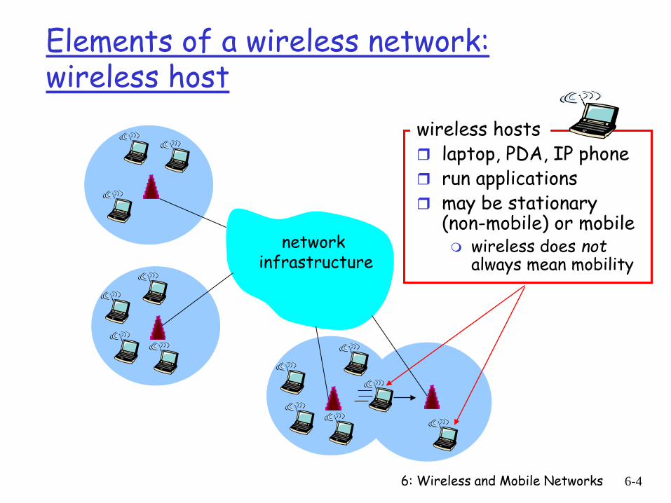
wireless hosts laptop, PDA, IP phone run applications may be stationary
(non-mobile) or mobile wireless does not
always mean mobility
6: Wireless and Mobile Networks 6-5
Elements of a wireless network : base station
network infrastructure
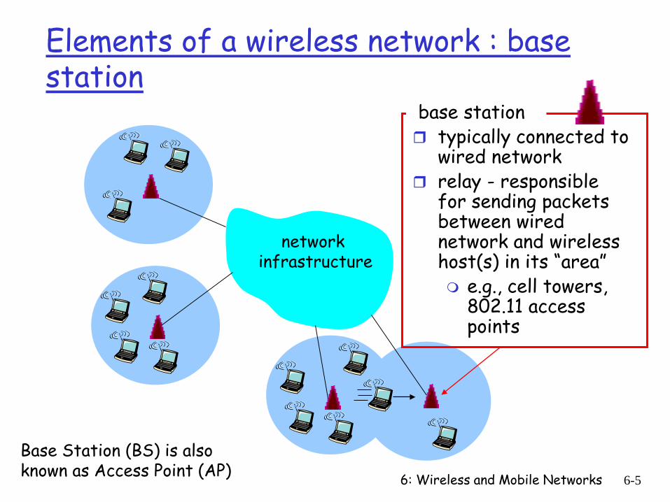
base station typically connected to
wired network relay - responsible
for sending packets between wired network and wireless host(s) in its “area” e.g., cell towers,
802.11 access points
Base Station (BS) is also known as Access Point (AP)
6: Wireless and Mobile Networks 6-6
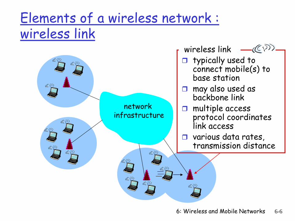
Elements of a wireless network : wireless link
network infrastructure
wireless link typically used to
connect mobile(s) to base station
may also used as backbone link
multiple access protocol coordinates link access
various data rates, transmission distance

6: Wireless and Mobile Networks 6-7
Characteristics of selected wireless link standards
Indoor10-30m
Outdoor50-200m
Mid-rangeoutdoor
200m – 4 Km
Long-rangeoutdoor
5Km – 20 Km
.056
.384
1
4
5-11
54
IS-95, CDMA, GSM 2G
UMTS/WCDMA, CDMA2000 3G
802.15
802.11b
802.11a,g
UMTS/WCDMA-HSPDA, CDMA2000-1xEVDO 3G cellularenhanced
802.16 (WiMAX), LTE, LTE enhanced
802.11a,g point-to-point
200 802.11n
Dat
a ra
te (M
bps) data
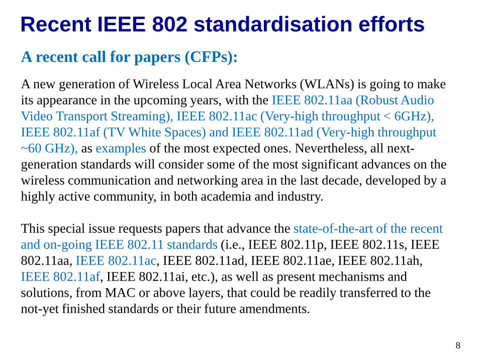
A recent call for papers (CFPs):A new generation of Wireless Local Area Networks (WLANs) is going to make its appearance in the upcoming years, with the IEEE 802.11aa (Robust Audio Video Transport Streaming), IEEE 802.11ac (Very-high throughput < 6GHz), IEEE 802.11af (TV White Spaces) and IEEE 802.11ad (Very-high throughput ~60 GHz), as examples of the most expected ones. Nevertheless, all next-generation standards will consider some of the most significant advances on the wireless communication and networking area in the last decade, developed by a highly active community, in both academia and industry.
This special issue requests papers that advance the state-of-the-art of the recent and on-going IEEE 802.11 standards (i.e., IEEE 802.11p, IEEE 802.11s, IEEE 802.11aa, IEEE 802.11ac, IEEE 802.11ad, IEEE 802.11ae, IEEE 802.11ah, IEEE 802.11af, IEEE 802.11ai, etc.), as well as present mechanisms and solutions, from MAC or above layers, that could be readily transferred to the not-yet finished standards or their future amendments.
Recent IEEE 802 standardisation efforts
8
6: Wireless and Mobile Networks 6-9
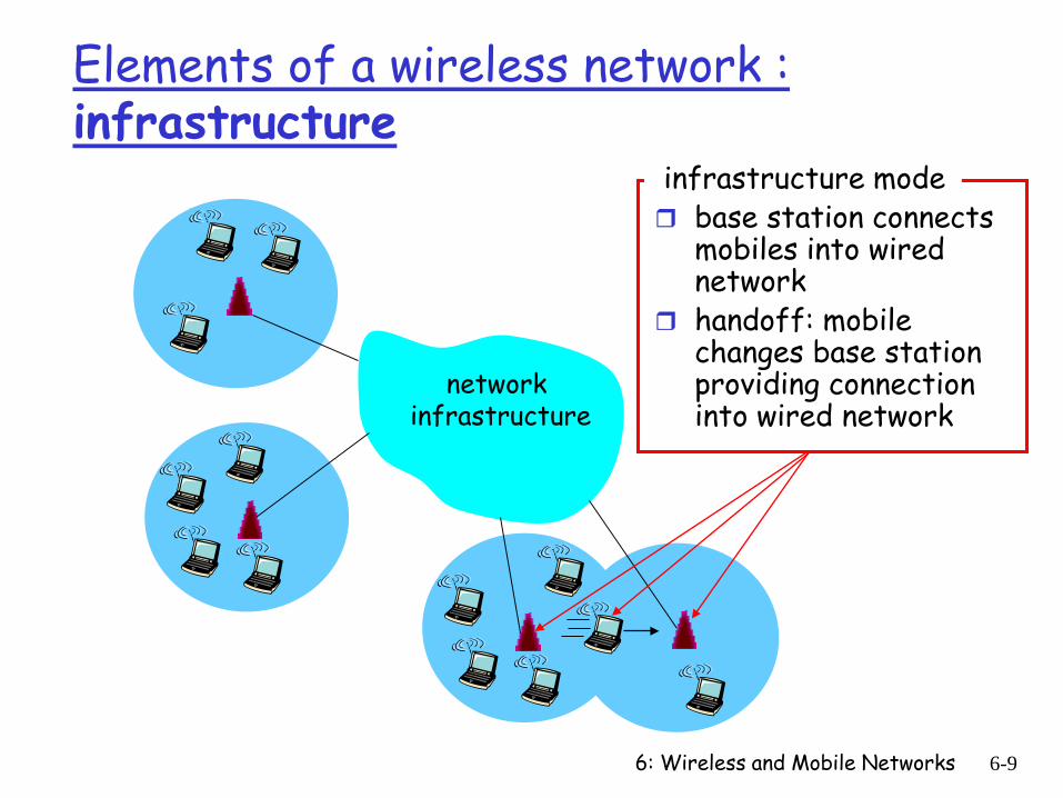
Elements of a wireless network : infrastructure
network infrastructure
infrastructure mode base station connects
mobiles into wired network
handoff: mobile changes base station providing connection into wired network
6: Wireless and Mobile Networks 6-10
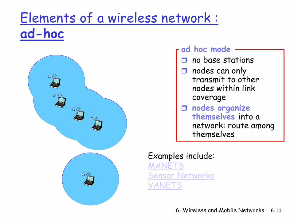
Elements of a wireless network : ad-hoc
ad hoc mode no base stations nodes can only
transmit to other nodes within link coverage
nodes organize themselves into a network: route among themselves
Examples include: MANETSSensor NetworksVANETS
6: Wireless and Mobile Networks 6-11
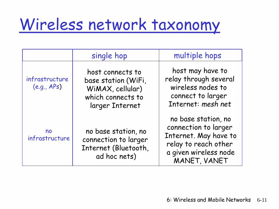
Wireless network taxonomy
single hop multiple hops
infrastructure(e.g., APs)
noinfrastructure
host connects to base station (WiFi,WiMAX, cellular) which connects to
larger Internet
no base station, noconnection to larger Internet (Bluetooth,
ad hoc nets)
host may have torelay through several
wireless nodes to connect to larger
Internet: mesh net
no base station, noconnection to larger
Internet. May have torelay to reach other a given wireless node
MANET, VANET
6: Wireless and Mobile Networks 6-12
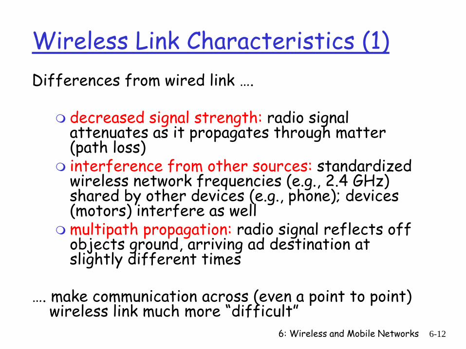
Wireless Link Characteristics (1)Differences from wired link ….
decreased signal strength: radio signal attenuates as it propagates through matter (path loss)
interference from other sources: standardized wireless network frequencies (e.g., 2.4 GHz) shared by other devices (e.g., phone); devices (motors) interfere as well
multipath propagation: radio signal reflects off objects ground, arriving ad destination at slightly different times
…. make communication across (even a point to point) wireless link much more “difficult”
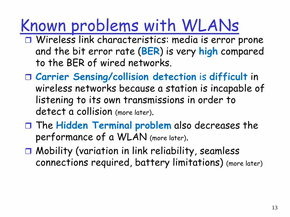
Known problems with WLANs Wireless link characteristics: media is error prone
and the bit error rate (BER) is very high compared to the BER of wired networks.
Carrier Sensing/collision detection is difficult in wireless networks because a station is incapable of listening to its own transmissions in order to detect a collision (more later).
The Hidden Terminal problem also decreases the performance of a WLAN (more later).
Mobility (variation in link reliability, seamless connections required, battery limitations) (more later)
13
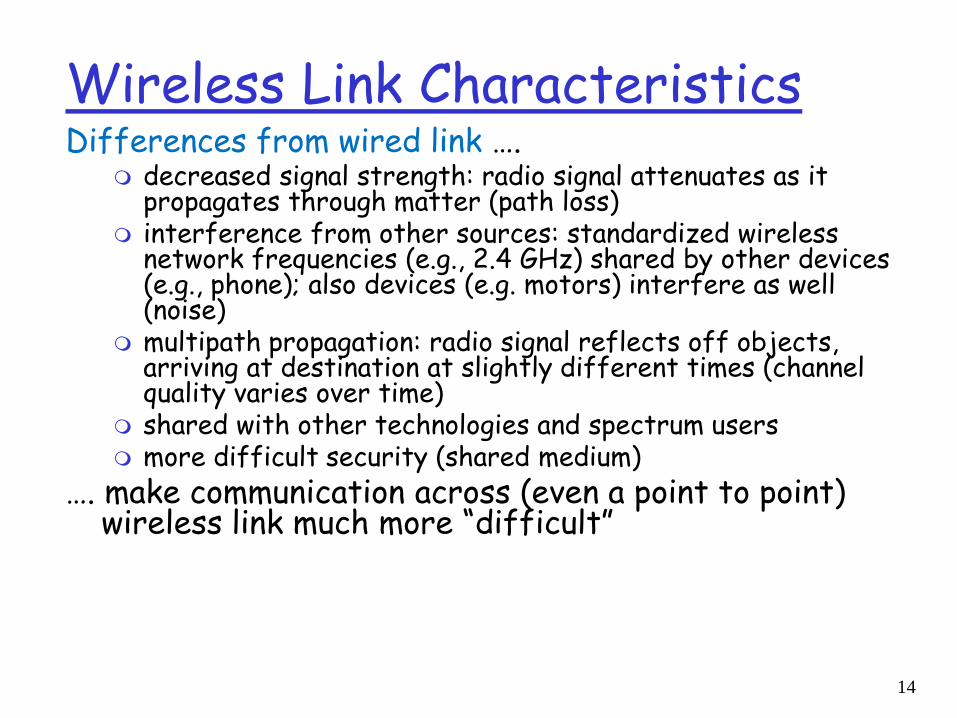
Wireless Link CharacteristicsDifferences from wired link ….
decreased signal strength: radio signal attenuates as it propagates through matter (path loss)
interference from other sources: standardized wireless network frequencies (e.g., 2.4 GHz) shared by other devices (e.g., phone); also devices (e.g. motors) interfere as well (noise)
multipath propagation: radio signal reflects off objects, arriving at destination at slightly different times (channel quality varies over time)
shared with other technologies and spectrum users more difficult security (shared medium)
…. make communication across (even a point to point) wireless link much more “difficult”
14
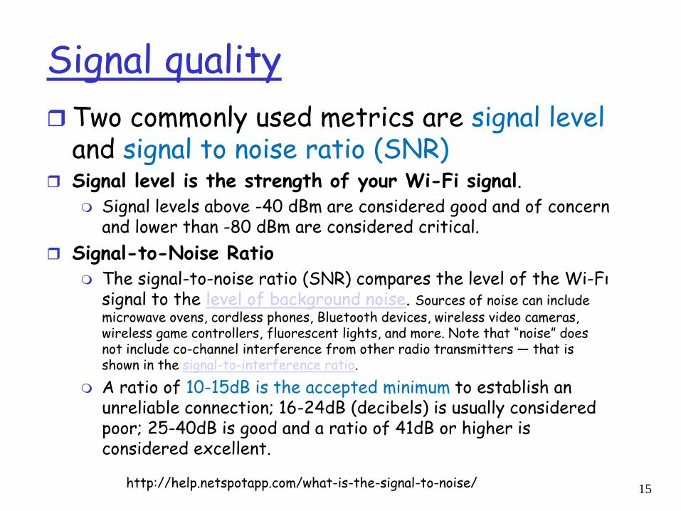
Signal quality Two commonly used metrics are signal level
and signal to noise ratio (SNR) Signal level is the strength of your Wi-Fi signal.
Signal levels above -40 dBm are considered good and of concern and lower than -80 dBm are considered critical.
Signal-to-Noise Ratio The signal-to-noise ratio (SNR) compares the level of the Wi-Fι
signal to the level of background noise. Sources of noise can include microwave ovens, cordless phones, Bluetooth devices, wireless video cameras, wireless game controllers, fluorescent lights, and more. Note that “noise” does not include co-channel interference from other radio transmitters — that is shown in the signal-to-interference ratio.
A ratio of 10-15dB is the accepted minimum to establish an unreliable connection; 16-24dB (decibels) is usually considered poor; 25-40dB is good and a ratio of 41dB or higher is considered excellent.
http://help.netspotapp.com/what-is-the-signal-to-noise/ 15
6: Wireless and Mobile Networks 6-16
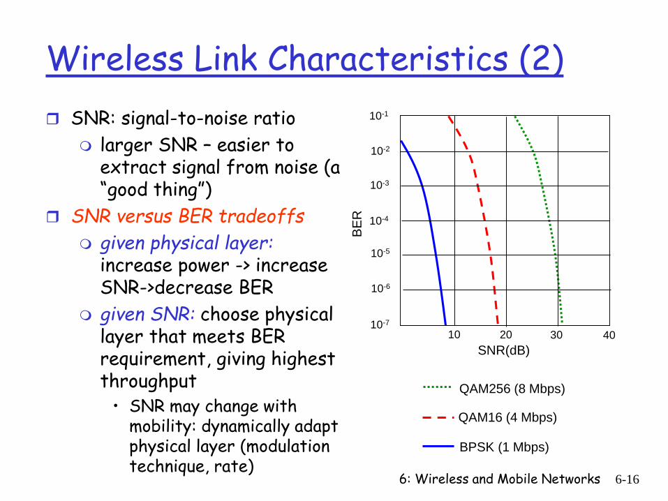
Wireless Link Characteristics (2) SNR: signal-to-noise ratio
larger SNR – easier to extract signal from noise (a “good thing”)
SNR versus BER tradeoffs given physical layer:
increase power -> increase SNR->decrease BER
given SNR: choose physical layer that meets BER requirement, giving highest throughput
• SNR may change with mobility: dynamically adapt physical layer (modulation technique, rate)
10 20 30 40
QAM256 (8 Mbps)
QAM16 (4 Mbps)
BPSK (1 Mbps)
SNR(dB)BE
R
10-1
10-2
10-3
10-5
10-6
10-7
10-4
6: Wireless and Mobile Networks 6-17
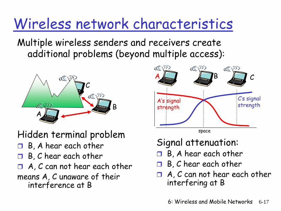
Wireless network characteristicsMultiple wireless senders and receivers create
additional problems (beyond multiple access):
AB
C
Hidden terminal problem B, A hear each other B, C hear each other A, C can not hear each othermeans A, C unaware of their
interference at B
A B C
A’s signalstrength
space
C’s signalstrength
Signal attenuation: B, A hear each other B, C hear each other A, C can not hear each other
interfering at B
6: Wireless and Mobile Networks 6-18
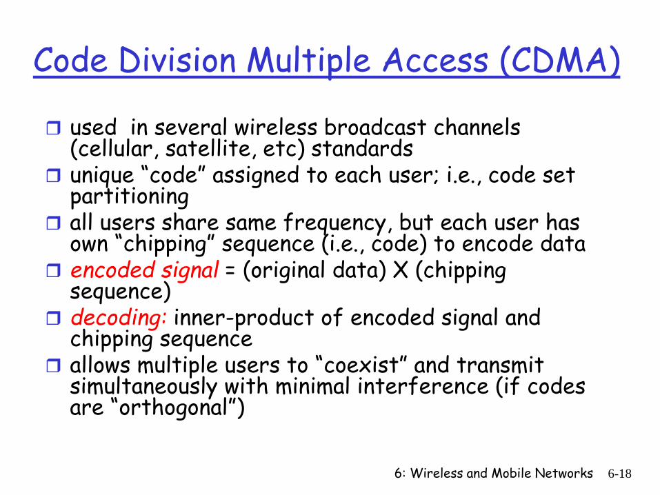
Code Division Multiple Access (CDMA)
used in several wireless broadcast channels (cellular, satellite, etc) standards
unique “code” assigned to each user; i.e., code set partitioning
all users share same frequency, but each user has own “chipping” sequence (i.e., code) to encode data
encoded signal = (original data) X (chipping sequence)
decoding: inner-product of encoded signal and chipping sequence
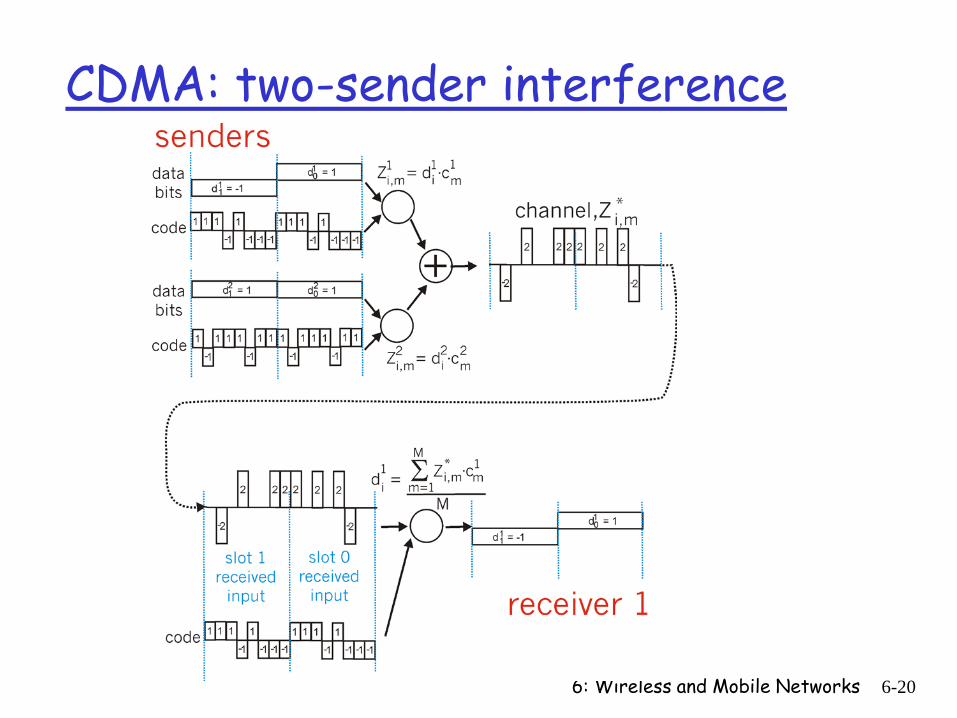
allows multiple users to “coexist” and transmit simultaneously with minimal interference (if codes are “orthogonal”)
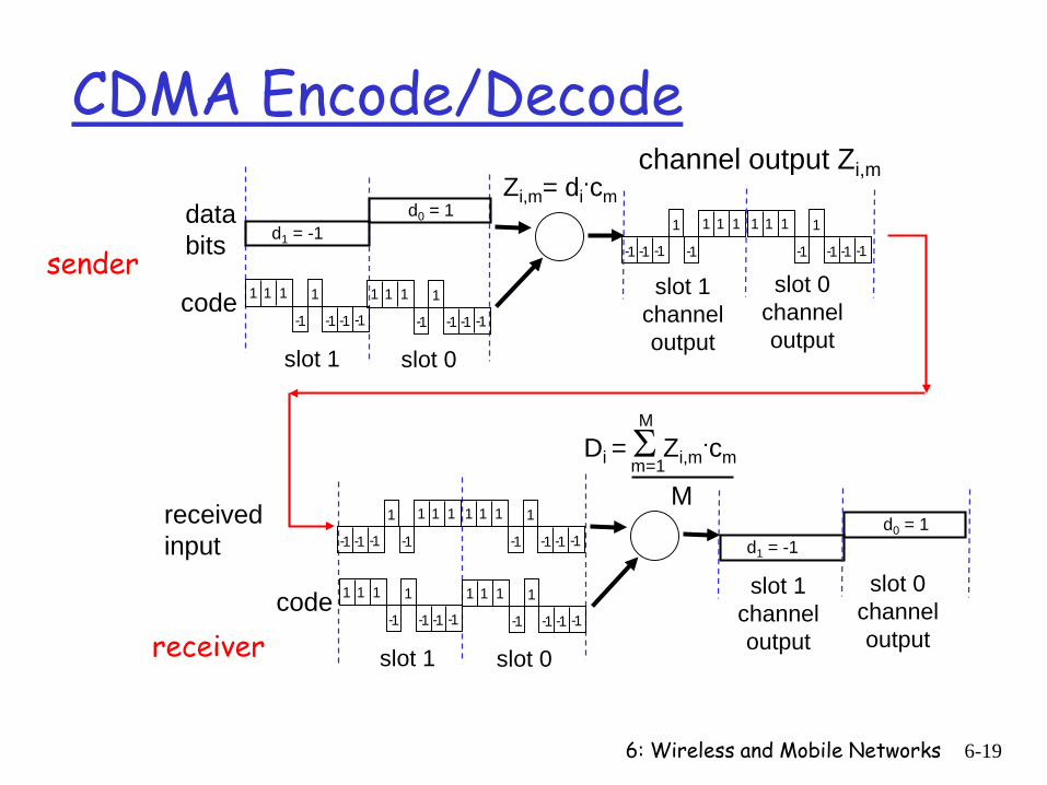
6: Wireless and Mobile Networks 6-19
CDMA Encode/Decode
slot 1 slot 0
d1 = -1
1 1 1 1
1- 1- 1- 1-
Zi,m= di.cm
d0 = 1
1 1 1 1
1- 1- 1- 1-
1 1 1 1
1- 1- 1- 1-
1 1 11
1-1- 1- 1-
slot 0channeloutput
slot 1channeloutput
channel output Zi,m
sendercode
databits
slot 1 slot 0
d1 = -1d0 = 1
1 1 1 1
1- 1- 1- 1-
1 1 1 1
1- 1- 1- 1-
1 1 1 1
1- 1- 1- 1-
1 1 11
1-1- 1- 1-
slot 0channeloutput
slot 1channeloutputreceiver
code
receivedinput
Di = Σ Zi,m.cmm=1
M
M
6: Wireless and Mobile Networks 6-20
CDMA: two-sender interference
6: Wireless and Mobile Networks 6-21
Chapter 6 outline
6.1 Introduction
Wireless 6.2 Wireless links,
characteristics CDMA
6.3 IEEE 802.11 wireless LANs (“wi-fi”)
6.4 cellular Internet access architecture standards (e.g., GSM)
Mobility 6.5 Principles:
addressing and routing to mobile users
6.6 Mobile IP 6.7 Handling mobility in
cellular networks 6.8 Mobility and higher-
layer protocols
6.9 Summary
6: Wireless and Mobile Networks 6-22
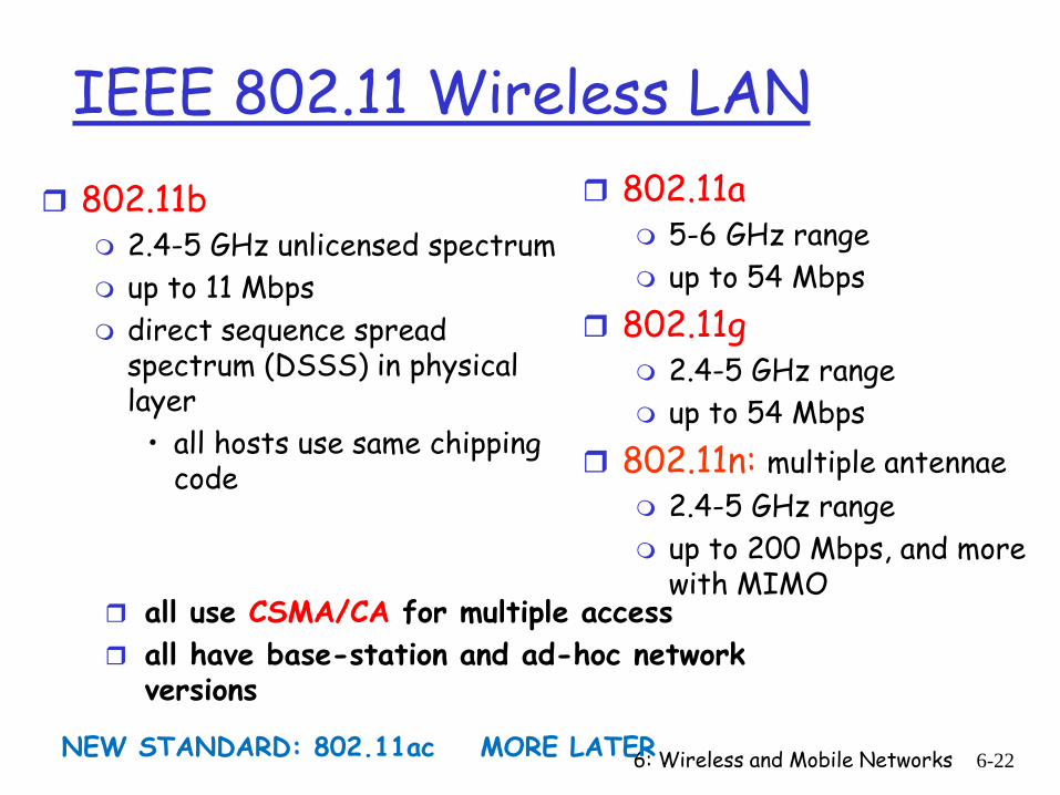
IEEE 802.11 Wireless LAN 802.11b
2.4-5 GHz unlicensed spectrum up to 11 Mbps direct sequence spread
spectrum (DSSS) in physical layer
• all hosts use same chipping code
802.11a 5-6 GHz range up to 54 Mbps
802.11g 2.4-5 GHz range up to 54 Mbps
802.11n: multiple antennae 2.4-5 GHz range up to 200 Mbps, and more
with MIMO all use CSMA/CA for multiple access all have base-station and ad-hoc network
versions
NEW STANDARD: 802.11ac MORE LATER
6: Wireless and Mobile Networks 6-23
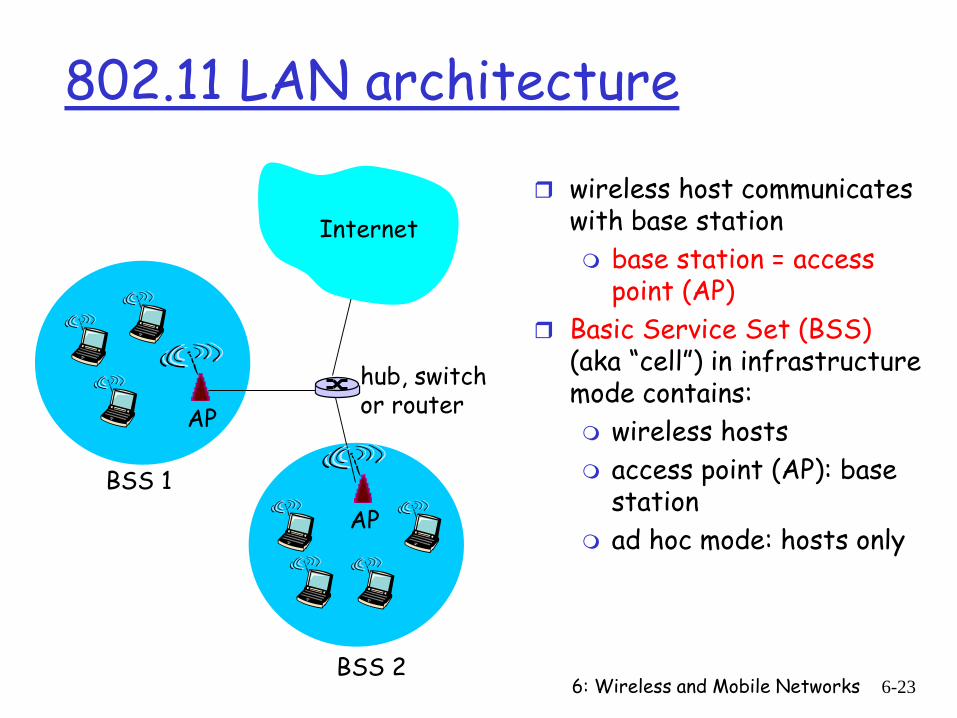
802.11 LAN architecture
wireless host communicates with base station base station = access
point (AP) Basic Service Set (BSS)
(aka “cell”) in infrastructure mode contains: wireless hosts access point (AP): base
station ad hoc mode: hosts only
BSS 1
BSS 2
Internet
hub, switchor routerAP
AP
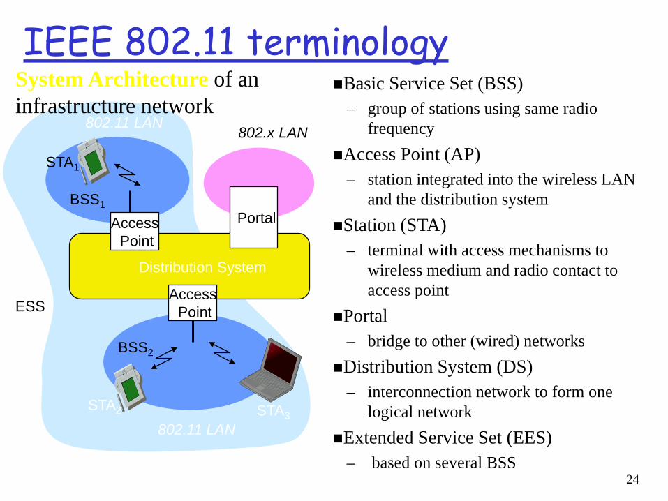
IEEE 802.11 terminologyBasic Service Set (BSS)
– group of stations using same radio frequency
Access Point (AP)– station integrated into the wireless LAN
and the distribution systemStation (STA)
– terminal with access mechanisms to wireless medium and radio contact to access point
Portal– bridge to other (wired) networks
Distribution System (DS)– interconnection network to form one
logical network Extended Service Set (EES)
– based on several BSS
Distribution System
Portal
802.x LAN
AccessPoint
802.11 LAN
BSS2
802.11 LAN
BSS1
AccessPoint
STA1
STA2 STA3
ESS
System Architecture of an infrastructure network
24
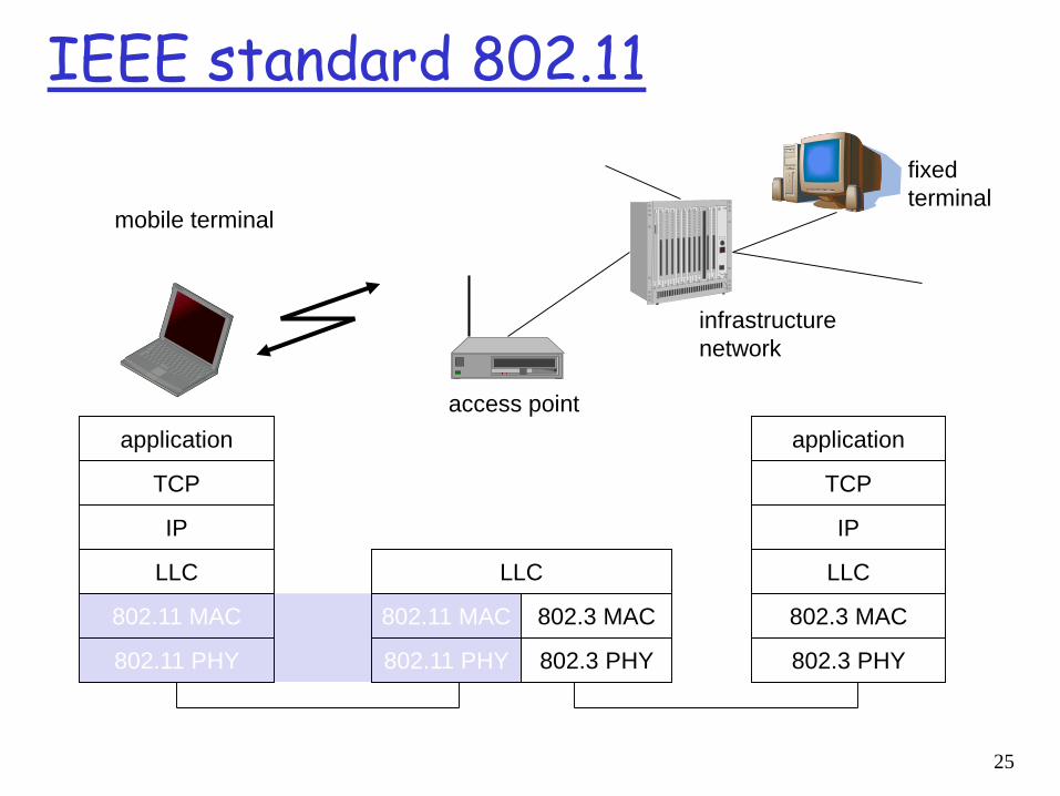
IEEE standard 802.11
mobile terminal
access point
fixedterminal
application
TCP
802.11 PHY
802.11 MAC
IP
802.3 MAC
802.3 PHY
application
TCP
802.3 PHY
802.3 MAC
IP
802.11 MAC
802.11 PHY
LLC
infrastructurenetwork
LLC LLC
25
6: Wireless and Mobile Networks 6-26
802.11: Channels, association
802.11b: 2.4GHz - 2.485GHz spectrum divided into 11 physical channels at different frequencies AP admin chooses frequency for AP interference possible: channel can be same as
that chosen by neighboring AP! host: must associate with an AP
scans channels, listening for beacon framescontaining AP’s name (SSID) and MAC address
selects AP to associate withmay perform authentication [Chapter 8] will typically run DHCP to get IP address in AP’s
subnet
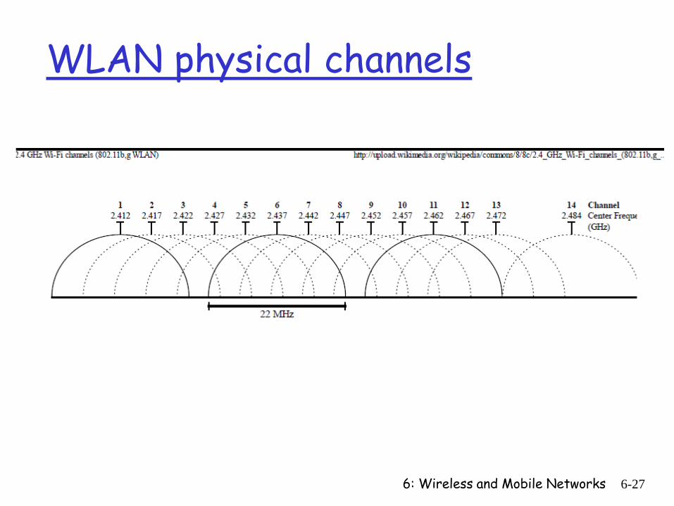
WLAN physical channels
6: Wireless and Mobile Networks 6-27
6: Wireless and Mobile Networks 6-28
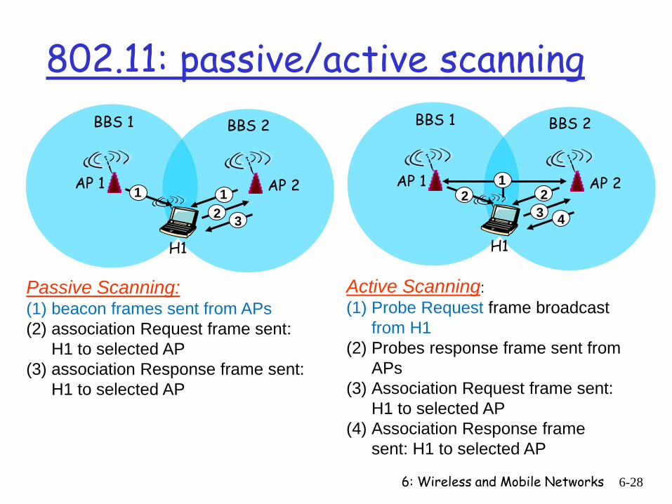
802.11: passive/active scanning
AP 2AP 1
H1
BBS 2BBS 1
122
3 4
Active Scanning: (1) Probe Request frame broadcast
from H1(2) Probes response frame sent from
APs(3) Association Request frame sent:
H1 to selected AP (4) Association Response frame
sent: H1 to selected AP
AP 2AP 1
H1
BBS 2BBS 1
12 3
1
Passive Scanning:(1) beacon frames sent from APs(2) association Request frame sent:
H1 to selected AP (3) association Response frame sent:
H1 to selected AP
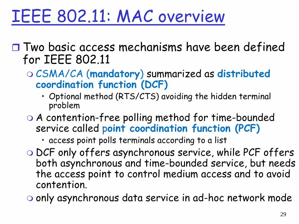
IEEE 802.11: MAC overview Two basic access mechanisms have been defined
for IEEE 802.11 CSMA/CA (mandatory) summarized as distributed
coordination function (DCF)• Optional method (RTS/CTS) avoiding the hidden terminal
problem A contention-free polling method for time-bounded
service called point coordination function (PCF)• access point polls terminals according to a list
DCF only offers asynchronous service, while PCF offers both asynchronous and time-bounded service, but needs the access point to control medium access and to avoid contention.
only asynchronous data service in ad-hoc network mode29
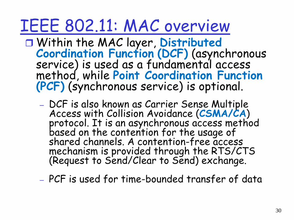
IEEE 802.11: MAC overviewWithin the MAC layer, Distributed
Coordination Function (DCF) (asynchronous service) is used as a fundamental access method, while Point Coordination Function (PCF) (synchronous service) is optional. – DCF is also known as Carrier Sense Multiple
Access with Collision Avoidance (CSMA/CA) protocol. It is an asynchronous access method based on the contention for the usage of shared channels. A contention-free access mechanism is provided through the RTS/CTS (Request to Send/Clear to Send) exchange.
– PCF is used for time-bounded transfer of data
30
6: Wireless and Mobile Networks 6-31
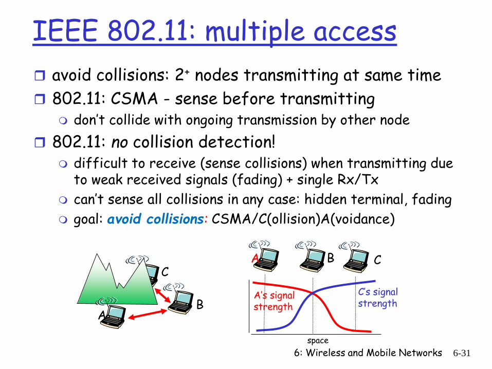
IEEE 802.11: multiple access avoid collisions: 2+ nodes transmitting at same time 802.11: CSMA - sense before transmitting
don’t collide with ongoing transmission by other node 802.11: no collision detection!
difficult to receive (sense collisions) when transmitting due to weak received signals (fading) + single Rx/Tx
can’t sense all collisions in any case: hidden terminal, fading goal: avoid collisions: CSMA/C(ollision)A(voidance)
AB
CA B C
A’s signalstrength
space
C’s signalstrength
IEEE 802.11: CSMA/CA Collision Avoidance
idea is to prevent collisions at the moment they are most likely to occur , i.e. when the bus is released (since many stations may compete then).
In the event medium is sensed busy, all clients are forced to wait for a random number of timeslots and then sense the medium again, before starting a transmission. (more later)
If the medium is sensed to be busy, the client freezes its timer until it becomes free again. (more later)
Thus, the chance of two clients starting to send simultaneously is reduced.
32
IEEE 802.11: MAC overview CSMA/CA protocol basics:
medium can be busy or idle (detected by the CCAClear Channel Assessment-CCA signal of the physical layer)
• If medium busy this can be due to data frames or other control frames
during a contention phase several nodes try to access medium
optionally, the standard allows for collision free operation through small reservation packets (RTS, CTS)
33
6: Wireless and Mobile Networks 6-34
Avoiding collisionsidea: allow sender to “reserve” channel rather than random
access of data frames: avoid collisions of long data frames sender first transmits small request-to-send (RTS)
packets to BS using CSMA RTSs may still collide with each other (but they’re short)
BS broadcasts clear-to-send CTS in response to RTS RTS heard by all nodes
sender transmits data frame other stations defer transmissions
avoid data frame collisions completely using small reservation packets!
6: Wireless and Mobile Networks 6-35
IEEE 802.11 MAC Protocol: CSMA/CA
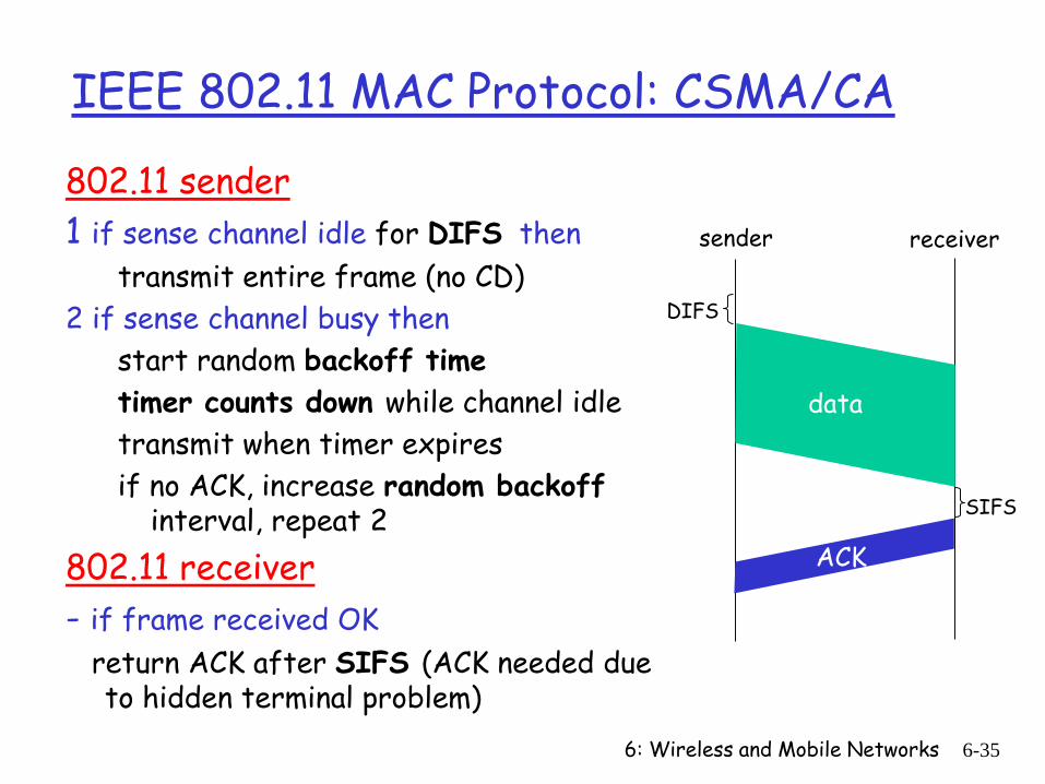
802.11 sender1 if sense channel idle for DIFS then
transmit entire frame (no CD)2 if sense channel busy then
start random backoff timetimer counts down while channel idletransmit when timer expiresif no ACK, increase random backoff
interval, repeat 2802.11 receiver- if frame received OK
return ACK after SIFS (ACK needed due to hidden terminal problem)
sender receiver
DIFS
data
SIFS
ACK
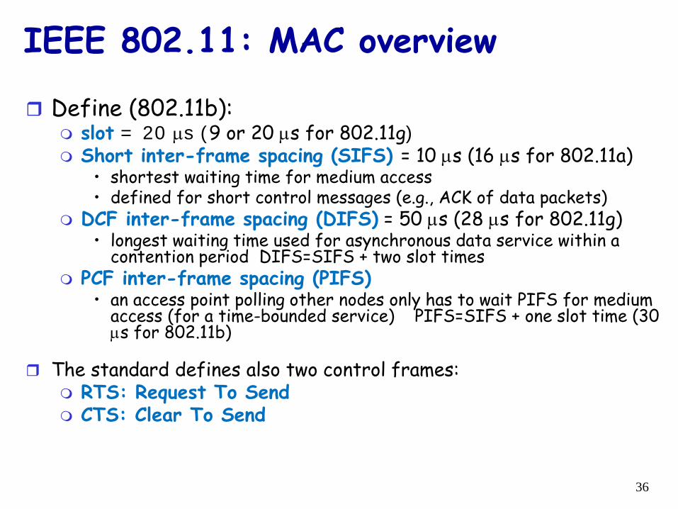
Define (802.11b): slot = 20 µs (9 or 20 µs for 802.11g) Short inter-frame spacing (SIFS) = 10 µs (16 µs for 802.11a)
• shortest waiting time for medium access• defined for short control messages (e.g., ACK of data packets)
DCF inter-frame spacing (DIFS) = 50 µs (28 µs for 802.11g)• longest waiting time used for asynchronous data service within a
contention period DIFS=SIFS + two slot times PCF inter-frame spacing (PIFS)
• an access point polling other nodes only has to wait PIFS for medium access (for a time-bounded service) PIFS=SIFS + one slot time (30 µs for 802.11b)
The standard defines also two control frames: RTS: Request To Send CTS: Clear To Send
IEEE 802.11: MAC overview
36
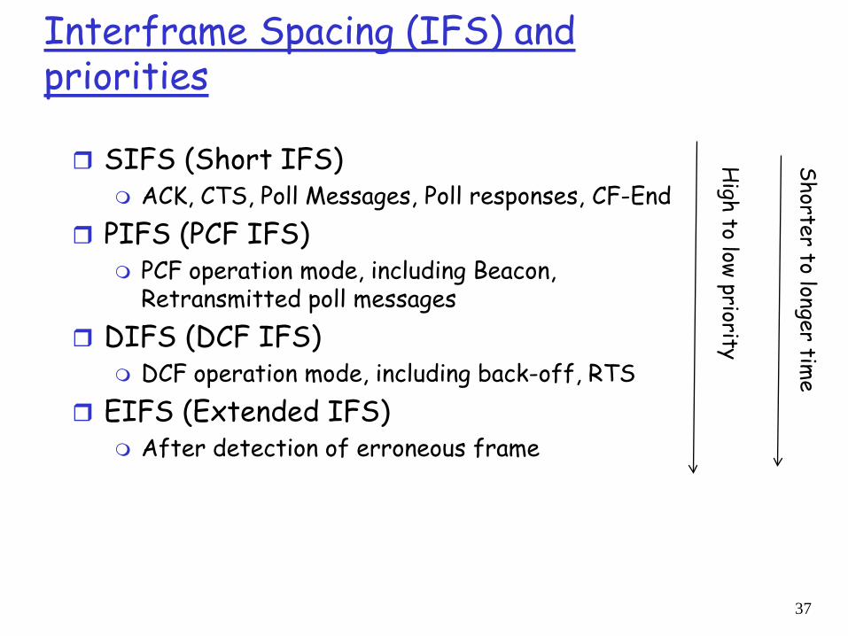
Interframe Spacing (IFS) and priorities
SIFS (Short IFS) ACK, CTS, Poll Messages, Poll responses, CF-End
PIFS (PCF IFS) PCF operation mode, including Beacon,
Retransmitted poll messages DIFS (DCF IFS)
DCF operation mode, including back-off, RTS EIFS (Extended IFS)
After detection of erroneous frame
High to low priority
Shorter to longer time
37
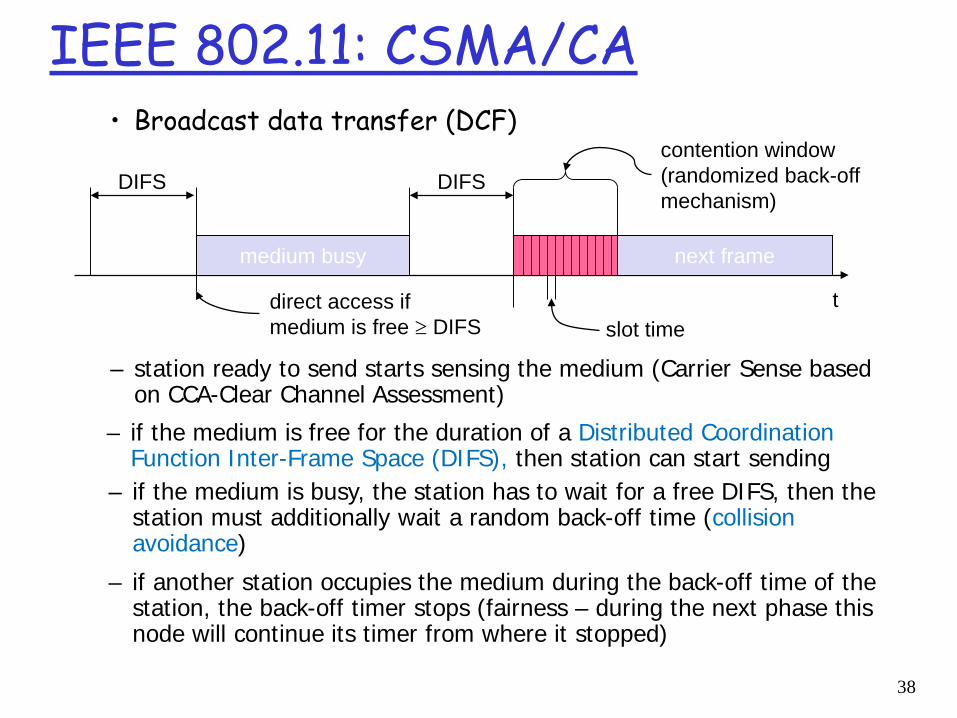
IEEE 802.11: CSMA/CA • Broadcast data transfer (DCF)
t
medium busy
DIFSDIFS
next frame
contention window(randomized back-offmechanism)
slot timedirect access if medium is free ≥ DIFS
– station ready to send starts sensing the medium (Carrier Sense based on CCA-Clear Channel Assessment)
– if the medium is busy, the station has to wait for a free DIFS, then the station must additionally wait a random back-off time (collision avoidance)
– if another station occupies the medium during the back-off time of the station, the back-off timer stops (fairness – during the next phase this node will continue its timer from where it stopped)
– if the medium is free for the duration of a Distributed Coordination Function Inter-Frame Space (DIFS), then station can start sending
38
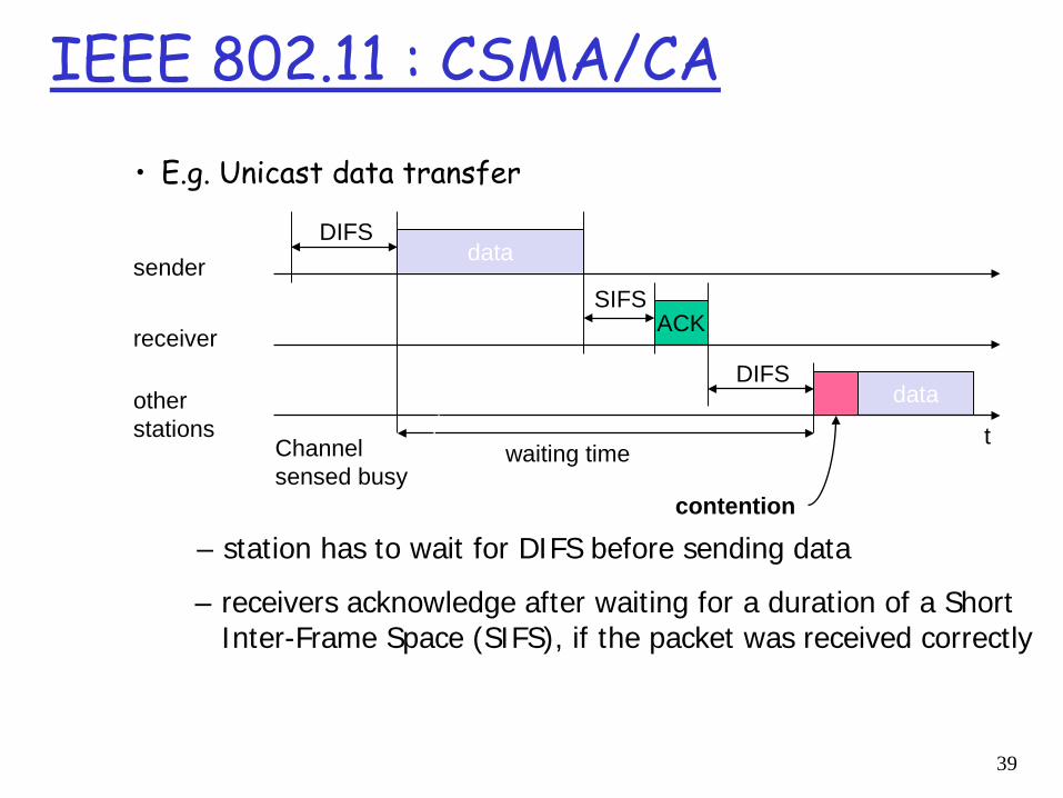
IEEE 802.11 : CSMA/CA • E.g. Unicast data transfer
DIFS
data
ACK
otherstations
receiver
sender
t
data
DIFS
waiting time
contention
SIFS
– station has to wait for DIFS before sending data
– receivers acknowledge after waiting for a duration of a Short Inter-Frame Space (SIFS), if the packet was received correctly
Channel sensed busy
39
EE802.11: Exponential backoff mechanism
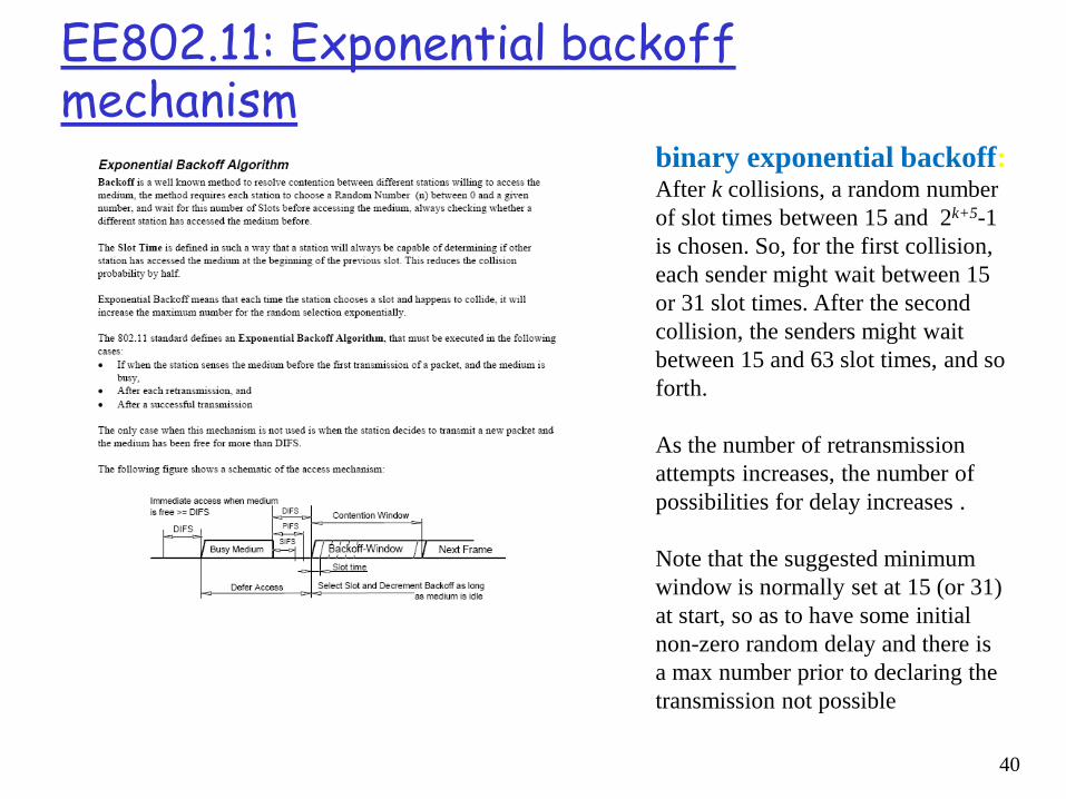
binary exponential backoff: After k collisions, a random number of slot times between 15 and 2k+5-1 is chosen. So, for the first collision, each sender might wait between 15 or 31 slot times. After the second collision, the senders might wait between 15 and 63 slot times, and so forth.
As the number of retransmission attempts increases, the number of possibilities for delay increases .
Note that the suggested minimum window is normally set at 15 (or 31) at start, so as to have some initial non-zero random delay and there is a max number prior to declaring the transmission not possible
40
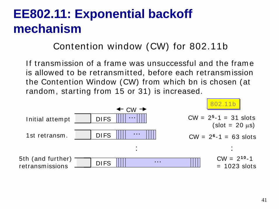
Contention window (CW) for 802.11b
If transmission of a frame was unsuccessful and the frame is allowed to be retransmitted, before each retransmission the Contention Window (CW) from which bn is chosen (at random, starting from 15 or 31) is increased.
DIFS … CW = 25-1 = 31 slots(slot = 20 µs)
Initial attempt
DIFS …CW = 26-1 = 63 slots1st retransm.
DIFSCW = 210-1 = 1023 slots
5th (and further) retransmissions
:…
CW802.11b
EE802.11: Exponential backoff mechanism
:
41
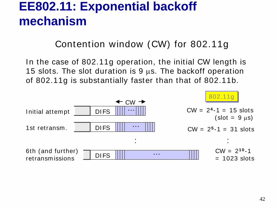
Contention window (CW) for 802.11g
In the case of 802.11g operation, the initial CW length is 15 slots. The slot duration is 9 µs. The backoff operation of 802.11g is substantially faster than that of 802.11b.
DIFS … CW = 24-1 = 15 slots(slot = 9 µs)
Initial attempt
DIFS …CW = 25-1 = 31 slots1st retransm.
DIFSCW = 210-1 = 1023 slots
6th (and further) retransmissions
:…
CW802.11g
EE802.11: Exponential backoff mechanism
:
42
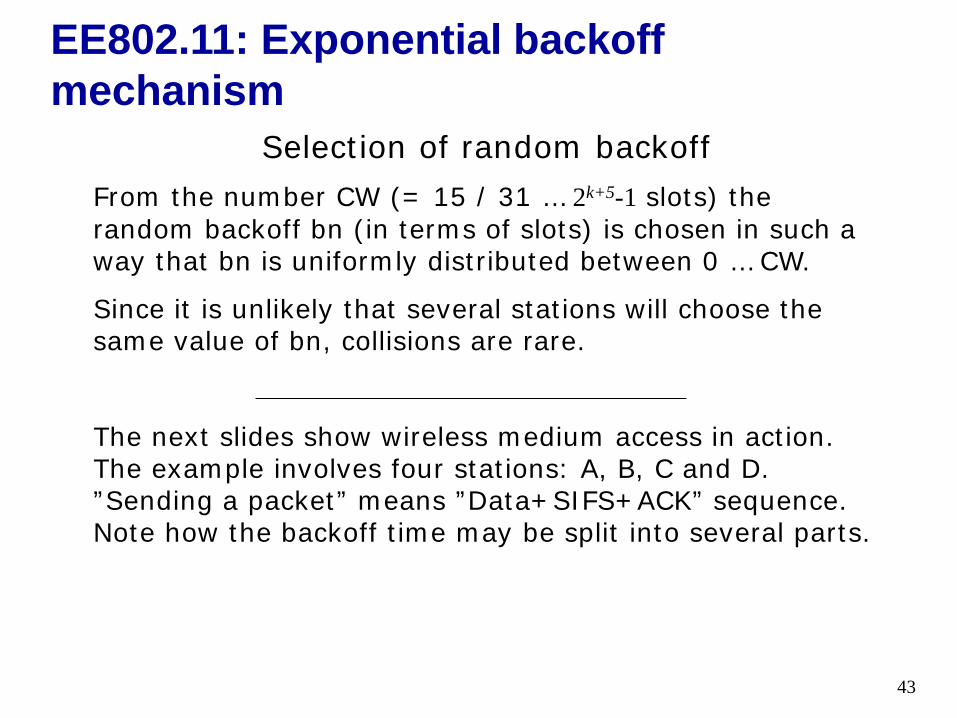
Selection of random backoffFrom the number CW (= 15 / 31 … 2k+5-1 slots) the random backoff bn (in terms of slots) is chosen in such a way that bn is uniformly distributed between 0 … CW.
Since it is unlikely that several stations will choose the same value of bn, collisions are rare.
The next slides show wireless medium access in action. The example involves four stations: A, B, C and D. ”Sending a packet” means ”Data+SIFS+ACK” sequence. Note how the backoff time may be split into several parts.
EE802.11: Exponential backoff mechanism
43
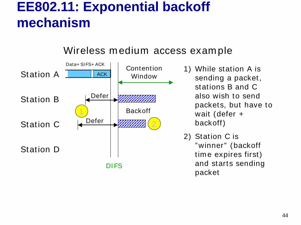
Wireless medium access example
Station A
Station B
Station C
Station D
DIFS
Defer
Defer
Contention Window
Backoff
1) While station A is sending a packet, stations B and C also wish to send packets, but have to wait (defer + backoff)
2) Station C is ”winner” (backoff time expires first) and starts sending packet
21
ACK
Data+SIFS+ACK
EE802.11: Exponential backoff mechanism
44
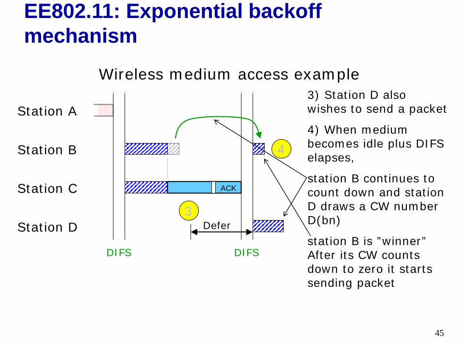
Wireless medium access example
Station A
Station B
Station C
Station D
DIFS DIFS
Defer
3) Station D also wishes to send a packet
4) When medium becomes idle plus DIFS elapses,
station B continues to count down and station D draws a CW number D(bn)
station B is ”winner” After its CW counts down to zero it starts sending packet
3
4
ACK
EE802.11: Exponential backoff mechanism
45
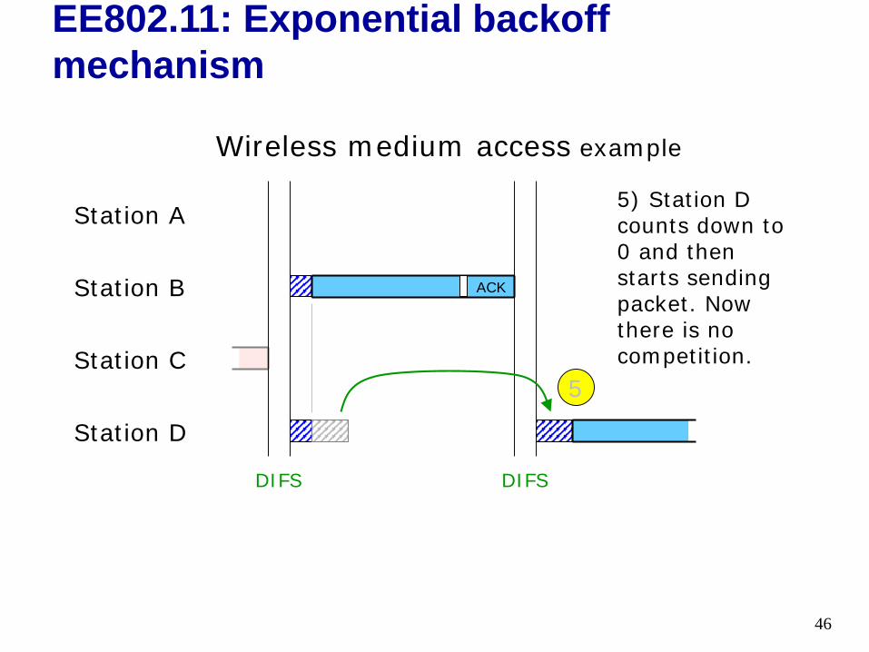
Wireless medium access example
Station A
Station B
Station C
Station D
DIFS
5) Station D counts down to 0 and then starts sending packet. Now there is no competition.
DIFS
5
ACK
EE802.11: Exponential backoff mechanism
46
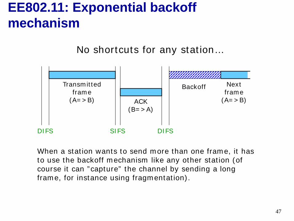
No shortcuts for any station…
DIFS SIFS DIFS
ACK (B=>A)
Transmitted frame
(A=>B)
Next frame
(A=>B)
Backoff
When a station wants to send more than one frame, it has to use the backoff mechanism like any other station (of course it can ”capture” the channel by sending a long frame, for instance using fragmentation).
EE802.11: Exponential backoff mechanism
47
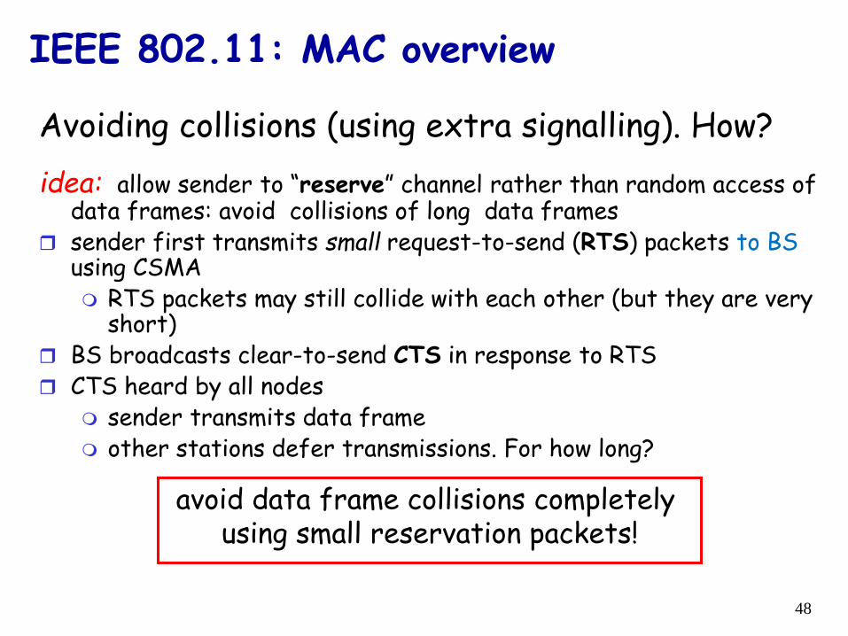
Avoiding collisions (using extra signalling). How?idea: allow sender to “reserve” channel rather than random access of
data frames: avoid collisions of long data frames sender first transmits small request-to-send (RTS) packets to BS
using CSMA RTS packets may still collide with each other (but they are very
short) BS broadcasts clear-to-send CTS in response to RTS CTS heard by all nodes
sender transmits data frame other stations defer transmissions. For how long?
avoid data frame collisions completely using small reservation packets!
IEEE 802.11: MAC overview
48
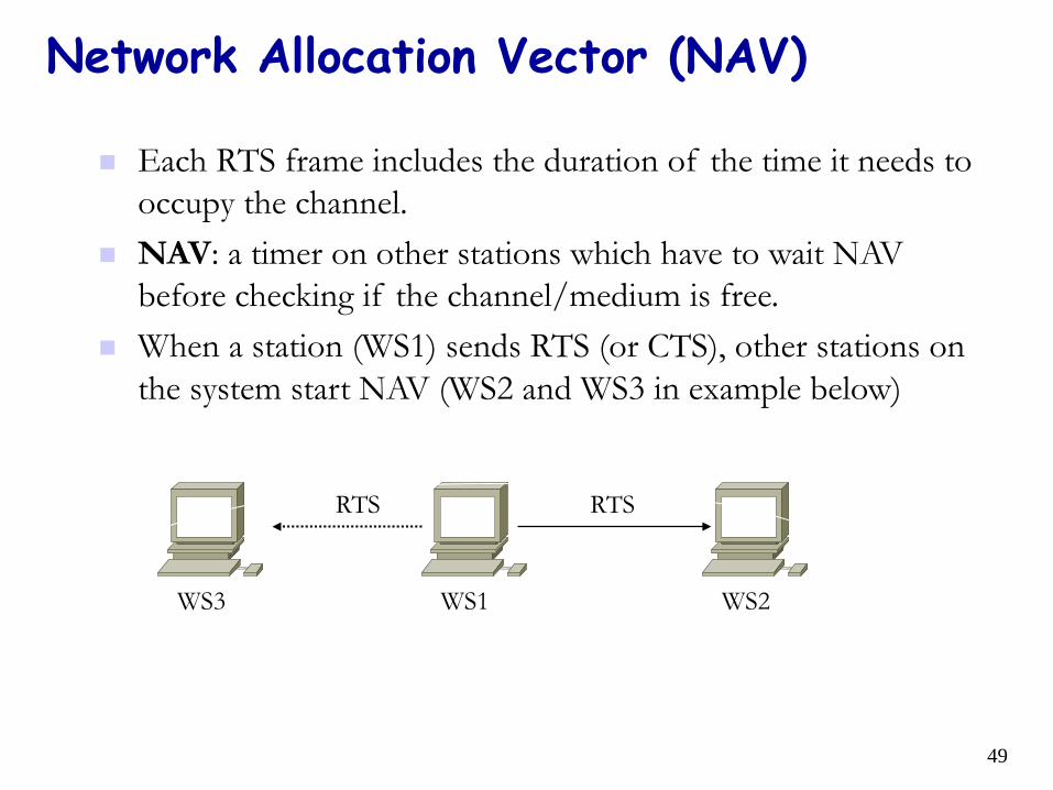
Network Allocation Vector (NAV)
Each RTS frame includes the duration of the time it needs to occupy the channel.
NAV: a timer on other stations which have to wait NAV before checking if the channel/medium is free.
When a station (WS1) sends RTS (or CTS), other stations on the system start NAV (WS2 and WS3 in example below)
RTSRTS
WS3 WS1 WS2
49
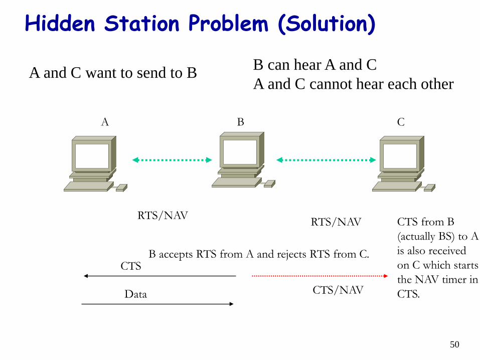
Hidden Station Problem (Solution)
B CA
RTS/NAV RTS/NAV
CTS
Data CTS/NAV
B accepts RTS from A and rejects RTS from C.
CTS from B (actually BS) to A is also received on C which starts the NAV timer in CTS.
A and C want to send to B B can hear A and CA and C cannot hear each other
50
Busy Medium
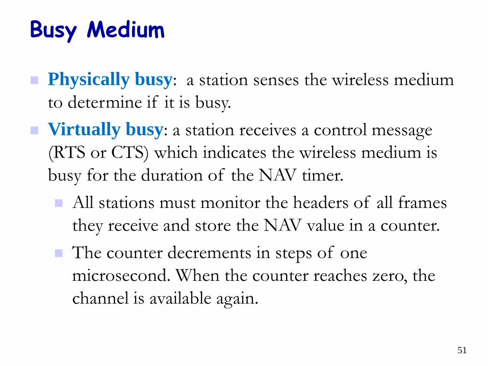
Physically busy: a station senses the wireless medium to determine if it is busy.
Virtually busy: a station receives a control message (RTS or CTS) which indicates the wireless medium is busy for the duration of the NAV timer. All stations must monitor the headers of all frames
they receive and store the NAV value in a counter. The counter decrements in steps of one
microsecond. When the counter reaches zero, the channel is available again.
51
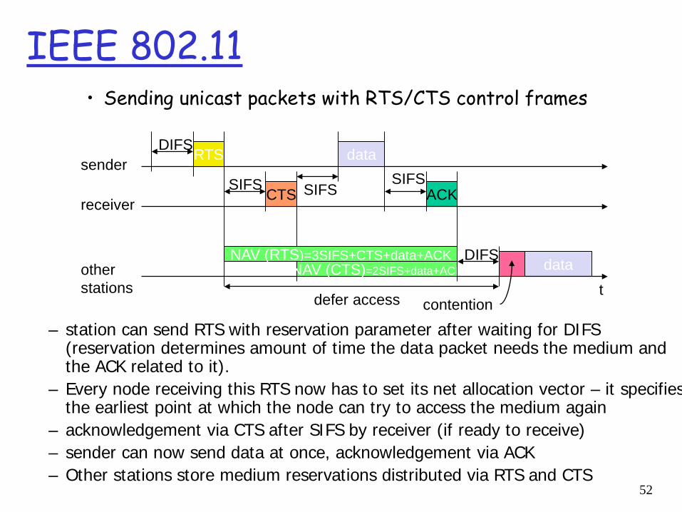
IEEE 802.11 • Sending unicast packets with RTS/CTS control frames
SIFS
DIFS
data
ACK
totherstations
receiver
sender data
DIFS
defer access contention
RTS
CTSSIFS SIFS
NAV (RTS)=3SIFS+CTS+data+ACKNAV (CTS)=2SIFS+data+ACK
– station can send RTS with reservation parameter after waiting for DIFS (reservation determines amount of time the data packet needs the medium and the ACK related to it).
– Every node receiving this RTS now has to set its net allocation vector – it specifies the earliest point at which the node can try to access the medium again
– acknowledgement via CTS after SIFS by receiver (if ready to receive)– sender can now send data at once, acknowledgement via ACK– Other stations store medium reservations distributed via RTS and CTS
52
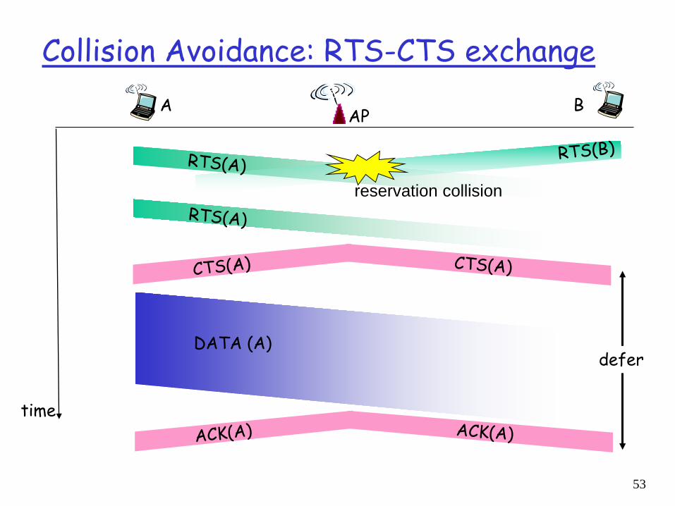
Collision Avoidance: RTS-CTS exchange
APA B
time
DATA (A)
reservation collision
defer
53
6: Wireless and Mobile Networks 6-54
framecontrol duration address
1address
2address
4address
3 payload CRC
2 2 6 6 6 2 6 0 - 2312 4seq
control
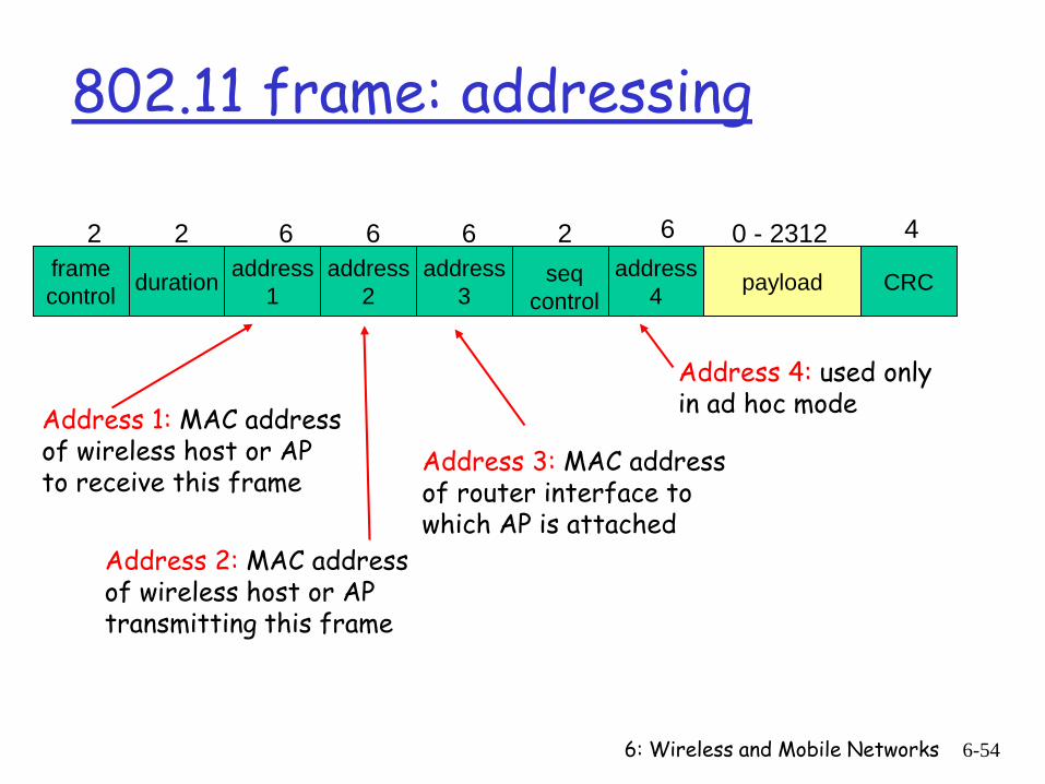
802.11 frame: addressing
Address 2: MAC addressof wireless host or AP transmitting this frame
Address 1: MAC addressof wireless host or AP to receive this frame
Address 3: MAC addressof router interface to which AP is attached
Address 4: used only in ad hoc mode
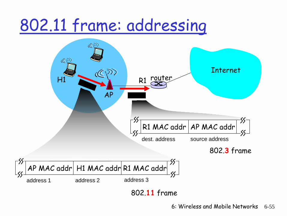
6: Wireless and Mobile Networks 6-55
Internetrouter
AP
H1 R1
AP MAC addr H1 MAC addr R1 MAC addraddress 1 address 2 address 3
802.11 frame
R1 MAC addr AP MAC addr dest. address source address
802.3 frame
802.11 frame: addressing
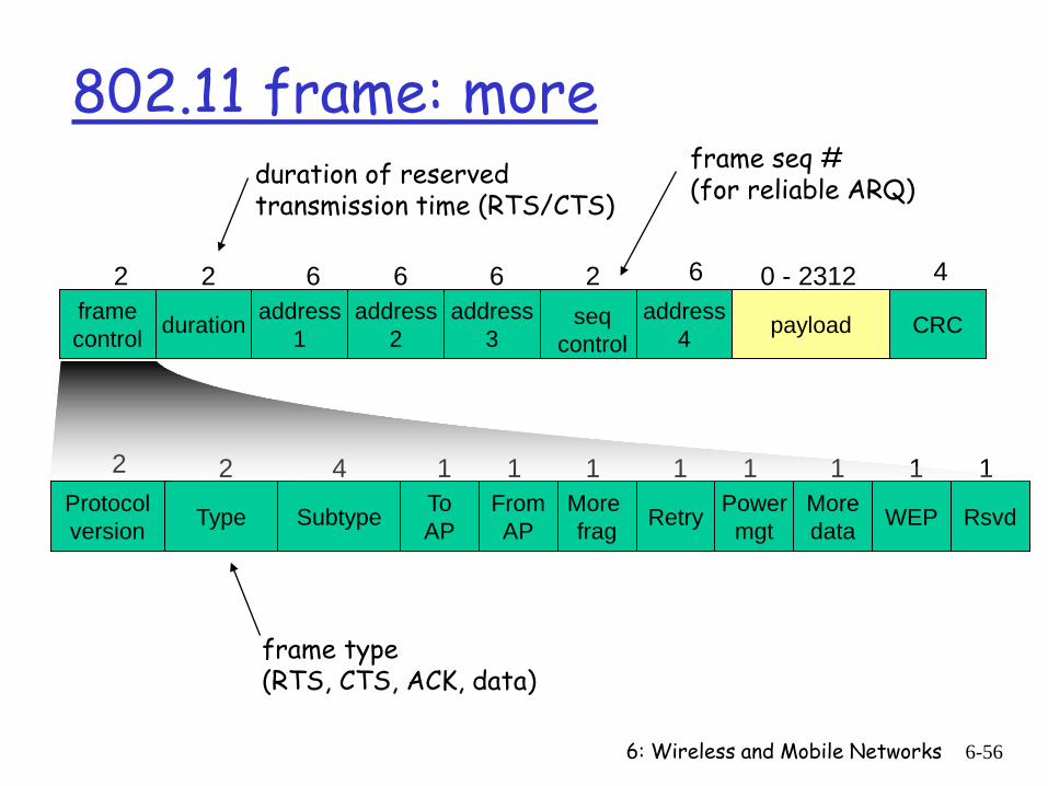
6: Wireless and Mobile Networks 6-56
framecontrol duration address
1address
2address
4address
3 payload CRC
2 2 6 6 6 2 6 0 - 2312 4seq
control
Type FromAPSubtype To
APMore frag WEPMore
dataPower
mgtRetry RsvdProtocolversion
2 2 4 1 1 1 1 1 11 1
802.11 frame: moreduration of reserved transmission time (RTS/CTS)
frame seq #(for reliable ARQ)
frame type(RTS, CTS, ACK, data)
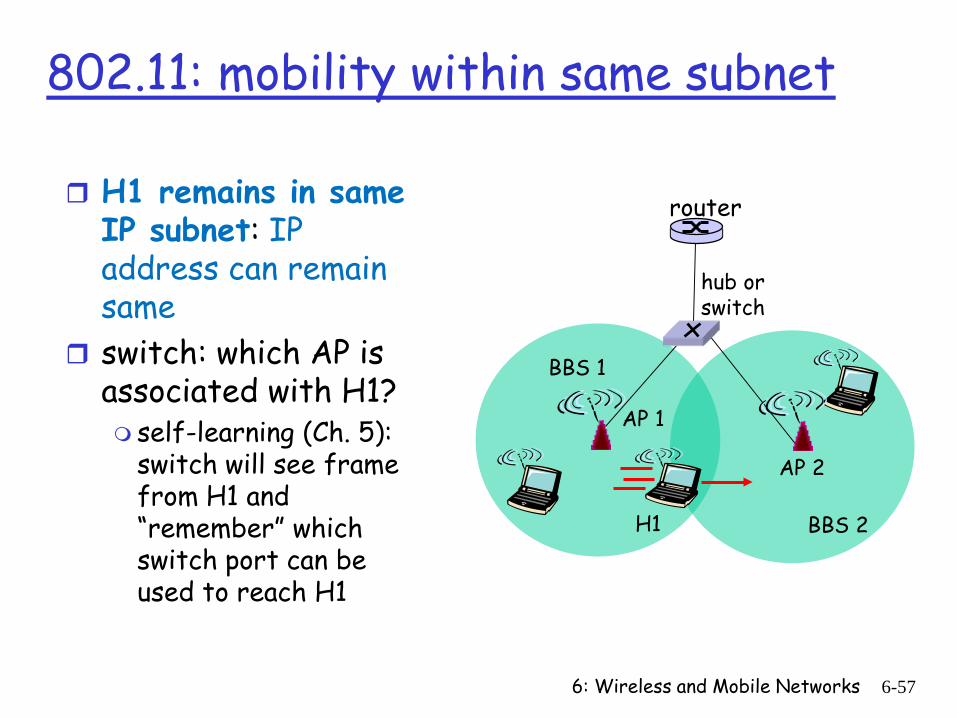
6: Wireless and Mobile Networks 6-57
hub or switch
AP 2
AP 1
H1 BBS 2
BBS 1
802.11: mobility within same subnet
router H1 remains in same IP subnet: IP address can remain same
switch: which AP is associated with H1? self-learning (Ch. 5):
switch will see frame from H1 and “remember” which switch port can be used to reach H1
6: Wireless and Mobile Networks 6-58
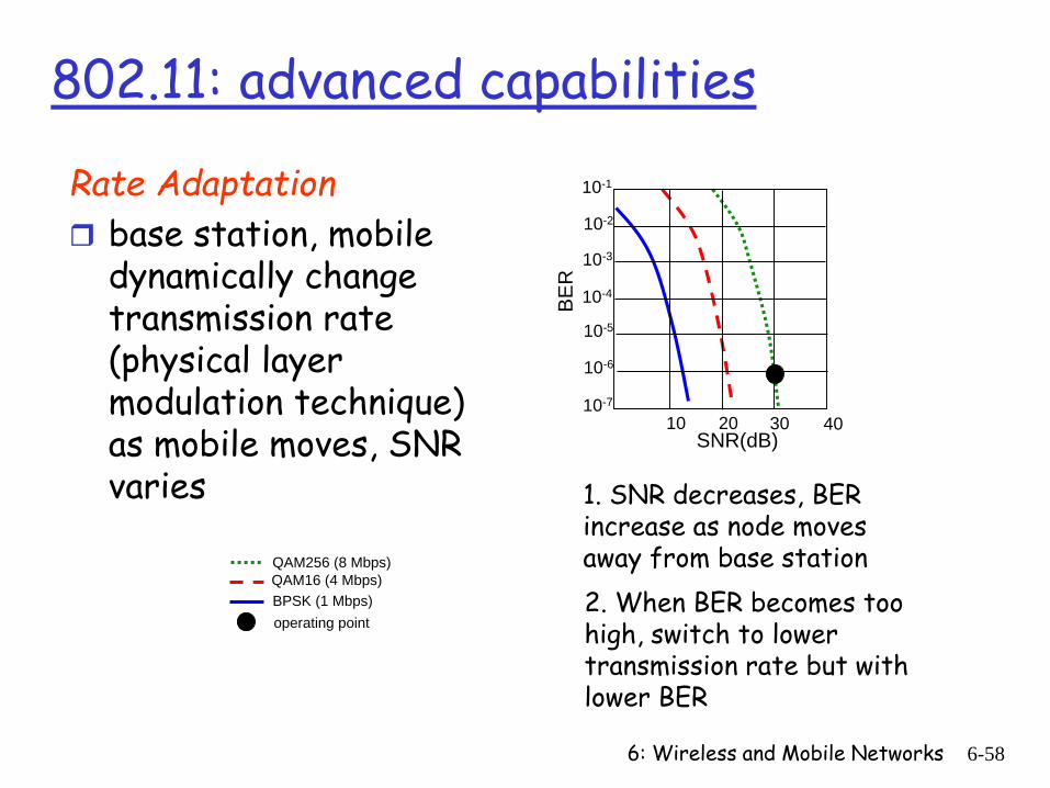
802.11: advanced capabilities
Rate Adaptation base station, mobile
dynamically change transmission rate (physical layer modulation technique) as mobile moves, SNR varies
QAM256 (8 Mbps)QAM16 (4 Mbps)BPSK (1 Mbps)
10 20 30 40SNR(dB)
BER
10-1
10-2
10-3
10-5
10-6
10-7
10-4
operating point
1. SNR decreases, BER increase as node moves away from base station2. When BER becomes too high, switch to lower transmission rate but with lower BER
6: Wireless and Mobile Networks 6-59
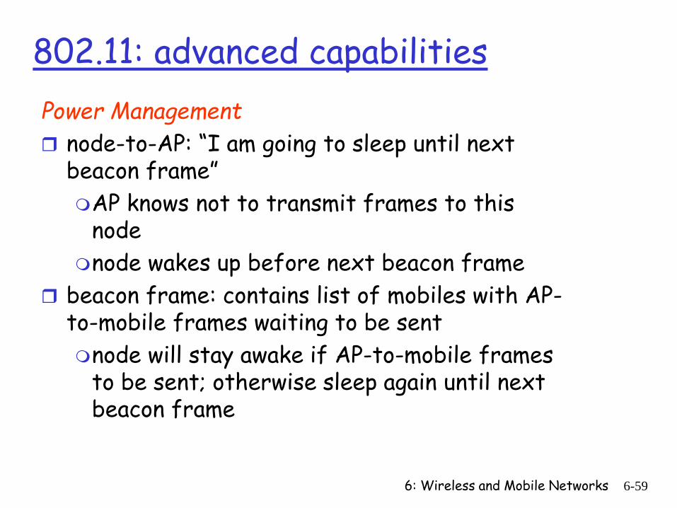
802.11: advanced capabilitiesPower Management node-to-AP: “I am going to sleep until next
beacon frame”AP knows not to transmit frames to this
nodenode wakes up before next beacon frame
beacon frame: contains list of mobiles with AP-to-mobile frames waiting to be sentnode will stay awake if AP-to-mobile frames
to be sent; otherwise sleep again until next beacon frame
6: Wireless and Mobile Networks 6-60
M radius ofcoverage
S
SS
P
P
P
P
M
S
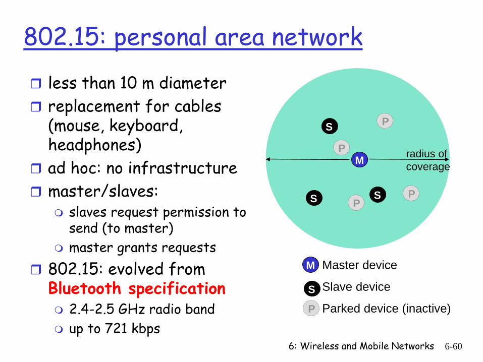
Master device
Slave device
Parked device (inactive)P
802.15: personal area network
less than 10 m diameter replacement for cables
(mouse, keyboard, headphones)
ad hoc: no infrastructure master/slaves:
slaves request permission to send (to master)
master grants requests 802.15: evolved from
Bluetooth specification 2.4-2.5 GHz radio band up to 721 kbps
6: Wireless and Mobile Networks 6-61
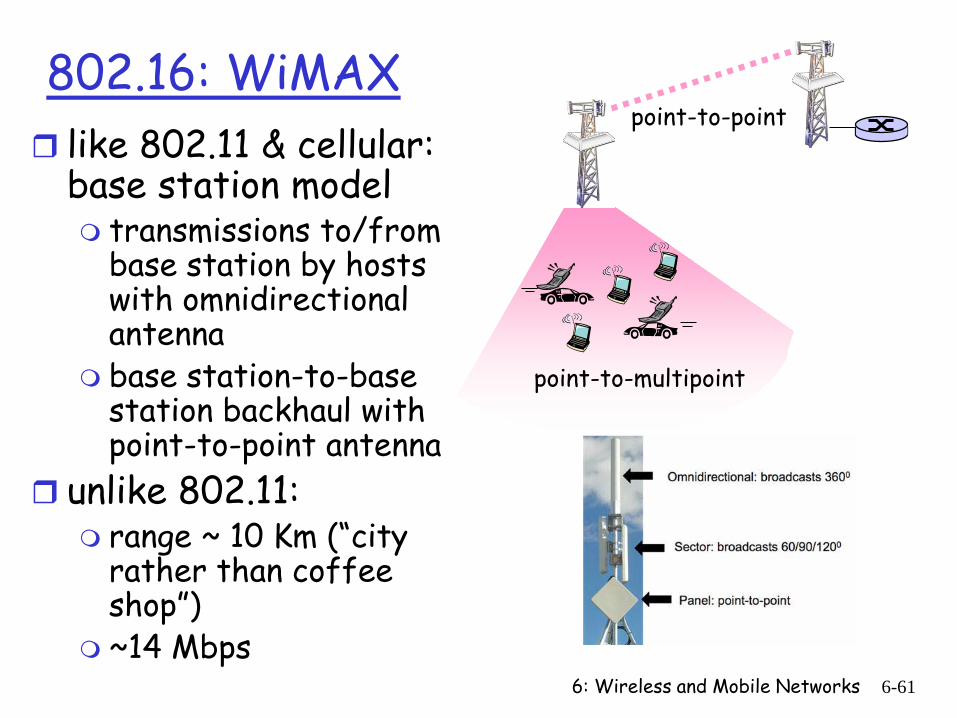
802.16: WiMAX like 802.11 & cellular:
base station model transmissions to/from
base station by hosts with omnidirectional antenna
base station-to-base station backhaul with point-to-point antenna
unlike 802.11: range ~ 10 Km (“city
rather than coffee shop”)
~14 Mbps
point-to-multipoint
point-to-point
6: Wireless and Mobile Networks 6-62
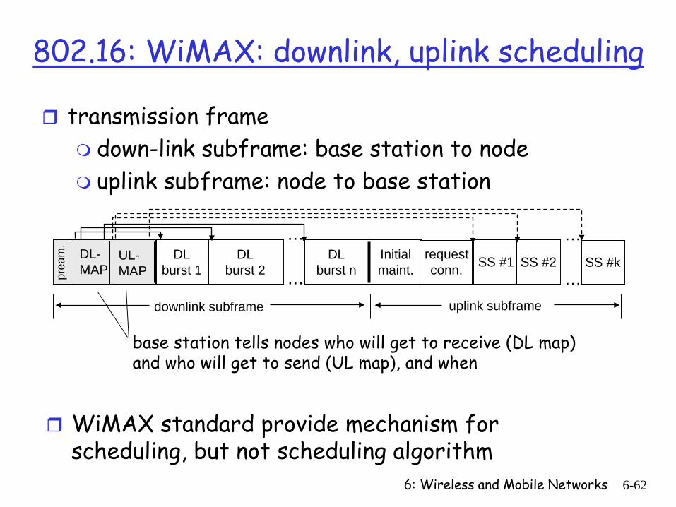
802.16: WiMAX: downlink, uplink scheduling
transmission frame down-link subframe: base station to node uplink subframe: node to base station
prea
m.
DL-MAP
UL-MAP
DLburst 1 SS #1DL
burst 2DL
burst nInitialmaint.
requestconn.
downlink subframe
SS #2 SS #k
uplink subframe
…
…
…
…
base station tells nodes who will get to receive (DL map) and who will get to send (UL map), and when
WiMAX standard provide mechanism for scheduling, but not scheduling algorithm
6: Wireless and Mobile Networks 6-63
Chapter 6 outline
6.1 Introduction
Wireless 6.2 Wireless links,
characteristics CDMA
6.3 IEEE 802.11 wireless LANs (“wi-fi”)
6.4 Cellular Internet Access architecture standards (e.g., GSM)
Mobility 6.5 Principles:
addressing and routing to mobile users
6.6 Mobile IP 6.7 Handling mobility in
cellular networks 6.8 Mobility and higher-
layer protocols
6.9 Summary
6: Wireless and Mobile Networks 6-64
Mobile Switching
Center
Public telephonenetwork, andInternet
Mobile Switching
Center
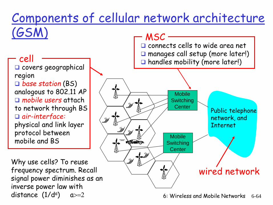
Components of cellular network architecture (GSM)
connects cells to wide area net manages call setup (more later!) handles mobility (more later!)
MSC
covers geographical region base station (BS) analogous to 802.11 AP mobile users attach to network through BS air-interface:physical and link layer protocol between mobile and BS
cell
wired networkWhy use cells? To reuse frequency spectrum. Recall signal power diminishes as an inverse power law with distance (1/dα) a>=2
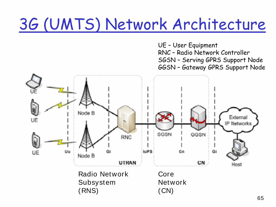
3G (UMTS) Network Architecture
Radio Network Subsystem (RNS)
Core Network (CN)
UE – User EquipmentRNC – Radio Network ControllerSGSN – Serving GPRS Support NodeGGSN – Gateway GPRS Support Node
65
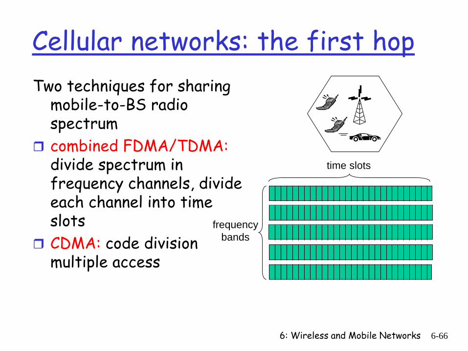
6: Wireless and Mobile Networks 6-66
Cellular networks: the first hopTwo techniques for sharing
mobile-to-BS radio spectrum
combined FDMA/TDMA:divide spectrum in frequency channels, divide each channel into time slots
CDMA: code division multiple access
frequencybands
time slots
6: Wireless and Mobile Networks 6-67
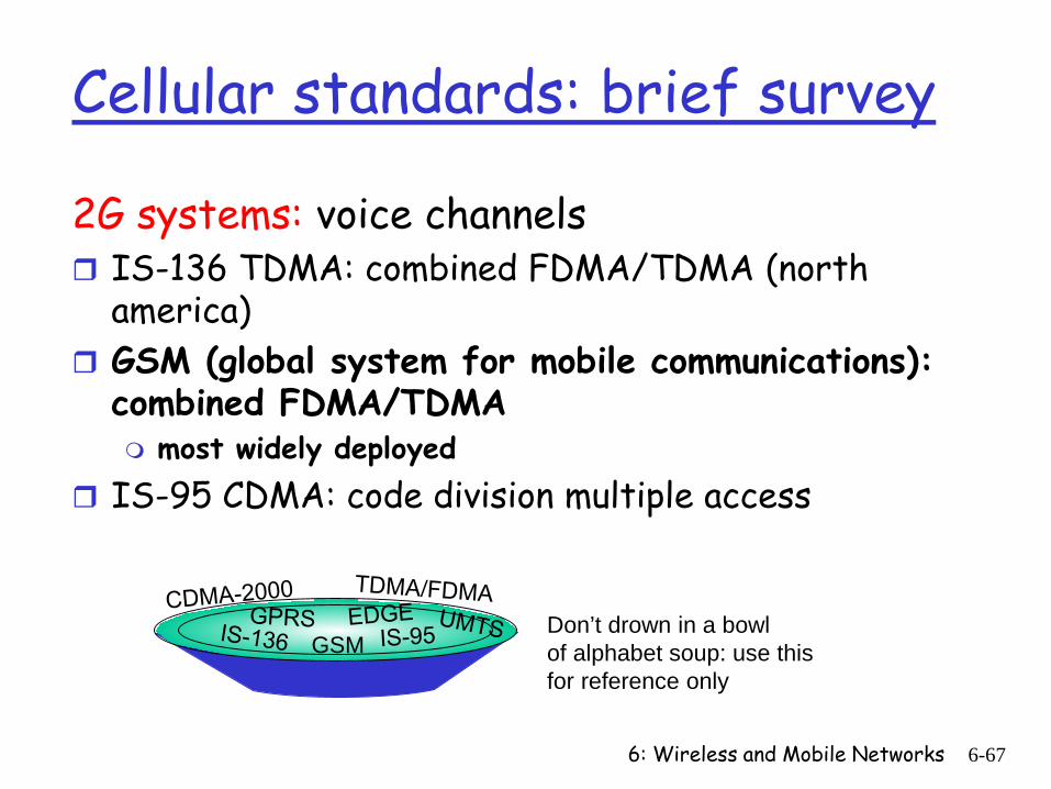
Cellular standards: brief survey
2G systems: voice channels IS-136 TDMA: combined FDMA/TDMA (north
america) GSM (global system for mobile communications):
combined FDMA/TDMA most widely deployed
IS-95 CDMA: code division multiple access
GSMDon’t drown in a bowlof alphabet soup: use thisfor reference only
6: Wireless and Mobile Networks 6-68
Cellular standards: brief survey
2.5 G systems: voice and data channels for those who can’t wait for 3G service: 2G extensions general packet radio service (GPRS)
evolved from GSM data sent on multiple channels (if available)
enhanced data rates for global evolution (EDGE) also evolved from GSM, using enhanced modulation data rates up to 384K
CDMA-2000 (phase 1) data rates up to 144K evolved from IS-95
6: Wireless and Mobile Networks 6-69
Cellular standards: brief survey3G systems: voice/data Universal Mobile Telecommunications Service (UMTS)
data service: High Speed Uplink/Downlink packet Access (HSDPA/HSUPA): 3 Mbps
CDMA-2000: CDMA in TDMA slots data service: 1xEvlution Data Optimized (1xEVDO)
up to 14 Mbps
4G LTE, LTE enhanced, …
IMT and IMT-Advanced Technologies
LTE, LTE Advanced and Wireless MAN-Advanced, are designed to enable high speed Internet/Broadband at anytime, anywhere, with higher level of user-level customization.
As per ITU for IMT-Advanced technologies, the targeted peak data rates are up to 100 Mbit/s for high mobility and up to 1 Gbit/s for low mobility scenario. Scalable bandwidths up to at least 40 MHz should be provided
key technologies: Orthogonal Frequency Division Multiplex (OFDMA) Multiple Input Multiple Output (MIMO) and System Architecture Evolution (SAE)
70
MIMO Multiple Input Multiple Output
• Uses multiple transmitter and receiver antennas, whichallow independent channels to be created in space.
• Various Approaches for MIMO: Space diversity:- to improve the communication reliability by
decreasing the sensitivity to fading by picking up multiple copiesof the same signal at different locations in space.
Beamforming:- antenna elements are used to adjust the strengthof the transmitted and received signals, based on their direction forfocusing of energy.
Spatial Multiplexing:- Increased capacity, reliability, coverage,reduction in power requirement by introducing additional spatialchannels that are exploited by using space-time coding
71
OFDMA Orthogonal Frequency Division Multiple Access
Based on the idea of dividing a given high-bit-ratedata stream into several parallel lower bit-ratestreams and modulating each stream on separatecarrier – often called sub-carriers or tones. Multi-carrier modulation scheme minimize inter-symbol
interference (ISI) by making the symbol time large enough so thatthe channel-induced delays are an insignificant (<10%) fraction ofthe symbol duration.
OFDM is a spectrally efficient version of multi-carrier modulationwhere sub-carriers are selected such that they are all orthogonal toone another over the symbol duration, thereby avoiding the need tohave non overlapping sub-carrier channels to eliminate inter-carrier interference .
72
OFDMA Orthogonal Frequency Division Multiple Access
• OFDMA can be used as a multi-access scheme, where theavailable sub-carriers may be divided into several groupsof sub-carriers called sub-channels. Different sub channelsmay be allocated to different users as a multiple accessmechanism. This type of multi access scheme is calledOFDMA.
• OFDMA is essentially a hybrid of FDMA and TDMA.Users are dynamically assigned sub-carriers (FDMA) indifferent time slots (TDMA).
• OFDMA is a flexible multiple access technique that canaccommodate many users with widely varyingapplications, data rates and QoS requirements.
73
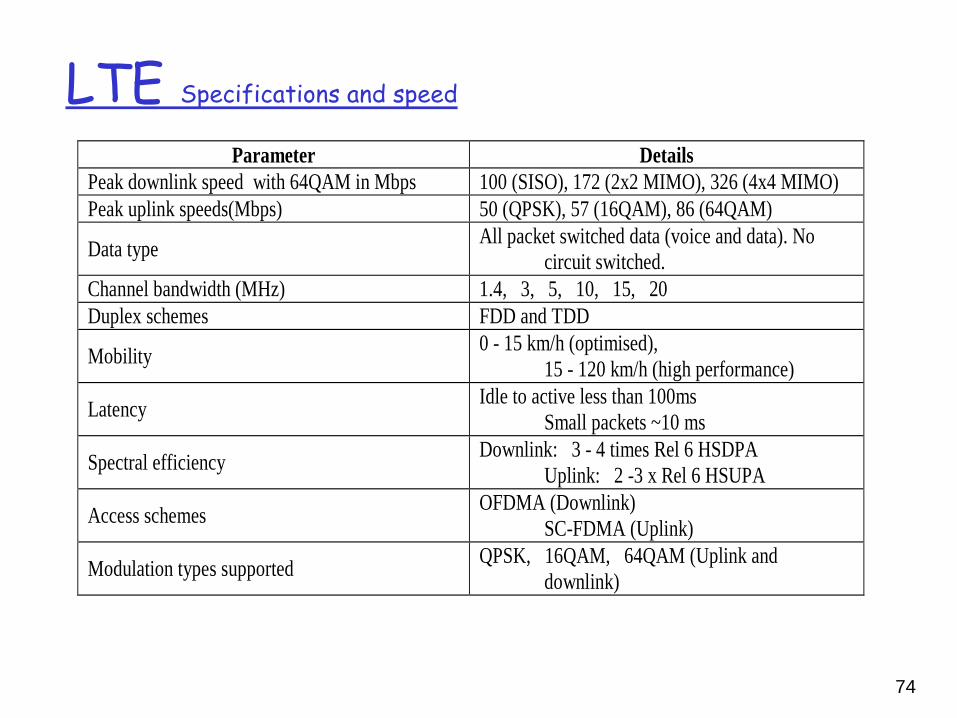
LTE Specifications and speed
Parameter Details Peak downlink speed with 64QAM in Mbps 100 (SISO), 172 (2x2 MIMO), 326 (4x4 MIMO) Peak uplink speeds(Mbps) 50 (QPSK), 57 (16QAM), 86 (64QAM)
Data type All packet switched data (voice and data). No circuit switched.
Channel bandwidth (MHz) 1.4, 3, 5, 10, 15, 20 Duplex schemes FDD and TDD
Mobility 0 - 15 km/h (optimised), 15 - 120 km/h (high performance)
Latency Idle to active less than 100ms Small packets ~10 ms
Spectral efficiency Downlink: 3 - 4 times Rel 6 HSDPA Uplink: 2 -3 x Rel 6 HSUPA
Access schemes OFDMA (Downlink) SC-FDMA (Uplink)
Modulation types supported QPSK, 16QAM, 64QAM (Uplink and downlink)
74
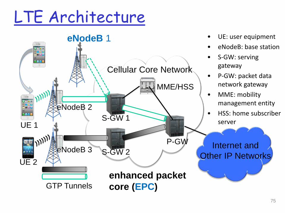
Cellular Core Network
eNodeB 3 S-GW 2P-GW
S-GW 1
eNodeB 1
eNodeB 2
Internet andOther IP Networks
GTP Tunnels
UE 2
UE 1
LTE Architecture• UE: user equipment• eNodeB: base station• S-GW: serving
gateway• P-GW: packet data
network gateway• MME: mobility
management entity• HSS: home subscriber
server
MME/HSS
enhanced packet core (EPC)
75
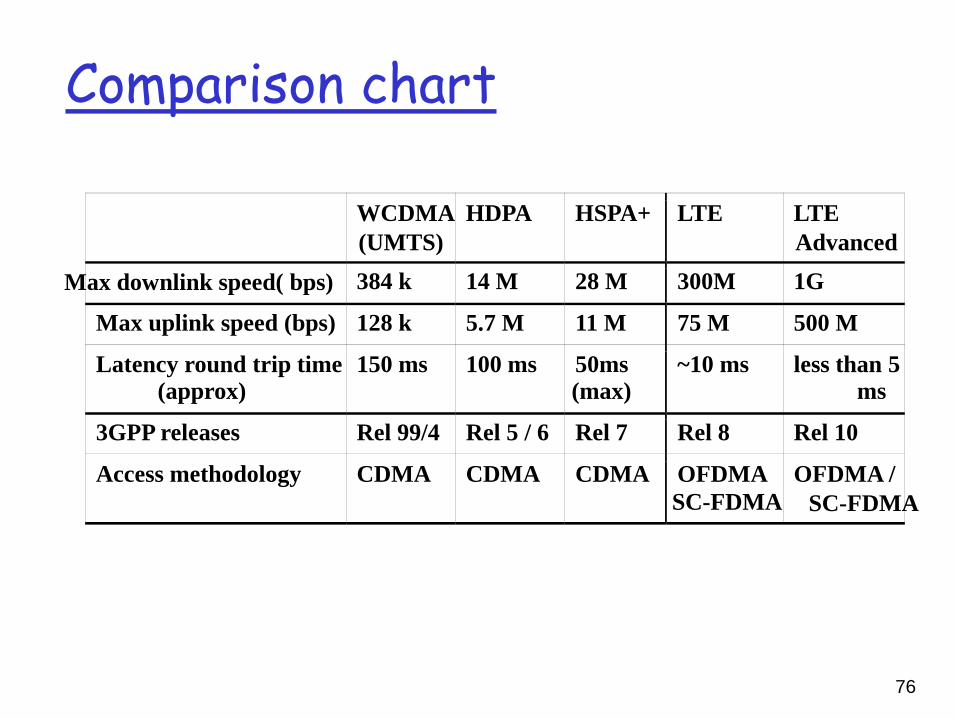
Comparison chart
WCDMA (UMTS)
HDPA HSPA+ LTE LTE Advanced
Max downlink speed( bps) 384 k 14 M 28 M 300M 1G
Max uplink speed (bps) 128 k 5.7 M 11 M 75 M 500 M
Latency round trip time(approx)
150 ms 100 ms 50ms (max)
~10 ms less than 5 ms
3GPP releases Rel 99/4 Rel 5 / 6 Rel 7 Rel 8 Rel 10
Access methodology CDMA CDMA CDMA OFDMA SC-FDMA
OFDMA / SC-FDMA
76
6: Wireless and Mobile Networks 6-77
Chapter 6 outline
6.1 Introduction
Wireless 6.2 Wireless links,
characteristics CDMA
6.3 IEEE 802.11 wireless LANs (“wi-fi”)
6.4 Cellular Internet Access architecture standards (e.g., GSM)
Mobility 6.5 Principles:
addressing and routing to mobile users
6.6 Mobile IP 6.7 Handling mobility in
cellular networks 6.8 Mobility and higher-
layer protocols
6.9 Summary
6: Wireless and Mobile Networks 6-78
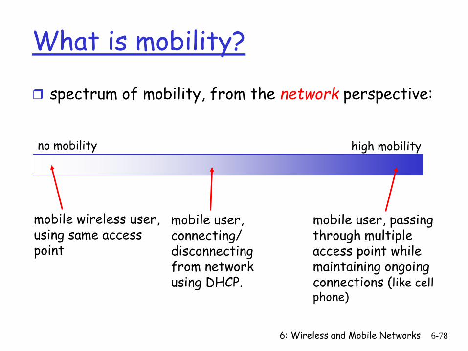
What is mobility?
spectrum of mobility, from the network perspective:
no mobility high mobility
mobile wireless user, using same access point
mobile user, passing through multiple access point while maintaining ongoing connections (like cell phone)
mobile user, connecting/ disconnecting from network using DHCP.
6: Wireless and Mobile Networks 6-79
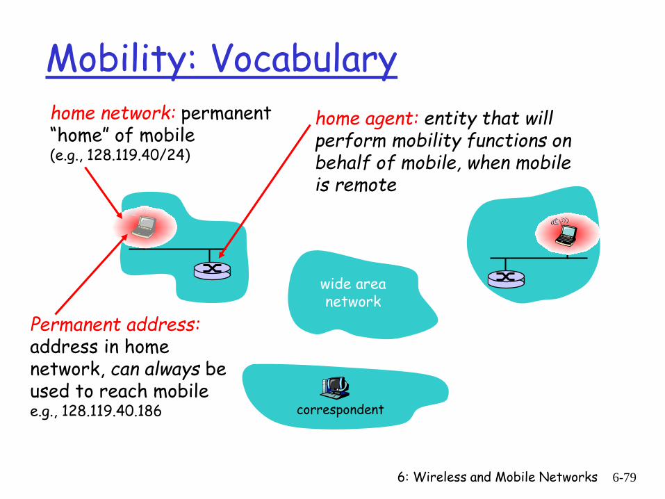
Mobility: Vocabularyhome network: permanent “home” of mobile(e.g., 128.119.40/24)
Permanent address:address in home network, can always be used to reach mobilee.g., 128.119.40.186
home agent: entity that will perform mobility functions on behalf of mobile, when mobile is remote
wide area network
correspondent
6: Wireless and Mobile Networks 6-80
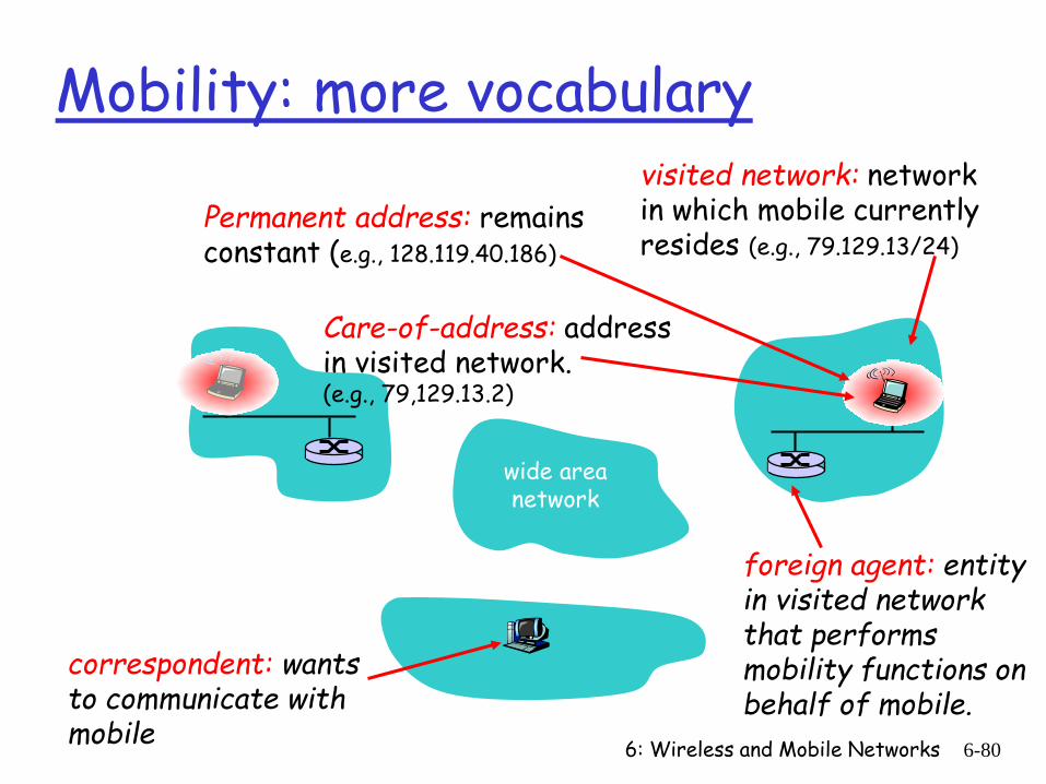
Mobility: more vocabulary
Care-of-address: address in visited network.(e.g., 79,129.13.2)
wide area network
visited network: network in which mobile currently resides (e.g., 79.129.13/24)
Permanent address: remains constant (e.g., 128.119.40.186)
foreign agent: entity in visited network that performs mobility functions on behalf of mobile.
correspondent: wants to communicate with mobile
6: Wireless and Mobile Networks 6-81
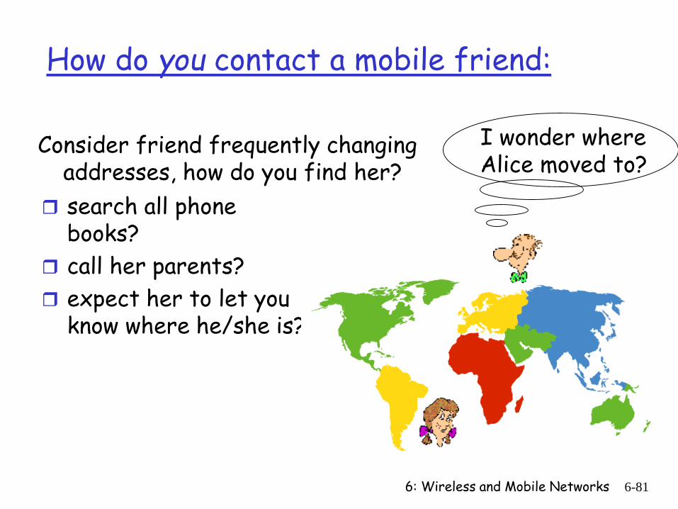
How do you contact a mobile friend:
search all phone books?
call her parents? expect her to let you
know where he/she is?
I wonder where Alice moved to?
Consider friend frequently changing addresses, how do you find her?
6: Wireless and Mobile Networks 6-82
Mobility: approaches
Let routing handle it: routers advertise permanent address of mobile-nodes-in-residence via usual routing table exchange. routing tables indicate where each mobile located no changes to end-systems
Let end-systems handle it: indirect routing: communication from
correspondent to mobile goes through home agent, then forwarded to remote
direct routing: correspondent gets foreign address of mobile, sends directly to mobile
6: Wireless and Mobile Networks 6-83
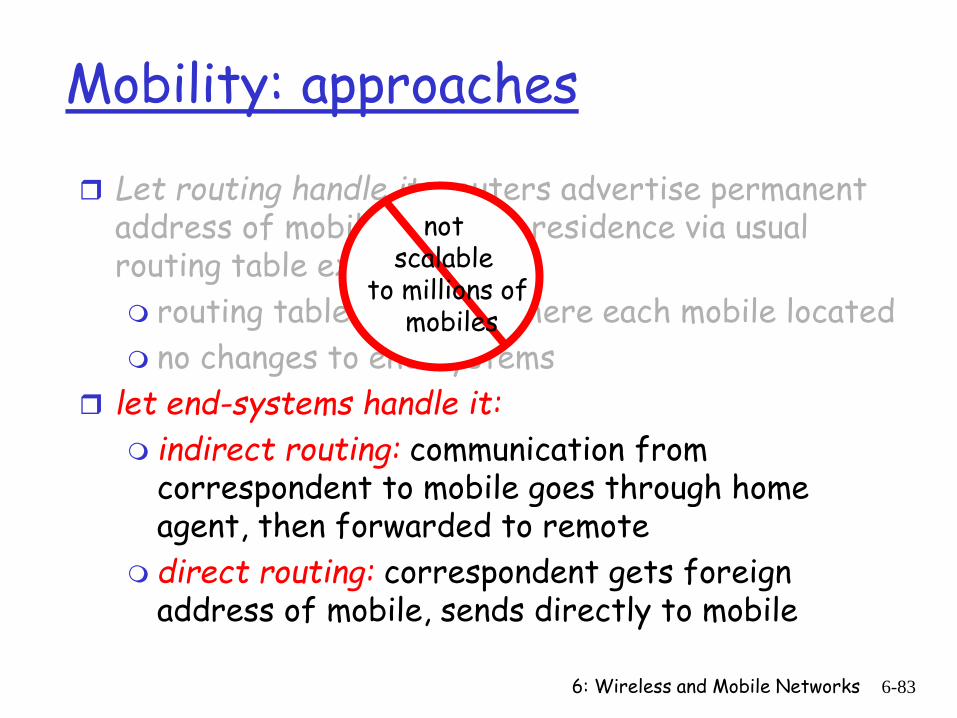
Mobility: approaches
Let routing handle it: routers advertise permanent address of mobile-nodes-in-residence via usual routing table exchange. routing tables indicate where each mobile located no changes to end-systems
let end-systems handle it: indirect routing: communication from
correspondent to mobile goes through home agent, then forwarded to remote
direct routing: correspondent gets foreign address of mobile, sends directly to mobile
not scalable
to millions ofmobiles
6: Wireless and Mobile Networks 6-84
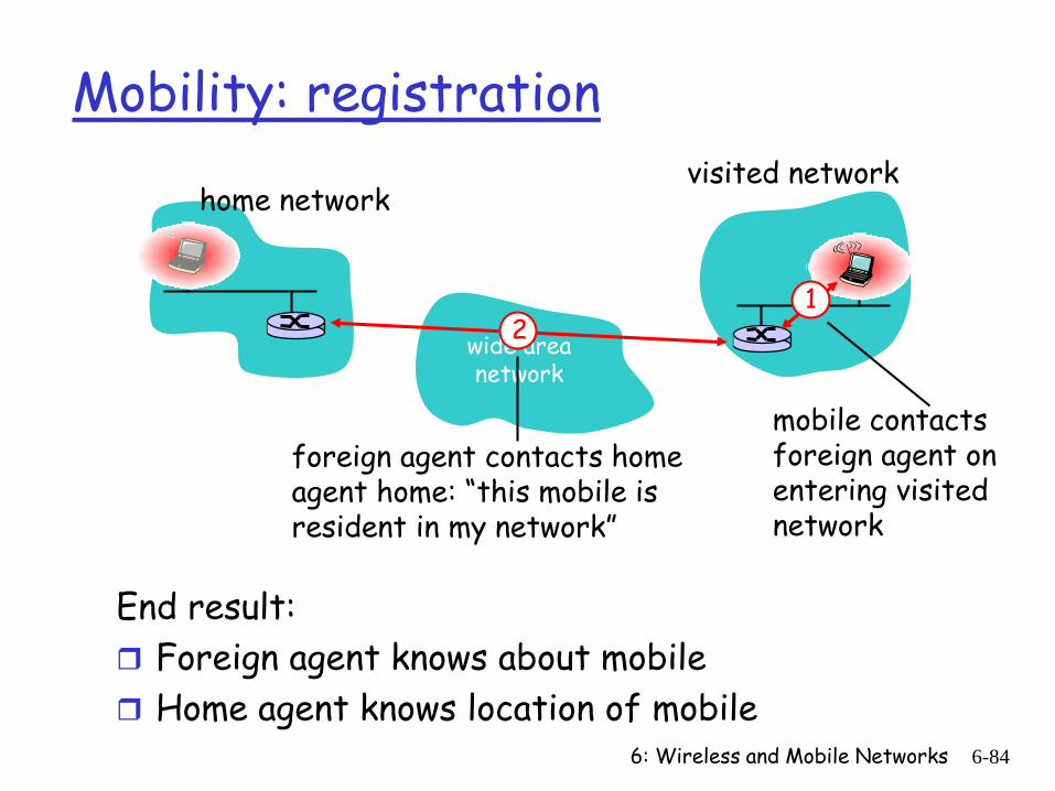
Mobility: registration
End result: Foreign agent knows about mobile Home agent knows location of mobile
wide area network
home networkvisited network
1
mobile contacts foreign agent on entering visited network
2
foreign agent contacts home agent home: “this mobile is resident in my network”
6: Wireless and Mobile Networks 6-85
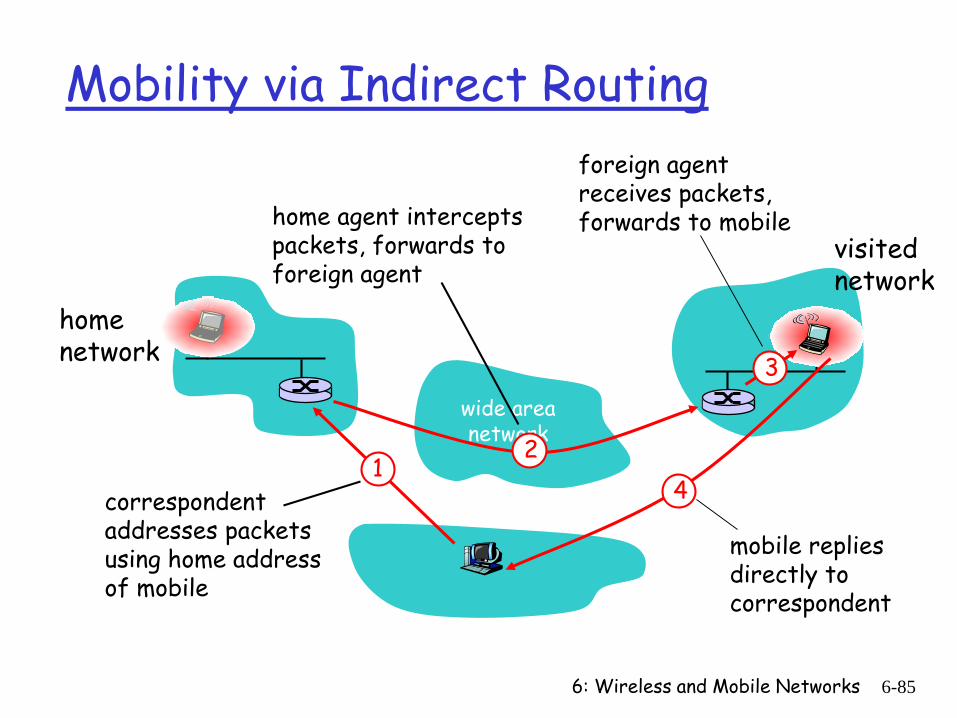
Mobility via Indirect Routing
wide area network
homenetwork
visitednetwork
3
24
1correspondent addresses packets using home address of mobile
home agent intercepts packets, forwards to foreign agent
foreign agent receives packets, forwards to mobile
mobile replies directly to correspondent
6: Wireless and Mobile Networks 6-86
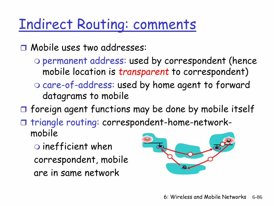
Indirect Routing: comments Mobile uses two addresses:
permanent address: used by correspondent (hence mobile location is transparent to correspondent)
care-of-address: used by home agent to forward datagrams to mobile
foreign agent functions may be done by mobile itself triangle routing: correspondent-home-network-
mobile inefficient when correspondent, mobile are in same network
6: Wireless and Mobile Networks 6-87
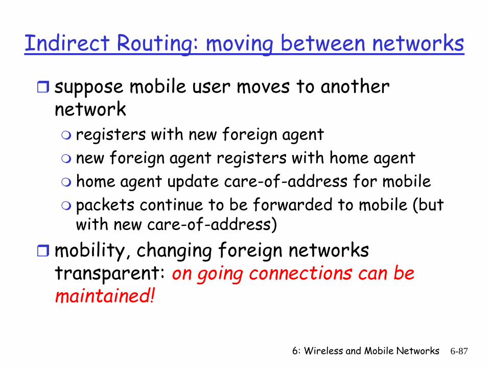
Indirect Routing: moving between networks
suppose mobile user moves to another network registers with new foreign agent new foreign agent registers with home agent home agent update care-of-address for mobile packets continue to be forwarded to mobile (but
with new care-of-address)mobility, changing foreign networks
transparent: on going connections can be maintained!
6: Wireless and Mobile Networks 6-88
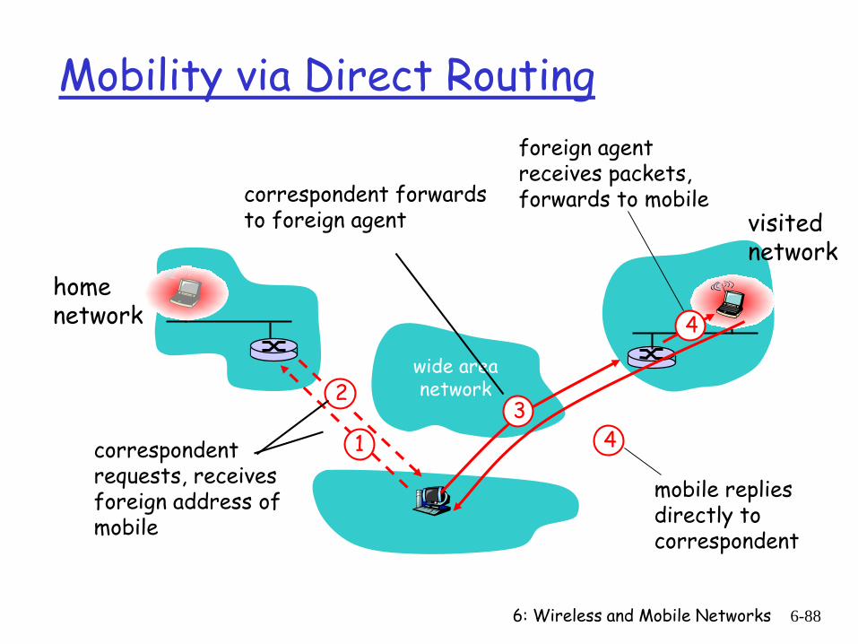
Mobility via Direct Routing
wide area network
homenetwork
visitednetwork
4
2
41correspondent requests, receives foreign address of mobile
correspondent forwards to foreign agent
foreign agent receives packets, forwards to mobile
mobile replies directly to correspondent
3
6: Wireless and Mobile Networks 6-89
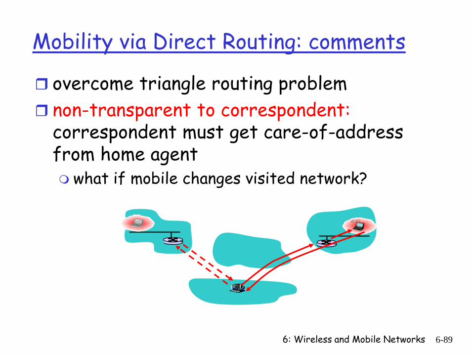
Mobility via Direct Routing: comments
overcome triangle routing problem non-transparent to correspondent:
correspondent must get care-of-address from home agent what if mobile changes visited network?
6: Wireless and Mobile Networks 6-90
wide area network
1
foreign net visited at session start
anchorforeignagent 2
4
new foreignagent
35
correspondentagent
correspondent
new foreignnetwork
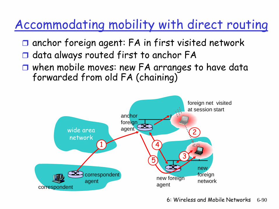
Accommodating mobility with direct routing anchor foreign agent: FA in first visited network data always routed first to anchor FA when mobile moves: new FA arranges to have data
forwarded from old FA (chaining)
6: Wireless and Mobile Networks 6-91
Chapter 6 outline
6.1 Introduction
Wireless 6.2 Wireless links,
characteristics CDMA
6.3 IEEE 802.11 wireless LANs (“wi-fi”)
6.4 Cellular Internet Access architecture standards (e.g., GSM)
Mobility 6.5 Principles:
addressing and routing to mobile users
6.6 Mobile IP 6.7 Handling mobility in
cellular networks 6.8 Mobility and higher-
layer protocols
6.9 Summary
6: Wireless and Mobile Networks 6-92
Mobile IP
RFC 3344 has many features we’ve seen:
home agents, foreign agents, foreign-agent registration, care-of-addresses, encapsulation (packet-within-a-packet)
three components to standard: indirect routing of datagrams agent discovery registration with home agent
6: Wireless and Mobile Networks 6-93
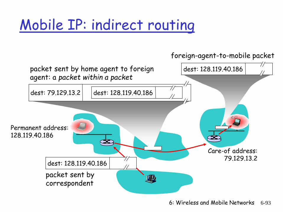
Mobile IP: indirect routing
Permanent address: 128.119.40.186
Care-of address: 79.129.13.2
dest: 128.119.40.186
packet sent by correspondent
dest: 79.129.13.2 dest: 128.119.40.186
packet sent by home agent to foreign agent: a packet within a packet
dest: 128.119.40.186
foreign-agent-to-mobile packet
6: Wireless and Mobile Networks 6-94
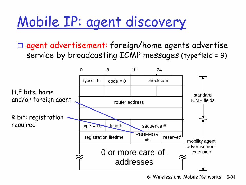
Mobile IP: agent discovery agent advertisement: foreign/home agents advertise
service by broadcasting ICMP messages (typefield = 9)
RBHFMGV bits reserved
type = 16
type = 9 code = 0
checksum
router address standard
ICMP fields
mobility agent advertisement
extension
length sequence #
registration lifetime
0 or more care-of-addresses
0 8 16 24
R bit: registration required
H,F bits: home and/or foreign agent
6: Wireless and Mobile Networks 6-95
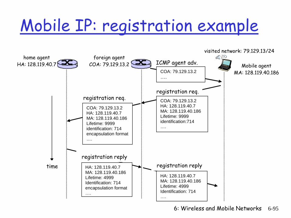
Mobile IP: registration example
visited network: 79.129.13/24 home agent
HA: 128.119.40.7 foreign agent
COA: 79.129.13.2 COA: 79.129.13.2
….
ICMP agent adv. Mobile agent MA: 128.119.40.186
registration req. COA: 79.129.13.2 HA: 128.119.40.7 MA: 128.119.40.186 Lifetime: 9999 identification:714 ….
registration req. COA: 79.129.13.2 HA: 128.119.40.7 MA: 128.119.40.186 Lifetime: 9999 identification: 714 encapsulation format ….
registration reply
HA: 128.119.40.7 MA: 128.119.40.186 Lifetime: 4999 Identification: 714 encapsulation format ….
registration reply
HA: 128.119.40.7 MA: 128.119.40.186 Lifetime: 4999 Identification: 714 ….
time
6: Wireless and Mobile Networks 6-96
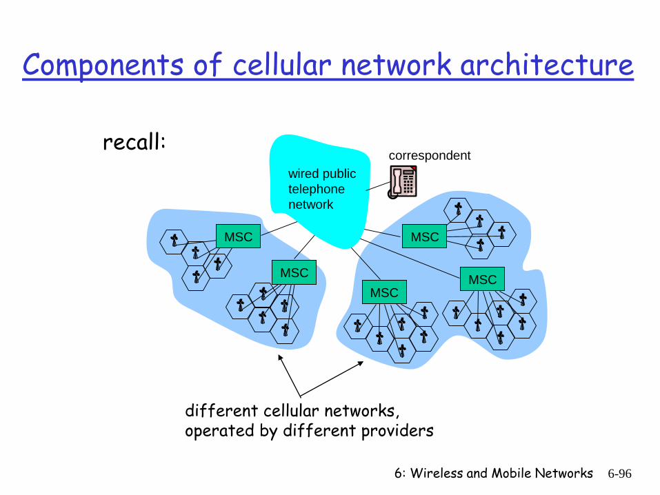
Components of cellular network architecture
correspondent
MSC
MSCMSC MSC
MSC
wired public telephonenetwork
different cellular networks,operated by different providers
recall:
6: Wireless and Mobile Networks 6-97
Handling mobility in cellular networks
home network: network of cellular provider you subscribe to (e.g., Sprint PCS, Verizon) home location register (HLR): database in home
network containing permanent cell phone #, profile information (services, preferences, billing), information about current location (could be in another network)
visited network: network in which mobile currently resides visitor location register (VLR): database with
entry for each user currently in network could be home network
6: Wireless and Mobile Networks 6-98
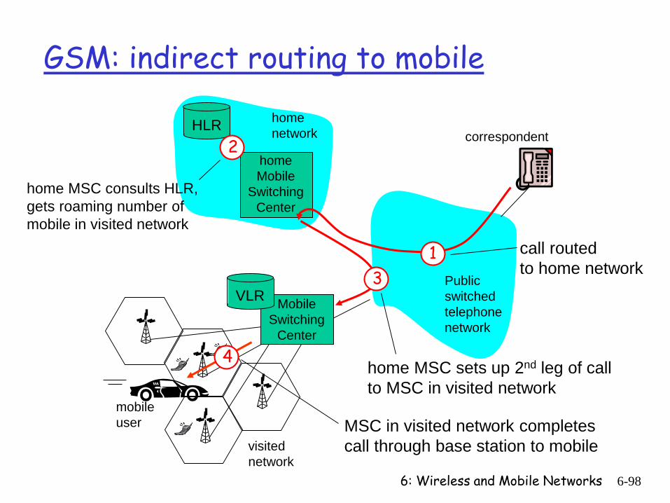
Public switched telephonenetwork
mobileuser
homeMobile
Switching Center
HLR home network
visitednetwork
correspondent
Mobile Switching
Center
VLR
GSM: indirect routing to mobile
1 call routed to home network
2
home MSC consults HLR,gets roaming number ofmobile in visited network
3
home MSC sets up 2nd leg of callto MSC in visited network
4
MSC in visited network completescall through base station to mobile
6: Wireless and Mobile Networks 6-99
Mobile Switching
Center
VLR
old BSSnew BSS
old routing
newrouting
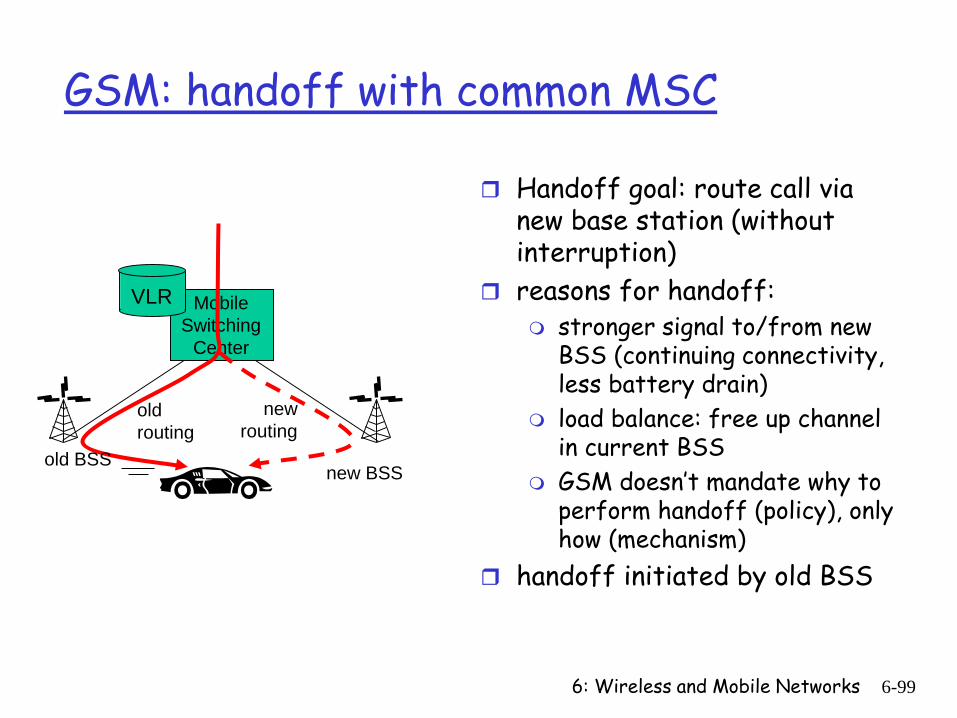
GSM: handoff with common MSC
Handoff goal: route call via new base station (without interruption)
reasons for handoff: stronger signal to/from new
BSS (continuing connectivity, less battery drain)
load balance: free up channel in current BSS
GSM doesn’t mandate why to perform handoff (policy), only how (mechanism)
handoff initiated by old BSS
6: Wireless and Mobile Networks 6-100
Mobile Switching
Center
VLR
old BSS
1
3
24
5 6
78
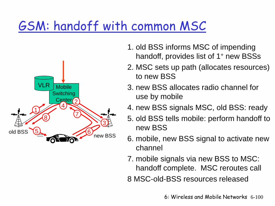
GSM: handoff with common MSC
new BSS
1. old BSS informs MSC of impending handoff, provides list of 1+ new BSSs
2. MSC sets up path (allocates resources) to new BSS
3. new BSS allocates radio channel for use by mobile
4. new BSS signals MSC, old BSS: ready 5. old BSS tells mobile: perform handoff to
new BSS6. mobile, new BSS signal to activate new
channel7. mobile signals via new BSS to MSC:
handoff complete. MSC reroutes call8 MSC-old-BSS resources released
6: Wireless and Mobile Networks 6-101
home network
Home MSC
PSTN
correspondent
MSCanchor MSC
MSCMSC
(a) before handoff
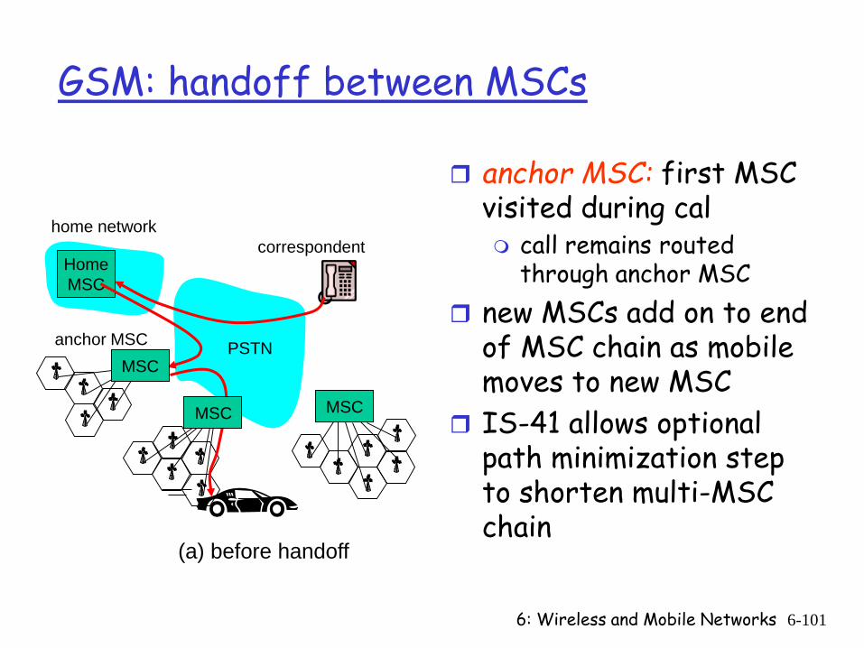
GSM: handoff between MSCs
anchor MSC: first MSC visited during cal call remains routed
through anchor MSC new MSCs add on to end
of MSC chain as mobile moves to new MSC
IS-41 allows optional path minimization step to shorten multi-MSC chain
6: Wireless and Mobile Networks 6-102
home network
Home MSC
PSTN
correspondent
MSCanchor MSC
MSCMSC
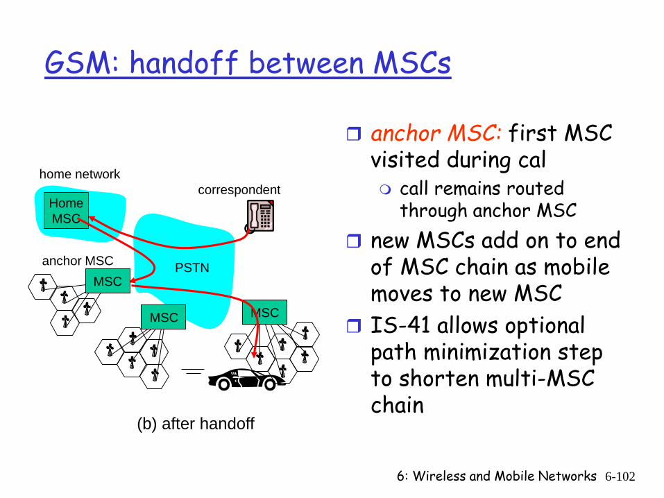
(b) after handoff
GSM: handoff between MSCs
anchor MSC: first MSC visited during cal call remains routed
through anchor MSC new MSCs add on to end
of MSC chain as mobile moves to new MSC
IS-41 allows optional path minimization step to shorten multi-MSC chain
6: Wireless and Mobile Networks 6-103
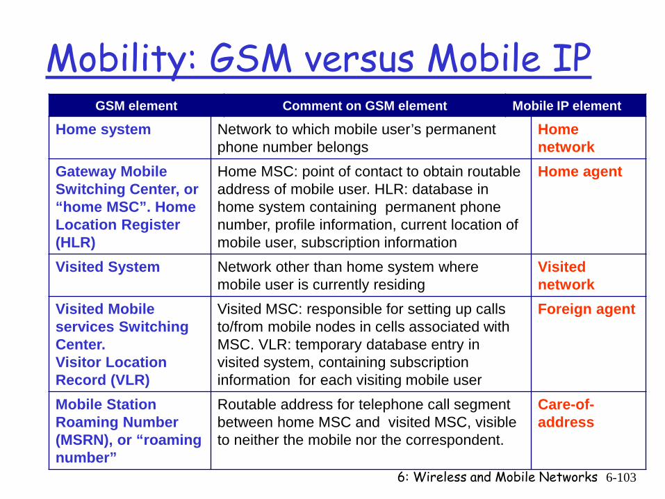
Mobility: GSM versus Mobile IPGSM element Comment on GSM element Mobile IP element
Home system Network to which mobile user’s permanent phone number belongs
Home network
Gateway Mobile Switching Center, or “home MSC”. Home Location Register (HLR)
Home MSC: point of contact to obtain routable address of mobile user. HLR: database in home system containing permanent phone number, profile information, current location of mobile user, subscription information
Home agent
Visited System Network other than home system where mobile user is currently residing
Visited network
Visited Mobile services Switching Center.Visitor Location Record (VLR)
Visited MSC: responsible for setting up calls to/from mobile nodes in cells associated with MSC. VLR: temporary database entry in visited system, containing subscription information for each visiting mobile user
Foreign agent
Mobile Station Roaming Number (MSRN), or “roaming number”
Routable address for telephone call segment between home MSC and visited MSC, visible to neither the mobile nor the correspondent.
Care-of-address
6: Wireless and Mobile Networks 6-104
Wireless, mobility: impact on higher layer protocols
logically, impact should be minimal … best effort service model remains unchanged TCP and UDP can (and do) run over wireless, mobile
… but performance-wise: packet loss/delay due to bit-errors (discarded
packets, delays for link-layer retransmissions), and handoff
TCP interprets loss as congestion, will decrease congestion window un-necessarily
delay impairments for real-time traffic limited bandwidth of wireless links
6: Wireless and Mobile Networks 6-105
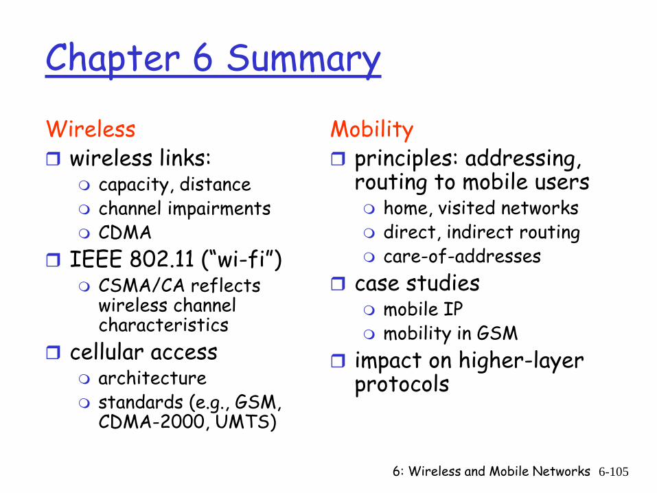
Chapter 6 Summary
Wireless wireless links:
capacity, distance channel impairments CDMA
IEEE 802.11 (“wi-fi”) CSMA/CA reflects
wireless channel characteristics
cellular access architecture standards (e.g., GSM,
CDMA-2000, UMTS)
Mobility principles: addressing,
routing to mobile users home, visited networks direct, indirect routing care-of-addresses
case studies mobile IP mobility in GSM
impact on higher-layer protocols
Supplementary slides
6: Wireless and Mobile Networks 6-106
6: Wireless and Mobile Networks 6-107
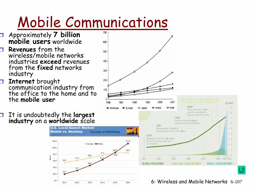
Mobile Communications
Use
rs/m
illion
s
Approximately 7 billion mobile users worldwide
Revenues from the wireless/mobile networks industries exceed revenues from the fixed networks industry
Internet brought communication industry from the office to the home and to the mobile user
It is undoubtedly the largestindustry on a worldwide scale
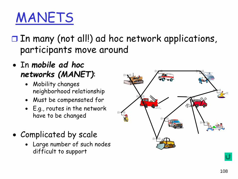
MANETS In many (not all!) ad hoc network applications,
participants move around • In mobile ad hoc
networks (MANET):• Mobility changes
neighborhood relationship • Must be compensated for• E.g., routes in the network
have to be changed
• Complicated by scale• Large number of such nodes
difficult to support
108
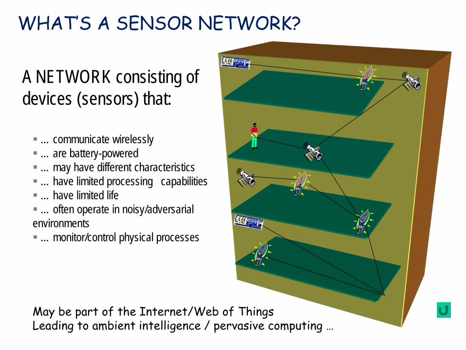
A NETWORK consisting of devices (sensors) that:
… communicate wirelessly… are battery-powered… may have different characteristics… have limited processing capabilities… have limited life… often operate in noisy/adversarial environments… monitor/control physical processes
WHAT’S A SENSOR NETWORK?
May be part of the Internet/Web of ThingsLeading to ambient intelligence / pervasive computing …
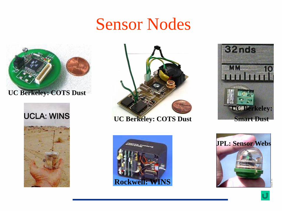
UC Berkeley: COTS Dust
UC Berkeley: COTS DustUC Berkeley: Smart DustUCLA: WINS
Rockwell: WINS
JPL: Sensor Webs
Sensor Nodes
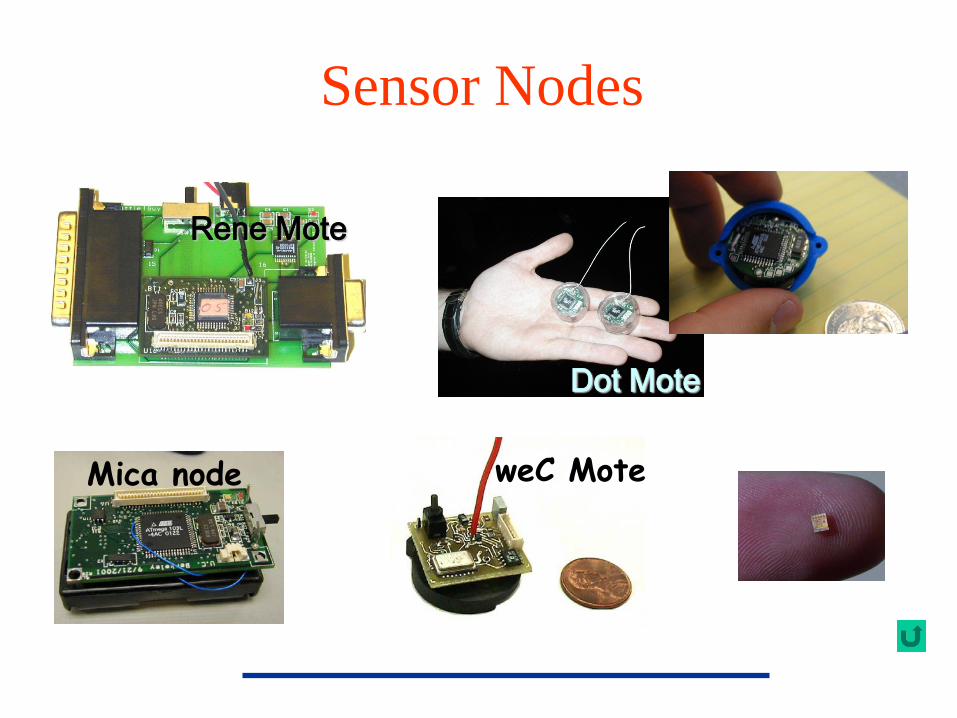
Rene Mote
Dot Mote
weC MoteMica node
Sensor Nodes
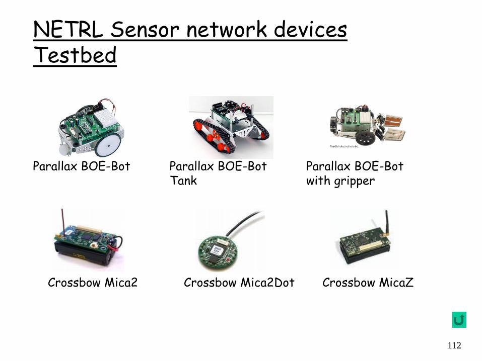
NETRL Sensor network devices Testbed
Crossbow Mica2 Crossbow MicaZCrossbow Mica2Dot
Parallax BOE-Bot Parallax BOE-Bot Tank
Parallax BOE-Bot with gripper
112
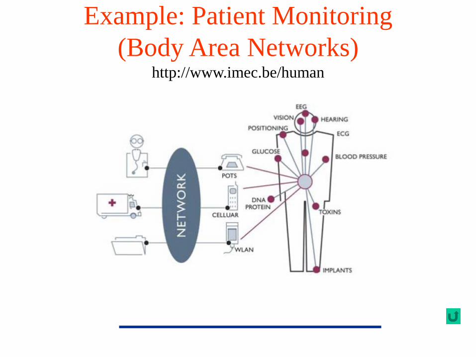
Example: Patient Monitoring(Body Area Networks)
http://www.imec.be/human
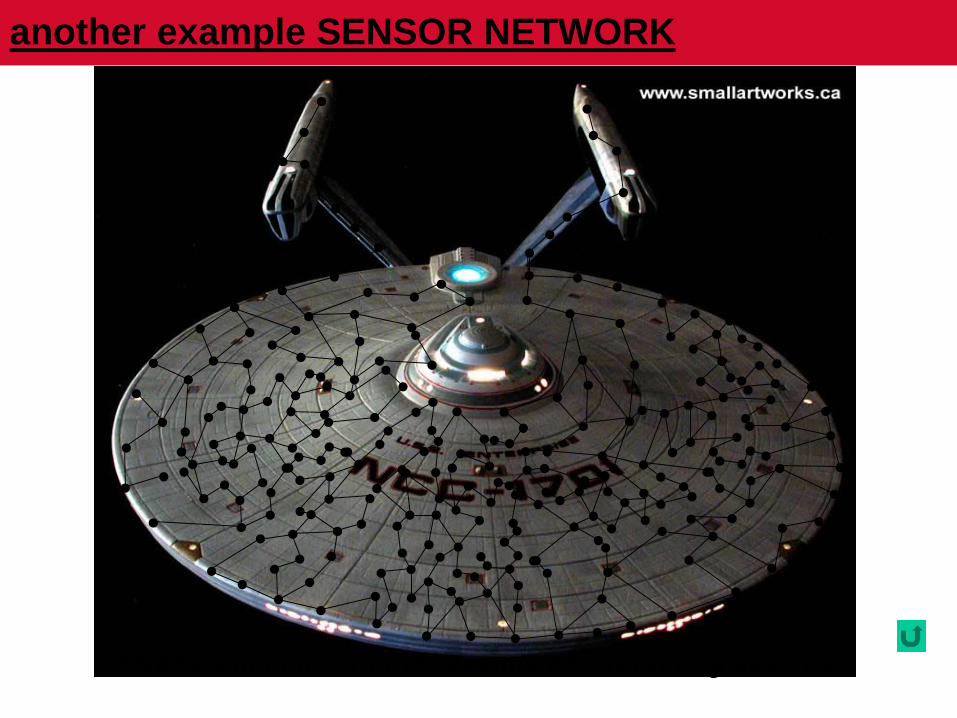
another example SENSOR NETWORK
SNETs will consist of thousands of interacting devices!
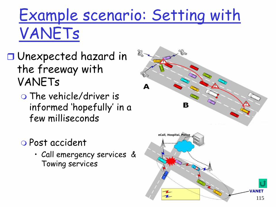
Example scenario: Setting with VANETs
Unexpected hazard in the freeway with VANETs The vehicle/driver is
informed ‘hopefully’ in a few milliseconds
Post accident• Call emergency services &
Towing services
115