Embed Size (px)
Citation preview
1
SUKHOISU-27
for 2 AMT Mercuryor 2 RAM 1000 / 750
or 2 Jet CAT P 80 / 120
Assembly Manual
������������ ������������ ������������ ������������
ZI le chenet, 91490 Milly La Foret, FRANCETel : 33 1 64 98 93 93Fax : 33 1 64 98 93 88
E-mail : [email protected]
Version 15/11/2002

2
INTRODUCTION
The Su-27 from ��������������� is designed for high thrust jet engines.It is a scale kit, with all the panel lines engraved in the fuselage and a lot of scale details (gears, hinges,cockpit...). It is fully molded in fiberglass, carbon and epoxy. Up to 80% of the work is done in ourfactory.The flight characteristics are excellent with low and high speed capability.The model has plug in wings, stabs and fins.The Sukhoi will operate from prepared grass fields (70 meters long) or tarmac surfaces.
KIT FEATURES
- High quality, grey gel-coated epoxy-glass fuselage. All the panel lines are engraved. The fuselage is in 2parts for shipping.
- Nose cone and central tail boom in epoxy glass- Air brake molded in epoxy-glass- Main gear doors- Canopy frame molded in epoxy-glass- 2 Exhaust nozzle.- 2 Epoxy-glass inlets- 2 Epoxy-glass ductings- Fully molded epoxy carbon wings and stabs with aluminium spar already glued.- Fully molded epoxy carbon fins with aluminium spar already glued- 2 ventral fin in epoxy- Wing tip rails- All plywood and wood parts pre-cut to shape where necessary.- Air cylinder for air brake.- All hardware necessary.
Following items are included in the kitFor the fuselage :a set of screws + blind nuts for the gearFor the canopy, 1hatch latchFor the air brake, 1air cylinder + tubing and air valveFor the stabs :4 ball bearing for the stabs4 ball bearing mounting8 screws M3x16 mm long2 aluminium link M42 threaded rod M42 carbon control horns
- ABS cockpit interior and scale accessories.- Clear formed canopy.- Cockpit detail kit include 1/8 full body jet pilot, 1/8 ejector seat & instrument panel.- pitot probes and incidence probes.- vacuum parts- instructions in English and plan.
To complete the kit :The following items are not included in the kit. They are available from ���������������.
3
Landing gear + gear doors kit : ref : ADJ 410 for the Su 27
������� ���� scale retractable landing gear is specially designed for the Sukhoi.It is made in aluminium and include also plastic partsFor the gear, it includes 3 rotating retracts system, 3 oleo legs, 4 way valve, tubing, connectors, air tank,filling valve, ...For the doors, it includes 3 air cylinders, electronic gear door cycler (3 chanels), 4 way valve, tubing,connectors, air tank, door hinges, ball linksIt includes also 2 x 125 mm diameter wheels + scale cover + brakes and 1 x 88 mm diameter front wheelIt includes valve, tubing, connectors, air tank, filling valve.
Kevlar Fuel tanks : ref ADJ 4502 Fuels cells molded in kevlar. Capacity : 2 x 2.4 litersIt includes also all tubing and upper tank
Variable pressure brake control valve : ref : ADT Brk
2 stainless steel tailpipe : ref : ADJ 460
Jet Engines :2 Complete AMT Mercury jet enginesor 2 RAM 750 or RAM 1000 jet enginesor 2 Jet Cat P120 jet engines
Not included in the different package :0.3 kg epoxy and glass fiberZAP CA
DISCLAIMER
������������ assumes no liability for the operation and use of these products.The owner and operator of these products should have the necessary experience and exercise commonsense. Said owner and operator must have a valid Model Airplane license and insurance, as required.
FIBREGLASS PREPARATIONThe inside of the fuselage should be sanded with fresh #80 grit paper for best glue adhesion wherebulkheads and other attachments are fixed.
GLUING TECHNIQUESAll the plywood formers should be fitted with cyano adhesive and then glued with epoxy and glass fibertape. All other parts should be glued with epoxy.

4
CONSTRUCTION
Front FUSELAGE
Gear doors :Cut just one side off the front gear door according to the engraved panel lines.Glue the 3 door hinges with cyano (take care of the position according to the plan).
Finish to cut the front gear door 15 mm longer than the engraved panel lines ( 10 mm forward, 5 mmbackward).
Make 2 fence in the front gear door according to the engraved panel line
Glues with CA the plastic vacuum parts in the front gear door

5
Frame :Assemble the frame C1, C2 and C3
Desassemble them , fit them in the fuselage and assemble them.
Glue them in the fuselage according to the plan (check distance between the C2 former and the fuselageend)
Epoxy the bulkheads in place : the 2 formers must be glued with epoxy and glass fiber.Cut some glassfibre tapes (30 mm large and 10 cm long).Glue this tape with epoxy overlapping all the formers and the fuselage.Let them dry overnight.

6
Rear FUSELAGE
Cut the 2 gear doors according to the engraved panel lines.Also cut some 4 mm larg slot for the wood location, according to the photos and line drawn on the fuselage
Gear frame :
Drill the 4 mm holes in C10Insert 4 M3 blind nuts
Screw the aluminium gear block on C10 with 2x M3 x 12 alen screwDrill bigger (4 mm diameter) the 4 holes in the air cylinder steel mounting.Screw the air cylinder on C15 and on C10 with 2x M3x16 philips screwBut don’t tighten it too much so that the air cylinder can have a little play up and down
Screw the air cylinder ball link on the aluminium pivot with 1 M3x 16 alen screw.

7
Insert the locking air cylinder in the aluminium gear block.Screw the small air cylinder and C16 on C10 with 2x16 parker screw.Check that it lock the gear when it is extended and it unlock the gear when it is retracted.Glue C16 on C10
Assemble the frame C10, C11, C12 and C13Fit them in the fuselage and assemble them.Insert C14 in the fuselage and drill a 3 mm hole throught the aluminium bock, the fuselage and C14Remove C14 and increse the hole diameter to 4 mmInsert a M3 blind nut
Epoxy all the bulkheads in place : C10, C11, C12, C13, C14 must be glued with epoxy and glass fiber.

8
Cut some glassfibre tapes (30 mm large and 5 cm long).Glue this tape with epoxy overlapping all the formers and the fuselage.
Screw the gear box to C14 with M3x12 alen screw puting some epoxy on C14.
Insert some tape IN the fuselage overlapping all the formers and the fuselage.Check to glue very strongly C14 in the fuselage against the main fraime
Let them dry overnight.
Rear frame and bearing installation :
Cut out all hatches and make the necessary holes in the fuselage according to the photos.Cut the back of the fuselage at the bearing position.
Cut the slot (6 mm larg, 20 mm height) in the fuselage (fin root location) for the elevator control hornIt will be covered by the finGlue the bearing in the mounting with threadlock glue.Screw the 4 bearing mounting to the rear fuselage with M3x16 alen screw.
9
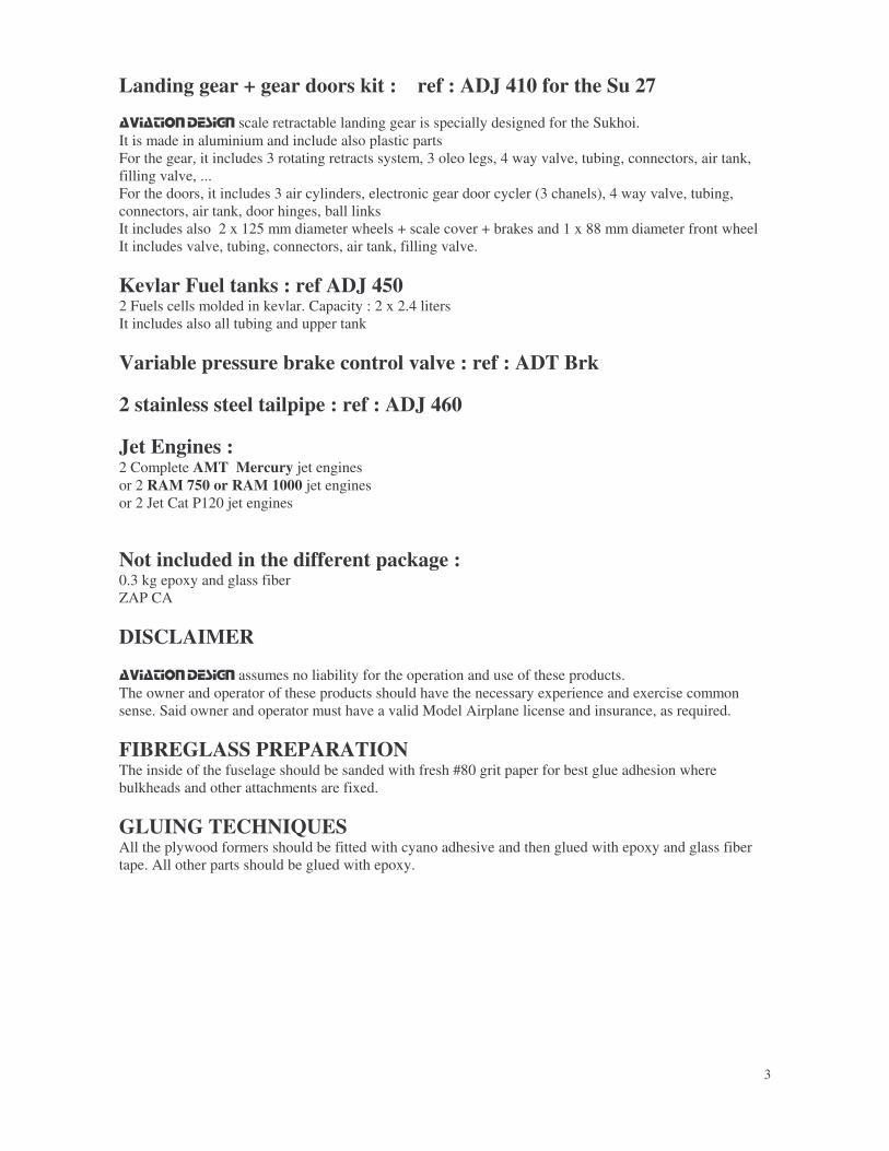
Screw the 2 servos (9 kg.cm torque) on each plywood frame C20.
Connect the 2 servos together and try them with your radio. They must move without any bad noise
Insert them in the fuselage.
Check that they can move without problem.
Glue C20 with CA for the moment.
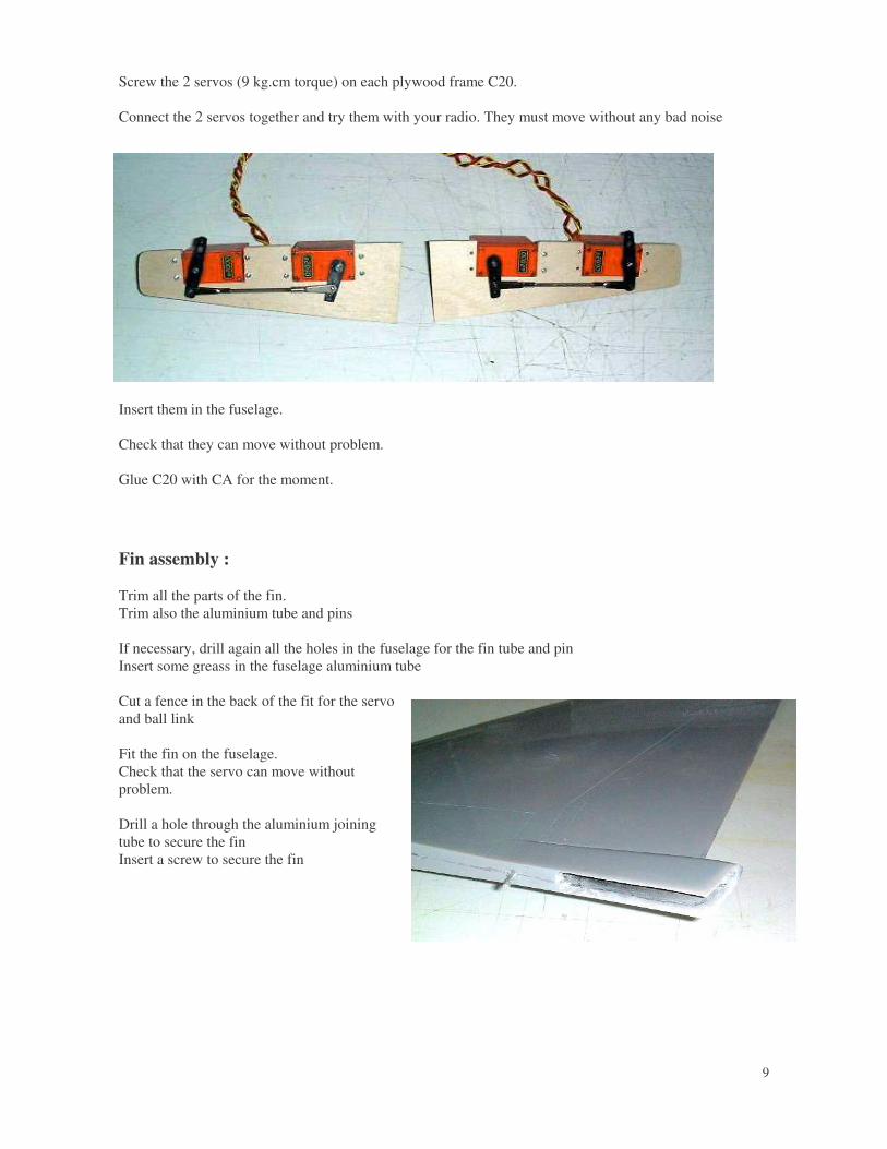
Fin assembly :
Trim all the parts of the fin.Trim also the aluminium tube and pins
If necessary, drill again all the holes in the fuselage for the fin tube and pinInsert some greass in the fuselage aluminium tube
Cut a fence in the back of the fit for the servoand ball link
Fit the fin on the fuselage.Check that the servo can move withoutproblem.
Drill a hole through the aluminium joiningtube to secure the finInsert a screw to secure the fin
10
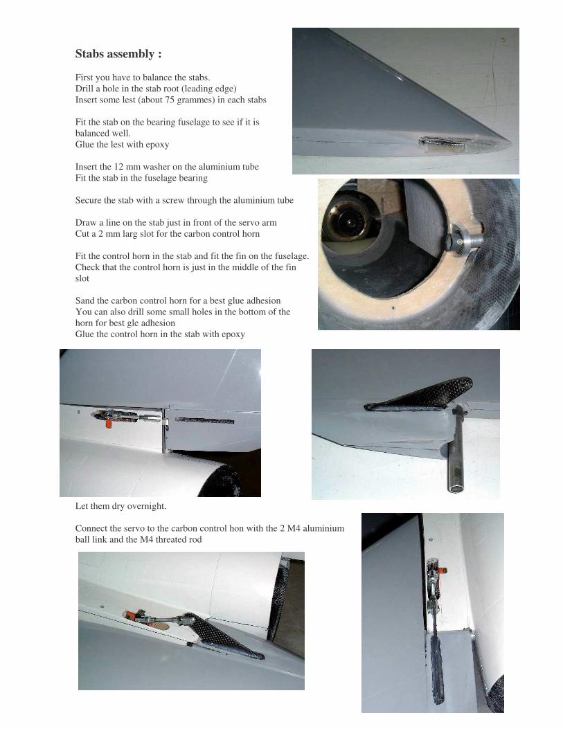
Stabs assembly :
First you have to balance the stabs.Drill a hole in the stab root (leading edge)Insert some lest (about 75 grammes) in each stabs
Fit the stab on the bearing fuselage to see if it isbalanced well.Glue the lest with epoxy
Insert the 12 mm washer on the aluminium tubeFit the stab in the fuselage bearing
Secure the stab with a screw through the aluminium tube
Draw a line on the stab just in front of the servo armCut a 2 mm larg slot for the carbon control horn
Fit the control horn in the stab and fit the fin on the fuselage.Check that the control horn is just in the middle of the finslot
Sand the carbon control horn for a best glue adhesionYou can also drill some small holes in the bottom of thehorn for best gle adhesionGlue the control horn in the stab with epoxy
Let them dry overnight.
Connect the servo to the carbon control hon with the 2 M4 aluminiumball link and the M4 threated rod

11
Air brake :
Fit the air brake on the fuselage.Draw a line on the fuselage at 18 mm from the fuselage edge
Cut 2 slots in the air brake location fuselageCheck that the air brake can move without problem in this slot
Fit the air brake on the fuselage.Drill a 2 mm diameter hole through the fuselage and the airbrake just on the lineTake care that the 2 side holes are parallel
Fit a 2 mm piano wire through the fuselage and the air brakeAnd check that it can move without problem
For the air cylinder location, Cut a slot in the top of thefuselage according to the plan
Fit a 2 mm piano wire in the cylinder hole and glue the pianowire IN the fuselage according to the plan
Cut a slot in the air brake according to the plan
Glue the plywood control horn C24 in the air brake with epoxy
Fit the air brake on the fuselage with the piano wireConnect the air cylinder to the control horn with thealuminium link

12
Air intakes
Glue with epoxy the plywood reinforcement C26
Cut the air intakes as engraved
Fit the air intake on the fuselage.Drill a 3 mm hole throught the plywood reinforcement and the fuselageInsert a 3 mm screw
Insert M3 blind nut in C25Glue with epoxy C25 in the fuselage
Screw the air intake on the fuselage with a M3 screw
Drill 4 x 2 mm holes through the intake and C10
Screw the 4 parker screws
Unscrew the air intake from the fuselage. You will havenow to glue the ducting in the air intake
Cut the back of the ducting so that it will not touch theengine mounting frame.
Fit the ducting in the air inlet and glue the leading edgewith epoxy and microballonGlue also the rear of the ducting to the air intakePut some clothes pegs all around the intake leading eadgeduring drying.Let them dry overnight.Trim all the leading edge.

13
Gear doors
Cut the main gear doors in 3 parts
Cut 2 slots in the fuselage as engraved for the 2Robart door hinges.
Glue the 2 Robart hinges against the fuselage withCA, just in front of the 2 slots.They must be outside of the fuselage.
Glue the plywood reinforcement C28 on the main gear door with quick epoxyPut 4 cloth pegs
Glue the 2 hinges on the gear door with epoxy. Adjust carefully them so that the gear door is in front of thefuselage hole Secure the hinges with 2 parker screw and plywood reinforcement C29 inside
14
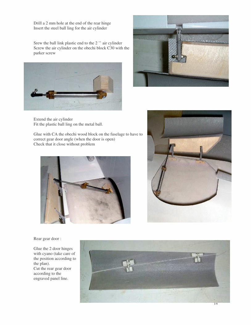
Drill a 2 mm hole at the end of the rear hingeInsert the steel ball ling for the air cylinder
Srew the ball link plastic end to the 2 ’’ air cylinderScrew the air cylinder on the obechi block C30 with theparker screw
Extend the air cylinderFit the plastic ball ling on the metal ball.
Glue with CA the obechi wood block on the fuselage to have tocorrect gear door angle (when the door is open)Check that it close without problem
Rear gear door :
Glue the 2 door hingeswith cyano (take care ofthe position according tothe plan).Cut the rear gear dooraccording to theengraved panel line.

15
Glue with CA the fix piece on the fuselage
Check that it can open and close without problem
Fit a spring on the rear door hinges so that thedoor automatically close when the gear goes up.
Wings:
Cut the location of the 2 gear doors hingesin the wing according to the engraved panelline.
Wing tip missile rails :
Fit the wing tip missile rails with 2 parker screws 3x20

16
Drill a hole (about 15 mm diameter) in the top of themain frame for the electric wire and air tubing
Landing Gear :
Main gear :
You have now to connect all the gear, door and braketubing.
Fit the main oleo legs in the retracts. Check that the 2wheels are parallel.Drill a 2.5 mm hole through the oleo legs and the maingearInsert a M3 screw.
Retract and extend the legs to check that the wheels fitwell in the fuselage.
Front gear
Screw the front landing gear on C2Fit the steering control arm + the oleo legs on the retractsGlue the ABS cover on the wheel hole
17
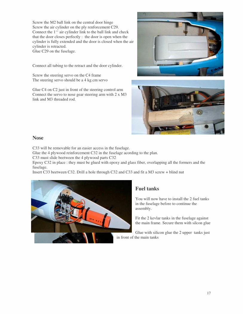
Screw the M2 ball link on the central door hingeScrew the air cylinder on the ply renforcement C29.Connect the 1‘‘ air cylinder link to the ball link and checkthat the door closes perfectly : the door is open when thecylinder is fully extended and the door is closed when the aircylinder is retracted.Glue C29 on the fuselage.
Connect all tubing to the retract and the door cylinder.
Screw the steering servo on the C4 frameThe steering servo should be a 4 kg.cm servo
Glue C4 on C2 just in front of the steering control armConnect the servo to nose gear steering arm with 2 x M3link and M3 threaded rod.
Nose
C33 will be removable for an easier access in the fuselage.Glue the 4 plywood reinforcement C32 in the fuselage acording to the plan.C33 must slide beetween the 4 plywood parts C32Epoxy C32 in place : they must be glued with epoxy and glass fiber, overlapping all the formers and thefuselage.Insert C33 beetween C32. Drill a hole through C32 and C33 and fit a M3 screw + blind nut
Fuel tanks
You will now have to install the 2 fuel tanksin the fuselage before to continue theassembly.
Fit the 2 kevlar tanks in the fuselage againstthe main frame. Secure them with silcon glue
Glue with silicon glue the 2 upper tanks justin front of the main tanks

18
Assemble the fuselage
You have now to assemble the 2 part of the fuselage together.
If you have a Su 27, you can only screw the 2 parts together. It will be easier later to repair any damage.
Fit the 2 parts in front of each other.Drill a 15 x 1.5 mm hole through the 2 parts to insert parker screw.
If you want only to screw the fuselage together (disassemble later),glue 15 x 3 mm plywood reinforcement on the hole location.Screw the 2 parts with 15 parker screws.
If you glue the 2 parts, put some epoxy on both side.Fit the 2 parts together and screw au the parker screw. Let it dryovernight. Remove the screw after drying.
Assemble the central tail boom
If you want, you can only screw the 2parts together. It will be easier forhandling.But it is also possible to glue it.
Fit the 2 parts in front of each other.Drill a 6 x 1.5 mm hole through the 2parts to insert parker screw.Glue 6 x 3 mm plywood reinforcementon the hole location.Screw the 2 parts with 6 parker screws

19
CANOPY :
Front canopy :Cut the front fiberglass canopyCut the clear canopy in 2 partsCut the front clear canopy according to theengraged lineGlue the glear canopy INSIDE the fuselagewith Zap canopy glueLet it dry overnight.Cut the front vacuum part. Paint it in blackGlue it inside the front canopy with Zapcanopy glueLet it dry overnight.
Glue the on the canopy with canopy with Zap canopy glue
Rear canopy :
Cut the rear fiberglass canopy from thecanopy frameCut the rear clear canopy according to theengraged lineGlue the glear canopy INSIDE the canopyframe with Zap canopy glueLet it dry overnight.Cut the rear vacuum part. Paint it in greyGlue it inside the canopy frame with Zapcanopy glueLet it dry overnight.
Insert the hatch latch in the fuselage tosecure the canopy frame on the fusleage.
20
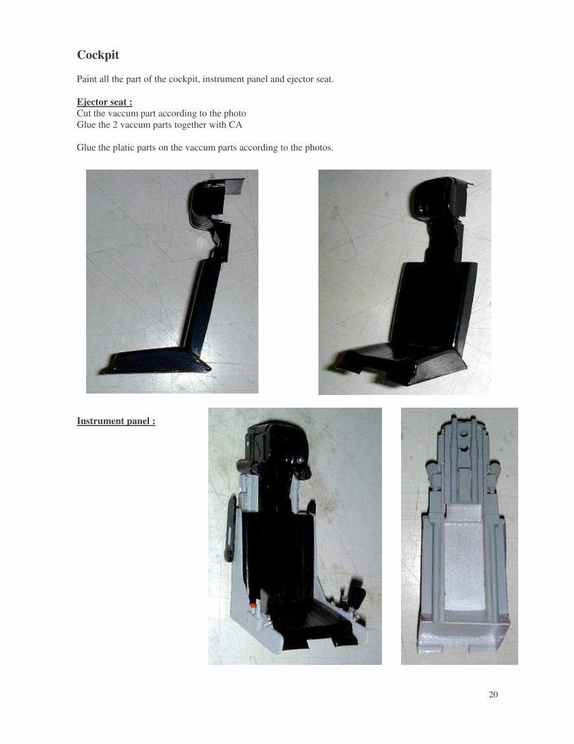
Cockpit
Paint all the part of the cockpit, instrument panel and ejector seat.
Ejector seat :Cut the vaccum part according to the photoGlue the 2 vaccum parts together with CA
Glue the platic parts on the vaccum parts according to the photos.
Instrument panel :

21
Cut the vaccum part according to thephoto
Glue the platic parts on the vaccumparts according to the photos.
Fit the ejector seat in the vaccum part
Pilot : cut the pilot legsFit it in the cockpit
Air intake Fairings :
Cut the vaccum part according to thephoto
Glue them on the air intake with CA

22
Gear locking mechanism fairings :
Cut the vaccum part according to the photo
Glue them on the air intake with CA
Front gear fairing :
Cut the 3 vaccum part according to the photo
Glue the big rear part under the fuselage with CAGlue the small front part on the front gear door
Install a hinges onthe rear part andmeium part.
Screw the 5 mmaluminium tube onthe oleo leg.
Glue the 6 mm tubeon the hinges
Drill a hole in thefuselage so that thealuminium tube cango in the fuselagewhen the nose geargoes up

23
Stab servo fairings :
Cut the vaccum part according to the photo
Glue them on the stabs with CA
Check that the stabs can move without problem
Pitot :
Drill a 2 mm hole in thefuelage.
Glue the 2 pitot with CA.
Secure it inside withepoxy.
24
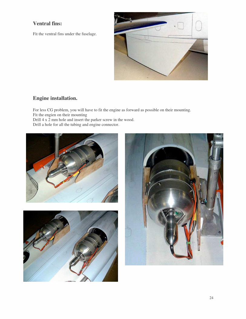
Ventral fins:
Fit the ventral fins under the fuselage.
Engine installation.
For less CG problem, you will have to fit the engine as forward as possible on their mounting.Fit the engien on their mountingDrill 4 x 2 mm hole and insert the parker screw in the wood.Drill a hole for all the tubing and engine connector.
25
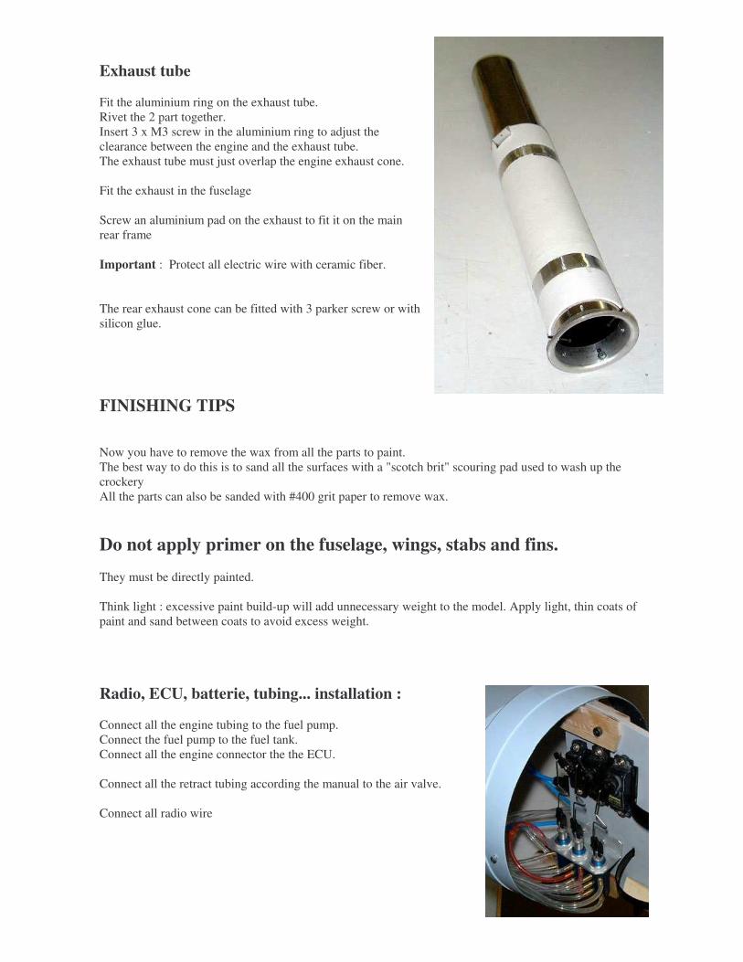
Exhaust tube
Fit the aluminium ring on the exhaust tube.Rivet the 2 part together.Insert 3 x M3 screw in the aluminium ring to adjust theclearance between the engine and the exhaust tube.The exhaust tube must just overlap the engine exhaust cone.
Fit the exhaust in the fuselage
Screw an aluminium pad on the exhaust to fit it on the mainrear frame
Important : Protect all electric wire with ceramic fiber.
The rear exhaust cone can be fitted with 3 parker screw or withsilicon glue.
FINISHING TIPS
Now you have to remove the wax from all the parts to paint.The best way to do this is to sand all the surfaces with a "scotch brit" scouring pad used to wash up thecrockeryAll the parts can also be sanded with #400 grit paper to remove wax.
Do not apply primer on the fuselage, wings, stabs and fins.
They must be directly painted.
Think light : excessive paint build-up will add unnecessary weight to the model. Apply light, thin coats ofpaint and sand between coats to avoid excess weight.
Radio, ECU, batterie, tubing... installation :
Connect all the engine tubing to the fuel pump.Connect the fuel pump to the fuel tank.Connect all the engine connector the the ECU.
Connect all the retract tubing according the manual to the air valve.
Connect all radio wire

26
Fit the radio and ECU close to the cockpit
Fit the ECU batterie and radio batteries inthe nose (on the C33 frame)
Secure all the screw with threated lock.
RADIO
The Sukhoi 27 needs very good servos :
For the 2 tailerons, we recommend to use 4 very good servos with metallic gears : 9 kg torque
NG steering : 1 servo 4 kg torqueRetract + gear doors + locking : 3 micro servos 1 kg torque
You normally need 2 x 1700 Mah batteries power to have a correct Center of Gravity. The correct CG isdrawn on the plan in attach.
Note : balance the model with the gear down and the fuel tanks empty.
You also need 1 electronic mixers on your radio.You must mix the 2 tailerons like a delta.
Taileron : in roll : 30 mm up and 30 mm down at the leading edgein pitch : 40 mm up and 40 mm down at the leading edge
With a Mercury engine or a RAM engine, the total weight of the Su 27 is 19 kg tanks empty
Important note : Pay very careful attention to structural integrity. This jet can reach speeds ofover 300 KPH. It is your responsibility to operate it safely.
Specifications may change without notice.