Embed Size (px)
Citation preview
Sriram Aaleti and Sri Sritharan 1
DESIGN OF UHPC WAFFLE DECK FOR ACCELERATED BRIDGE 1
CONSTRUCTION 2
3
Sriram Aaleti1 and Sri Sritharan
2 4
5 1
Assistant Professor, Department of Civil, Construction and Environmental Engineering,
University of Alabama, 2037C, SERC Building, Tuscaloosa, AL, 35487; Phone: 205-348-5110;
Fax: 205-348-0783; [email protected] (Corresponding Author)
2 Wilson Engineering Professor, Department of Civil, Construction, and Environmental
Engineering, Iowa State University, 376 Town Engineering Building, Ames, IA, 50011-3232;
Phone: 515-294-5238; Fax: 515 -294 -7424; [email protected]
6
7
8
Submission Date: August 1st, 2013 9
10
Words in Text: 4793 11
Number of Figures: 7 12
Number of Tables: 2 13
Total Word Count: 7043 14
15
TRB 2014 Annual Meeting Paper revised from original submittal.
Sriram Aaleti and Sri Sritharan 2
ABSTRACT 1
As a part of an innovation project funded by the Federal Highway Administration 2
(FHWA) Highways for LIFE program (HfL), a full-depth precast, ultra-high-performance 3
concrete (UHPC) waffle deck panel and appropriate connections suitable for field 4
implementation of waffle decks were developed. Following a successful full-scale validation test 5
on a unit consisting of two panels with three types of connections under laboratory conditions, 6
the waffle deck was installed successfully on a replacement bridge in Wapello County, Iowa. 7
The subsequent load testing confirmed the desirable performance of the UHPC waffle deck 8
bridge. Using the lessons from the completed project and outcomes from a series of simple and 9
detailed finite element analyses of waffle decks, a design guide was developed to help broaden 10
the design and installation of the UHPC waffle deck panel cost effectively in new and existing 11
bridges. This paper provides a summary of the waffle deck design introduced in the guide as it is 12
applicable new bridges. To minimize cost of this new bridge deck system, information on 13
maximum spacing of ribs and simplified connections, along with design of the deck panel for 14
positive and negative moments are presented. 15
16
TRB 2014 Annual Meeting Paper revised from original submittal.
Sriram Aaleti and Sri Sritharan 3
INTRODUCTION 1
The combination of aging infrastructure, increasing numbers of structurally deficient or 2
obsolete bridges, and increasing traffic volume in the US demands both rapid improvements to 3
the Nation’s bridge infrastructure and increase in bridge longevity. The increased emphasis on 4
work zone safety, user costs associated with traffic delays and environmental impacts of the 5
construction process, requires development of technologies and structural details suitable for 6
accelerated construction. In consideration of these challenges, the Federal Highway 7
Administration (FHWA) has been promoting Accelerated Bridge Construction (ABC) methods 8
using prefabricated bridge elements. 9
In the context of ABC, precast concrete deck panels are being increasingly utilized by 10
Departments of Transportation (DOT) in several states for both bridge deck replacements and 11
new structures to decrease construction time (1). Furthermore, the use of prefabricated full-depth 12
precast concrete deck systems can accelerate the construction and rehabilitation of bridge decks 13
significantly, while extending the service life and lower life-cycle costs of the bridge decks and 14
minimize the delays and disruptions to the community (2). However, transverse connections used 15
previously between precast bridge deck panels have exhibited various serviceability challenges 16
due to cracking and poor construction of connections (3). Therefore, it is imperative that durable 17
and efficient field connections be developed to implement precast deck panels successfully in 18
practice. These connections can utilize high-performance materials such as ultra-high-19
performance concrete (UHPC) to ensure improved performance. While these materials may 20
adhere well to the precast components, it is important to design these connections to prevent 21
cracking and leakage along the connection interfaces between precast elements. 22
UHPC is a newly developed concrete material that exhibits high compressive strength, 23
dependable tensile strength, and excellent durability properties including very low permeability. 24
The superior structural characteristics and durability of UHPC are perceived to provide major 25
improvements over ordinary concrete and high-performance concrete (HPC) bridges in terms of 26
long-term structural efficiency, durability, and possibly cost-effectiveness. Hence, the 27
construction of new bridges and renewal of aging highway bridges using UHPC has been 28
explored in terms of improving construction efficiency, enhancing bridge performance, and 29
reducing maintenance and life-cycle costs. Previous use of UHPC for bridge applications (mostly 30
in bridge girders) in the US has proven to be efficient and successful (4, 5, 6, and 7). 31
A prefabricated UHPC waffle deck system with field-cast UHPC connections was 32
developed as part the FHWA Highways for LIFE (HfL) program by combining the advantages of 33
UHPC with those of precast deck systems. An integrated experimental and analytical study was 34
performed to evaluate the performance of the precast UHPC waffle deck system and UHPC 35
connections under laboratory (8) and field conditions (9). The UHPC waffle deck system 36
performed extremely well under service, ultimate and fatigue loading, with the latter two tests 37
completed under the laboratory conditions. The ultimate capacity tests revealed that the UHPC 38
waffle deck system had significantly higher capacity than the required design level capacity (10), 39
suggesting potential improvements to the design of the UHPC waffle deck system and reduction 40
in the construction costs. 41
Given the success of the precast UHPC waffle deck system and increased interest in full-42
depth precast deck panels for ABC, a design guide was developed to increase the awareness, 43
improve efficiency, and broaden the use of UHPC waffle deck systems for new and replacement 44
bridges. This guide provides the technical and practical information necessary to allow future 45
bridge owners to consider the use of UHPC waffle slabs in a wide variety of bridge types. This 46
TRB 2014 Annual Meeting Paper revised from original submittal.
Sriram Aaleti and Sri Sritharan 4
paper focuses on the recommendations developed for the design of the waffle deck slab and a 1
suitable set of connections as applicable to new bridges. 2
3
ULTRA-HIGH PERFORMANCE CONCRETE 4
UHPC is an advanced, highly engineered, cementitious material consisting of typical 5
portland cement, fine aggregate made of sand, silica fume, crushed quartz, steel fibers, super 6
plasticizers, and high water reducers. A few notable differences in the UHPC composition when 7
compared to HPC are the lack of coarse aggregate, addition of steel fibers, high proportions of 8
cementitious materials, and low water/cement ratio. The use of powder and well-graded 9
constituents helps to achieve a high packing density for the UHPC, leading to significantly 10
improved mechanical properties such as increased compressive strength and considerable tensile 11
strength as compared to HPC and normal-strength concrete (NSC). The use of steel fibers in 12
UHPC improves the material’s ductility as well its tension capacity. Based on an extensive 13
literature review of UHPC research done in the U.S., recommendations for the material behavior 14
as applicable in the design of structures are presented in the design guide (11). 15
A selected set of recommendations, which are critical in the design of precast waffle deck 16
system, are presented below. 17
In precast environments, UHPC is commonly subjected to heat treatment at 194 °F at 95 18
percent humidity conditions to accelerate the full development of its strength and 19
durability properties. However, this is not a requirement. Ambient or air curing of 20
UHPC is also appropriate depending on the constraints set forth by the specific 21
application (e.g., field cast joints between deck panels) 22
The compression behavior of UHPC is linear upto a strain of 0.0032. The design 23
compressive strength of the UHPC can be taken as 24 ksi and 18 ksi for heat treated and 24
air-cured (ambient curing) conditions, respectively. 25
The tension behavior of UHPC can be represented with an elastic-perfectly plastic 26
curve. The design tension strength of the UHPC can be taken as 1.2 ksi. 27
The elastic modulus of UHPC can be approximated to √ . In the absence 28
of exact concrete strength, a modulus value of 7,500 ksi can be used for design purposes. 29
The unit weight of the UHPC is 157 lb/ft3. 30
The minimum concrete cover for unprotected mild steel reinforcement in UHPC shall be 31
0.75 inches because of excellent durability properties of UHPC. 32
33
UHPC WAFFLE DESK SYSTEM 34
Analogous to the typical full-depth precast deck systems currently used in practice and 35
developed in previous research (12), the waffle deck system consists of a series of UHPC waffle 36
deck panels that are full-depth in thickness (as required by the structural design) and connected 37
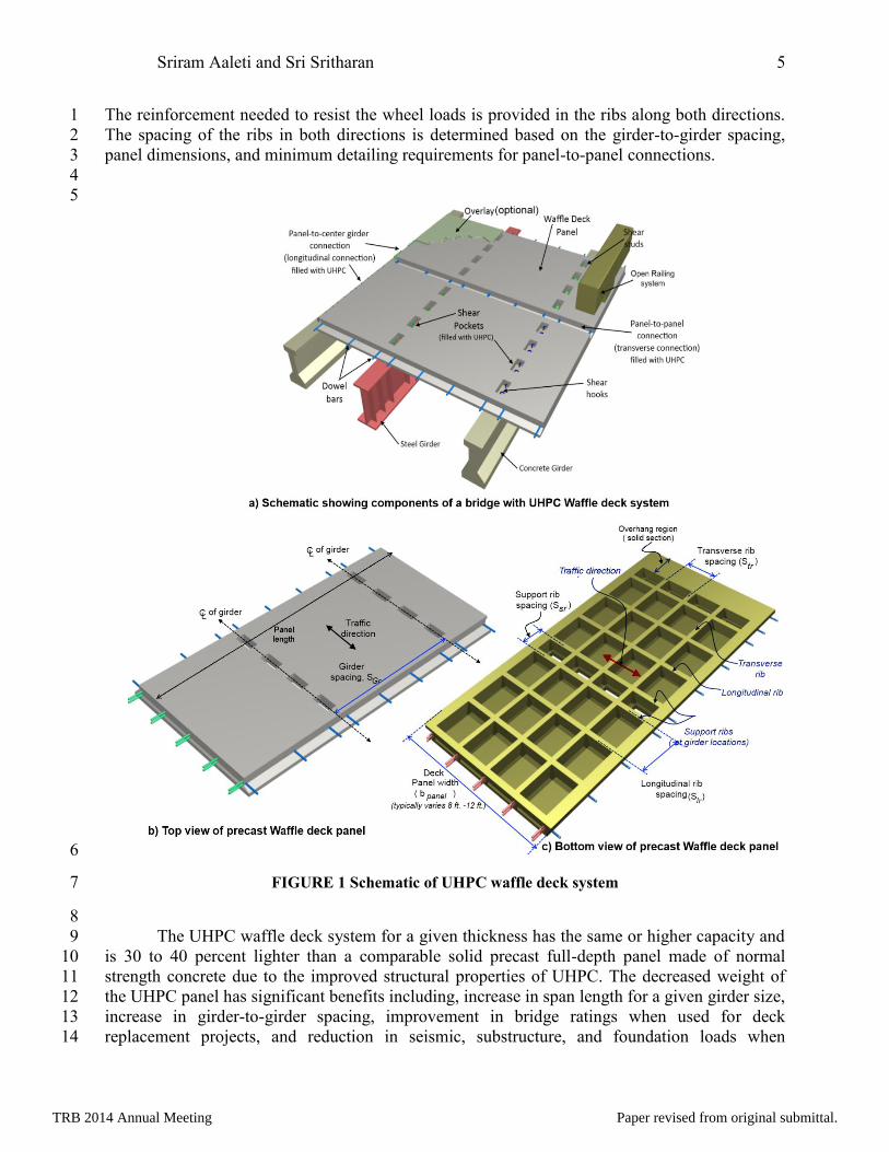
to the supporting girders with robust connections. A UHPC waffle deck panel consists of a thin 38
slab, cast integrally with concrete ribs spanning in the transverse and longitudinal directions. 39
This system is similar to the two-way joist system used by the building industry. The schematic 40
of the waffle deck system is shown in FIGURE 1. The transverse ribs along the deck panel acts 41
as T-beams, distributing wheel load effects to the adjacent bridge girders. The longitudinal ribs 42
help in distributing the wheel load to the adjacent panels through the panel-to-panel connections. 43
TRB 2014 Annual Meeting Paper revised from original submittal.
Sriram Aaleti and Sri Sritharan 5
The reinforcement needed to resist the wheel loads is provided in the ribs along both directions. 1
The spacing of the ribs in both directions is determined based on the girder-to-girder spacing, 2
panel dimensions, and minimum detailing requirements for panel-to-panel connections. 3
4
5
6
FIGURE 1 Schematic of UHPC waffle deck system 7
8
The UHPC waffle deck system for a given thickness has the same or higher capacity and 9
is 30 to 40 percent lighter than a comparable solid precast full-depth panel made of normal 10
strength concrete due to the improved structural properties of UHPC. The decreased weight of 11
the UHPC panel has significant benefits including, increase in span length for a given girder size, 12
increase in girder-to-girder spacing, improvement in bridge ratings when used for deck 13
replacement projects, and reduction in seismic, substructure, and foundation loads when 14
TRB 2014 Annual Meeting Paper revised from original submittal.
Sriram Aaleti and Sri Sritharan 6
compared to solid precast deck panel systems. The presence of the steel fibers in UHPC and very 1
minimal shrinkage of UHPC after steam curing of the precast elements also decreases the 2
reinforcement requirements when compared to traditional precast deck panels. 3
DESIGN OF WAFFLE DECK PANELS 4
The design of the waffle deck panels consist of two main steps: geometrical design and 5
structural design. In geometrical design, critical dimensions of the waffle deck panel are arrived 6
based primarily on the bridge functional requirements. The structural design phase consists of the 7
design of the primary deck reinforcement (both transverse and longitudinal) to resist the 8
AASHTO design loads. 9
Geometrical Design: 10
In this section, several recommendations to arrive at the dimensions of the UHPC waffle 11
deck panel are provided. 12
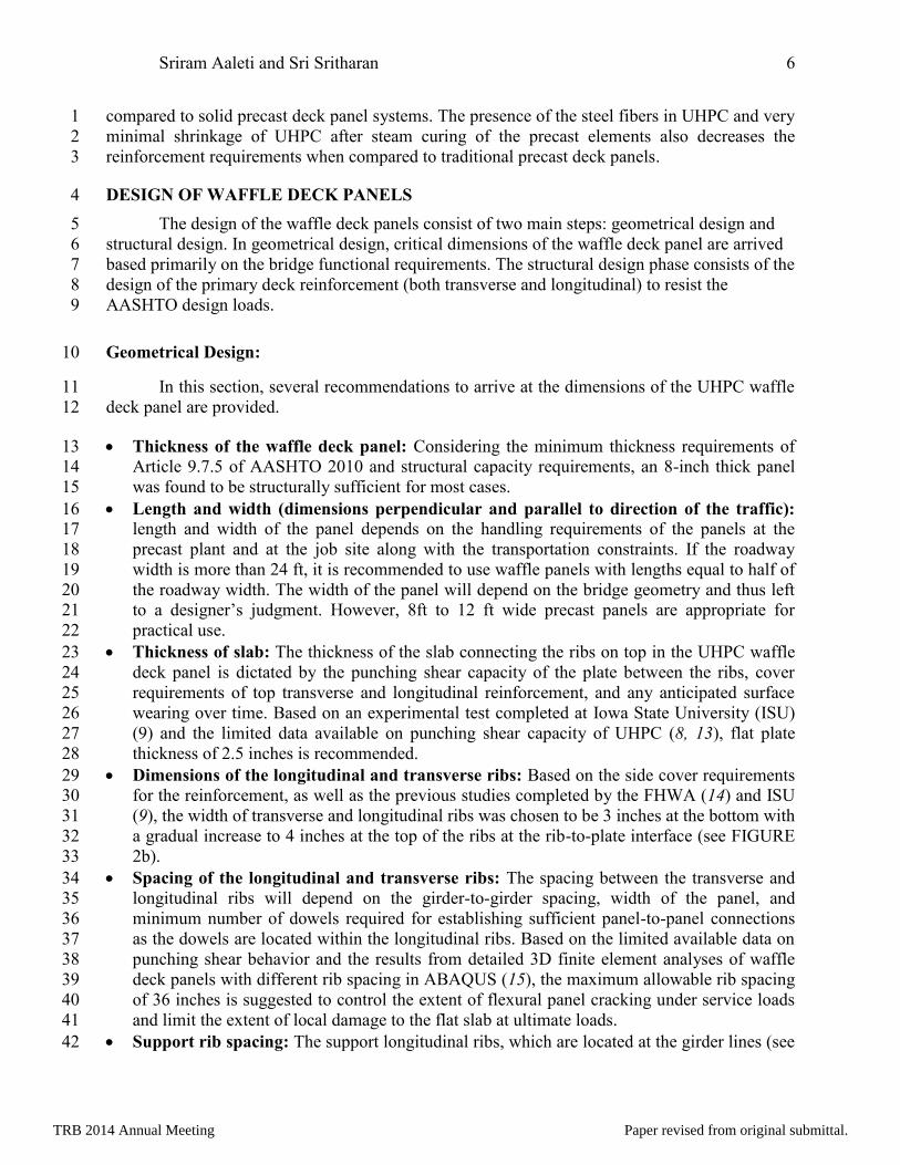
Thickness of the waffle deck panel: Considering the minimum thickness requirements of 13
Article 9.7.5 of AASHTO 2010 and structural capacity requirements, an 8-inch thick panel 14
was found to be structurally sufficient for most cases. 15
Length and width (dimensions perpendicular and parallel to direction of the traffic): 16 length and width of the panel depends on the handling requirements of the panels at the 17
precast plant and at the job site along with the transportation constraints. If the roadway 18
width is more than 24 ft, it is recommended to use waffle panels with lengths equal to half of 19
the roadway width. The width of the panel will depend on the bridge geometry and thus left 20
to a designer’s judgment. However, 8ft to 12 ft wide precast panels are appropriate for 21
practical use. 22
Thickness of slab: The thickness of the slab connecting the ribs on top in the UHPC waffle 23
deck panel is dictated by the punching shear capacity of the plate between the ribs, cover 24
requirements of top transverse and longitudinal reinforcement, and any anticipated surface 25
wearing over time. Based on an experimental test completed at Iowa State University (ISU) 26
(9) and the limited data available on punching shear capacity of UHPC (8, 13), flat plate 27
thickness of 2.5 inches is recommended. 28
Dimensions of the longitudinal and transverse ribs: Based on the side cover requirements 29
for the reinforcement, as well as the previous studies completed by the FHWA (14) and ISU 30
(9), the width of transverse and longitudinal ribs was chosen to be 3 inches at the bottom with 31
a gradual increase to 4 inches at the top of the ribs at the rib-to-plate interface (see FIGURE 32
2b). 33
Spacing of the longitudinal and transverse ribs: The spacing between the transverse and 34
longitudinal ribs will depend on the girder-to-girder spacing, width of the panel, and 35
minimum number of dowels required for establishing sufficient panel-to-panel connections 36
as the dowels are located within the longitudinal ribs. Based on the limited available data on 37
punching shear behavior and the results from detailed 3D finite element analyses of waffle 38
deck panels with different rib spacing in ABAQUS (15), the maximum allowable rib spacing 39
of 36 inches is suggested to control the extent of flexural panel cracking under service loads 40
and limit the extent of local damage to the flat slab at ultimate loads. 41
Support rib spacing: The support longitudinal ribs, which are located at the girder lines (see 42
TRB 2014 Annual Meeting Paper revised from original submittal.
Sriram Aaleti and Sri Sritharan 7
FIGURE 1b), provide an enclosure for the girder-to-panel connection, and is referred to as 1
the shear pocket connection, making the support rib spacing dependent on the top flange 2
width of the girder. It is recommended that the support rib spacing is limited to a value less 3
than the beam top flange width, with a minimum value of 12 inches (see FIGURE 2c). 4
Shear Pockets: Shear pockets facilitate the connection to achieve full composite action 5
between the precast waffle panels and supporting systems (concrete girders, steel girders, 6
stringers, etc.). If the shear studs/hooks are positioned uniformly along the girder length 7
(typical in concrete girder), the shear pocket spacing should be equal to the transverse rib 8
spacing. However, if a group configuration is used for the shear studs, the shear pockets can 9
be placed at spacing of 2 to 4 ft apart, in agreement with the maximum shear stud group 10
spacing allowed by the AASHTO guidelines (16) and the recent studies on shear stud group 11
spacing (17). 12
13
14
FIGURE 2 Recommended geometric dimensions for waffle deck panels 15
Flexural Design: 16
The experimental testing of waffle deck system at Iowa State University demonstrated 17
that the wheel load is distributed to the supporting girders in a similar fashion to the traditional 18
TRB 2014 Annual Meeting Paper revised from original submittal.
Sriram Aaleti and Sri Sritharan 8
cast-in-place deck system (9). The extent of distribution of the wheel load among the transverse 1
ribs of the waffle panel is dependent on the rib spacing and girder spacing. Therefore, the waffle 2
deck panel system can be designed conservatively using the strip method as described by the 3
current AASHTO LRFD specifications (16). The transverse strip, whose width is estimated 4
according to the Article 4.6.2.1.3 in the AASHTO specifications (16), is analyzed as a 5
continuous beam supported by bridge girders, which are assumed to be considered as non-6
settling rigid supports. The transverse strip width depends on the location of the critical section 7
along the length of the panel for in the +ve moment (+M), -ve moment (-M) or overhang regions. 8
The transverse strip width for the waffle deck system can be arrived using AASHTO 9
specifications and is given by Eq.(1);. The entire transverse strip is designed to resist the dead 10
load and live load effects with appropriate load factors at different limit states. 11
ts
26 + 6.6 S (ft) for +ve moment
transverse strip width W (in.) 48 + 3.0 S (ft) for -ve moment
45 +10.0 X (ft) overhang
(1) 12
13
where S = girder-to-girder spacing in feet and X = distance of the critical location from 14
the centerline of exterior girder (in feet). 15
Design Loads 16
The design loads include the dead load due to self-weight of waffle panel and wearing 17
surface (if used), live load (design truck load) and collision loads. Design moments are 18
determined at three different regions along the panel cross-section including, section at the center 19
of span between the girders, sections over interior girders, and the overhang section. As detailed 20
in the AASHTO guidelines, the interior spans between girders are investigated for positive 21
bending at the strength-I limit state. Sections over interior girders are examined for negative 22
bending at the strength-I limit, while the overhang region is investigated for different 23
combinations of dead, live, and collision loads for the strength-I and extreme event II limit states. 24
The deck system should be also designed to satisfy the serviceability requirements as required by 25
the AASHTO 5.7.3.4 article. The previously established geometric details along with the 26
following design parameters are used while arriving at the loads on the deck panels. 27
The longitudinal and transverse rib spacing vary between 18 to 36 inches. 28
A girder centerline spacing of 4 to 10 ft, which was established based on an extensive review 29
of frequently used standard details used by several State DOTs including Alabama, Florida, 30
Georgia, Illinois, Indiana, Iowa, Kentucky, Nebraska, New Jersey, New York, Ohio, 31
Oklahoma, Virginia, and Wisconsin. 32
Dead Load 33
Dead load on the waffle panel includes the self-weight of the panel (DC) and the weight 34
of any future wearing surface or overlays (wws) (if used by the DOT). The self-weight of the 35
waffle deck panel will depend on the rib spacing and is given by Eq.(2). 36
TRB 2014 Annual Meeting Paper revised from original submittal.

Sriram Aaleti and Sri Sritharan 9
(in psf.) 112
uhpctr w wwaffle slab
lr tr
S b hw h
S S
(2) 1
where hslab = thickness of top slab in inches (= 2.5 in.), Str = transverse rib spacing in 2
inches, Slr = longitudinal rib spacing in inches, hw = rib height in inches (= hdeck – hslab) (= 8 in. - 3
2.5 in. = 5.5 in.), and uhpc = unit density of UHPC (= 157 pcf ). 4
The design dead load is given by following equation. 5
ts tsw =1.25 W 1.5 Wdead
u waffle wsw w (3) 6
Live Load 7
The precast deck panel is designed for HL-93 truck loading. More details of the HL-93 8
truck loading can be found in Section 3.6 of the AASHTO LRFD Bridge Design Specifications 9
(16). 10
Design moment 11
The moment demand for deck panel between the girders (+ve moment region) and at the 12
interior girder locations (-ve moment region) is estimated using the strength-I limit state. The 13
positive and negative moment demand due to the dead load can be estimated using Eq.(4). 14
2
whew
M = M = , re S = girder spacing10
.dead
DL DL uu u
S (4) 15
The positive and negative design moments due to the live load ( M and MLL LL
u u
) can be 16
arrived at using the AASHTO LRFD Bridge Design Specifications Table A4-1. The maximum 17
+ve and –ve moment demand varies from 8.29 kip-ft/ft to 13.17 kip-ft/ft and 3.81 kip-ft/ft to 18
13.41 kip-ft/ft respectively, with the girder spacing changing from 4 ft to 10 ft. Design moment 19
values for different girder spacing can be found in Aaleti et al. (11). 20
Flexural Capacity Calculation 21
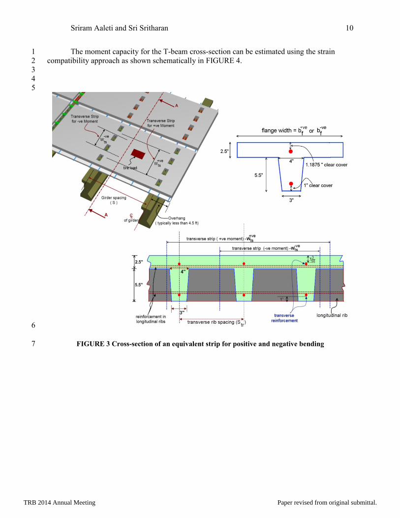
Moment capacity of the waffle deck panel in the positive and negative bending directions 22
can be estimated using a transverse strip along the deck panel (see FIGURE 3a). As shown in 23
FIGURE 3b, the equivalent strip width contains a number of ribs depending on the girder span 24
and rib spacing in the waffle deck panel. The cross-section of the transverse strip can be further 25
divided into a combination of T-beams with a cross-section, as shown in FIGURE 3c. The flange 26
width for positive bending (bf+ve
) or negative bending (bf-ve
) can be estimated using the Eq.(5). 27
+ve -ve
+ve -vets tsf f+ve -ve
ts ts
tr tr
W Wb = and b
W W1+interger value of 1+interger value of
S S
(5) 28
where Wts+ve
and Wts-ve
= equivalent strip width for positive moment and negative moment 29
regions, respectively. 30
TRB 2014 Annual Meeting Paper revised from original submittal.
Sriram Aaleti and Sri Sritharan 10
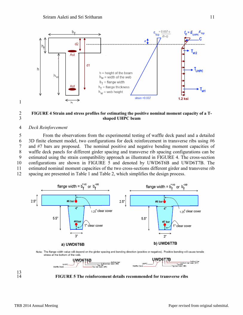
The moment capacity for the T-beam cross-section can be estimated using the strain 1
compatibility approach as shown schematically in FIGURE 4. 2
3
4
5
6
FIGURE 3 Cross-section of an equivalent strip for positive and negative bending 7
TRB 2014 Annual Meeting Paper revised from original submittal.
Sriram Aaleti and Sri Sritharan 11
1
FIGURE 4 Strain and stress profiles for estimating the positive nominal moment capacity of a T-2 shaped UHPC beam 3
Deck Reinforcement 4
From the observations from the experimental testing of waffle deck panel and a detailed 5
3D finite element model, two configurations for deck reinforcement in transverse ribs using #6 6
and #7 bars are proposed. The nominal positive and negative bending moment capacities of 7
waffle deck panels for different girder spacing and transverse rib spacing configurations can be 8
estimated using the strain compatibility approach as illustrated in FIGURE 4. The cross-section 9
configurations are shown in FIGURE 5 and denoted by UWD6T6B and UWD6T7B. The 10
estimated nominal moment capacities of the two cross-sections different girder and transverse rib 11
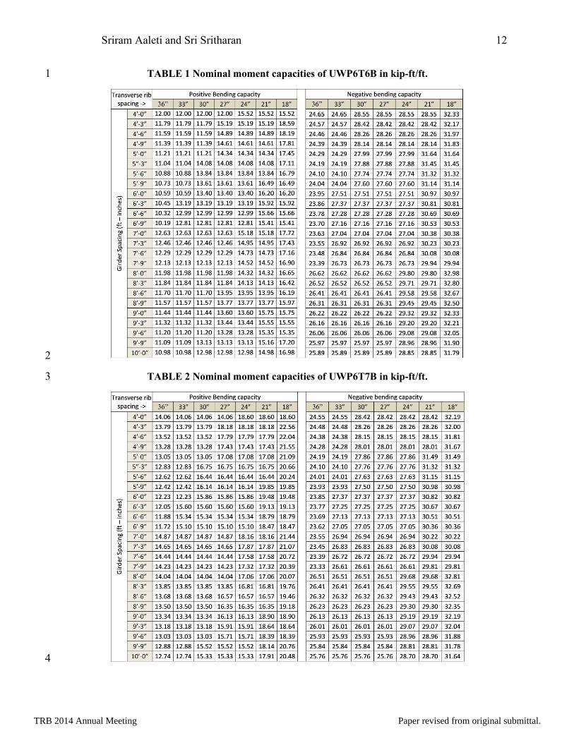
spacing are presented in Table 1 and Table 2, which simplifies the design process. 12
13 FIGURE 5 The reinforcement details recommended for transverse ribs 14
TRB 2014 Annual Meeting Paper revised from original submittal.
Sriram Aaleti and Sri Sritharan 12
TABLE 1 Nominal moment capacities of UWP6T6B in kip-ft/ft. 1
2
TABLE 2 Nominal moment capacities of UWP6T7B in kip-ft/ft. 3
4
TRB 2014 Annual Meeting Paper revised from original submittal.
Sriram Aaleti and Sri Sritharan 13
Overhang Design 1
The overhang region is designed for different combinations of dead, live, and collision 2
loads for the Strength I and Extreme Event II limit states as required by AASHTO guidelines 3
(16). An F-shape standard concrete railing is used for designing the overhang region for collision 4
loads. In addition, based on the suggestions from Iowa DOT designers, it is recommended to use 5
a solid cross-section for the overhang region instead of a waffle configuration. The solid section 6
for the overhang will not only help in addressing the variability in the types of railings and their 7
capacities as used by DOTs, but also provide adequate space to include the necessary details for 8
attaching the railing to the precast deck. The negative moment capacity of the solid overhang for 9
the UWP6B6T and UWP6T7B configurations was found to vary between 37.6 kip-ft/ft to 41.83 10
kip-ft/ft depending on the transverse rib spacing. 11
Connection Details 12
The short-term and long-term performance and durability of bridges constructed using 13
these deck panels will be influenced by the quality of the connections among the panels (i.e., 14
panel-to-panel connections in both longitudinal and transverse directions) and with panels to 15
girders. Panel-to-panel connections are subjected to bending moments and vertical shear forces 16
under vehicular loading. In recent decades, a wide variety of deck level connection designs have 17
been deployed in bridge projects involving full-depth precast panels with substantial variance in 18
observed performance under traffic loads. Several of these connection details are provided in the 19
design guide (11). The connections that perform well typically consist of match-cast shear keys 20
with epoxy adhesive or grouted female-to-female joints with discrete reinforcement, combined 21
with field-cast concrete or grouted together with quality construction. A few connection details 22
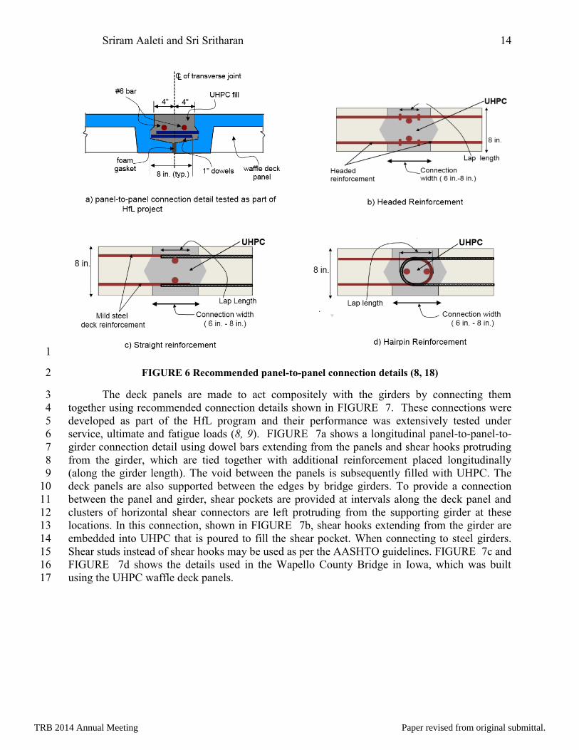
that are appropriate for the waffle deck panel-to-panel connection are shown in FIGURE 6. By 23
realizing the superior durability and bond characteristics of UHPC, all the connection regions are 24
designed with field casting of UHPC. The connection details presented in Figures 6 b, c and d 25
were developed for solid deck panels. However, these connections can be adopted for waffle 26
deck panels by making the cells adjacent to the connections to be solid. 27
28
TRB 2014 Annual Meeting Paper revised from original submittal.
Sriram Aaleti and Sri Sritharan 14
1
FIGURE 6 Recommended panel-to-panel connection details (8, 18) 2
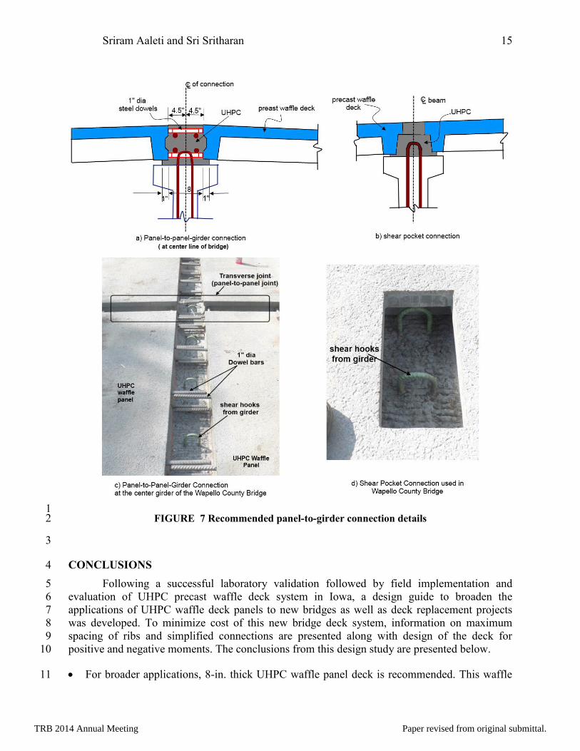
The deck panels are made to act compositely with the girders by connecting them 3
together using recommended connection details shown in FIGURE 7. These connections were 4
developed as part of the HfL program and their performance was extensively tested under 5
service, ultimate and fatigue loads (8, 9). FIGURE 7a shows a longitudinal panel-to-panel-to-6
girder connection detail using dowel bars extending from the panels and shear hooks protruding 7
from the girder, which are tied together with additional reinforcement placed longitudinally 8
(along the girder length). The void between the panels is subsequently filled with UHPC. The 9
deck panels are also supported between the edges by bridge girders. To provide a connection 10
between the panel and girder, shear pockets are provided at intervals along the deck panel and 11
clusters of horizontal shear connectors are left protruding from the supporting girder at these 12
locations. In this connection, shown in FIGURE 7b, shear hooks extending from the girder are 13
embedded into UHPC that is poured to fill the shear pocket. When connecting to steel girders. 14
Shear studs instead of shear hooks may be used as per the AASHTO guidelines. FIGURE 7c and 15
FIGURE 7d shows the details used in the Wapello County Bridge in Iowa, which was built 16
using the UHPC waffle deck panels. 17
TRB 2014 Annual Meeting Paper revised from original submittal.
Sriram Aaleti and Sri Sritharan 15
1 FIGURE 7 Recommended panel-to-girder connection details 2
3
CONCLUSIONS 4
Following a successful laboratory validation followed by field implementation and 5
evaluation of UHPC precast waffle deck system in Iowa, a design guide to broaden the 6
applications of UHPC waffle deck panels to new bridges as well as deck replacement projects 7
was developed. To minimize cost of this new bridge deck system, information on maximum 8
spacing of ribs and simplified connections are presented along with design of the deck for 9
positive and negative moments. The conclusions from this design study are presented below. 10
For broader applications, 8-in. thick UHPC waffle panel deck is recommended. This waffle 11
TRB 2014 Annual Meeting Paper revised from original submittal.
Sriram Aaleti and Sri Sritharan 16
deck is to have the ribs in both directions with recommended rib spacing of 18 to 36 inches. 1
Two different configurations for transverse rib reinforcement, which are applicable for 2
different girder spacing, are proposed (see FIGURE 5). The first configuration (UWD6T6B) 3
consists of #6 bars at the top and bottom of the transverse rib. The alternate configuration 4
(UWD6T7B) consists of a #7 bar at the bottom and a #6 bar at the top of the transverse rib. 5
In both configurations, #6 bars are provided in the longitudinal ribs at top and bottom. 6
The UWD6T6B configuration can be used for waffle deck panels with any rib configuration 7
(rib spacing < 36 inches) in bridges with a maximum girder spacing of 8.25 ft. This 8
configuration can be used for bridges with a girder spacing of 8.5 to 10 ft if the transverse rib 9
spacing is limited to 21 inches. 10
The UWD6T7B configuration can be used for waffle deck panels with variable transverse 11
and longitudinal rib spacing in bridges with a maximum girder spacing of 9.25 ft. For girder 12
spacing of 9.5 to 10 ft, the transverse rib spacing is limited to 30 inches. 13
To establish robust connection between waffle deck panels and girders, three different 14
connections including their details are presented. Their adequate performance under variety 15
of loads has been already verified. 16
ACKNOWLEDGEMENTS 17
The authors would like to thank the Federal Highway Administration (FHWA) Highways 18
for LIFE (HfL) program. Special thanks are given to Julie Zirlin, HfL Technology Partnerships 19
coordinator, for her advice and suggestions, and Ahmad Abu-Hawash, chief structural engineer 20
with the Iowa DOT Office of Bridges and Structures for his coordination and valuable input. In 21
addition, valuable feedback was received during the design guide development process from a 22
number of people, including Benjamin Graybeal with the FHWA Turner-Fairbank Highway 23
Research Center, Dean Bierwagen, Kenneth Dunker, Ping Lu, and Michael Nop with the Iowa 24
DOT, Mathew Royce with the New York State DOT, Bruce Johnson with the Oregon DOT, 25
Claude Napier with the Virginia DOT, and Brian Moore with Wapello County, Iowa. 26
REFERENCES 27
1. Issa, M. A., Yousif, A. A., and Issa, M. A. “Experimental Behavior of Full-Depth Precast 28
Concrete Panels for Bridge Rehabilitation.” ACI Structural Journal. V. 97, No. 3, May-29
June 2000. pp. 397-407. 30
2. Berger, R. H. “Full-Depth Modular Precast Prestressed Bridge Decks.” Bridges and 31
Culverts. Transportation Research Record: Journal of the Transportation Research Board. 32
No. 903. Transportation Research Board of the National Academies. Washington, DC. 33
1983. pp. 52-59. 34
3. Issa, M. A., Cyro do V., Abdalla, H., Islam, M. S., and Issa, M. A. “Performance of 35
Transverse Joint Grout Materials in Full-Depth Precast Concrete Bridge Deck Systems,” 36
Precast/Prestressed Concrete Institute (PCI) Journal. V. 48, no. 4, July-August 2003. pp. 37
92-103. 38
4. Bierwagen, D., and Abu-Hawash, A. “Ultra-High Performance Concrete Highway 39
Bridge.” Proceedings of the 2005 Mid-Continent Transportation Research Symposium, 40
Ames, Iowa. 2005. pp.1-14. 41
TRB 2014 Annual Meeting Paper revised from original submittal.
Sriram Aaleti and Sri Sritharan 17
5. Keierleber, B., Bierwagen, D., Wipf, T., and Abu-Hawash, A. “Design of Buchanan 1
County, Iowa Bridge Using Ultra-High Performance Concrete and Pi-Girder Cross 2
Section.” Proceedings of the Precast/Prestressed Concrete Institute National Bridge 3
Conference, Orlando, FL. 2008. 4
6. Wipf, T. J., Phares, B. M., Sritharan, S., Degen, E. B., and Giesmann, T. M. Design and 5
Evaluation of a Single-Span Bridge Using Ultra-High Performance Concrete. IHRB 6
Project TR-529. Iowa State University, Ames, IA. September 2009. 7
7. Rouse, J. M., Wipf, T. J., Phares, B., Fanous, F., and Berg, O Design, Construction, and 8
Field Testing of an Ultra High Performance Concrete Pi-Girder Bridge. IHRB Project 9
TR-754. Iowa State University, Ames, IA. January 2011. 10
8. Aaleti, S., Sritharan, S., Bierwagen, D., and Wipf, T., J. (2011 a) “Structural Behavior of 11
Waffle Bridge Deck Panels and Connections of Precast Ultra-High-Performance 12
Concrete: Experimental Evaluation.” Transportation Research Record: Journal of the 13
Transportation Research Board. No. 2251. Transportation Research Board of the National 14
Academies, Washington, DC. 2011. pp. 82-92. 15
9. Aaleti, S., Sritharan, S., Bierwagen, D., and Moore, P., B.(2011 b) “Precast UHPC 16
Waffle Deck Panels And Connections For Accelerated Bridge Construction” 2011 PCI 17
National Bridge Conference, Salt Lake City, Utah, October 22-26, 2011 18
10. Rouse, M., Honarvar, E., Aaleti, S., Sritharan, S., and Wipf, T. Phase 2: The Structural 19
Characterization of UHPC Waffle Bridge Deck Panels and Connections. IHRB Project 20
TR-614 Report. Iowa State University, Ames, IA. 2012. 21
11. Aaleti, S., Peterson, B., and Sritharan, S., (2013). Design Guide for Precast UHPC Waffle 22
Deck Panel System, including Connections, Report No. FHWA-HIF-13-032, Federal 23
Highway Administration, Washington, DC., June 2013 24
12. Badie, S. S., and M. K. Tadros. 2008. Full-Depth Precast Concrete Bridge Deck Panel 25
Systems. NCHRP Report 584. National Cooperative Highway Research Program. 26
Transportation Research Board of the National Academies. Washington, DC. 2008. 27
13. Harris, D. K., and C. L. Roberts-Wollmann. 2005. Characterization of The Punching 28
Shear Capacity Of Thin Ultra-High Performance Concrete Slabs. VTRC 05-CR26 final 29
report, Virginia Department of Transportation. 2005. 30
14. Graybeal, B. Analysis of an Ultra-High Performance Concrete Two-Way Ribbed Bridge 31
Deck Slab. TECHBRIEF, FHWA-HRT-07-055. Federal Highway Administration. 32
McLean, VA. 2007. 33
15. ABAQUS user's manual version 6.11, Dassault Systèmes Simulia Corp., 2012 34
16. American Association of State Highway and Transportation Officials (AASHTO). 35
AASHTO LRFD Bridge Design Specifications, 6th edition, Washington, DC. 2010. 36
17. Badie, S. S., Morgan Girgis, A., Tadros, M., and Nguyen, N. “Relaxing the Stud Spacing 37
Limit for Full-Depth Precast Concrete Deck Panels Supported on Steel Girders (Phase 38
I).” Journal of Bridge Engineering. 15.5. 2010. pp. 482-492. 39
18. Graybeal, B. Behavior of Field-Cast Ultra-High Performance Concrete Bridge Deck 40
Connections under Cyclic and Static Structural Loading. FHWA-HRT-11-023, Office of 41
Infrastructure Research & Development, Federal Highway Administration. McLean, VA. 42
2011 43
TRB 2014 Annual Meeting Paper revised from original submittal.