Embed Size (px)
Citation preview
Journal of Mechanical Science and Technology 25 (2) (2011) 415~427
www.springerlink.com/content/1738-494x
DOI 10.1007/s12206-010-1225-3
Disc cutters’ layout design of the full-face rock tunnel boring machine (TBM)
using a cooperative coevolutionary algorithm†
Wei Sun1 , Junzhou Huo1,*, Jing Chen2, Zhen Li1, Xu Zhang1, Li Guo
1,
Haifeng Zhao3 and Yu Zhao3 1School of Mechanical Engineering, Dalian University of Technology, Dalian 116024, P.R. China
2School of Naval Architecture Engineering, Dalian University of Technology, Dalian 116024, P.R. China 3Northern Heavy Shenyang Heavy Machinery Group Co., Ltd., Shenyang 110025, P.R. China
(Manuscript Received December 10, 2009; Revised July 21, 2010; Accepted November 3, 2010)
----------------------------------------------------------------------------------------------------------------------------------------------------------------------------------------------------------------------------------------------------------------------------------------------
Abstract
In rock TBM design the disc cutters’ layout design of the full-face rock tunnel boring machine (TBM) is one of the key technologies.
However, there are few published papers in literatures for various reasons. In this paper, based on the engineering technical requirements
and the corresponding cutter head’s structure design requirements, a nonlinear multi-objective disc cutters’ layout mathematical model
with complex constraints and the corresponding multi-stage solution strategy are presented, in which the whole disc cutters’ layout de-
sign process is decomposed into the disc cutters’ spacing design and the disc cutters’ plane layout design. A numerical simulation method
based on the FEM theory is adopted to simulate the rock chipping process induced by three TBM disc cutters to determine the optimal
cutter spacing. And a cooperative coevolutionary genetic algorithm (CCGA) is adopted to solve the disc cutters’ plane layout design
problem. Finally, a disc cutters’ layout design instance of the TBM is presented to demonstrate the feasibility and effectiveness of the
proposed method. The computational results show that the proposed method can be used to solve the disc cutters’ layout design problem
of the TBM and provide various layout schemes within short running times for the engineers to choose from.
Keywords: Full-face tunnel boring machine; Disc cutters’ layout; Coevolutionary algorithm; Spacing
----------------------------------------------------------------------------------------------------------------------------------------------------------------------------------------------------------------------------------------------------------------------------------------------
1. Introduction
The full face rock tunnel boring machine (TBM) is a large
and special engineering machine for tunnel boring that has
been widely applied to subway projects, railway projects,
highway projects and water-electricity projects. It is a very
high cost machine. Disc cutters’ layout design of the TBM is
one of the key technologies to improve the global perform-
ance of a TBM [1], and it directly affects the boring perform-
ance, the service life, the main bearing of the cutter head, the
vibration and the noise of the TBM. The main difficulties of
disc cutters’ layout design of the TBM lie in the combina-
tional explosion of computational complexity, the engineering
complexity, and the pragmatic approaches of engineering
practices, and belongs to a multi-objective optimization prob-
lem with nonlinear constraints.
Disc cutters’ layout design of the full face rock TBM is
closely related to the theory of cutter’s penetration into rocks,
the cutting force models and the performance prediction mod-
els. The theory of cutter’s penetration into rocks is a basis of
the cutting force models and the performance prediction mod-
els. It is often used to analyze the cutter head’s force distribu-
tion during the disc cutters’ layout design. It is crucial in un-
derstanding the stress fields and the resultant fractures that are
created beneath the penetrating edge of the disc cutter. In this
analysis, three previous theories derived from wedge indenta-
tion into rocks are used as a guide: shearing crushing theory,
the radial tension cracks crossing theory and the hybrid crush-
ing theory. These theories can be used to study the occurrence
of a highly stressed and crushed zone and the radial tension
cracks during a cutter’s penetration into rocks.
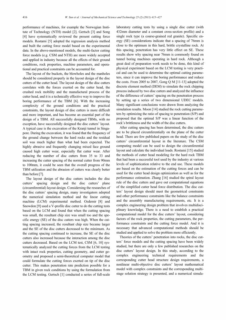
Three cutting forces are exerted on the tip of the disc cutter
during excavation: the normal force, the rolling force and the
side force. Many investigators have studied the cutting force
models that can be used to calculate the the normal force and
the rolling force. These models can be divided into two
categories: the semi-theoretical model, based on tests and the
theoretical analysis of the linear cutting machine (LCM), for
example the Colorado School of Mines (CSM) model [1]; and
the empirical model, which is based on the historical field
† This paper was recommended for publication in revised form by Associate Editor
In-Ha Sung *Corresponding author. Tel.: +86 411 84707435, Fax.: +86 411 84708812
E-mail address: [email protected]
© KSME & Springer 2011
416 W. Sun et al. / Journal of Mechanical Science and Technology 25 (2) (2011) 415~427
performance of machines, for example the Norwegian Insti-
tute of Technology (NTH) model [2]. Gertsch [3] and Song
[4] have systematically reviewed the present cutting force
models. Rostami [5] adopted the regression analysis method
and built the cutting force model based on the experimental
data. In the above-mentioned models, the multi-factor cutting
force models (e.g. CSM and NTH) are more widely accepted
and applied in industry because all the effects of their ground
conditions, rock properties, machine parameters, and opera-
tional and practical constraints can be accounted for.
The layout of the buckets, the blowholes and the manholes
should be considered properly in the layout design of the disc
cutters of the cutter head. The layout design of the disc cutters
correlates with the forces exerted on the cutter head, the
crushed rock mobility and the manufactural process of the
cutter head, and it is a technically effective way to improve the
boring performance of the TBM [6]. With the increasing
complexity of the ground conditions and the practical
constraints, the layout design of disc cutters is more difficult
and more important, and has become an essential part of the
design of a TBM. All successfully designed TBMs, with no
exception, have successfully designed the disc cutters’ layout.
A typical case is the excavation of the Kranji tunnel in Singa-
pore. During the excavation, it was found that the frequency of
the ground change between the hard rocks and the residual
soil was much higher than what had been expected. The
highly abrasive and frequently changing mixed face ground
caused high cutter wear, especially flat cutter wear. After
reducing the number of disc cutters from 35 to 33 and
increasing the cutter spacing of the normal cutter from 90mm
to 100mm, it could be seen that the overall progress of the
TBM utilization and the abrasion of cutters was clearly better
than before [7].
The layout design of the disc cutters includes the disc
cutters’ spacing design and the disc cutters’ plane
(circumferential) layout design. Considersing the researches of
the disc cutters’ spacing design, many investigators adopted
the numerical simulation method and the linear cutting
machine (LCM) experimental method. Ozdemir [8] and
Snowdon [9] used a V-profile disc cutter to do the cutting tests
based on the LCM and found that when the cutting spacing
was small, the resultant chip size was small too and the spe-
cific energy (SE) of the disc cutters was high. When the cut-
ting spacing increased, the resultant chip size became larger
and the SE of the disc cutters decreased to the minimum. As
the cutting spacing continued to increase, the SE of the disc
cutters also increased because the interaction among the disc
cutters decreased. Based on the LCM test, CSM [6, 10] sys-
tematically analyzed the cutting forces from the LCM testing
with intact rock properties, cutting geometry, and cutter ge-
ometry and proposed a semi-theoretical computer model that
could formulate the cutting forces exerted on tip of the disc
cutter. This makes penetration rate prediction possible for a
TBM in given rock conditions by using the formulation from
the LCM testing. Gertsch [1] conducted a series of full-scale
laboratory cutting tests by using a single disc cutter (with
432mm diameter and a constant cross-section profile) and a
single rock type (a coarse-grained red granite). Specific en-
ergy (SE) considerations indicate that a spacing of 76mm is
close to the optimum in this hard, brittle crystalline rock. At
this spacing, penetration has very little effect on SE. These
results show why spacing near 76mm is commonly found on
tunnel boring machines operating in hard rock. Although a
great deal of preparation work needs to be done, this kind of
physical experiment based on the LCM testing is very practi-
cal and can be used to determine the optimal cutting parame-
ters, since it can improve the boring performance and reduce
the costs. From 2005 to 2007, Gong Q M [11-13] adopted the
discrete element method (DEM) to simulate the rock chipping
process induced by two disc cutters and analyzed the influence
of the difference of cutters’ spacing on the penetration process
by setting up a series of two dimensional UDEC models.
Many significant conclusions were drawn from analyzing the
simulation results. Moon [14] studied the rock cutting parame-
ters by optimizing the ratio of spacing to penetration (S/P) and
proposed that the optimal S/P was a linear function of the
rock’s brittleness and the width of the disc cutters.
After cutting spacing has been determined, the disc cutters
are to be placed circumferentially on the plane of the cutter
head. There are few published papers on the study of the disc
cutters’ circumferential layout in the literature. The CSM
computing model can be used to design the circumferential
layout and calculate the individual loads. Rostami [15] studied
the methods of cutter head modeling for the hard rock TBM
that had been a successful tool used by the industry at various
levels of sophistication relative to the end use. These models
are based on the estimation of the cutting forces and can be
used for the cutter head design optimization as well as for the
performance estimation. Zhang [16] studied the spiral layout
rule of the disc cutters and gave out computational equations
of the simplified cutter head force distribution. The disc cut-
ters’ layout design should meet the geometrical constraints
and other performance constraints like the balance constraints
and the assembly manufacturing requirements, etc. It is a
complex engineering design problem that involves multidisci-
plinary knowledge. There is a need to establish a practical
computational model for the disc cutters’ layout, considering
factors of the rock properties, the cutting parameters, the per-
formance constraints and the cutting force model. And it is
necessary that advanced computational methods should be
studied and applied to solve the problem more efficiently.
Theories of the cutters’ penetration into rocks, the disc cut-
ters’ force models and the cutting spacing have been widely
studied, but there are only a few published researches on the
disc cutters’ layout design. In this study, according to the
complex engineering technical requirements and the
corresponding cutter head structure design requirements, a
nonlinear multi-objective disc cutters’ layout mathematical
model with complex constraints and the corresponding multi-
stage solution strategy is presented, and a numerical simula-
W. Sun et al. / Journal of Mechanical Science and Technology 25 (2) (2011) 415~427 417
tion method and a cooperative coevolutionary algorithm are
utilized to solve the disc cutters’ layout design problem.
Finally, using the above-metioned proposed method, an
instance of the disc cutters’ layout design of a TBM is
presented.
2. Problem statement
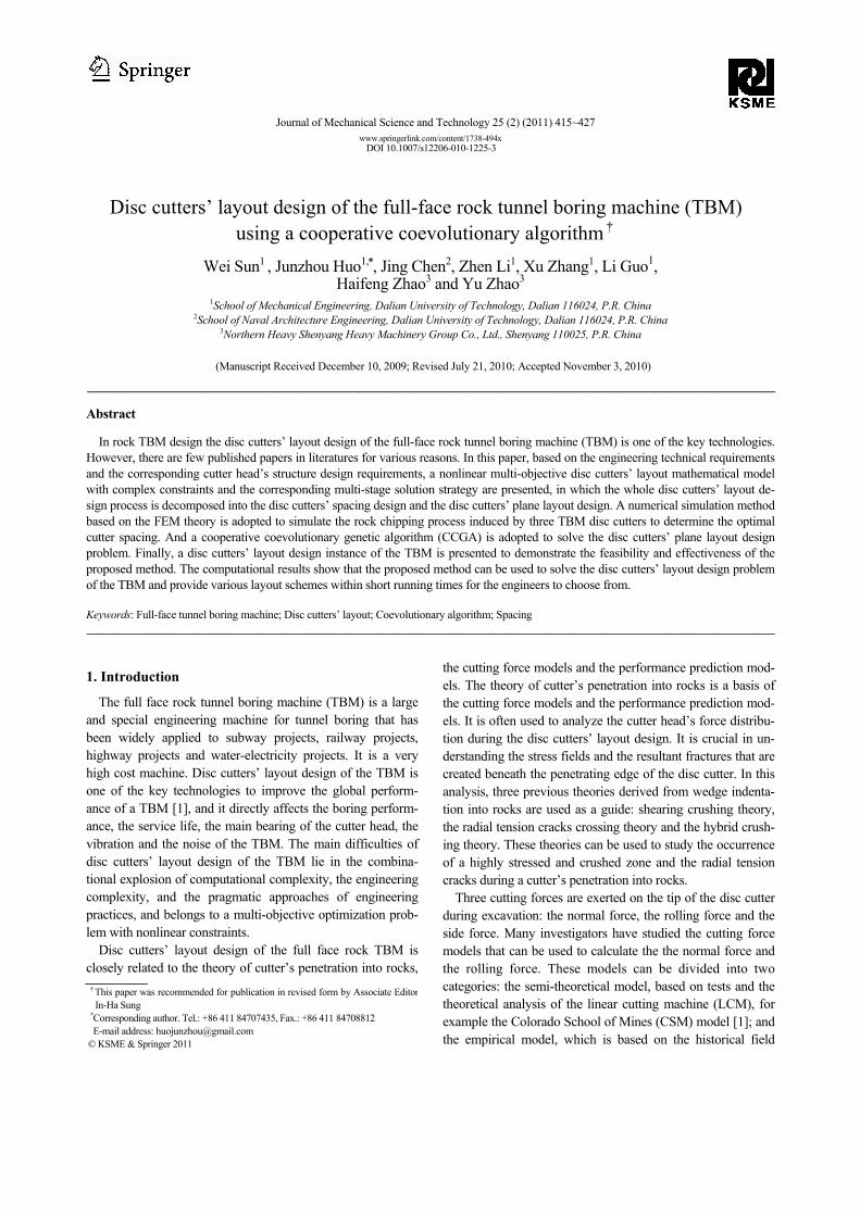
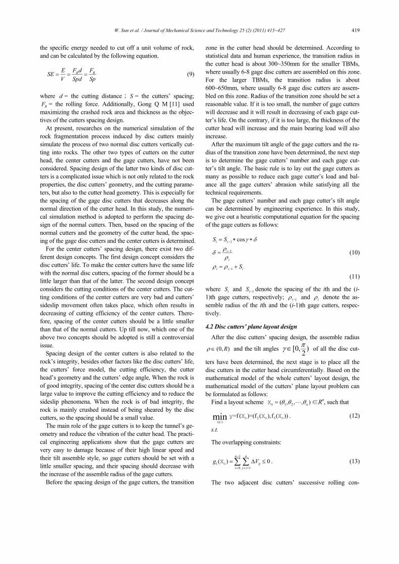
As shown in Fig. 1 and Fig. 2, the discs are so arranged that
they contact the entire cutting face in the concentric tracks
when the cutter head turns. The distance of the cutting tracks
and the discs are chosen depending on the rock type and the
difficult level of cutting. The sizes of the broken pieces of the
rock result from this. The rotating cutter head presses the discs
with high pressure against the rock face. The discs therefore
make a slicing movement across the rock face. The pressure at
the cutting edge of the disc cutters exceeds the compressive
strength of the rock and locally grinds it. So the cutting edge
of the disc pushes the rolling into the rock, until the advance
force and the hardness of the rock are in balance. Through this
displacement, described as net penetration, the cutter disc
creates a high stress locally, which leads to long flat pieces of
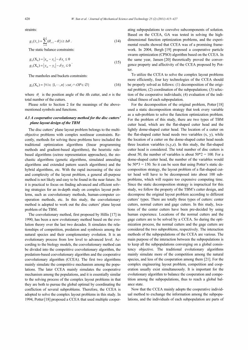
rock (chips) breaking off. The cutting forces on a disc cutter
mainly contain the normal force, the rolling force and the side
force. Fig. 2 illustrates these three cutting forces that are ex-
erted on the tip of the disc cutter during excavation. According
to the related literature [12, 15] and the practical engineers’
experiences, the technical requirements of disc cutters’ layout
design can be summarized as follows [23]:
① The amount of the eccentric forces of the whole system
is expected to be as small as possible;
② The amount of the eccentric moments of the whole sys-
tem is expected to be as small as possible;
③ The spacing of the disc cutters needs to be optimized,
which means that the specific energy needed to cut off unit
volume of rock is expected to be as small as possible;
④ Two adjacent disc cutters should crush the rock succes-
sively to maintain high cutting efficiency;
⑤ All the disc cutters should be contained within the cutter
head, with no overlapping among the disc cutters;
⑥ The position error of the centroid of the whole system
should not exceed an allowable value, and the smaller the
better;
⑦ All the disc cutters should not interfere with manholes
and buckets, respectively.
3. Mathematical model
Suppose that the set of disc cutters to be located on the cut-
ter head with radius equals to R is CUTs = {Cut1, Cut2,…,
Cutn},where n = total number of cutters. As shown in Fig. 1,
all the disc cutters are simplified as circles in this study and
are regarded as rigid bodies with uniform mass distribution.
So the ith cutter can be denoted as ( ),i i iCut p , r where
3( )Ti i i ip = r , , Rρ θ ∈ is the position of a reference point (the
centroid of the object) of Cuti in the coordinate system oxyz;
(0, )i Rρ ∈ is the radius of the ith cutter from the center of the
cutter head; [0,2 )iθ π∈ is the position angle of the ith cutter;
[0, )2
i
πγ ∈ is the tilt angle of the ith cutter; ir is the radius of
the ith cutter. Generally, the tilt angles of the normal cutters
are all zero. The masses and dimensions of all the disc cutters
are given in advance, so ip pi is the variable to be manipu-
lated in the following procedure. Thus, a general disc cutters’
layout scheme of a cutter head can be formulated as:
1 2 i i iX { , , , , , }, { , , }i n ix x x x x ρ θ γ= =L L . (1)
Then based on the technical requirements of the disc cut-
ters’ layout design, the mathematical model [23] of the whole
disc cutters’ layout problem can be formulated as follows:
Find a layout scheme X∈R3n, such that
1 2 3 =f ( )=(f ( ),f ( ),f ( ))min∈X D
y X X X X . (2)
s.t.
The overlapping constraints:
1
1
0 1
(X) 0n n
ij
i j i
g V−
= = +
= ∆ ≤∑ ∑ . (3)
The two adjacent disc cutters successive rolling cons-traints
1-Center cutters; 2-Normal cutters;
3-Gauge cutters; 4-Reaming cutters. Cutting tools
Fig. 1. The disc cutters’ layout scheme and the cutting tools [22].
B-B
Z
O
Fv
Fs
a) A normal cutter B-B
Z
O
Fv
Fs
Fv
Fs
L1
γ
r
Or
ρi
b) A gage cutter
FR
Fig. 2. Individual forces acting on a normal cutter and a gage cutter
[23].
418 W. Sun et al. / Journal of Mechanical Science and Technology 25 (2) (2011) 415~427
1
3 1
0
(X) ( )n
i i
i
g θ θ θ−
+
=
= − ≥ ∆∑ . (4)
The static balance constraints:
4
5
(X) 0
(X) 0
m e e
m e e
g x x x
g y y y
δ
δ
= − − ≤
= − − ≤ (5)
The manholes and buckets constraints:
8(X) { {1, , }: }ig i n cut OP= ∀ ∈ ∩ ∈∅L (6)
where:
D: Feasible region of variable X;
1f ( )X : The specific energy needed for cutting off unit vol-
ume of rock, which will be described in Section 3.1;
2f ( )X : The side force Fs of the cutter head which can be
calculated by Eq. (7);
3f ( )X : The eccentric moments of the cutter head which can
be calculated by Eq. (8);
ijV∆ : The overlapping area between Cuti and Cutj;
θ∆ : The allowable angle difference between two adjacent
disc cutters;
( mx , my ): The real centroid of the whole system;
( ex , ey ): The expected position of Om;
( exδ , eyδ ): The allowable centroid error of the whole sys-
tem;
icut OP∩ ∈∅ denotes that the ith cutter is not overlapped
with manholes and buckets, respectively.
1
-1
τF ( )sin 2
2
-cos
F Fn
i
si i
s si
r r
r p
r
ϕ ϕ ρ
ϕ
→
=
=
=
=
∑
(7)
where:
Fsi : The side force of the ith cutter;
τ : The shear strength of the rock;
ϕ : The angle of the contact area;
p : The cutter penetration.
1
2
3
M
M F
F
Mn
v
i
vi ti i
c tti
vi
SCTr
rT
ρ
σ σϕ
ϕ
→
=
=
=
=
∑
(8)
where:
Mvi : The eccentric moments of the ith cutter;
Fti : The normal force of the ith cutter; in this study, a semi-
empirical cutting force model proposed by Rostami [15] is
adopted to calculate the normal force. The model is described
as Eq. (8).
C : The constant which equals 2.12;
T : The cutter tip width;
cσ : The uniaxial compressive strength of the rock;
tσ : The Brazilian indirect tensile strength of the rock;
S : The cutters’ spacing.
4. Solution strategies
The disc cutters’ layout problem contains several mutually
conflicting objectives (e.g., the side force, the eccentric mo-
ments etc.) and constraints (e.g., the overlapping constraints,
the successive rolling constraints, the manholes and buckets
constraints etc.). It belongs to a complex layout problem in
mechanics design. Its main difficulties lie in its computing
complexity, engineering complexity and practical applica-
tion complexity. Up till now, strategies for solving the com-
plex layout problems have fallen into two categories, the
“divide and conquer” strategy and the all-at-once strategy.
The “divide and conquer” strategy is decomposing the whole
problem to simplify the searching space. For complex engi-
neering problems, the all-at-once strategy may have difficul-
ties in the following aspects: (1) All variables, objectives and
constraints are to be considered together during the layout
optimization procedure, which may easily result in a combi-
national explosion and make the optimization fall into local
searching area. (2) For some complex layout problems, it is
still necessary to decompose the whole problem to simplify
the searching space. So this study presents a “divide and
conquer” strategy to solve the disc cutters’ layout problem of
full face rock TBM.
According to the engineering design process of the disc
cutters’ layout, a two-stage strategy is presented, which in-
cludes the disc cutters’ spacing design and the disc cutters’
plane layout design. First, the rock chipping process induced
by three disc cutters under different spacing is simulated
using the finite element method (FEM). The disc cutters’
spacing-SE curve is performed to obtain the optimal spacing,
then the disc cutters’ spacing layout for a cutter head is per-
formed based on the relative rock’s properties and the cutter
head’s configuration. Second, based on the technical re-
quirements of the disc cutters’ layout design, a coevolution-
ary genetic algorithm is adopted to design the disc cutters’
plane layout.
4.1 Disc cutters’ spacing design
The disc cutters’ spacing is to be determined first before the
disc cutters’ plane layout design. The former is closely related
to the rock’s properties, the disc cutters’ geometry, the cutting
parameters and the cutter head’s geometry. As was mentioned
earlier, many researchers adopted the numerical simulation
method and the linear cutting machine (LCM) experimental
method to determine the spacing of disc cutters. In their study,
the objective used in optimizing the cutters’ space was usually
to minimize the specific energy (SE) of the disc cutters, which
had proven to be one of the most important rules. SE denotes
W. Sun et al. / Journal of Mechanical Science and Technology 25 (2) (2011) 415~427 419
the specific energy needed to cut off a unit volume of rock,
and can be calculated by the following equation.
R RE F d FSE
V Spd Sp= = = (9)
where d = the cutting distance; S = the cutters’ spacing;
RF = the rolling force. Additionally, Gong Q M [11] used
maximizing the crashed rock area and thickness as the objec-
tives of the cutters spacing design.
At present, researches on the numerical simulation of the
rock fragmentation process induced by disc cutters mainly
simulate the process of two normal disc cutters vertically cut-
ting into rocks. The other two types of cutters on the cutter
head, the center cutters and the gage cutters, have not been
considered. Spacing design of the latter two kinds of disc cut-
ters is a complicated issue which is not only related to the rock
properties, the disc cutters’ geometry, and the cutting parame-
ters, but also to the cutter head geometry. This is especially for
the spacing of the gage disc cutters that decreases along the
normal direction of the cutter head. In this study, the numeri-
cal simulation method is adopted to perform the spacing de-
sign of the normal cutters. Then, based on the spacing of the
normal cutters and the geometry of the cutter head, the spac-
ing of the gage disc cutters and the center cutters is determined.
For the center cutters’ spacing design, there exist two dif-
ferent design concepts. The first design concept considers the
disc cutters’ life. To make the center cutters have the same life
with the normal disc cutters, spacing of the former should be a
little larger than that of the latter. The second design concept
considers the cutting conditions of the center cutters. The cut-
ting conditions of the center cutters are very bad and cutters’
sideslip movement often takes place, which often results in
decreasing of cutting efficiency of the center cutters. There-
fore, spacing of the center cutters should be a little smaller
than that of the normal cutters. Up till now, which one of the
above two concepts should be adopted is still a controversial
issue.
Spacing design of the center cutters is also related to the
rock’s integrity, besides other factors like the disc cutters’ life,
the cutters’ force model, the cutting efficiency, the cutter
head’s geometry and the cutters’ edge angle, When the rock is
of good integrity, spacing of the center disc cutters should be a
large value to improve the cutting efficiency and to reduce the
sideslip phenomena. When the rock is of bad integrity, the
rock is mainly crushed instead of being sheared by the disc
cutters, so the spacing should be a small value.
The main role of the gage cutters is to keep the tunnel’s ge-
ometry and reduce the vibration of the cutter head. The practi-
cal engineering applications show that the gage cutters are
very easy to damage because of their high linear speed and
their tilt assemble style, so gage cutters should be set with a
little smaller spacing, and their spacing should decrease with
the increase of the assemble radius of the gage cutters.
Before the spacing design of the gage cutters, the transition
zone in the cutter head should be determined. According to
statistical data and human experience, the transition radius in
the cutter head is about 300~350mm for the smaller TBMs,
where usually 6-8 gage disc cutters are assembled on this zone.
For the larger TBMs, the transition radius is about
600~650mm, where usually 6-8 gage disc cutters are assem-
bled on this zone. Radius of the transition zone should be set a
reasonable value. If it is too small, the number of gage cutters
will decrease and it will result in decreasing of each gage cut-
ter’s life. On the contrary, if it is too large, the thickness of the
cutter head will increase and the main bearing load will also
increase.
After the maximum tilt angle of the gage cutters and the ra-
dius of the transition zone have been determined, the next step
is to determine the gage cutters’ number and each gage cut-
ter’s tilt angle. The basic rule is to lay out the gage cutters as
many as possible to reduce each gage cutter’s load and bal-
ance all the gage cutters’ abrasion while satisfying all the
technical requirements.
The gage cutters’ number and each gage cutter’s tilt angle
can be determined by engineering experience. In this study,
we give out a heuristic computational equation for the spacing
of the gage cutters as follows:
1
1
1
cosi i
i
i
i i i
S S
S
γ δ
ρδ
ρ
ρ ρ
−
−
−
= ∗ ∗
=
= +
(10)
(11)
where iS and 1iS − denote the spacing of the ith and the (i-
1)th gage cutters, respectively; 1iρ − and iρ denote the as-
semble radius of the ith and the (i-1)th gage cutters, respec-
tively.
4.2 Disc cutters’ plane layout design
After the disc cutters’ spacing design, the assemble radius
(0, )Rρ∈ and the tilt angles [0, )2
πγ ∈ of all the disc cut-
ters have been determined, the next stage is to place all the
disc cutters in the cutter head circumferentially. Based on the
mathematical model of the whole cutters’ layout design, the
mathematical model of the cutters’ plane layout problem can
be formulated as follows:
Find a layout scheme 1 2( , , , )nθ θ θ=θX L ∈R
n, such that
2 3 =f ( )=(f ( ),f ( ))min∈
θ θ θ
X D
y X X X . (12)
s.t.
The overlapping constraints:
1
1
0 1
( ) 0n n
ij
i j i
g V−
= = +
= ∆ ≤∑ ∑θX . (13)
The two adjacent disc cutters’ successive rolling con-
420 W. Sun et al. / Journal of Mechanical Science and Technology 25 (2) (2011) 415~427
straints:
1
3 1
0
( ) ( )n
i i
i
g θ θ θ−
+
=
= − ≥ ∆∑θX . (14)
The static balance constraints:
4 θ
5 θ
(X ) 0
(X ) 0
m e e
m e e
g x x x
g y y y
δ
δ
= − − ≤
= − − ≤. (15)
The manholes and buckets constraints:
8 θ(X ) { {1, , }: }ig i n cut OP= ∀ ∈ ∩ ∈∅L (16)
where iθ is the position angle of the ith cutter, and n is the
total number of the cutters.
Please refer to Section 2 for the meanings of the above-
mentioned symbols and functions.
4.3 A cooperative coevolutionary method for the disc cutters’
plane layout design of the TBM
The disc cutters’ plane layout problem belongs to the multi-
objective problems with complex nonlinear constraints. Re-
cently, methods for solving these problems have included the
traditional optimization algorithms (linear programming
methods and gradient-based algorithms), the heuristic rule-
based algorithms (octree representation approaches), the sto-
chastic algorithms (genetic algorithms, simulated annealing
algorithms and extended pattern search algorithms) and the
hybrid algorithms, etc. With the rapid increasing of the size
and complexity of the layout problem, a general all-purpose
method is not likely and easy to be found in the near future. So
it is practical to focus on finding advanced and efficient solv-
ing strategies for an in-depth study on complex layout prob-
lems, such as coevolutionary methods, human-computer co-
operation methods, etc. In this study, the coevolutionary
method is adopted to work out the disc cutters’ plane layout
problem of the TBM.
The coevolutionary method, first proposed by Hillis [17] in
1990, has been a new evolutionary method based on the evo-
lution theory over the last two decades. It simulates the rela-
tionships of competition, predation and symbiosis among the
natural species and their complementary evolution. It is an
evolutionary process from low level to advanced level. Ac-
cording to the biology models, the coevolutionary method can
be divided into the competitive coevolutionary algorithm, the
predatism-based coevolutionary algorithm and the cooperative
coevolutionary algorithm (CCEA). The first two algorithms
mainly simulate the competitive mechanism among the popu-
lations. The later CCEA mainly simulates the cooperative
mechanism among the populations, and it is essentially similar
to the solving process of the complex layout problems in that
they are both to pursue the global optimal by coordinating the
confliction of several subproblems. Therefore, the CCEA is
adopted to solve the complex layout problems in this study. In
1994, Potter [18]
proposed a CCEA that used multiple cooper-
ating subpopulations to coevolve subcomponents of solution.
Based on the CCEA, GA was tested in solving the high-
dimensional function optimization problems, and the experi-
mental results showed that CCEA was of a promising frame-
work. In 2004, Bergh [19]
proposed a
cooperative
particle
swarm optimization (CPSO) algorithm based on the CCEA. In
the same year, Jansen [20]
theoretically proved the conver-
gence property and affectivity of the CCEA proposed by Pot-
ter.
To utilize the CCEA to solve the complex layout problems
more efficiently, four key technologies of the CCEA should
be properly solved as follows: (1) decomposition of the origi-
nal problem; (2) coordination of the subpopulations; (3) selec-
tion of the cooperative individuals; (4) evaluation of the indi-
vidual fitness of each subpopulation.
For the decomposition of the original problem, Potter [18]
used a static decomposition strategy that took every variable
as a sub-problem to solve the function optimization problem.
For the problem of this study, there are two types of TBM
cutter head, which are the flat-shaped cutter head and the
lightly dome-shaped cutter head. The location of a cutter on
the flat-shaped cutter head needs two variables (x, y), while
the location of a cutter on the dome-shaped cutter head needs
three location variables (x,y,z). In this study, the flat-shaped
cutter head is considered. The total number of disc cutters is
about 50, the number of variables is about 50*2 = 100. For a
dome-shaped cutter head, the number of the variables would
be 50*3 = 150. So it can be seen that using Potter’s static de-
composition strategy, the layout problem of a flat-shaped cut-
ter head will have to be decomposed into about 100 sub-
problems, which will require too expensive computing time.
Since the static decomposition strategy is impractical for this
study, we follow the property of the TBM’s cutter design, and
decompose the original layout problem according to different
cutters’ types. There are totally three types of cutters: center
cutters, normal cutters and gage cutters. In this study, loca-
tions of the center cutters have been pre-decided by using
human experience. Locations of the normal cutters and the
gage cutters are to be solved by a CCEA. So during the opti-
mization process, the normal cutters and the gage cutters are
considered the two subproblems, respectively. The interaction
methods of the subpopulations of the CCEA are various. The
main purpose of the interaction between the subpopulations is
to keep all the subpopulations converging on a global consis-
tency objective. The traditional evolutionary algorithms
mainly simulate more of the competition among the natural
species, and less of the cooperation among them [21]. For the
complex engineering layout problem, competition and coop-
eration usually exist simultaneously. It is important for the
evolutionary algorithm to balance the cooperation and compe-
tition among the subpopulations, thus to reach a global bal-
ance state.
Now that the CCEA mainly adopts the cooperative individ-
ual method to exchange the information among the subpopu-
lations, and the individuals of each subpopulation are parts of
W. Sun et al. / Journal of Mechanical Science and Technology 25 (2) (2011) 415~427 421
the whole solution of the problem, the individuals’ fitness
evaluations of each subpopulation need some cooperative
individuals provided by other subpopulations. Suppose that xij
denotes the jth individual of the ith subpopulation. When cal-
culating the fitness value of xij, first a cooperative individual
set select
kx (k = 1,2,…, i-1, i+1, …, q) is selected from other
subpopulations, where q = the number of subpopulations. The
individual xij and the cooperative individual setselect
kx form a
whole solution X of the problem, which can be formulated as:
select select select select
1 2 k qX={ , , , , , , , }ij
x x x x xL L L . (17)
A whole solution X denotes a complete scheme that can be
evaluated to obtain a fitness value. This fitness value is used
as the fitness value of the individual xij, and it can be formu-
lated as:
,( ) ( , , , , )i jf x S= select select
1 ij qx x xLL L (18)
where select
1x denotes the cooperative individual provided by
the first subpopulation.
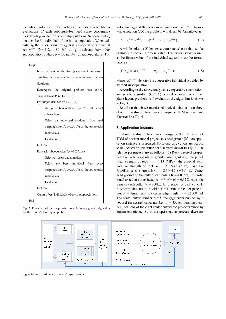
According to the above analysis, a cooperative coevolution-
ary genetic algorithm (CCGA) is used to solve the cutters’
plane layout problem. A flowchart of the algorithm is shown
in Fig. 3.
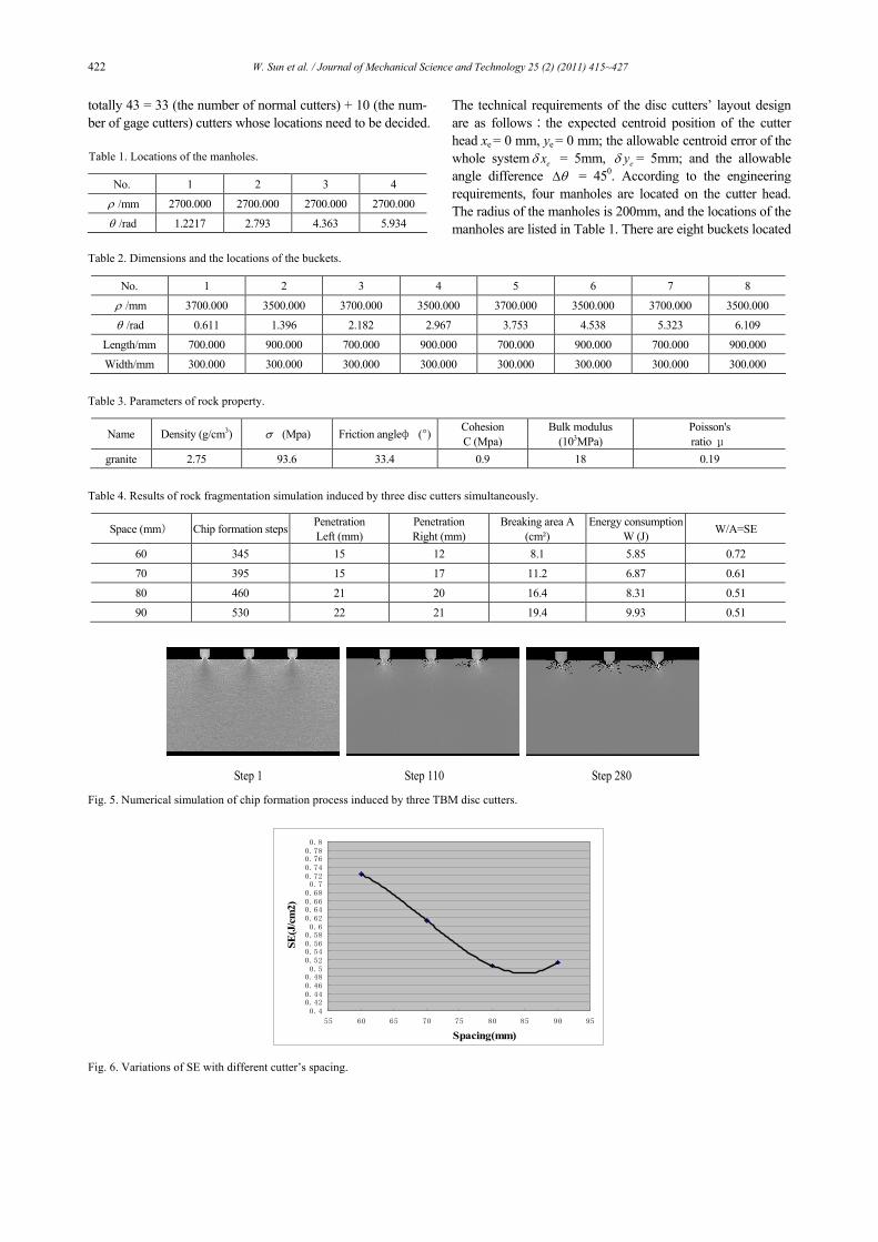
Based on the above-mentioned analysis, the solution flow-
chart of the disc cutters’ layout design of TBM is given and
illustrated as Fig. 4.
5. Application instance
Taking the disc cutters’ layout design of the full face rock
TBM of a water tunnel project as a background [23], an appli-
cation instance is presented. Forty-one disc cutters are needed
to be located on the cutter head surface shown in Fig. 1. The
relative parameters are as follows: (1) Rock physical proper-
ties: the rock is mainly in granite-based geology,the punch
shear strength of rock τ = 7-13 (MPa),the uniaxial com-
pressive strength of rock cσ = 50~93.6 (MPa),and the
Brazilian tensile strength tσ = 2.14~4.0 (MPa). (2) Cutter
head geometry: the cutter head radius R = 4.015m,the rota-
tional speed of cutter head ω = 6 (r/min) = 0.6283 rad/s, the
mass of each cutter M = 200kg, the diameter of each cutter D
= 483mm, the cutter tip width T = 10mm, the cutter penetra-
tion P = 7mm,and the cutter edge angle α = 1.5708 rad.
The center cutter number n1 = 8, the gage cutter number n2 =
10, and the normal cutter number n3 = 33. As mentioned ear-
lier, locations of the eight center cutters are pre-determined by
human experience. So in the optimization process, there are
Begin
Initialize the original cutters’ plane layout problem;
Initialize a cooperative co-evolutionary genetic
algorithm;
Decompose the original problem into n(n≥2)
subproblems SPi (i=1,2,3…n);
For subproblem SPi (i=1,2,3…n)
Assign a subpopulation Pi (i=1,2,3…n) for each
subproblem;
Select an individual randomly from each
subpopulation Pi (i=1,2…N) as the cooperative
individuals;
Evaluation;
End For
For each subpopulation Pi (i=1,2,3…n)
Selection, cross and mutation;
Select the best individual from every
subpopulation Pi (i=1,2…N) as the cooperative
individuals;
Evaluation;
End For
Output s best individuals of every subpopulation;
End
Fig. 3. Flowchart of the cooperative coevolutionary genetic algorithm
for the cutters’ plane layout problem.
Fig. 4. Flowchart of the disc cutters’ layout design.
422 W. Sun et al. / Journal of Mechanical Science and Technology 25 (2) (2011) 415~427
totally 43 = 33 (the number of normal cutters) + 10 (the num-
ber of gage cutters) cutters whose locations need to be decided.
The technical requirements of the disc cutters’ layout design
are as follows:the expected centroid position of the cutter
head xe = 0 mm, ye = 0 mm; the allowable centroid error of the
whole system exδ = 5mm, eyδ = 5mm; and the allowable
angle difference θ∆ = 450. According to the engineering
requirements, four manholes are located on the cutter head.
The radius of the manholes is 200mm, and the locations of the
manholes are listed in Table 1. There are eight buckets located
Table 1. Locations of the manholes.
No. 1 2 3 4
ρ /mm 2700.000 2700.000 2700.000 2700.000
θ /rad 1.2217 2.793 4.363 5.934
Table 2. Dimensions and the locations of the buckets.
No. 1 2 3 4 5 6 7 8
ρ /mm 3700.000 3500.000 3700.000 3500.000 3700.000 3500.000 3700.000 3500.000
θ /rad 0.611 1.396 2.182 2.967 3.753 4.538 5.323 6.109
Length/mm 700.000 900.000 700.000 900.000 700.000 900.000 700.000 900.000
Width/mm 300.000 300.000 300.000 300.000 300.000 300.000 300.000 300.000
Table 3. Parameters of rock property.
Name Density (g/cm3) σ (Mpa) Friction angleφ (°) Cohesion
C (Mpa)
Bulk modulus
(103MPa)
Poisson's
ratio μ
granite 2.75 93.6 33.4 0.9 18 0.19
Table 4. Results of rock fragmentation simulation induced by three disc cutters simultaneously.
Space (mm) Chip formation steps Penetration
Left (mm)
Penetration
Right (mm)
Breaking area A
(cm²)
Energy consumption
W (J) W/A=SE
60 345 15 12 8.1 5.85 0.72
70 395 15 17 11.2 6.87 0.61
80 460 21 20 16.4 8.31 0.51
90 530 22 21 19.4 9.93 0.51
Step 1 Step 110 Step 280
Fig. 5. Numerical simulation of chip formation process induced by three TBM disc cutters.
0.40.420.440.460.480.5
0.520.540.560.580.6
0.620.640.660.680.7
0.720.740.760.780.8
55 60 65 70 75 80 85 90 95
SE(J/cm2)
Spacing(mm)
Fig. 6. Variations of SE with different cutter’s spacing.
W. Sun et al. / Journal of Mechanical Science and Technology 25 (2) (2011) 415~427 423
in the cutter head symmetrically, and their locations are listed
in Table 2.
Based on the above-mentioned requirements, the first step
is to determine the disc cutters’ spacing. The disc cutters’
spacing layout design includes the spacing design of the center
cutters, the normal cutters and the gage cutters. First, the
rock’s fragmentation simulation software RFPA2D is used and
the numerical simulation method of reference [11] is adopted
to simulate the rock fragmentation process induced by three
disc cutters of TBM under different spacing. Properties of the
rock are listed in Table 3. Parameters of the rock’s fragmenta-
tion simulation are as follows: the penetration of each simula-
tion step is 0.005 mm/step; the model rock size is about
200mm*600mm; and the confining pressure is 20Mpa. The
value of the confining pressure is mainly decided by the geo-
logical report. The results of the rock’s fragmentation simula-
tion induced by three disc cutters simultaneously are listed in
Table 4. The numerical simulation process of chip formation
induced by the three disc cutters is shown in Fig. 5. The spac-
ing between the three disc cutters is set from 60 mm to 90 mm.
The variations curve of SE with different cutter spacing is
shown in Fig. 6. From Fig. 6, it can be seen that that the opti-
Table 5. Locations of the disc cutters from the center of the cutter head.
No. 1 3 3 4 5 6 7 8 9 10 11 12 13
ρ /mm 70 170 270 370 470 570 670 770 855 940 1025 1110 1195
θ /rad 0.00 3.14 0.00 3.14 1.57 4.71 1.57 4.71 5.59 2.60 3.72 0.79 2.02
γ /rad 0 0 0 0 0 0 0 0 0 0 0 0 0
No. 14 15 16 17 18 19 20 21 22 23 24 25 26
ρ /mm 1280 1365 1450 1535 1620 1705 1790 1875 1960 2045 2130 2215 2300
θ /rad 3.11 0.17 5.11 5.98 2.43 4.23 0.53 3.74 2.03 4.85 0.19 5.55 3.09
γ /rad 0 0 0 0 0 0 0 0 0 0 0 0 0
No. 27 28 29 30 31 32 33 34 35 36 37 38 39
ρ /mm 2385 2470 2555 2640 2725 2810 2895 2980 3065 3150 3235 3320 3405
θ /rad 0.79 2.31 3.91 1.71 0.54 5.09 3.65 5.71 1.96 5.95 0.85 2.37 -0.02
γ /rad 0 0 0 0 0 0 0 0 0 0 0 0 0
No. 40 41 42 43 44 45 46 47 48 49 50 51
ρ /mm 3490 3575 3646.7 3715.2 3778.6 3835 3882.7 3922.5 3953.9 3978.8 3998.3 4015
θ /rad 3.35 4.90 2.83 4.39 2.05 0.11 5.45 3.61 1.25 2.66 4.70 0.88
γ /rad 0 0 0.16 0.31 0.47 0.63 0.78 0.91 1.03 1.13 1.19 1.22
Table 6. Performance indexes of the optimal layout scheme solved by two methods.
Methods vM / KN.m sF /KN
mx /mm my /mm Overlapping area Unsuccessive disc
cutters’ number Time/s
Original human experience scheme 154.840 11.558 -2.135 -0.221 0.000 4 Unknown
Best 0.028 0.001 0.080 1.010 0.000 0 1189 CCGA
Average 6.623 4.382 -0.532 0.262 0.000 0 1202
Table 7. The maximum stresses and deformations of the cutter head solved the CCGA under different load conditions.
Von Stress/MPa Max Deformation/mm
Normal load Full load Normal load Full load conditions Methods
Max. aver. Max. aver. Max. aver. Max. aver.
CCGA 111.06 24.30 324.466 70.203 0.438 0.195 1.36 0.905
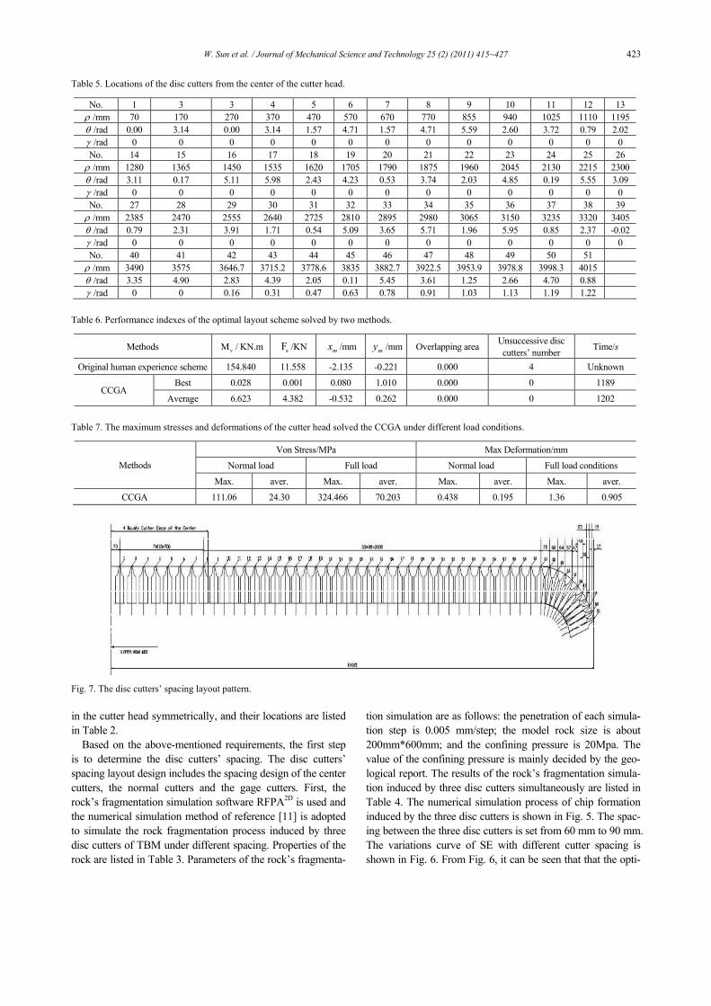
Fig. 7. The disc cutters’ spacing layout pattern.
424 W. Sun et al. / Journal of Mechanical Science and Technology 25 (2) (2011) 415~427
mal spacing is about 83-86mm, so 85mm is selected as the
normal cutter’s spacing in this study. Second, for the center
cutters’ spacing, the rolling distance of the center cutters usu-
ally is smaller than that of the normal cutters under the same
cutter spacing at the same times. Moreover, the rock is of
good integrity; it is hard to fully use the shear ability of the
cutters to cut the rock if the center cutter spacing is set at a
little smaller value, so the center cutter spacing is set 100mm
in this study. Last, Eq. (8) is adopted to determine the gage
cutters’ spacing. The radius ρ measured from the center of
the cutter head of all the three types of cutters is listed in Tab.
5. The disc cutters’ spacing layout pattern is shown in Fig. 7.
As can be seen from Fig. 7, with the increasing of the radius
of the cutters, the cutters’ spacing are decreasing. Moreover,
the gage cutters’ spacing decreases more obviously to balance
their lives and abrasions.
After the design of the cutters’ spacing, the next step is the
cutters’ plane layout design. The basic problem of this step is
to optimize the objective function formulated by Eq. (9),
whilst satisfying all the technological constraints given by Eqs.
(10)-(13). A CCGA is designed and programmed to solve this
problem.
The numerical experiments are run on an AT-compatible
PC, with 1700MHz Intel processor with 4 and 512 Mb Mem-
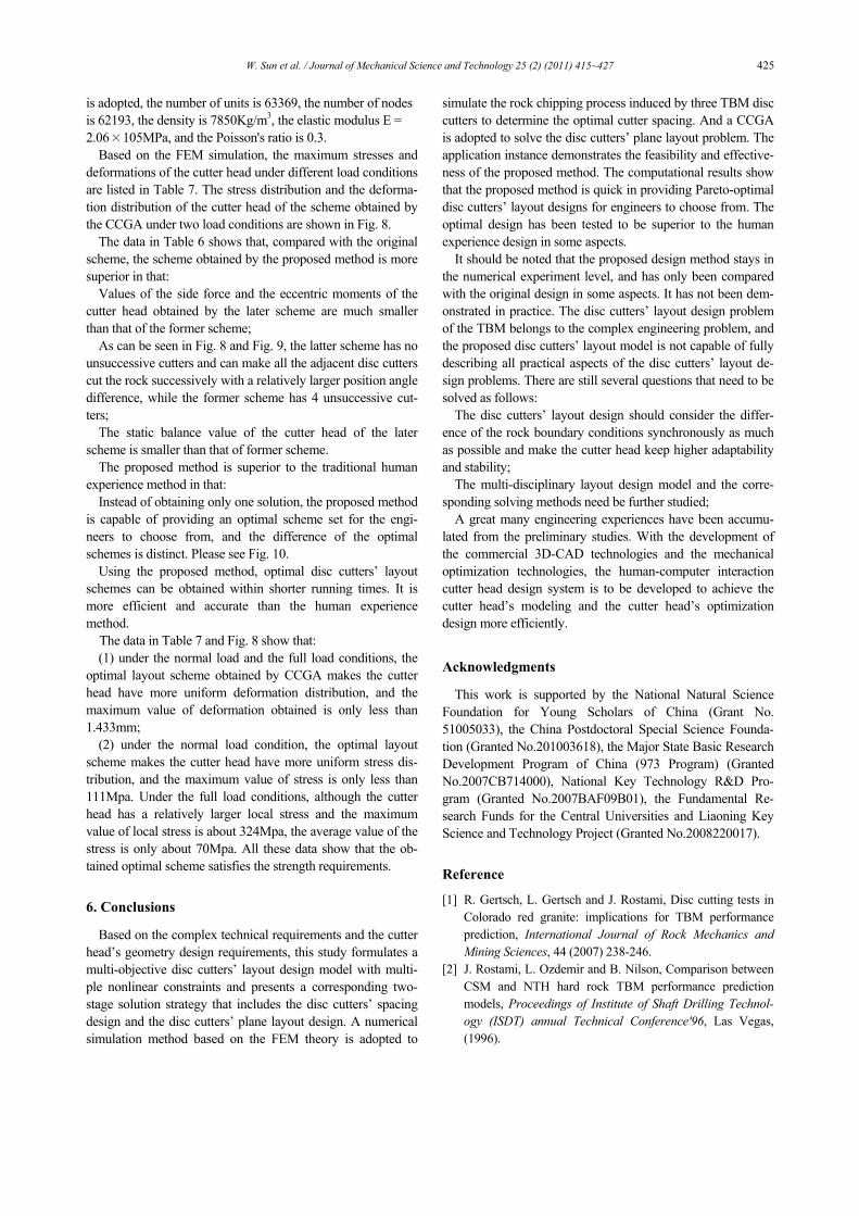
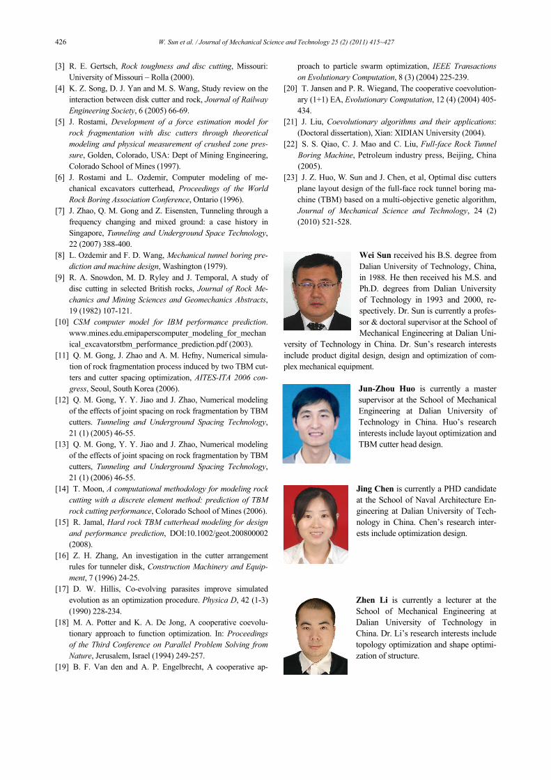
ory. The CCGA is run for totally 30 times. The performance
indexes of the optimal layout scheme and the original scheme
designed by using human experience are listed in Table 6. The
original human experience design is illustrated as Fig. 9. The
optimal layout scheme obtained by the CCGA is illustrated as
Fig. 10.
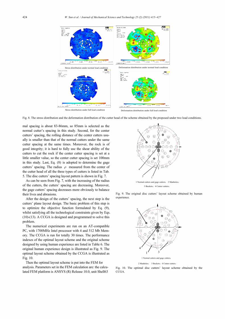
Then the optimal layout scheme is put into the FEM for
analysis. Parameters set in the FEM calculation are: the calcu-
lated FEM platform is ANSYS (R) Release 10.0, unit Shell63
Stress distribution under normal load condition Deformation distribution under normal load condition
Stress distribution under full load condition Deformation distribution under full load condition
Fig. 8. The stress distribution and the deformation distribution of the cutter head of the scheme obtained by the proposed under two load conditions.
1 Normal cutters and gage cutters; 2 Manholes;
3 Buckets;4 Center cutters;
4
2
3 1
Fig. 9. The original disc cutters’ layout scheme obtained by human
experience.
4
2
3 1
1 Normal cutters and gage cutters;
2 Manholes; 3 Buckets;4 Center cutters;
Fig. 10. The optimal disc cutters’ layout scheme obtained by the
CCGA.
W. Sun et al. / Journal of Mechanical Science and Technology 25 (2) (2011) 415~427 425
is adopted, the number of units is 63369, the number of nodes
is 62193, the density is 7850Kg/m3, the elastic modulus E =
2.06×10⁵MPa, and the Poisson's ratio is 0.3.
Based on the FEM simulation, the maximum stresses and
deformations of the cutter head under different load conditions
are listed in Table 7. The stress distribution and the deforma-
tion distribution of the cutter head of the scheme obtained by
the CCGA under two load conditions are shown in Fig. 8.
The data in Table 6 shows that, compared with the original
scheme, the scheme obtained by the proposed method is more
superior in that:
Values of the side force and the eccentric moments of the
cutter head obtained by the later scheme are much smaller
than that of the former scheme;
As can be seen in Fig. 8 and Fig. 9, the latter scheme has no
unsuccessive cutters and can make all the adjacent disc cutters
cut the rock successively with a relatively larger position angle
difference, while the former scheme has 4 unsuccessive cut-
ters;
The static balance value of the cutter head of the later
scheme is smaller than that of former scheme.
The proposed method is superior to the traditional human
experience method in that:
Instead of obtaining only one solution, the proposed method
is capable of providing an optimal scheme set for the engi-
neers to choose from, and the difference of the optimal
schemes is distinct. Please see Fig. 10.
Using the proposed method, optimal disc cutters’ layout
schemes can be obtained within shorter running times. It is
more efficient and accurate than the human experience
method.
The data in Table 7 and Fig. 8 show that:
(1) under the normal load and the full load conditions, the
optimal layout scheme obtained by CCGA makes the cutter
head have more uniform deformation distribution, and the
maximum value of deformation obtained is only less than
1.433mm;
(2) under the normal load condition, the optimal layout
scheme makes the cutter head have more uniform stress dis-
tribution, and the maximum value of stress is only less than
111Mpa. Under the full load conditions, although the cutter
head has a relatively larger local stress and the maximum
value of local stress is about 324Mpa, the average value of the
stress is only about 70Mpa. All these data show that the ob-
tained optimal scheme satisfies the strength requirements.
6. Conclusions
Based on the complex technical requirements and the cutter
head’s geometry design requirements, this study formulates a
multi-objective disc cutters’ layout design model with multi-
ple nonlinear constraints and presents a corresponding two-
stage solution strategy that includes the disc cutters’ spacing
design and the disc cutters’ plane layout design. A numerical
simulation method based on the FEM theory is adopted to
simulate the rock chipping process induced by three TBM disc
cutters to determine the optimal cutter spacing. And a CCGA
is adopted to solve the disc cutters’ plane layout problem. The
application instance demonstrates the feasibility and effective-
ness of the proposed method. The computational results show
that the proposed method is quick in providing Pareto-optimal
disc cutters’ layout designs for engineers to choose from. The
optimal design has been tested to be superior to the human
experience design in some aspects.
It should be noted that the proposed design method stays in
the numerical experiment level, and has only been compared
with the original design in some aspects. It has not been dem-
onstrated in practice. The disc cutters’ layout design problem
of the TBM belongs to the complex engineering problem, and
the proposed disc cutters’ layout model is not capable of fully
describing all practical aspects of the disc cutters’ layout de-
sign problems. There are still several questions that need to be
solved as follows:
The disc cutters’ layout design should consider the differ-
ence of the rock boundary conditions synchronously as much
as possible and make the cutter head keep higher adaptability
and stability;
The multi-disciplinary layout design model and the corre-
sponding solving methods need be further studied;
A great many engineering experiences have been accumu-
lated from the preliminary studies. With the development of
the commercial 3D-CAD technologies and the mechanical
optimization technologies, the human-computer interaction
cutter head design system is to be developed to achieve the
cutter head’s modeling and the cutter head’s optimization
design more efficiently.
Acknowledgments
This work is supported by the National Natural Science
Foundation for Young Scholars of China (Grant No.
51005033), the China Postdoctoral Special Science Founda-
tion (Granted No.201003618), the Major State Basic Research
Development Program of China (973 Program) (Granted
No.2007CB714000), National Key Technology R&D Pro-
gram (Granted No.2007BAF09B01), the Fundamental Re-
search Funds for the Central Universities and Liaoning Key
Science and Technology Project (Granted No.2008220017).
Reference
[1] R. Gertsch, L. Gertsch and J. Rostami, Disc cutting tests in
Colorado red granite: implications for TBM performance
prediction, International Journal of Rock Mechanics and
Mining Sciences, 44 (2007) 238-246.
[2] J. Rostami, L. Ozdemir and B. Nilson, Comparison between
CSM and NTH hard rock TBM performance prediction
models, Proceedings of Institute of Shaft Drilling Technol-
ogy (ISDT) annual Technical Conference'96, Las Vegas,
(1996).
426 W. Sun et al. / Journal of Mechanical Science and Technology 25 (2) (2011) 415~427
[3] R. E. Gertsch, Rock toughness and disc cutting, Missouri: University of Missouri – Rolla (2000).
[4] K. Z. Song, D. J. Yan and M. S. Wang, Study review on the interaction between disk cutter and rock, Journal of Railway Engineering Society, 6 (2005) 66-69.
[5] J. Rostami, Development of a force estimation model for rock fragmentation with disc cutters through theoretical modeling and physical measurement of crushed zone pres-sure, Golden, Colorado, USA: Dept of Mining Engineering, Colorado School of Mines (1997).
[6] J. Rostami and L. Ozdemir, Computer modeling of me-chanical excavators cutterhead, Proceedings of the World Rock Boring Association Conference, Ontario (1996).
[7] J. Zhao, Q. M. Gong and Z. Eisensten, Tunneling through a frequency changing and mixed ground: a case history in Singapore, Tunneling and Underground Space Technology, 22 (2007) 388-400.
[8] L. Ozdemir and F. D. Wang, Mechanical tunnel boring pre-diction and machine design, Washington (1979).
[9] R. A. Snowdon, M. D. Ryley and J. Temporal, A study of disc cutting in selected British rocks, Journal of Rock Me-chanics and Mining Sciences and Geomechanics Abstracts, 19 (1982) 107-121.
[10] CSM computer model for IBM performance prediction. www.mines.edu.emipaperscomputer_modeling_for_mechanical_excavatorstbm_performance_prediction.pdf (2003).
[11] Q. M. Gong, J. Zhao and A. M. Hefny, Numerical simula-tion of rock fragmentation process induced by two TBM cut-ters and cutter spacing optimization, AITES-ITA 2006 con-gress, Seoul, South Korea (2006).
[12] Q. M. Gong, Y. Y. Jiao and J. Zhao, Numerical modeling of the effects of joint spacing on rock fragmentation by TBM cutters. Tunneling and Underground Spacing Technology, 21 (1) (2005) 46-55.
[13] Q. M. Gong, Y. Y. Jiao and J. Zhao, Numerical modeling of the effects of joint spacing on rock fragmentation by TBM cutters, Tunneling and Underground Spacing Technology, 21 (1) (2006) 46-55.
[14] T. Moon, A computational methodology for modeling rock cutting with a discrete element method: prediction of TBM rock cutting performance, Colorado School of Mines (2006).
[15] R. Jamal, Hard rock TBM cutterhead modeling for design and performance prediction, DOI:10.1002/geot.200800002 (2008).
[16] Z. H. Zhang, An investigation in the cutter arrangement rules for tunneler disk, Construction Machinery and Equip-ment, 7 (1996) 24-25.
[17] D. W. Hillis, Co-evolving parasites improve simulated evolution as an optimization procedure. Physica D, 42 (1-3) (1990) 228-234.
[18] M. A. Potter and K. A. De Jong, A cooperative coevolu-tionary approach to function optimization. In: Proceedings of the Third Conference on Parallel Problem Solving from Nature, Jerusalem, Israel (1994) 249-257.
[19] B. F. Van den and A. P. Engelbrecht, A cooperative ap-
proach to particle swarm optimization, IEEE Transactions on Evolutionary Computation, 8 (3) (2004) 225-239.
[20] T. Jansen and P. R. Wiegand, The cooperative coevolution-ary (1+1) EA, Evolutionary Computation, 12 (4) (2004) 405-434.
[21] J. Liu, Coevolutionary algorithms and their applications: (Doctoral dissertation), Xian: XIDIAN University (2004).
[22] S. S. Qiao, C. J. Mao and C. Liu, Full-face Rock Tunnel Boring Machine, Petroleum industry press, Beijing, China (2005).
[23] J. Z. Huo, W. Sun and J. Chen, et al, Optimal disc cutters plane layout design of the full-face rock tunnel boring ma-chine (TBM) based on a multi-objective genetic algorithm, Journal of Mechanical Science and Technology, 24 (2) (2010) 521-528.
Wei Sun received his B.S. degree from Dalian University of Technology, China, in 1988. He then received his M.S. and Ph.D. degrees from Dalian University of Technology in 1993 and 2000, re-spectively. Dr. Sun is currently a profes-sor & doctoral supervisor at the School of Mechanical Engineering at Dalian Uni-
versity of Technology in China. Dr. Sun’s research interests include product digital design, design and optimization of com-plex mechanical equipment.
Jun-Zhou Huo is currently a master supervisor at the School of Mechanical Engineering at Dalian University of Technology in China. Huo’s research interests include layout optimization and TBM cutter head design.
Jing Chen is currently a PHD candidate at the School of Naval Architecture En-gineering at Dalian University of Tech-nology in China. Chen’s research inter-ests include optimization design.
Zhen Li is currently a lecturer at the School of Mechanical Engineering at Dalian University of Technology in China. Dr. Li’s research interests include topology optimization and shape optimi-zation of structure.
W. Sun et al. / Journal of Mechanical Science and Technology 25 (2) (2011) 415~427 427
Xu Zhang is currently a post-doctor at the School of Mechanical Engineering at Dalian University of Technology in Dalian, China. Dr. Zhang’s research interests include reliability optimization design and TBM main bearing design.
Li Guo is currently an assistant profes-sor at the School of Mechanical Engi-neering at Dalian University of Technol-ogy in China. Her research interests in-clude disc cutter optimization and inter-action between disc cutter and rock.
Haifeng Zhao received his Ph.D. from Northeastern University in 2008. Zhao is currently a senior engineer of Nhi Group Tunnel Boring Machine Com-pany in China.
Yu Zhao is currently a Ph.D. candidate of Zhejiang University in China. Zhao is also an engineer of Nhi Group Tunnel Boring Machine Company in China.