Embed Size (px)
Citation preview

Part Number 900-406 Revision H October 2011
XPort AR Integration Guide

XPort AR Integration Guide 2
Copyright and Trademark © 2011 Lantronix. All rights reserved. No part of the contents of this book may be transmitted or reproduced in any form or by any means without the written permission of Lantronix. Printed in the United States of America.
XPort is a registered trademark of Lantronix.
Ethernet is a trademark of XEROX Corporation. UNIX is a registered trademark of The Open Group. Windows 95, Windows 98, Windows 2000, Windows NT, and Windows XP are trademarks of Microsoft Corp. Netscape is a trademark of Netscape Communications Corporation.
Contacts Lantronix Corporate Headquarters 167 Technology Drive Irvine, CA 92618, USA Phone: 949-453-3990 Fax: 949-450-7249
Technical Support Online: www.lantronix.com/support
Sales Offices For a current list of our domestic and international sales offices, go to the Lantronix web site at www.lantronix.com/about/contact.
Disclaimers Operation of this equipment in a residential area is likely to cause interference to other devices, in which case the user, at his or her own expense, will be required to take whatever measures may be required to correct the interference.
Note: This product has been designed to comply with the limits for a Class B digital device pursuant to Part 15 of FCC and EN55022:1998 Rules when properly enclosed and grounded. These limits are designed to provide reasonable protection against radio interference in a residential installation. This equipment generates, uses, and can radiate radio frequency energy, and if not installed and used in accordance with this guide, may cause interference to radio communications.
Changes or modifications to this device not explicitly approved by Lantronix will void the user’s authority to operate this device.
The information in this guide may change without notice. The manufacturer assumes no responsibility for any errors that may appear in this guide.
Note: With the purchase of XPort AR, the OEM agrees to an OEM firmware license agreement that grants the OEM a non-exclusive, royalty-free firmware license to use and distribute the binary firmware image provided, only to the extent necessary to use the XPort AR hardware. For further details, please see the XPort AR OEM firmware license agreement.

XPort AR Integration Guide 3
Revision History Date Rev. Comments June 2005 A Initial Release March 2007 B Correct pin numbers June 2006 C Updated figure 2-7, and identified Pin 1; corrected references to
CP12 & CP13 June 2010 D Minor corrections. Update company contact info. September 2010 E Minor corrections. Updated schematics under heading
“Recommended PCB Layout”. May 2011 F Updated figures 2-1, 2-6, 2-7 and 2-8. June 2011 G Updated figures 2-7 and 2-8. October 2011 H Updated security information.
For the latest revision of this product document, please check our online documentation at www.lantronix.com/support/documentation.

XPort AR Integration Guide 4
Contents Copyright and Trademarks ________________________________________________ 2 Contacts ______________________________________________________________ 2 Disclaimers ____________________________________________________________ 2 Revision History ________________________________________________________ 3 List of Figures __________________________________________________________ 5 List of Tables ___________________________________________________________ 6
1: Introduction 7 About the Integration Guide _______________________________________________ 7 Additional Documentation _________________________________________________ 7
2: Description and Specifications 8 The XPort AR __________________________________________________________ 8 XPort AR Block Diagram __________________________________________________ 9 PCB Interface __________________________________________________________ 9
Standard Pins (Evaluation Board XP300200K-01) __________________________ 9 PoE Pins __________________________________________________________ 10
Ethernet Interface ______________________________________________________ 11 Reset ________________________________________________________________ 11 LEDs ________________________________________________________________ 11 Dimensions ___________________________________________________________ 12 Recommended PCB Layout ______________________________________________ 14
XPort Compatibility __________________________________________________ 14 Product Information Label ________________________________________________ 15 Technical Specifications _________________________________________________ 16
3: Evaluation Kit 17 Contents of the Kit______________________________________________________ 17 Evaluation Board Description _____________________________________________ 17
Major Features _____________________________________________________ 17 Evaluation Board Major Components _______________________________________ 18
Major Components __________________________________________________ 19 XPort AR _____________________________________________________________ 19 Power Switch _________________________________________________________ 19 Reset Switch __________________________________________________________ 19 Headers ______________________________________________________________ 19
JP1: Signal Access Header ___________________________________________ 19 JP2: LED Header ___________________________________________________ 20 JP3: Input Switch Header _____________________________________________ 20

Contents
XPort AR Integration Guide 5
JP4: Pull-Up Header _________________________________________________ 21 JP5: GND Header ___________________________________________________ 21
Disconnect Jumpers ____________________________________________________ 21 JP6: Disconnect Jumper Header _______________________________________ 21 JP7: Disconnect Jumper Header _______________________________________ 22 JP8: Disconnect Jumper Header _______________________________________ 22
LEDs ________________________________________________________________ 23 LED1 – LED4: Signal Monitoring LEDs __________________________________ 23 LED5 – LED8: RS-232 Activity Monitoring LEDs ___________________________ 23 LED9: Power LEDs __________________________________________________ 23
Test Switches _________________________________________________________ 23 Prototyping Area _______________________________________________________ 23 RS-232 Serial Interfaces _________________________________________________ 24 PoE Socket ___________________________________________________________ 25 Ground Turret _________________________________________________________ 25 Power Supply _________________________________________________________ 25 Schematic ____________________________________________________________ 25 Board Layout __________________________________________________________ 28
Component Identification _____________________________________________ 28
A: Compliance and Warranty Information 29 Compliance Information _________________________________________________ 29 Warranty _____________________________________________________________ 29
List of Figures Figure 2-1. Side View of the XPort AR _______________________________________ 8Figure 2-2. XPort AR Block Diagram ________________________________________ 9Figure 2-3. XPort AR LEDs _______________________________________________ 12Figure 2-4. Front View ___________________________________________________ 12Figure 2-5. Bottom View _________________________________________________ 13Figure 2-6. Side View ___________________________________________________ 13Figure 2-7. PCB Layout (Top View) ________________________________________ 14Figure 2-8. Hole Pattern and Mounting Dimensions (Bottom View) ________________ 15Figure 2-9. Product Label ________________________________________________ 15Figure 3-1. Evaluation Board _____________________________________________ 18Figure 3-2. Evaluation Board (Diagram) ____________________________________ 18Figure 3-3. Evaluation Board Schematic ____________________________________ 26Figure 3-4. Board Layout ________________________________________________ 28

Contents
XPort AR Integration Guide 6
List of Tables Table 2-1. Standard Interface Signals ______________________________________ 10Table 2-2. PoE Interface Signals __________________________________________ 10Table 2-3. Ethernet Interface Signals ______________________________________ 11Table 2-4. XPort AR LED Functions ________________________________________ 12Table 2-5. Technical Specifications ________________________________________ 16Table 3-1. JP1 Connections ______________________________________________ 20Table 3-2. JP2 Connections ______________________________________________ 20Table 3-3. JP3 Connections ______________________________________________ 21Table 3-4. JP4 Connections ______________________________________________ 21Table 3-5. JP5 Connections ______________________________________________ 21Table 3-6. JP6 Connections ______________________________________________ 22Table 3-7. JP7 Connections ______________________________________________ 22Table 3-8. JP8 Connections ______________________________________________ 22Table 3-9. RS-232 Signals _______________________________________________ 24Table 3-10. Board Components ___________________________________________ 28

XPort AR Integration Guide 7
1: Introduction About the Integration Guide
This guide provides the information needed to test the XPort® AR device server on the XPort AR Evaluation Board. This manual is intended for engineers responsible for integrating the XPort AR into their product.
Additional Documentation For supporting product documentation, or the most current version of this document, please visit the Lantronix Web site at www.lantronix.com/support/documentation.
Document Description XPort AR Getting Started Provides the steps for getting the hardware and software
up and running. XPort AR User Guide Provides information needed to configure, use, and
update the XPort firmware. XPort AR Command Reference Lists and explains XPort AR command line and XML
commands. Com Port Redirector User Guide Provides information on using the Windows-based utility
to create a virtual com port.

XPort AR Integration Guide 8
2: Description and Specifications The XPort AR embedded device server is a complete network-enabling solution enclosed within an RJ45 package. This miniature device server empowers original equipment manufacturers (OEMs) to quickly and easily go to market with networking and web page serving capabilities built into their products.
The XPort AR The XPort AR contains Lantronix’s own DSTni controller, with 256 Kbytes of SRAM, 16 Kbytes of boot ROM, and integrated AMD 10/100 PHY.
The XPort AR also contains the following:
New powerful operating system with additional new features. Two full serial ports with all hardware handshaking signals (or three serial ports without
handshaking signals). 13 pins are configurable as general purpose I/O. Supports fully compliant Power over Ethernet (PoE) designs by using PoE compliant
magnetics and passing through both the used and unused pairs. Memory: 4 MB Flash and 1.25 MB RAM. 3.3-volt serial interface. All I/O pins are 5V tolerant. Ethernet magnetics. Power supply filters. Reset circuit. +1.8V regulator. Ethernet LEDs.
The XPort AR requires +3.3-volt power and is designed to operate over an industrial temperature range (see technical data).
Figure 2-1. Side View of the XPort AR

2: Description and Specifications
XPort AR Integration Guide 9
XPort AR Block Diagram The following drawing is a block diagram of the XPort AR showing the relationships of the components.
Figure 2-2. XPort AR Block Diagram
PCB Interface
Standard Pins (Evaluation Board XP300200K-01) The XPort AR has 26 electrical pins. There are 20 pins that form two rows of ten. These 20 pins form the standard interface between the XPort AR and the circuit in which it is installed. These include dedicated serial as well as 11 programmable I/O pins (Configurable Pins, or CPs). The other group of six pins is for PoE.
The standard signals are 3.3V CMOS logic level but are 5V tolerant. These signals are typically connected to internal devices, such as a relays, sensors, or UARTs. For prototype and evaluation work or applications where an external RS-232 interface is required, RS-232 transceivers are available on the XPort AR evaluation board. Optionally, disconnect them using the jumpers provided if they are not needed.
Note: Typically, after booting up CP pins are in an unstable state for a few seconds. However, the state of the CP pins in the XPort-AR is initially high-impedance, suitable for an input. To use a CP pin as an output, the pin may be biased high or low with a resistor to +V or ground so it will be "defined" as either 1 or 0 during this initial time.

2: Description and Specifications
XPort AR Integration Guide 10
Table 2-1. Standard Interface Signals
Signal Name XPort AR Pin #
Primary Functions
GND 4 Signal Ground
VCC 5 +3.3V Power In _________
Reset 8 External Reset In
TXDA 9 Serial Data Out, Channel A
RXDA 12 Serial Data In, Channel A
CP01 13 Programmable I/O or RTSA flow control
CP02 16 Programmable I/O or DTRA flow control
CP03 17 Programmable I/O or CTSA flow control
CP04 3 Programmable I/O or DSRA flow control
CP05 7 Programmable I/O or DCDA flow control
CP06 2 Programmable I/O or TXDB flow control
CP07 10 Programmable I/O or RXDB flow control
CP08 1 Programmable I/O or RTSB flow control
CP09 6 Programmable I/O or DTRB flow control
CP10 20 Programmable I/O or CTSB flow control
CP11 19 Programmable I/O or DSRB/DCDB flow control
CP12 11 I2C clock
CP13 14 I2C data
Reserved 15 Reserved
Reserved 18 Reserved
PoE Pins XPort AR is PoE-ready; it allows a fully compliant PoE circuit to be implemented that uses the Ethernet signals entering the XPort AR’s RJ-45 jack. When the XPort AR’s RJ-45 jack is connected to a PoE compliant switch, pins 21, 22, 25, and 26 pass through the necessary Ethernet signals to allow a PoE powered-device circuit to negotiate and receive power from the switch.
Table 2-2. PoE Interface Signals
Signal Name XPort R Pin #
Primary Functions
POE12 22 Center tap from 1 & 2
POE36 25 Center tap from 3 & 6
POE45 21 Ethernet pins 4 & 5
POE78 26 Ethernet pins 7 & 8
CHSGND 23 Chassis Ground

2: Description and Specifications
XPort AR Integration Guide 11
Signal Name XPort R Pin #
Primary Functions
CHSGND 24 Chassis Ground
Note: The four shield tabs are also Chassis Ground. Separate Chassis Ground appropriately from the Signal Ground and route so as to safely dissipate electrostatic discharge.
Ethernet Interface The RJ-45 connector, Ethernet magnetics, PHY and Ethernet status LEDs are all integrated into the XPort AR.
Table 2-3. Ethernet Interface Signals
Signal Name DIR Contact Primary Function Note
TX+ Out 1 Differential Ethernet Transmit Data + Magnetics center tap
provides signal POE12 TX- Out 2 Differential Ethernet Transmit Data -
RX+ In 3 Differential Ethernet Receive Data + Magnetics center tap
provides signal POE36 RX- In 6 Differential Ethernet Receive Data -
Not Used 4 (Terminated) Pins 4 and 5 are tied together, terminated and form POE45 Not Used 5 (Terminated)
Not Used 7 (Terminated) Pins 7 and 8 are tied together, terminated and form POE78 Not Used 8 (Terminated)
CHSGND Shield Chassis Ground
Reset The XPort AR reset pin is an input-only pin and connects to an 811-type reset IC. Internal to the 811 is a 20k pull-up. This is the only influence the XPort AR has on the reset pin. This input is intended for a push-button switch type manual reset. If no external reset control is desired, leave this pin floating.
LEDs The XPort AR contains the following LEDs:
Link (bi-color, left LED) Activity (bi-color, right LED)

2: Description and Specifications
XPort AR Integration Guide 12
Figure 2-3. XPort AR LEDs
Table 2-4. XPort AR LED Functions
Link LED Left Side Activity LED Right Side Color Meaning Color Meaning Off No Link Off No Activity Amber 10 Mbps Amber Half Duplex Green 100 Mbps Green Full Duplex
Dimensions The XPort AR dimensions are shown in the following illustrations:
Figure 2-4. Front View

2: Description and Specifications
XPort AR Integration Guide 13
Figure 2-5. Bottom View
Figure 2-6. Side View

2: Description and Specifications
XPort AR Integration Guide 14
Recommended PCB Layout The hole pattern and mounting dimensions for the XPort AR are shown in the following illustration. For proper heat dissipation, it is recommended that the PCB have approximately 1 square inch of copper attached to the shield tabs. The shield tabs are an important source of heat sinking for the device.
Figure 2-7. PCB Layout (Top View)
XPort Compatibility The XPort AR is designed for the PCB layout to accommodate either an XPort AR or the original Lantronix XPort. To accomplish this, a few extra holes are required. The hole pattern and mounting dimensions for this combination XPort/XPort AR footprint are shown in the following drawing:

2: Description and Specifications
XPort AR Integration Guide 15
Figure 2-8. Hole Pattern and Mounting Dimensions (Bottom View)
Product Information Label The product information label contains important information about your specific unit, such as its product ID (name), bar code, part number, serial number, and Ethernet (MAC) address.
Figure 2-9. Product Label
MAC Address
Part Number Revision
Serial Number

2: Description and Specifications
XPort AR Integration Guide 16
Technical Specifications Table 2-5. Technical Specifications
Category Description CPU Lantronix DSTni-EX 186 CPU with 256 kB zero wait state SRAM, 512 kB flash, 16 kB
boot ROM
Memory 2 KB EEPROM 1 MB 70ns SRAM 4 MB 70ns Flash
Reset Circuit Internal 350ms (±200ms) reset pulse. Triggered by power-on, power drop-out or external reset input. Power drop-out reset triggered at 2.93V (range: 2.79-3.00V)
Serial Interface CMOS (Asynchronous) 3.3V-level signals Rate is software selectable: 300 bps up to 230400 bps (depending on the software)
Serial Line Formats Data bits: 7 or 8 Stop bits: 1 or 2 Parity: odd, even, none
Modem Control RTS, DTR, CTS, DSR, DCD
Flow Control XON/XOFF (software), CTS/RTS (hardware), None
Programmable I/O 13 PIOs (software selectable), sink minimum of 4.4mA, source minimum of 6.4mA
Network Interface RJ45 Ethernet 10Base-T or 100Base-TX (auto-sensing)
Compliance Ethernet: Version 2.0/IEEE 802.3 (electrical) Ethernet II frame type IEEE 802.3af (when PoE-enabled)
Protocols Supported ARP, UDP/IP, TCP/IP, Telnet, ICMP, SNMP, DHCP, BOOTP, TFTP, Auto IP, SMTP, and HTTP
LEDs 10Base-T and 100Base-TX Link Full/half duplex activity
Management Internal web server, SNMP (read only) Serial login, Telnet login, XML
Email SMTP client: can send email to multiple users, can attach files to email Configurable Pins (CPs) can trigger emails
Security SSL v2, SSH v3, AES 128-bit encryption, password protection, IP address filtering, locking features, hardened OS and stack
Internal Web Server Servers static and dynamic CGI-based pages Storage capacity: 1.3 MB using industry standard filesystem
Material Metal shell, thermoplastic case
Temperature Operating range: -40°C to +85°C (-40°F to 185°F)
Shock/Vibration Non-operational shock: 500 g's Non-operational vibration: 20 g's
Warranty Two year limited warranty
Included Software Windows™ -based DeviceInstaller configuration software and Windows™-based Com Port Redirector

XPort AR Integration Guide 17
3: Evaluation Kit The XPort AR Evaluation Kit includes everything needed to integrate XPort AR into a product design.
Contents of the Kit The evaluation kit contains the following items:
XPort AR Evaluation Board XPort AR Device Server +3.3VDC Universal Power Supply CAT5e UTP RJ45M/M Ethernet cable .025” square-post jumper wires RS-232 cable, DE-9, F/F CD with software utilities and documentation (in PDF format)
Evaluation Board Description The XPort AR Evaluation Board provides many features for evaluating the Lantronix XPort AR embedded device server. These features allow both quick start-up for immediate interaction with the XPort AR and its operating system, as well as a prototyping area and easy access to all signals for evaluating advanced features.
Major Features The major features of the evaluation board include:
Headers offering: ♦ All 18 signals of the XPort AR interface. ♦ Monitoring LEDs to jumper to XPort AR Configurable Pins (CPs). ♦ Input control switches to jumper to XPort AR CPs. ♦ Pull-up resistors to jumper to XPort AR CPs. ♦ Signal ground (GND) to jumper to XPort AR CPs.
Prototyping Area: ♦ 258 holes on 100 mil centers. ♦ Every header pin is also connected to the adjacent prototyping hole. ♦ 8 power and 8 ground holes are available for powering prototype circuits.
LEDs: ♦ Power (Blue). ♦ Tx (Green) & Rx (Yellow) activity for both ports A and B. ♦ Four available to jumper to CPs for monitoring.
Power: ♦ 3.3V input with power switch. ♦ PoE socket containing all signals necessary to receive power over Ethernet and return
3.3V to the board. Serial Ports:
♦ Two DE-9 male connectors ♦ Transceivers can be disconnected from XPort AR by jumper removal (if not used).
Switches:

3: Evaluation Kit
XPort AR Integration Guide 18
♦ Power on/off. ♦ Push button reset. ♦ Two available to jumper to CPs for generating input.
Ground: ♦ Turret available for scope probe alligator clip connection to signal ground.
XPort AR Footprint: ♦ Accommodates both XPort AR and the original XPort (without sockets).
Evaluation Board Major Components Figure 3-1. Evaluation Board
Figure 3-2. Evaluation Board (Diagram)

3: Evaluation Kit
XPort AR Integration Guide 19
Major Components The major components of the evaluation board include:
XPort AR Power Switch Reset Switch Headers Disconnect Jumpers LEDs
Test Switches Prototyping Area RS-232 Serial Ports PoE Socket Ground Turret Power Input Connector
XPort AR The XPort AR is placed in the upper left corner of the evaluation board and is referenced as J1.
Note: The footprint used for J1 on the evaluation board is compatible with both the XPort AR and the original Lantronix XPort.
Power Switch The two positions of the power switch are On and Off/PoE. In the On position, the evaluation board gets its power from the 3.3 VDC input jack. In the Off/PoE position, the evaluation board uses 3.3 VDC from the PoE socket S1 (if a circuit is attached that makes it available). This provides a convenient On/Off switch in either case.
Reset Switch The reset switch grounds the reset pin on the XPort AR. The XPort AR reset pin is an input-only pin and connects to an 811-type reset IC. Internal to the 811 is a 20k pull-up and is the only influence the XPort AR has on the reset pin.
Headers The headers provide access to all of the XPort AR signals, as well as to circuits for I/O control and monitoring.
JP1: Signal Access Header This header provides access to each XPort AR signal. Use these pins to monitor activity with an oscilloscope or to jumper to one of the four monitoring LEDs. When a CP is configured as an input, it can be connected with a jumper to GND, a pull-up, or switch with pull-up and switchable ground contact.
Note: Typically, after booting up CP pins are in an unstable state for a few seconds. However, the state of the CP pins in the XPort-AR is initially high-impedance, suitable for an input. To use a CP pin as an output, the pin may be biased high or low with a resistor to +V or ground so it will be "defined" as either 1 or 0 during this initial time.

3: Evaluation Kit
XPort AR Integration Guide 20
Table 3-1. JP1 Connections
JP1 Pin # Connects To: 1 TXDA 2 RXDA 3 CP01 (RTSA) 4 CP02 (DTRA) 5 CP03 (CTSA) 6 CP04 (DSRA) 7 CP05 (DCDA) 8 CP06 (TXDB) 9 CP07 (RXDB) 10 CP08 (RTSB) 11 CP09 (DTRB) 12 CP10 (CTSB) 13 CP11 (DSRB) 14 CP12 (I2CCLK) 15 CP13 (I2CDTA)
16 ____________ RESET
17 Reserved 18 Reserved
JP2: LED Header This header provides access to each of the monitoring LEDs. These pins can be connected with a jumper wire to any of the JP1 pins to monitor the signal level with the corresponding LED. When a high is present, the LED illuminates. Test LEDs by using a jumper to any of the JP4 pull-up pins. Each LED has a unique color to facilitate identifying the LEDs that are on.
Table 3-2. JP2 Connections
JP2 Pin # Connects To:
1 LED1 – green
2 LED2 – yellow
3 LED3 – orange
4 LED4 – red
JP3: Input Switch Header This header provides access to each of the two input control switches. These pins can be connected with a jumper wire to any of the JP1 pins to control the signal level with the corresponding switch. When a switch is in the center position, it is off. This allows a 1K pull-up resistor to create a high on the corresponding pin. When a switch is turned on, it connects the corresponding pin to ground. Each switch has a latched-on down position and a momentary-on up position

3: Evaluation Kit
XPort AR Integration Guide 21
Table 3-3. JP3 Connections
JP3 Pin # Connects To: 1 Switch 1
2 Switch 2
JP4: Pull-Up Header This header provides access to 1k pull-up resistors. These pins can be connected with a jumper wire to any of the JP1 pins to set the signal level to high (in cases where the corresponding CP is configured as an input). Use the JP3 switched signals for signals that you wish to change between high and low relatively often.
Table 3-4. JP4 Connections
JP4 Pin # Connects To: 1 1k pull-up resistor
2 1k pull-up resistor
3 1k pull-up resistor
4 1k pull-up resistor
JP5: GND Header This header provides access to signal ground. These pins can be connected with a jumper wire to any of the JP1 pins to set the signal level to low (in cases where the corresponding CP is configured as an input). For signals that you wish to change between high and low relatively often, use the JP3 switched signals.
Table 3-5. JP5 Connections
JP5 Pin # Connects To: 1 Signal ground (GND)
2 Signal ground (GND)
3 Signal ground (GND)
4 Signal ground (GND)
Disconnect Jumpers
JP6: Disconnect Jumper Header This header provides jumper positions to connect the XPort AR to the RS-232 Port A transceiver when an RS-232 serial interface is desired. Install any number/combination of these jumpers, depending on which RS-232 signals are required and which XPort AR signals are to perform functions other than RS-232 related.

3: Evaluation Kit
XPort AR Integration Guide 22
Table 3-6. JP6 Connections
JP6 Pin #
Connects To: JP6 Pin #
Connects To:
1 RS-232 XCVR, TXDA Input 2 XPort AR, TXDA
3 RS-232 XCVR, RTSA Input 4 XPort AR, CP01
5 RS-232 XCVR, DTRA Input 6 XPort AR, CP02
7 RS-232 XCVR, RXDA Output 8 XPort AR, RXDA
9 RS-232 XCVR, CTSA Output 10 XPort AR, CP03
11 RS-232 XCVR, DSRA Output 12 XPort AR, CP04
13 RS-232 XCVR, DCDA Output 14 XPort AR, CP05
JP7: Disconnect Jumper Header This header provides jumper positions to connect the XPort AR to the RS-232 Port B transceiver when this RS-232 serial interface is desired. Any number/combination of these jumpers may be installed depending on which RS-232 signals are required and which XPort AR signals are to perform functions other than RS-232 related.
Table 3-7. JP7 Connections
JP7 Pin #
Connects To: JP7 Pin #
Connects To:
1 RS-232 XCVR, TXDB Input 2 XPort AR, CP06
3 RS-232 XCVR, RTSB Input 4 XPort AR, CP08
5 RS-232 XCVR, DTRB Input 6 XPort AR, CP09
7 RS-232 XCVR, RXDB Output 8 XPort AR, CP07
9 RS-232 XCVR, CTSB Output 10 XPort AR, CP10
JP8: Disconnect Jumper Header This header provides jumper positions to connect the XPort AR to the RS-232 Port B transceiver when this RS-232 serial interface is desired and requires either DSR or DCD. Since CP12 and CP13 are dedicated to an I2C function, only CP11 remains to serve both DSR and DCD on port B. This jumper has two positions: 1-2 or 2-3. In the 1-2 position, it connects the XPort AR signal CP11 to the DSR output for Port B. In the 2-3 position, it connects the XPort AR signal CP11 to the DCD output for Port B. This choice is made based on whether the serial interface intends to use DSR or DCD.
Table 3-8. JP8 Connections
JP8 Pin # Connects To: 1 RS-232 XCVR, DSRB Output
2 XPort AR, CP11
3 RS-232 XCVR, DCDB Output

3: Evaluation Kit
XPort AR Integration Guide 23
LEDs The LEDs on the XPort AR evaluation board provide indications of power on, RS-232 port activity, and states of selected signals.
LED1 – LED4: Signal Monitoring LEDs These LEDs are used to monitor the state of selected XPort AR signals. A signal selected for monitoring is connected to an LED by placing a jumper wire between the signal’s pin in header JP1 and an LED control pin in header JP2. These LEDs are driven by transistors. As such, there is very little load placed on the observed signal. This allows the LEDs to be used to observe a signal in a prototype circuit without affecting the circuit’s behavior.
LED5 – LED8: RS-232 Activity Monitoring LEDs These LEDs are used to monitor activity on the RS-232 ports. These LEDs are driven by a circuit that detects a low level on the transmit signals or receive signals and generates a minimum length drive signal to the LEDS of a few hundred milliseconds. Since RS-232 signals are high when data is not transmitted, these LEDs are off when there is no activity.
Note: These LEDs can be used as additional signal state monitors when the RS-232 transceivers are not being used. To accomplish this, jumper the signals to be monitored to JP6-p1, JP6-p7, JP7-p1, JP7-p7.
LED9: Power LEDs This blue LED illuminates any time the evaluation board is powered.
Test Switches The test switches, SW1 and SW2 generate switchable high/low input signals to XPort AR CPs that are configured for input. These are 3- position switches (on, off, and momentary). When a switch is in the center position (off), it allows a pull-up resistor to create a high on the corresponding header pin. When a switch is turned on, it connects its corresponding header pin to ground. Each switch has a latched-on down position and a momentary-on up position. These switchable signals are connected to the desired CP pin with jumpers placed between JP3 and JP1.
Prototyping Area The prototyping area provides 258 holes on 0.100” centers for addition of prototype circuitry to the XPort AR evaluation board. Most of the holes are floating and available for any added component lead to be placed in them. A few holes are pre-connected for convenience and neatness of the circuit to be prototyped. These pre-connected holes have a thin-line silkscreen boarder around them. These bordered groups of pre-connected holes are marked with the reference designators PR1-PR5, GND and 3.3V.
PR1 is the group of holes adjacent to header JP1. Each hole in PR1 is connected to the adjacent JP1 pin. When prototype circuitry is to be connected to an XPort AR signal, solder a wire between the appropriate PR1 hole and the appropriate prototype circuit lead (or place the prototype component’s lead directly in the PR1 hole). This keeps the JP1 pins available for jumpers to LEDs or switches.
PR2 provides the same type of convenient connections to the observation LEDs for use in prototype circuits.
Similarly, PR3 provides connections to SW1 and SW2.

3: Evaluation Kit
XPort AR Integration Guide 24
PR4 is the group of holes adjacent to the pull-up header, JP4. Each of the four holes is connected to the adjacent pin on JP4. A separate 1k pull-up resistor is connected to each of these holes/pins. These are available for use as needed in a prototype circuit.
The four holes grouped as PR5 and the four holes grouped as GND (lower left corner of prototyping area) are all directly connected to the signal ground plane of the evaluation board. These eight holes provide good signal ground connections for prototype circuitry.
The eight holes grouped as 3.3V provide direct connection to the 3.3V power plane of the evaluation board. These eight holes provide good power plane connections for prototype circuitry.
RS-232 Serial Interfaces The RS-232 serial interfaces are implemented with transceivers that convert 3.3V CMOS levels to RS-232 levels. A null-modem serial cable with 9-pin connectors (F/F) is the only item needed to connect to another DTE device such as a PC.
The table below lists the RS-232 signals.
Note: All XPort AR serial interface signal pins, except 9 and 12, are CPs that can be optionally set for functions other than their RS-232 function.
The jumpers in JP6, JP7, and JP8 determine whether or not the XPort AR pins are connected to the RS-232 transceivers. When using RS-232, the signals used must have their associated jumper installed in JP6, JP7, and JP8.
Table 3-9. RS-232 Signals
XPort AR PC
Signal Pin # Jumper Direction DE-9 Pin # Connection DCDA (CP05) 7 JP6, 13-14 In P1-1 -- RXDA 12 JP6, 7-8 In P1-2 TXD TXDA 9 JP6, 1-2 Out P1-3 RXD DTRA (CP02) 16 JP6, 5-5 Out P1-4 DSR GND 4 -- -- P1-5 GND DSRA (CP04) 3 JP6, 11-12 In P1-6 DTR RTSA (CP01) 13 JP6, 3-4 Out P1-7 CTS CTSA (CP03) 17 JP6, 9-10 In P1-8 RTS -- -- -- -- P1-9 -- DCDB (CP11) 19 JP8, 3-2 In P2-1 -- RXDB (CP07) 10 JP7, 7-8 In P2-2 TXD TXDB (CP06) 2 JP7, 1-2 Out P2-3 RXD DTRB (CP09) 6 JP7, 5-6 Out P2-4 DSR GND 4 -- -- P2-5 GND DSRB (CP11) 19 JP8, 1-2 In P2-6 DTR RTSB (CP08) 1 JP7, 3-4 Out P2-7 CTS CTSB (CP10) 20 JP7, 9-10 In P2-8 RTS -- -- -- -- P2-9 --

3: Evaluation Kit
XPort AR Integration Guide 25
PoE Socket The PoE Socket (Samtec: SSQ-105-01-G-D; Oupiin: 2044-2 X 5 G S; Molex: 15-44-3205) provides access to both the used pairs and unused pairs from the Ethernet. It provides connection to the evaluation board’s 3.3V power switch, signal ground, and chassis ground. The socket’s pinouts are:
Pin 1, PoE45: Ethernet signals 4 and 5. (These two Ethernet pins are connected together inside the XPort AR and exit out of this pin.)
Pin 2, PoE12: Ethernet signals 1 and 2. (This pin comes from the center tap of the XPort AR’s PoE compliant magnetics connected to the Ethernet pins 1 and 2.)
Pins 3 & 4, 3V3PoE: Connect to the evaluation board’s power switch. Pins 5 & 6: Connect to the evaluation board’s chassis ground. (Connection is optional.) Pins 7 & 8, GND: Connect to the evaluation board’s signal ground. Pin 9, PoE36: Ethernet signals 3 and 6. (This pin comes from the center tap of the XPort
AR’s PoE compliant magnetics that are connected to Ethernet pins 3 and 6.)
Pin 10, PoE78: Ethernet signals 7 and 8. (These two Ethernet pins are connected together inside the XPort AR and exit out of this pin.)
Ground Turret The turret marked GND (lower right corner of prototyping area) is a convenient way to connect an oscilloscope or DMM ground clip to signal ground. This type of ground connection has proven to be a much more secure way to keep an alligator-type clip in place. For smaller clip leads, the pins of JP5 are also connected to signal ground.
Power Supply The evaluation board typically uses 3.3 VDC regulated input power entering through a 1.3 mm input power jack. It is possible to power the board from 3.3 VDC input to the PoE socket, S1; this is usually only performed in combination with an external PoE circuit also connected to S1. The evaluation kit provides a 3.3 VDC 1.3 mm power module.
It is recommend that chassis ground of the evaluation board be connected to an earth ground. Chassis ground on the evaluation board is found at the four mounting holes, the D-connector shells, and the XPort AR shell.
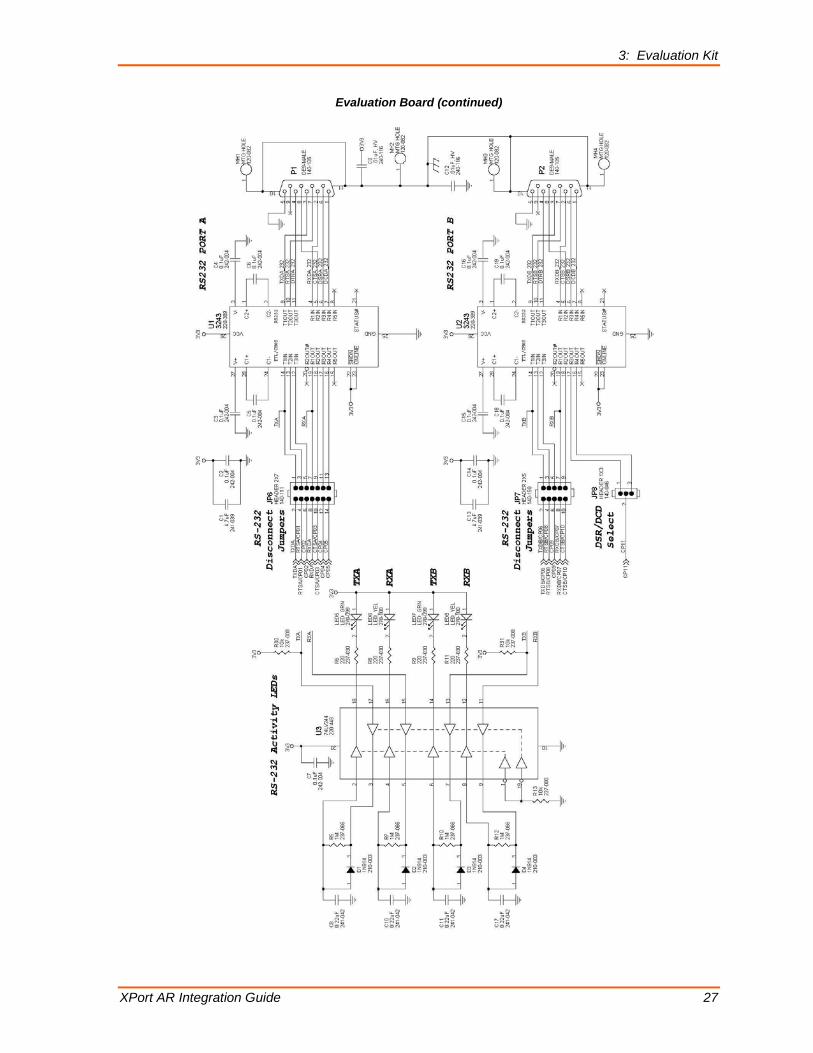
Schematic The XPort AR evaluation board schematic shows the relationships of all of the previously described components.

3: Evaluation Kit
XPort AR Integration Guide 26
Figure 3-3. Evaluation Board Schematic
3: Evaluation Kit
XPort AR Integration Guide 27
Evaluation Board (continued)

3: Evaluation Kit
XPort AR Integration Guide 28
Board Layout Figure 3-4. Board Layout
Component Identification
Table 3-10. Board Components
Label Function Label Function
GND1 Signal Ground Turret LED5 Port A Tx Activity Monitor LED, Green
J1 XPort AR LED6 Port A Rx Activity Monitor LED, Yellow
J2 3.3VDC Power Jack LED7 Port B Tx Activity Monitor LED, Green
JP1 XPort AR Signal Access Header LED8 Port B Rx Activity Monitor LED, Yellow
JP2 Signal Monitor LED Header LED9 Power LED, Blue
JP3 Test Switch Header P1 Port A, DE-9 Male Connector
JP4 Pull-Up Header P2 Port B, DE-9 Male Connector
JP5 GND Header S1 PoE Socket
JP6 Port A Disconnect Jumper Header SW1 Test Switch 1
JP7 Port B Disconnect Jumper Header SW2 Test Switch 2
JP8 Port B DSR/DCD Select Header SW3 Reset Push-Button Switch
LED1 Signal Monitoring LED, Green SW4 Power Slide Switch
LED2 Signal Monitoring LED, Yellow U1 RS-232 Transceiver (3243)
LED3 Signal Monitoring LED, Orange U2 RS-232 Transceiver (3243)
LED4 Signal Monitoring LED, Red U3 Activity LED Drive Buffer (74_244)

XPort AR Integration Guide 29
A: Compliance and Warranty Information Compliance Information
(According to ISO/IEC Guide 22 and EN 45014)
Manufacturer’s Name & Address: Lantronix 167 Technology Drive, Irvine, CA 92618 USA
Declares that the following product:
Product Name Model: XPort AR Embedded Device Server
Conforms to the following standards or other normative documents:
Radiated and conducted emissions Class B limits of EN 55022:1998
EN55024: 1998 + A1: 2001
Direct & Indirect ESD EN61000-4-2: 1995
RF Electromagnetic Field Immunity EN61000-4-3: 1996
Electrical Fast Transient/Burst Immunity EN61000-4-4: 1995
Surge Immunity EN61000-4-5: 1995
RF Common Mode Conducted Susceptibility EN61000-4-6: 1996
Power Frequency Magnetic Field Immunity EN61000-4-8: 1993
Voltage Dips and Interrupts EN61000-4-11: 1994
Manufacturer’s Contact: Lantronix 167 Technology Drive, Irvine, CA 92618 USA Phone: 949-453-3990 Fax: 949-450-7249
Warranty For details on the Lantronix warranty replacement policy, please go to our Web site at www.lantronix.com/support/warranty.