Embed Size (px)
Citation preview

ORGANISATION INTERNATIONALE
DE MÉTROLOGIE LÉGALE
INTERNATIONAL ORGANIZATION
OF LEGAL METROLOGY
OIML R 60Edition 2000 (E)
ERRATUM:INTERNATIONAL
RECOMMENDATION
Metrological regulation for load cells
THIS ERRATUM ONLY CONCERNS THE ENGLISH VERSION OF R 60 (2000)

NOTE: Since the publication of OIML R 60(E) Edition 2000, a number of points have been corrected. These are listedbelow and should be taken into account when using OIML R 60.
Page in Clause CorrectionR 60 (2000) or section to be applied
40 C.2.4.3 Replace the existing text by:
Divide CM by (T2 – T1) and multiply the result by 5 for classes B, C, and D, or by 2 for class A. This gives the change in v per 5 °C for classes B, C, and D, or in v per 2 °C for class A.
40 C.2.4.4 Replace the existing text by:
Multiply the preceding result by [(Dmax – Dmin) /n] /vmin to give the final result inunits of vmin per 5 °C for classes B, C, and D, or units of vmin per 2 °C for class A;this final result must not exceed pLC.
44 C.4.3 Replace the symbol “<” by the symbol “≤” :
n = nmax – 500 and n = nmax – 1 000 (provided that n ≥ 500)
44 C.4.4 Replace the symbol “<” by the symbol “≤” (twice):
vmin ≤ v
vmin ≤ (Dmax – Dmin) / nmax
47 Annex D Under the section “Information concerning the pattern”, “Power voltage”, secondline, insert a colon (:) after “V”:
or V: ____________ V
50 Summary Change the reference between the two tables from “C.3” to “C.4”:of the test
50 Summary Change the second table as below:of the test
Erratum to OIML R 60(E) (Edition 2000) November 2000
ParagraphDescription
nmax nmax – 500 nmax – 1 000
No. Pass Fail Pass Fail Pass Fail
C.4.2,C.4.3,C.4.5
C.4.4
Check all calculations using values of n at nmax
and at lower than nmax
Worst case figure for minimum dead load output return error (in mass units) = DR = _____________ see Note 3
Check that vmin ≤Dmax – Dmin
nmax
56 Table D.5 Left column: Change the reference in the bottom line of the “Exercise cells”paragraph from “Figure A.2” to “Figure A.1”.
56 Pass/Fail section In the Pass/Fail box section underneath Table D.5, third line, change “DR < 0.5 V” to “DR ≤ 0.5 V”.
56 Pass/Fail section In the Pass/Fail box section underneath Table D.5, fourth line, change “MDLOR with-in DR requirements:” to “DR within manufacturer specified DR requirements:”.
57 Note 1 Delete “/kPa” from the first line of Note 1.

Metrological regulation for load cells
Réglementation métrologique des cellules de pesée
OIM
L R
60
Editi
on20
00 (E
)
OIML R 60Edition 2000 (E)
ORGANISATION INTERNATIONALE
DE MÉTROLOGIE LÉGALE
INTERNATIONAL ORGANIZATION
OF LEGAL METROLOGY
INTERNATIONAL
RECOMMENDATION

OIML R 60: 2000 (E)
2
Contents
Foreword ........................................................................................................................................................................... 4
1 Scope ................................................................................................................................................................. 5
2 Terminology (Terms and definitions) ............................................................................................................. 52.1 General terms ...................................................................................................................................................... 52.2 Metrological characteristics of a load cell ......................................................................................................... 52.3 Range, capacity and output terms ..................................................................................................................... 62.4 Measurement and error terms ............................................................................................................................ 72.5 Influences and reference conditions .................................................................................................................. 82.6 Illustration of certain definitions ....................................................................................................................... 9
3 Units of measurement ..................................................................................................................................... 9
4 Metrological requirements .............................................................................................................................. 94.1 Principle of load cell classification .................................................................................................................... 94.2 Accuracy classes ................................................................................................................................................ 104.3 Maximum number of load cell verification intervals ..................................................................................... 104.4 Minimum load cell verification interval .......................................................................................................... 104.5 Supplementary classifications .......................................................................................................................... 104.6 Complete load cell classification ...................................................................................................................... 104.7 Presentation of information ............................................................................................................................. 114.8 OIML certificate ................................................................................................................................................ 12
5 Maximum permissible load cell errors ........................................................................................................ 125.1 Maximum permissible errors for each accuracy class ................................................................................... 125.2 Rules concerning the determination of errors ................................................................................................ 125.3 Permissible variation of results ........................................................................................................................ 135.4 Repeatability error ............................................................................................................................................ 135.5 Influence quantities ........................................................................................................................................... 135.6 Measurement standards .................................................................................................................................... 14
6 Requirements for load cells equipped with electronics ............................................................................. 146.1 General requirements ........................................................................................................................................ 146.2 Acting upon significant faults ........................................................................................................................... 156.3 Functional requirements ................................................................................................................................... 156.4 Additional tests .................................................................................................................................................. 15
7 Metrological controls ..................................................................................................................................... 167.1 Liability to legal metrological controls ............................................................................................................ 167.2 Test requirements .............................................................................................................................................. 167.3 Selection of load cells within a family ............................................................................................................. 16

OIML R 60: 2000 (E)
3
Annex A Test procedures for pattern evaluation ............................................................................................. 18A.1 Scope .................................................................................................................................................................. 18A.2 Purpose .............................................................................................................................................................. 18A.3 Test conditions .................................................................................................................................................. 18A.4 Test procedures ................................................................................................................................................. 19A.5 Recommended test sequence ........................................................................................................................... 29
Annex B Selection of load cell(s) for testing - a practical example ............................................................... 31
Annex C Test report format - General .............................................................................................................. 38C.1 Introduction ...................................................................................................................................................... 38C.2 Calculation procedures ..................................................................................................................................... 38C.3 Additional tests for load cells equipped with electronics ............................................................................... 42C.4 General notes .................................................................................................................................................... 44
Annex D Test report format - Forms ................................................................................................................ 46
Annex E OIML Certificate of conformity for load cells .................................................................................. 79E.1 Format of certificate ......................................................................................................................................... 79E.2 Contents of addendum to test certificate ........................................................................................................ 81
Index of terms .................................................................................................................................................... 83

OIML R 60: 2000 (E)
4
The International Organization of Legal Metrology(OIML) is a worldwide, intergovernmental organizationwhose primary aim is to harmonize the regulations and
metrological controls applied by the national metrologicalservices, or related organizations, of its Member States.
The two main categories of OIML publications are:
• International Recommendations (OIML R), which aremodel regulations that establish the metrological charac-teristics required of certain measuring instruments andwhich specify methods and equipment for checking theirconformity; the OIML Member States shall implementthese Recommendations to the greatest possible extent;
• International Documents (OIML D), which are inform-ative in nature and intended to improve the work of themetrological services.
OIML Draft Recommendations and Documents are devel-oped by technical committees or subcommittees which areformed by the Member States. Certain international andregional institutions also participate on a consultation basis.
Cooperative agreements are established between OIML andcertain institutions, such as ISO and IEC, with the objectiveof avoiding contradictory requirements; consequently, manu-
facturers and users of measuring instruments, test labor-atories, etc. may apply simultaneously OIML publicationsand those of other institutions.
International Recommendations and International Docu-ments are published in French (F) and English (E) and aresubject to periodic revision.
This publication - reference OIML R 60, edition 2000 - wasdeveloped by the Technical Committee TC 9 Instruments formeasuring mass and density. It was approved for finalpublication by the International Committee of LegalMetrology in 1999 and will be submitted to the InternationalConference of Legal Metrology in 2000 for formal sanction. Itsupersedes the previous edition dated 1991 (includingAnnex A, published in 1993).
OIML publications may be obtained from the Organization’sheadquarters:
Bureau International de Métrologie Légale11, rue Turgot - 75009 Paris - France
Telephone: 33 (0)1 48 78 12 82 and 42 85 27 11Fax: 33 (0)1 42 82 17 27E-mail: [email protected]: http://www.oiml.org
Foreword
OIML R 60: 2000 (E)
5
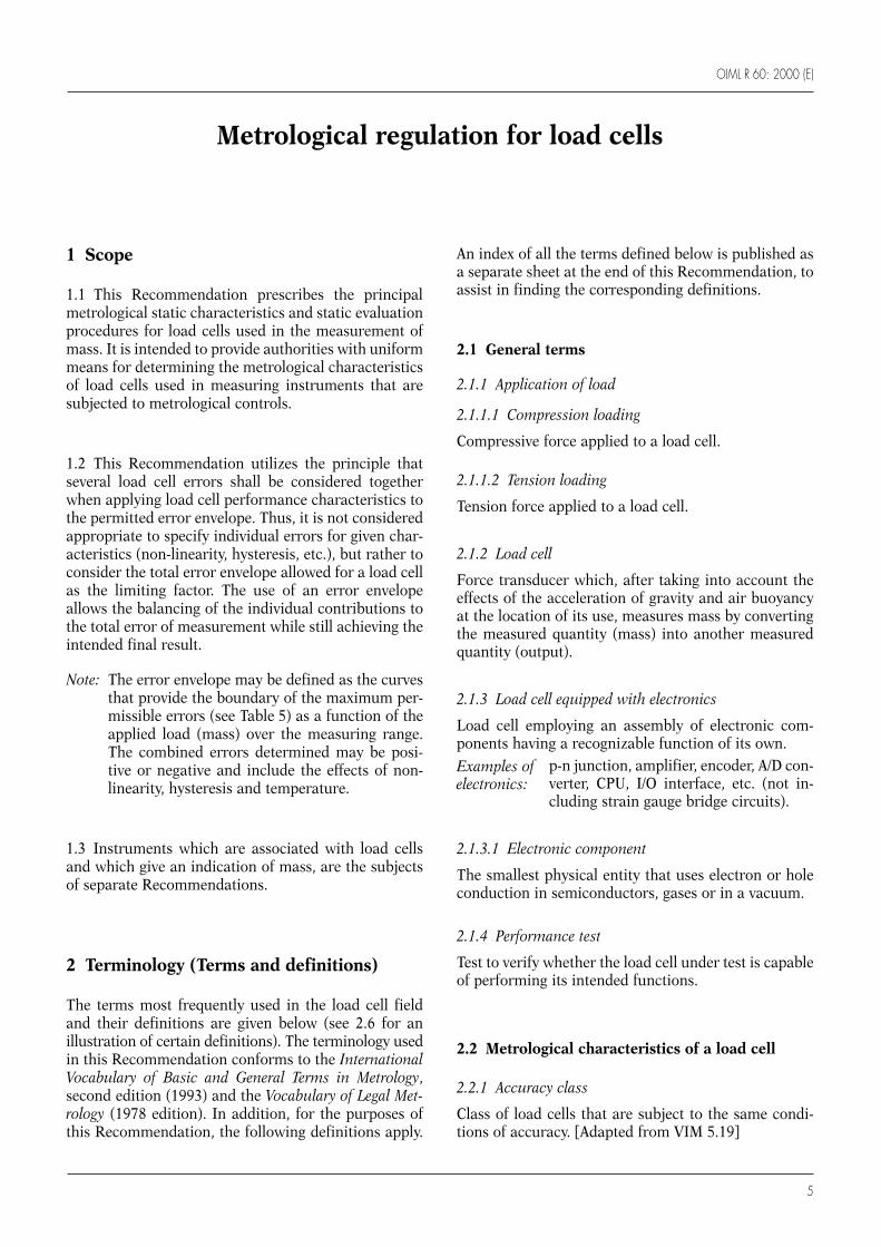
1 Scope
1.1 This Recommendation prescribes the principalmetrological static characteristics and static evaluationprocedures for load cells used in the measurement ofmass. It is intended to provide authorities with uniformmeans for determining the metrological characteristicsof load cells used in measuring instruments that aresubjected to metrological controls.
1.2 This Recommendation utilizes the principle thatseveral load cell errors shall be considered togetherwhen applying load cell performance characteristics tothe permitted error envelope. Thus, it is not consideredappropriate to specify individual errors for given char-acteristics (non-linearity, hysteresis, etc.), but rather toconsider the total error envelope allowed for a load cellas the limiting factor. The use of an error envelopeallows the balancing of the individual contributions tothe total error of measurement while still achieving theintended final result.
Note: The error envelope may be defined as the curvesthat provide the boundary of the maximum per-missible errors (see Table 5) as a function of theapplied load (mass) over the measuring range.The combined errors determined may be posi-tive or negative and include the effects of non-linearity, hysteresis and temperature.
1.3 Instruments which are associated with load cellsand which give an indication of mass, are the subjectsof separate Recommendations.
2 Terminology (Terms and definitions)
The terms most frequently used in the load cell fieldand their definitions are given below (see 2.6 for anillustration of certain definitions). The terminology usedin this Recommendation conforms to the InternationalVocabulary of Basic and General Terms in Metrology,second edition (1993) and the Vocabulary of Legal Met-rology (1978 edition). In addition, for the purposes ofthis Recommendation, the following definitions apply.
Metrological regulation for load cells
An index of all the terms defined below is published asa separate sheet at the end of this Recommendation, toassist in finding the corresponding definitions.
2.1 General terms
2.1.1 Application of load
2.1.1.1 Compression loading
Compressive force applied to a load cell.
2.1.1.2 Tension loading
Tension force applied to a load cell.
2.1.2 Load cell
Force transducer which, after taking into account theeffects of the acceleration of gravity and air buoyancyat the location of its use, measures mass by convertingthe measured quantity (mass) into another measuredquantity (output).
2.1.3 Load cell equipped with electronics
Load cell employing an assembly of electronic com-ponents having a recognizable function of its own.
p-n junction, amplifier, encoder, A/D con-verter, CPU, I/O interface, etc. (not in-cluding strain gauge bridge circuits).
2.1.3.1 Electronic component
The smallest physical entity that uses electron or holeconduction in semiconductors, gases or in a vacuum.
2.1.4 Performance test
Test to verify whether the load cell under test is capableof performing its intended functions.
2.2 Metrological characteristics of a load cell
2.2.1 Accuracy class
Class of load cells that are subject to the same condi-tions of accuracy. [Adapted from VIM 5.19]
Examples ofelectronics:
OIML R 60: 2000 (E)
6
2.2.2 Humidity symbol
Symbol assigned to a load cell that indicates the condi-tions of humidity under which the load cell has beentested.
2.2.3 Load cell family
For the purposes of type evaluation/pattern approval, aload cell family consists of load cells that are of:
• the same material or combination of materials (forexample, mild steel, stainless steel or aluminum);
• the same design of the measurement technique (forexample, strain gauges bonded to metal);
• the same method of construction (for example, shape,sealing of strain gauges, mounting method, manu-facturing method);
• the same set of specifications (for example, outputrating, input impedance, supply voltage, cable details);and
• one or more load cell groups.
Note: The examples provided are not intended to belimiting.
2.2.3.1 Load cell group
All load cells within a family possessing identical met-rological characteristics (for example, class, nmax,temperature rating, etc.).
Note: The examples provided are not intended to belimiting.
2.3 Range, capacity and output terms
2.3.1 Load cell interval
Part of the load cell measuring range into which thatrange is divided.
2.3.2 Load cell measuring range
Range of values of the measured quantity (mass) forwhich the result of measurement should not be affectedby an error exceeding the maximum permissible error(mpe) (see 2.4.9).
2.3.3 Load cell output
Measurable quantity into which a load cell converts themeasured quantity (mass).
2.3.4 Load cell verification interval (v)
Load cell interval, expressed in units of mass, used inthe test of the load cell for accuracy classification.
2.3.5 Maximum capacity (Emax)
Largest value of a quantity (mass) which may be ap-plied to a load cell without exceeding the mpe (see 2.4.9).
2.3.6 Maximum load of the measuring range (Dmax)
Largest value of a quantity (mass) which is applied to aload cell during test or use. This value shall not begreater than Emax (see 2.3.5). For the limits on Dmaxduring testing, see A.3.2.4.
2.3.7 Maximum number of load cell verificationintervals (nmax)
Maximum number of load cell verification intervalsinto which the load cell measuring range may bedivided for which the result of measurement shall notbe affected by an error exceeding the mpe (see 2.4.9).
2.3.8 Minimum dead load (Emin)
Smallest value of a quantity (mass) which may beapplied to a load cell without exceeding the mpe (see2.4.9).
2.3.9 Minimum dead load output return (DR)
Difference in load cell output at minimum dead load,measured before and after load application.
2.3.10 Minimum load cell verification interval (vmin)
Smallest load cell verification interval (mass) intowhich the load cell measuring range can be divided.
2.3.11 Minimum load of the measuring range (Dmin)
Smallest value of a quantity (mass) which is applied toa load cell during test or use. This value shall not be lessthan Emin (see 2.3.8). For the limits on Dmin duringtesting, see A.3.2.4.
2.3.12 Number of load cell verification intervals (n)
Number of load cell verification intervals into whichthe load cell measuring range is divided.

OIML R 60: 2000 (E)
7
2.3.13 Relative DR or Z
Ratio of the maximum capacity, Emax, to two times theminimum dead load output return, DR. This ratio isused to describe multi-interval instruments.
2.3.14 Relative vmin or Y
Ratio of the maximum capacity, Emax, to the minimumload cell verification interval, vmin. This ratio describesthe resolution of the load cell independent from theload cell capacity.
2.3.15 Safe load limit (Elim)
Maximum load that can be applied without producinga permanent shift in the performance characteristicsbeyond those specified.
2.3.16 Warm-up time
Time between the moment power is applied to a loadcell and the moment at which the load cell is capable ofcomplying with the requirements.
2.4 Measurement and error terms
2.4.1 Creep
Change in load cell output occurring with time whileunder constant load and with all environmental condi-tions and other variables also remaining constant.
2.4.2 Apportionment factor (pLC)
The value of a dimensionless fraction expressed as adecimal (for example, 0.7) used in determining mpe(see 2.4.9). It represents that apportionment of a wholeerror (as may apply to a weighing instrument) whichhas been assigned to the load cell alone.
2.4.3 Expanded uncertainty
Quantity defining an interval about the result of ameasurement that may be expected to encompass alarge fraction of the distribution of values that couldreasonably be attributed to the measurand. [Guide tothe Expression of Uncertainty in Measurement, BIPM,IEC, IFCC, ISO, IUPAC, IUPAP, OIML, 1993]
2.4.4 Fault
Difference between the load cell error and the load cellintrinsic error (see 2.4.8).
2.4.5 Fault detection output
Electrical representation issued by the load cell indic-ating that a fault condition exists.
2.4.6 Hysteresis error
Difference between load cell output readings for thesame applied load, one reading obtained by increasingthe load from minimum load, Dmin, and the other bydecreasing the load from maximum load, Dmax.
2.4.7 Load cell error
Difference between the load cell measurement resultand the true value of the measurand (the applied forceexpressed in mass). [Adapted from VIM 5.20]
2.4.8 Load cell intrinsic error
Error of a load cell, determined under reference con-ditions (see 2.5.3). [Adapted from VIM 5.24]
2.4.9 Maximum permissible error (mpe)
Extreme values of an error permitted by this Recom-mendation (refer to clause 5) for a load cell. [Adaptedfrom VIM 5.21]
2.4.10 Non-linearity
Deviation of the increasing load cell signal output curvefrom a straight line.
2.4.11 Repeatability
Ability of a load cell to provide successive results thatare in agreement when the same load is applied severaltimes and applied in the same manner on the load cellunder constant test conditions. [Adapted from VIM5.27]
2.4.12 Repeatability error
Difference between load cell output readings takenfrom consecutive tests under the same loading and en-vironmental conditions of measurement. [Adaptedfrom VIM 5.27]
2.4.13 Sensitivity
Ratio of a change in response (output) of a load cell toa corresponding change in the stimulus (load applied).
OIML R 60: 2000 (E)
8
Safeloadlimit, Elim
No load
Maximum load, Dmax
Minimum load, Dmin
Maximum capacity, Emax
Minimum dead load, Emin
Maximum measuring range
Load cell measuring range
2.4.14 Significant fault
Fault greater than the load cell verification interval, v.
The following are not considered significant faults,even when they exceed the load cell verification inter-val, v:
• faults arising from simultaneous and mutually inde-pendent causes;
• faults implying the impossibility to perform anymeasurements;
• faults being so serious that they are bound to benoticed by all interested in the result of measure-ment; and
• transitory faults being momentary variations in theload cell output which cannot be interpreted, mem-orized or transmitted as a measurement result.
2.4.15 Span stability
Capability of a load cell to maintain the differencebetween the load cell output at maximum load, Dmax,and the load cell output at minimum load, Dmin, over aperiod of use within specified limits.
2.4.16 Temperature effect on minimum dead load output
Change in minimum dead load output due to a changein ambient temperature.
2.4.17 Temperature effect on sensitivity
Change in sensitivity due to a change in ambient tem-perature.
2.5 Influences and reference conditions
2.5.1 Influence quantity
Quantity that is not the measurand but that affects theresult of the measurement. [VIM 2.7] (For example,temperature or humidity level at the instant the meas-urements on the load cell are being observed or re-corded.)
2.5.1.1 Disturbance
Influence quantity having a value within the limitsspecified in this Recommendation, but outside the spe-cified rated operating conditions of the load cell.
2.5.1.2 Influence factor
Influence quantity having a value within the specifiedrated operating conditions of the load cell. (Forexample, a specific temperature or a specific powervoltage in which the load cell can be tested).
2.5.2 Rated operating conditions
Conditions of use, for which the metrological charac-teristics of the load cell are intended to lie within thespecified mpe (see 2.4.9).
Note: The rated operating conditions generally specifyranges or rated values of the measurand and ofthe influence quantities. [Adapted from VIM 5.5]
2.5.3 Reference conditions
Conditions of use prescribed for testing the perform-ance of a load cell or for the intercomparison of resultsof measurements.
Note: The reference conditions generally include refer-ence values or reference ranges for the influencequantities affecting the load cell. [Adapted fromVIM 5.7]
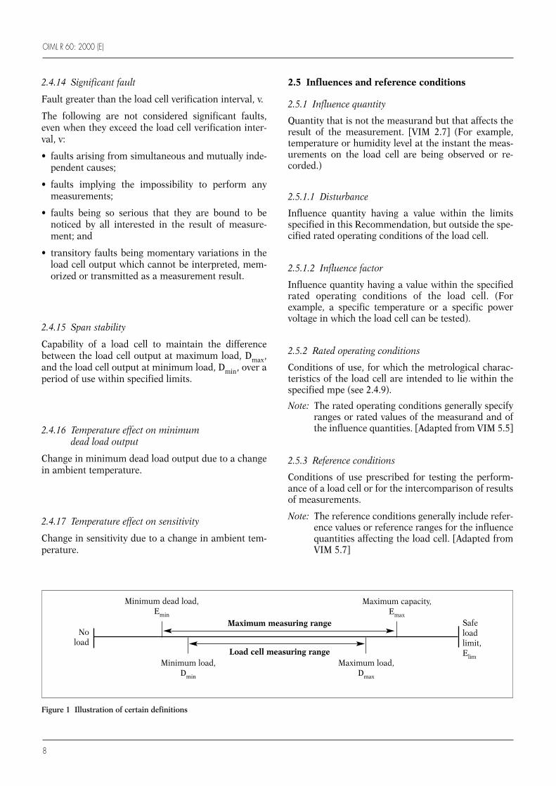
Figure 1 Illustration of certain definitions

OIML R 60: 2000 (E)
9
2.6 Illustration of certain definitions
The terms that appear above the central horizontal linein Figure 1 below are parameters that are fixed by thedesign of the load cell. The terms that appear belowthat line are parameters that are variable, dependent onthe conditions of use or in the test of a load cell (inparticular, those load cells used in weighing instru-ments).
3 Units of measurement
The units of measurement of mass are the gram (g),kilogram (kg) or tonne (t).
4 Metrological requirements
4.1 Principle of load cell classification
The classification of load cells into specific accuracyclasses is provided to facilitate their application tovarious mass measuring systems. In the application ofthis Recommendation, it should be recognized that theeffective performance of a particular load cell may beimproved by compensation within the measuring sys-tem with which it is applied. Therefore, it is not theintent of this Recommendation to require that a loadcell be of the same accuracy class as the measuringsystem in which it may be used. Nor does it require thata measuring instrument, giving indications of mass,use a load cell which has been separately approved.
Class A Class B Class C Class D
Lower limit 50 000 5 000 500 100
Upper limit Unlimited 100 000 10 000 1 000
Table 1 Maximum number of load cell verification intervals (nmax) according to accuracy class
Maximum number of load cell verificationintervals, stated in units of 1 000:e.g. 3 represents 3 000
1.5 represents 1 500
Humidity classification1. NH2. SH or3. CH or no symbol
Special temperature limitse.g. – 5/30 represents
– 5 °C to + 30 °CNote: This is only needed
when the temperaturelimits are differentfrom – 10 °C to + 40 °C
Accuracy class designationA - Class AB - Class BC - Class CD - Class D
Symbol for different types of loads
Tension
Compression
Beam(shear or bending)
Universal
C 3 NH ↑ – 5/30For example
↑↓↓↑
↓ or ↑
↑ ↓↓ ↑
Figure 2 Illustration of standard classification symbols
OIML R 60: 2000 (E)
10
4.2 Accuracy classes
Load cells shall be ranked, according to their overallperformance capabilities, into four accuracy classeswhose designations are as follows:
Class A;Class B;Class C;Class D.
4.3 Maximum number of load cell verificationintervals
The maximum number of load cell verification inter-vals, nmax, into which the load cell measuring range canbe divided in a measuring system shall be within thelimits fixed in Table 1.
4.4 Minimum load cell verification interval
The minimum load cell verification interval, vmin, shallbe specified.
4.5 Supplementary classifications
Load cells shall also be classified by the type of loadapplied to the load cell, i.e. compression loading ortension loading. A load cell may bear different classi-fications for different types of load applied to the loadcell. The type of load for which the classification(s)applies(y) shall be specified. For multiple capacity loadcells, each capacity shall be classified separately.
4.6 Complete load cell classification
The load cell shall be classified according to six parts:
(1) accuracy class designation (see 4.2 and 4.6.1);(2) maximum number of load cell verification intervals
(see 4.3 and 4.6.2);(3) type of load, if necessary (see 4.5 and 4.6.3);(4) special limits of working temperature, if necessary
(see 4.6.4);(5) humidity symbol, if necessary (see 4.6.5); and (6) additional characterization information, as listed
below.
An example illustrating the six parts of the load cellclassification is shown in Figure 2.
4.6.1 Accuracy class designation
Class A load cells shall be designated by the character“A”, class B by “B”, class C by “C” and class D by thecharacter “D”.
4.6.2 Maximum number of load cell verification intervals
The maximum number of load cell verification inter-vals for which the accuracy class applies shall be desig-nated in actual units (e.g. 3 000) or, when combinedwith the accuracy class designation (see 4.6.1 above) toproduce a classification symbol (see 4.6.7), it shall bedesignated in units of 1 000.
4.6.3 Designation of the type of load applied to the load cell
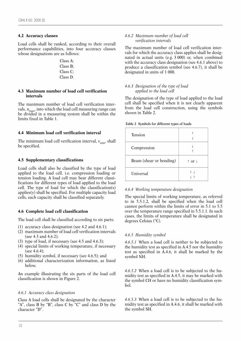
The designation of the type of load applied to the loadcell shall be specified when it is not clearly apparentfrom the load cell construction, using the symbolsshown in Table 2.
4.6.4 Working temperature designation
The special limits of working temperature, as referredto in 5.5.1.2, shall be specified when the load cellcannot perform within the limits of error in 5.1 to 5.5over the temperature range specified in 5.5.1.1. In suchcases, the limits of temperature shall be designated indegrees Celsius (°C).
4.6.5 Humidity symbol
4.6.5.1 When a load cell is neither to be subjected tothe humidity test as specified in A.4.5 nor the humiditytest as specified in A.4.6, it shall be marked by thesymbol NH.
4.6.5.2 When a load cell is to be subjected to the hu-midity test as specified in A.4.5, it may be marked withthe symbol CH or have no humidity classification sym-bol.
4.6.5.3 When a load cell is to be subjected to the hu-midity test as specified in A.4.6, it shall be marked withthe symbol SH.
Tension
Compression
Beam (shear or bending)
Universal
↑↓
↑ ↓↓ ↑
↑ or ↓
↓↑
Table 2 Symbols for different types of loads

OIML R 60: 2000 (E)
11
4.6.6 Additional information
4.6.6.1 Mandatory additional information
In addition to the information required in 4.6.1 to4.6.5, the following information shall be specified:
a) name or trademark of manufacturer;b) manufacturer’s designation or load cell model;c) serial number and year of manufacture;d) minimum dead load, Emin, maximum capacity,
Emax, safe load limit, Elim (all in units of g, kg or t,as applicable);
e) minimum load cell verification interval, vmin;f) other pertinent conditions that must be observed to
obtain the specified performance (for example, elec-trical characteristics of the load cell such as outputrating, input impedance, supply voltage, cabledetails, etc.); and
g) the value of the apportionment factor, pLC, if notequal to 0.7.
4.6.6.2 Non-mandatory additional information
In addition to the information required in 4.6.1 to4.6.6.1, the following information may optionally bespecified:
a) for a weighing instrument (for example a multiplerange instrument according to OIML R 76), therelative vmin, Y, where Y = Emax / vmin (see 2.3.14);
b) for a weighing instrument (for example a multi-interval instrument according to OIML R 76), therelative DR, Z, where Z = Emax / (2 × DR) (see 2.3.13)and the value of DR (see 2.3.9) is set at themaximum permissible minimum dead load outputreturn according to 5.3.2.
Table 4 Examples of multiple classifications
Table 3 Examples of load cell classification
4.6.8 Multiple classifications
Load cells that have complete classifications for differ-ent types of load shall be designated using separateinformation for each classification. Examples areshown in Table 4.
An illustration of the standard classification symbolsusing an example is shown in Figure 2.
4.7 Presentation of information
4.7.1 Minimum load cell markings
The following minimum amount of information, re-quired in 4.6, shall be marked on each load cell:a) name or trademark of manufacturer;b) manufacturer’s designation or load cell model;c) serial number;d) maximum capacity, Emax.
Classification Descriptionsymbol
C2 Class C, 2 000 intervals
C3 5/35 Class C, 3 000 intervals, compression, + 5 °C to + 35 °C
C2 NH Class C, 2 000 intervals, not to besubjected to humidity test
C2
C1.5
↑
↓
↓↑C1
C3
– 5/30
– 5/30
Class C, 2 000 intervals, shear beam
Class C, 1 500 intervals, bending beam
Class C, 1 000 intervals, compression,– 5 °C to + 30 °C
Class C, 3 000 intervals, tension,– 5 °C to + 30 °C
Classification symbol Description
↑↓
4.6.7 Standard classification
Standard classifications shall be used; examples areshown in Table 3.
OIML R 60: 2000 (E)
12
4.7.2 Required information not marked on load cell
If the information required in 4.6 is not marked on theload cell then it shall be provided in an accompanyingdocument provided by the manufacturer. Where such adocument is provided, the information required in4.7.1 shall also be given therein.
4.8 OIML certificate
4.8.1 Preparation of certificate
The OIML certificate shall be prepared according to therules contained within the OIML Publication OIMLCertificate System for Measuring Instruments. The for-mat of the certificate shall be as specified in Annex E,OIML Certificate of conformity for load cells.
4.8.2 Reference of values on certificate
Regardless of the evaluation result of any load cell in aload cell family, the certificate to be issued should notprovide for any characteristics or values which arebeyond those that the manufacturer has requested andfor which the manufacturer intends to guarantee, forexample, by expressing the relevant characteristics andvalues in its data sheet.
5 Maximum permissible load cell errors
5.1 Maximum permissible errors for eachaccuracy class
The maximum permissible load cell errors for eachaccuracy class (the indicated load cell output having
been adjusted to zero at minimum dead load, Emin) arerelated to the maximum number of load cell verifica-tion intervals specified for the load cell (see 4.3) and tothe actual value of the load cell verification interval, v.
5.1.1 Pattern evaluation
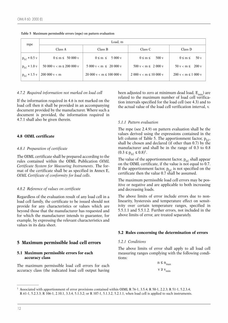
The mpe (see 2.4.9) on pattern evaluation shall be thevalues derived using the expressions contained in theleft column of Table 5. The apportionment factor, pLC,shall be chosen and declared (if other than 0.7) by themanufacturer and shall be in the range of 0.3 to 0.8(0.3 ≤ pLC ≤ 0.8)1.
The value of the apportionment factor, pLC shall appearon the OIML certificate, if the value is not equal to 0.7.If the apportionment factor, pLC is not specified on thecertificate then the value 0.7 shall be assumed.
The maximum permissible load cell errors may be pos-itive or negative and are applicable to both increasingand decreasing loads.
The above limits of error include errors due to non-linearity, hysteresis and temperature effect on sensit-ivity over certain temperature ranges, specified in5.5.1.1 and 5.5.1.2. Further errors, not included in theabove limits of error, are treated separately.
5.2 Rules concerning the determination of errors
5.2.1 Conditions
The above limits of error shall apply to all load cellmeasuring ranges complying with the following condi-tions:
n ≤ nmax
v ≥ vmin
Table 5 Maximum permissible errors (mpe) on pattern evaluation
mpeLoad, m
Class A Class B Class C Class D
pLC × 0.5 v 0 ≤ m ≤ 50 000 v 0 ≤ m ≤ 5 000 v 0 ≤ m ≤ 500 v 0 ≤ m ≤ 50 v
pLC × 1.0 v 50 000 v < m ≤ 200 000 v 5 000 v < m ≤ 20 000 v 500 v < m ≤ 2 000 v 50 v < m ≤ 200 v
pLC × 1.5 v 200 000 v < m 20 000 v < m ≤ 100 000 v 2 000 v < m ≤ 10 000 v 200 v < m ≤ 1 000 v
1 Associated with apportionment of error provisions contained within OIML R 76-1, 3.5.4; R 50-1, 2.2.3; R 51-1, 5.2.3.4; R 61-1, 5.2.3.3; R 106-1, 2.10.1, 3.3.4, 5.1.3.2; or R 107-1, 5.1.3.2, 5.2.1.1, when load cell is applied to such instruments.
OIML R 60: 2000 (E)
13
5.2.2 Limits of error
The above limits of error shall refer to the error envel-ope defined in 1.2 and 5.1 which is referenced to thestraight line that passes through the minimum loadoutput and the load cell output for a load of 75 % of themeasuring range taken on ascending load at 20 °C. Thisis based upon the initial 20 °C load test. See C.2.2.
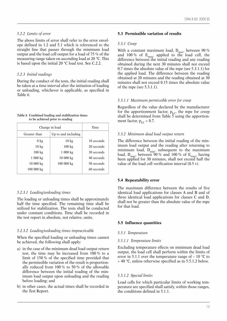
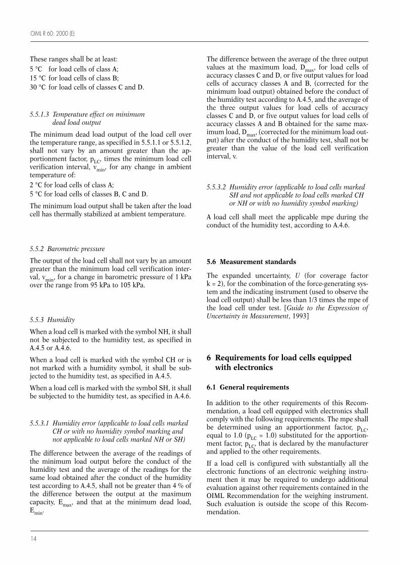
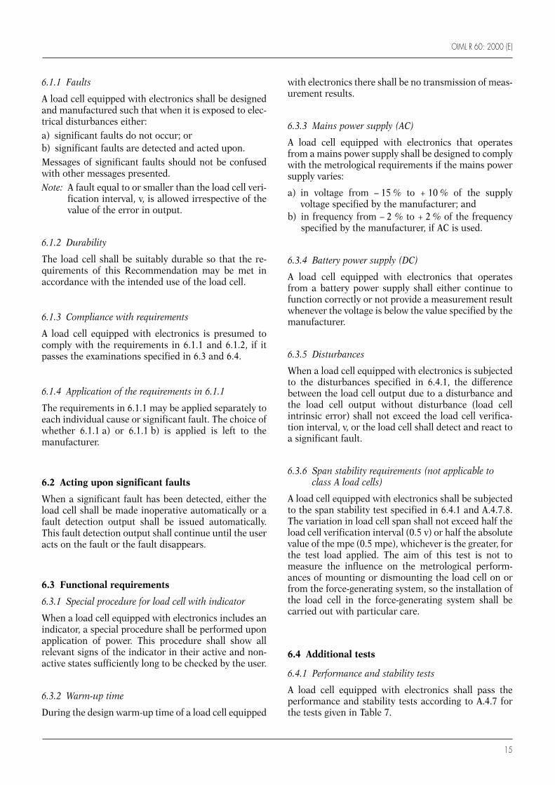
5.2.3 Initial readings
During the conduct of the tests, the initial reading shallbe taken at a time interval after the initiation of loadingor unloading, whichever is applicable, as specified inTable 6.
5.2.3.1 Loading/unloading times
The loading or unloading times shall be approximatelyhalf the time specified. The remaining time shall beutilized for stabilization. The tests shall be conductedunder constant conditions. Time shall be recorded inthe test report in absolute, not relative, units.
5.2.3.2 Loading/unloading times impracticable
When the specified loading or unloading times cannotbe achieved, the following shall apply:
a) in the case of the minimum dead load output returntest, the time may be increased from 100 % to alimit of 150 % of the specified time provided thatthe permissible variation of the result is proportion-ally reduced from 100 % to 50 % of the allowabledifference between the initial reading of the min-imum load output upon unloading and the readingbefore loading; and
b) in other cases, the actual times shall be recorded inthe Test Report.
5.3 Permissible variation of results
5.3.1 Creep
With a constant maximum load, Dmax, between 90 %and 100 % of Emax, applied to the load cell, thedifference between the initial reading and any readingobtained during the next 30 minutes shall not exceed0.7 times the absolute value of the mpe (see 5.3.1.1) forthe applied load. The difference between the readingobtained at 20 minutes and the reading obtained at 30minutes shall not exceed 0.15 times the absolute valueof the mpe (see 5.3.1.1).
5.3.1.1 Maximum permissible error for creep
Regardless of the value declared by the manufacturerfor the apportionment factor, pLC, the mpe for creepshall be determined from Table 5 using the apportion-ment factor, pLC = 0.7.
5.3.2 Minimum dead load output return
The difference between the initial reading of the min-imum load output and the reading after returning tominimum load, Dmin, subsequent to the maximumload, Dmax, between 90 % and 100 % of Emax, havingbeen applied for 30 minutes, shall not exceed half thevalue of the load cell verification interval (0.5 v).
5.4 Repeatability error
The maximum difference between the results of fiveidentical load applications for classes A and B and ofthree identical load applications for classes C and D,shall not be greater than the absolute value of the mpefor that load.
5.5 Influence quantities
5.5.1 Temperature
5.5.1.1 Temperature limits
Excluding temperature effects on minimum dead loadoutput, the load cell shall perform within the limits oferror in 5.1.1 over the temperature range of – 10 °C to+ 40 °C, unless otherwise specified as in 5.5.1.2 below.
5.5.1.2 Special limits
Load cells for which particular limits of working tem-perature are specified shall satisfy, within those ranges,the conditions defined in 5.1.1.
Change in load Time
Greater than Up to and including
0 kg 10 kg 10 seconds
10 kg 100 kg 20 seconds
100 kg 1 000 kg 30 seconds
1 000 kg 10 000 kg 40 seconds
10 000 kg 100 000 kg 50 seconds
100 000 kg 60 seconds
Table 6 Combined loading and stabilization times to be achieved prior to reading
OIML R 60: 2000 (E)
14
These ranges shall be at least:5 °C for load cells of class A;15 °C for load cells of class B;30 °C for load cells of classes C and D.
5.5.1.3 Temperature effect on minimum dead load output
The minimum dead load output of the load cell overthe temperature range, as specified in 5.5.1.1 or 5.5.1.2,shall not vary by an amount greater than the ap-portionment factor, pLC, times the minimum load cellverification interval, vmin, for any change in ambienttemperature of:2 °C for load cells of class A;5 °C for load cells of classes B, C and D.
The minimum load output shall be taken after the loadcell has thermally stabilized at ambient temperature.
5.5.2 Barometric pressure
The output of the load cell shall not vary by an amountgreater than the minimum load cell verification inter-val, vmin, for a change in barometric pressure of 1 kPaover the range from 95 kPa to 105 kPa.
5.5.3 Humidity
When a load cell is marked with the symbol NH, it shallnot be subjected to the humidity test, as specified inA.4.5 or A.4.6.
When a load cell is marked with the symbol CH or isnot marked with a humidity symbol, it shall be sub-jected to the humidity test, as specified in A.4.5.
When a load cell is marked with the symbol SH, it shallbe subjected to the humidity test, as specified in A.4.6.
5.5.3.1 Humidity error (applicable to load cells markedCH or with no humidity symbol marking and not applicable to load cells marked NH or SH)
The difference between the average of the readings ofthe minimum load output before the conduct of thehumidity test and the average of the readings for thesame load obtained after the conduct of the humiditytest according to A.4.5, shall not be greater than 4 % ofthe difference between the output at the maximumcapacity, Emax, and that at the minimum dead load,Emin.
The difference between the average of the three outputvalues at the maximum load, Dmax, for load cells ofaccuracy classes C and D, or five output values for loadcells of accuracy classes A and B, (corrected for theminimum load output) obtained before the conduct ofthe humidity test according to A.4.5, and the average ofthe three output values for load cells of accuracyclasses C and D, or five output values for load cells ofaccuracy classes A and B obtained for the same max-imum load, Dmax, (corrected for the minimum load out-put) after the conduct of the humidity test, shall not begreater than the value of the load cell verificationinterval, v.
5.5.3.2 Humidity error (applicable to load cells markedSH and not applicable to load cells marked CHor NH or with no humidity symbol marking)
A load cell shall meet the applicable mpe during theconduct of the humidity test, according to A.4.6.
5.6 Measurement standards
The expanded uncertainty, U (for coverage factork = 2), for the combination of the force-generating sys-tem and the indicating instrument (used to observe theload cell output) shall be less than 1/3 times the mpe ofthe load cell under test. [Guide to the Expression ofUncertainty in Measurement, 1993]
6 Requirements for load cells equippedwith electronics
6.1 General requirements
In addition to the other requirements of this Recom-mendation, a load cell equipped with electronics shallcomply with the following requirements. The mpe shallbe determined using an apportionment factor, pLC,equal to 1.0 (pLC = 1.0) substituted for the apportion-ment factor, pLC, that is declared by the manufacturerand applied to the other requirements.
If a load cell is configured with substantially all theelectronic functions of an electronic weighing instru-ment then it may be required to undergo additionalevaluation against other requirements contained in theOIML Recommendation for the weighing instrument.Such evaluation is outside the scope of this Recom-mendation.
OIML R 60: 2000 (E)
15
6.1.1 Faults
A load cell equipped with electronics shall be designedand manufactured such that when it is exposed to elec-trical disturbances either:a) significant faults do not occur; orb) significant faults are detected and acted upon. Messages of significant faults should not be confusedwith other messages presented.Note: A fault equal to or smaller than the load cell veri-
fication interval, v, is allowed irrespective of thevalue of the error in output.
6.1.2 Durability
The load cell shall be suitably durable so that the re-quirements of this Recommendation may be met inaccordance with the intended use of the load cell.
6.1.3 Compliance with requirements
A load cell equipped with electronics is presumed tocomply with the requirements in 6.1.1 and 6.1.2, if itpasses the examinations specified in 6.3 and 6.4.
6.1.4 Application of the requirements in 6.1.1
The requirements in 6.1.1 may be applied separately toeach individual cause or significant fault. The choice ofwhether 6.1.1 a) or 6.1.1 b) is applied is left to themanufacturer.
6.2 Acting upon significant faults
When a significant fault has been detected, either theload cell shall be made inoperative automatically or afault detection output shall be issued automatically.This fault detection output shall continue until the useracts on the fault or the fault disappears.
6.3 Functional requirements
6.3.1 Special procedure for load cell with indicator
When a load cell equipped with electronics includes anindicator, a special procedure shall be performed uponapplication of power. This procedure shall show allrelevant signs of the indicator in their active and non-active states sufficiently long to be checked by the user.
6.3.2 Warm-up time
During the design warm-up time of a load cell equipped
with electronics there shall be no transmission of meas-urement results.
6.3.3 Mains power supply (AC)
A load cell equipped with electronics that operatesfrom a mains power supply shall be designed to complywith the metrological requirements if the mains powersupply varies:
a) in voltage from – 15 % to + 10 % of the supplyvoltage specified by the manufacturer; and
b) in frequency from – 2 % to + 2 % of the frequencyspecified by the manufacturer, if AC is used.
6.3.4 Battery power supply (DC)
A load cell equipped with electronics that operatesfrom a battery power supply shall either continue tofunction correctly or not provide a measurement resultwhenever the voltage is below the value specified by themanufacturer.
6.3.5 Disturbances
When a load cell equipped with electronics is subjectedto the disturbances specified in 6.4.1, the differencebetween the load cell output due to a disturbance andthe load cell output without disturbance (load cellintrinsic error) shall not exceed the load cell verifica-tion interval, v, or the load cell shall detect and react toa significant fault.
6.3.6 Span stability requirements (not applicable toclass A load cells)
A load cell equipped with electronics shall be subjectedto the span stability test specified in 6.4.1 and A.4.7.8.The variation in load cell span shall not exceed half theload cell verification interval (0.5 v) or half the absolutevalue of the mpe (0.5 mpe), whichever is the greater, forthe test load applied. The aim of this test is not tomeasure the influence on the metrological perform-ances of mounting or dismounting the load cell on orfrom the force-generating system, so the installation ofthe load cell in the force-generating system shall becarried out with particular care.
6.4 Additional tests
6.4.1 Performance and stability tests
A load cell equipped with electronics shall pass theperformance and stability tests according to A.4.7 forthe tests given in Table 7.

OIML R 60: 2000 (E)
16
Generally, the tests are carried out on fully operationalequipment in its normal state or in a status as similaras possible thereto. If the load cell is equipped with aninterface that permits it to be coupled to externalequipment, all functions that are performed or initi-ated via an interface shall operate correctly.
7 Metrological controls
7.1 Liability to legal metrological controls
7.1.1 Imposition of controls
This Recommendation prescribes performance require-ments for load cells used in the measurement of mass.National legislation may impose metrological controlsthat verify compliance with this Recommendation. Suchcontrols, when imposed, may include pattern evalua-tion.
7.2 Test requirements
Test procedures for the pattern evaluation of load cellsare provided in Annex A and the Test Report Format isprovided in Annexes C and D. Initial and subsequentverification of load cells independent of the measuringsystem in which they are used is normally consideredinappropriate if the complete system performance isverified by other means.
7.3 Selection of load cells within a family
Where a family composed of one or more groups ofload cells of various capacities and characteristics ispresented for pattern evaluation, the following provi-sions shall apply.
7.3.1 Number of load cells to be tested
The selection of load cells to be tested shall be such thatthe number of load cells to be tested is minimized (seepractical example in Annex B).
7.3.2 Load cells of the same capacity belonging to different groups
Where load cells of the same capacity belong to differ-ent groups, approval of the load cell with the bestmetrological characteristics implies approval of theload cells with the lesser characteristics. Therefore,when a choice exists, the load cells with the best metro-logical characteristics shall be selected for test.
7.3.3 Load cells with a capacity in between the capacities tested
Load cells with a capacity in between the capacitiestested, as well as those above the largest capacity tested,but not over 5 times above the largest capacity tested,are deemed to be approved.
7.3.4 Smallest capacity load cell from the group
For any family, the smallest capacity load cell from thegroup with the best characteristics shall be selected fortesting. For any group, the smallest capacity load cell inthe group shall always be selected for test unless thatcapacity falls within the range of allowed capacities ofselected load cells having better metrological charac-teristics according to the requirements of 7.3.2 and7.3.3.
7.3.5 Ratio of largest capacity to the nearest smaller capacity
When the ratio of the largest capacity load cell in eachgroup to the nearest smaller capacity having been
Table 7 Performance and stability tests for a load cell equipped with electronics
Test Annex A pLCCharacteristic
test procedure under test
Warm-up time A.4.7.2 1.0 Influence factorPower voltage variations A.4.7.3 1.0 Influence factorShort-time power reductions A.4.7.4 1.0 DisturbanceBursts (electrical fast transients) A.4.7.5 1.0 DisturbanceElectrostatic discharge A.4.7.6 1.0 DisturbanceElectromagnetic susceptibility A.4.7.7 1.0 DisturbanceSpan stability A.4.7.8 1.0 Influence factor

OIML R 60: 2000 (E)
17
selected for test is greater than 5, then another load cellshall be selected. The selected load cell shall have acapacity between 5 and 10 times that of the nearestsmaller capacity load cell which has been selected.When no capacity meets this criterion, the selectedload cell shall be that having the smallest capacityexceeding 10 times that of the nearest smaller capacityload cell which has been selected.
7.3.6 Humidity test
If more than one load cell of a family has been submit-ted for testing, only one cell shall be tested for humiditywhen applicable, and only one cell shall be subjected tothe additional tests for load cells equipped with elec-tronics when applicable, that being the load cell withthe most severe characteristics (for example, thegreatest value of nmax or the lowest value of vmin).

OIML R 60: 2000 (E)
18
A.1 Scope
This Annex provides test procedures for pattern evalu-ation testing of load cells used in the measurement ofmass.
A.1.1 Wherever possible test procedures have beenestablished to apply as broadly as possible to all loadcells within the scope of OIML R 60.
A.1.2 The procedures apply to the testing of load cellsonly. No attempt has been made to cover testing ofcomplete systems that include load cells.
A.2 Purpose
The following test procedures for quantitative deter-mination of load cell performance characteristics areestablished to ensure uniform pattern evaluation.
A.3 Test conditions
A.3.1 Test equipment
The basic equipment for pattern evaluation tests con-sists of a force-generating system and a suitable linearinstrument, which measures the output of the load cell(see 5.6).
A.3.2 General considerations for environmental and test conditions
Before adequate testing and evaluation of a load cellcan be performed, careful attention shall be paid to theenvironmental and test conditions under which suchevaluations are to be made. Significant discrepanciesare frequently a result of insufficient recognition ofsuch details. The following shall be thoroughly con-sidered prior to any pattern evaluation testing pro-gram.
Annex A
(Mandatory)
Test procedures for pattern evaluation
A.3.2.1 Acceleration of gravity
The mass standards used in testing shall be corrected,if necessary, for the site of testing and the value of thegravity constant, g, at the test site shall be recordedwith the test results. The value of the mass standardsused to generate the force shall be traceable to thenational standard of mass.
A.3.2.2 Environmental conditions
Tests shall be performed under stable environmentalconditions. The ambient temperature is deemed to bestable when the difference between extreme temper-atures noted during the test does not exceed one fifth ofthe temperature range of the load cell under test, with-out being greater than 2 °C.
A.3.2.3 Loading conditions
Particular attention shall be paid to loading conditionsto prevent the introduction of errors not inherent to theload cell. Factors such as surface roughness, flatness,corrosion, scratches, eccentricity, etc., should be takeninto consideration. Loading conditions shall be inaccordance with the requirements of the load cellmanufacturer. The loads shall be applied and removedalong the sensitive axis of the load cell without intro-ducing shock to the load cell.
A.3.2.4 Measuring range limits
The minimum load, Dmin, (hereafter referred to as“minimum test load”) shall be as near as possible to butnot less than the minimum dead load, Emin, aspermitted by the force-generating system. The max-imum load, Dmax, (hereafter referred to as “maximumtest load”) shall be not less than 90 % of Emax, nor shallit be greater than Emax (refer to Fig. 1).
A.3.2.5 Reference standards
Periodic (depending on use) verification of standardsshall be made.

OIML R 60: 2000 (E)
19
A.3.2.6 Stabilization period
A stabilization period for the load cell under test andthe indicating instrument shall be provided, as recom-mended by the manufacturers of the equipment used.
A.3.2.7 Temperature conditions
It is important to allow sufficient time for temperaturestabilization of the load cell to be achieved. Particularattention shall be devoted to this requirement for largeload cells. The loading system shall be of a designwhich will not introduce significant thermal gradientswithin the load cell. The load cell and its connectingmeans (cables, tubes, etc.) which are integral or conti-guous shall be at the same test temperature. The indi-cating instrument shall be maintained at room temper-ature. The temperature effect on auxiliary connectingmeans shall be considered in determining results.
A.3.2.8 Barometric pressure effects
Where changes in barometric pressure may signifi-cantly affect the load cell output, such changes shall beconsidered.
A.3.2.9 Stability of loading means
An indicating instrument and a loading means shall beused which will provide sufficient stability to permitreadings within the limits specified in 5.6.
A.3.2.10 Indicating instrument checking
Some indicating instruments are provided with a con-venient means for checking the indicating instrumentitself. When such features are provided, they shall beutilized frequently to ensure that the indicating instru-ment is within the accuracy required by the test beingperformed. Periodic verification of the indicating in-strument calibration shall also be performed.
A.3.2.11 Other conditions
Other conditions specified by the manufacturer such asinput/output voltage, electrical sensitivity, etc. shall betaken into consideration during the test.
A.3.2.12 Time and date data
All time and date points shall be recorded such that thedata can later be presented in test reports in absolute,
not relative, units of local time and date. The date shallbe recorded in the ISO 8601 format of ccyy-mm-dd.Note: “cc” may be omitted in cases where there is no
possible confusion as to the century.
A.3.2.13 Span stability
The installation of the load cell in the force-generatingsystem shall be done with particular care, since the aimof this test is not to measure the influence on the met-rological performances of mounting/dismounting theload cell on/from the force-generating system.
A.4 Test procedures
Each of the tests below is presented as a “stand alone”individual test. However, for the efficient conduct ofthe load cell tests, it is acceptable that the increasingand decreasing load, creep, and minimum dead loadoutput return tests be conducted at the given test temp-erature before changing to the next test temperature(see A.5, Figures A.1 and A.2). The barometric pressureand the humidity tests are conducted individually fol-lowing completion of the above tests.
A.4.1 Determination of load cell error,repeatability error and temperature effecton minimum dead load output
A.4.1.1 Check test conditions
Refer to the test conditions in A.3 to ensure that properconsideration has been given to those conditions, priorto performing the following tests.
A.4.1.2 Insert load cell
Insert the load cell into the force-generating system,load to the minimum test load, Dmin, and stabilize at20 °C.
A.4.1.3 Exercise load cell
Exercise the load cell by applying the maximum testload, Dmax, three times, returning to the minimum testload, Dmin, after each load application. Wait 5 minutes.
A.4.1.4 Check indicating instrument
Check the indicating instrument according to A.3.2.10.

OIML R 60: 2000 (E)
20
A.4.1.5 Monitor load cell
Monitor the minimum test load output until stable.
A.4.1.6 Record indication
Record the indicating instrument indication at theminimum test load, Dmin.
A.4.1.7 Test load points
All test load points in a loading and unloading se-quence shall be spaced at approximately equal timeintervals. The readings shall be taken at time intervalsas near as possible to those specified in Table 6 in 5.2.3.These two time intervals shall be recorded.
A.4.1.8 Apply loads
Apply increasing loads up to the maximum test load,Dmax. There shall be at least five increasing load points,which shall include loads approximating to the highestvalues in the applicable steps of maximum permissibleload cell errors, as listed in Table 5 in 5.1.1.
A.4.1.9 Record indications
Record the indicating instrument indications at timeintervals as near as possible to those specified inTable 6 in 5.2.3. These two time intervals shall be re-corded.
A.4.1.10 Decrease test loads
Decrease the test loads to the minimum test load, Dmin,using the same load points as described in A.4.1.8.
A.4.1.11 Record indications
Record the indicating instrument indications at timeintervals as near as possible to those specified inTable 6 in 5.2.3. These two time intervals shall berecorded.
A.4.1.12 Repeat procedures for different accuracy classes
Repeat the operations described in A.4.1.7 to A.4.1.11four more times for accuracy classes A and B or twomore times for accuracy classes C and D.
A.4.1.13 Repeat procedures for different temperatures
Repeat the operations described in A.4.1.3 to A.4.1.12,first at the higher temperature, then at the lower temp-erature, including the approximate temperature rangelimits for the accuracy class intended; then perform theoperations in A.4.1.3 to A.4.1.12 at 20 °C.
A.4.1.14 Determine magnitude of load cell error
The magnitude of the load cell error shall be deter-mined based on the average of the results of the testsconducted at each temperature level and comparedwith the maximum permissible load cell errors in 5.1.1.
A.4.1.15 Determine repeatability error
From the resulting data, the repeatability error may bedetermined and compared with the limits specified in5.4.
A.4.1.16 Determine temperature effect on minimum dead load output
From the resulting data, the temperature effect on min-imum dead load output may be determined andcompared with the limits specified in 5.5.1.3.
A.4.2 Determination of creep error
A.4.2.1 Check test conditions
Refer to the test conditions in A.3 to ensure that properconsideration has been given to those conditions priorto performing the following tests.
A.4.2.2 Insert load cell
Insert the load cell into the force-generating system,load to the minimum test load, Dmin, and stabilize at20 °C.
A.4.2.3 Exercise load cell
Exercise the load cell by applying the maximum testload, Dmax, three times, returning to the minimum testload, Dmin, after each load application. Wait one hour.
OIML R 60: 2000 (E)
21
A.4.2.4 Check indicating instrument
Check the indicating instrument according to A.3.2.10.
A.4.2.5 Monitor load cell
Monitor the minimum test load output until stable.
A.4.2.6 Record indication
Record the indicating instrument indication at theminimum test load, Dmin.
A.4.2.7 Apply load
Apply a constant maximum test load, Dmax.
A.4.2.8 Record indications
Record the initial indicating instrument indication atthe time intervals specified in Table 6 in 5.2.3. Continueto record periodically thereafter, at recorded time inter-vals over a 30-minute period, ensuring that a reading istaken at 20 minutes.
A.4.2.9 Repeat procedures for different temperatures
Repeat the operations described in A.4.2.3 to A.4.2.8,first at the higher temperature, then at the lower temp-erature, including the approximate temperature rangelimits for the accuracy class intended.
A.4.2.10 Determine creep error
With the resulting data, and taking into account theeffect of barometric pressure changes according toA.3.2.8, the magnitude of the creep error can be deter-mined and compared with the permissible variationspecified in 5.3.1.
A.4.3 Determination of minimum dead load output return (DR)
A.4.3.1 Check test conditions
Refer to the test conditions in A.3 to ensure that properconsideration has been given to those conditions priorto performing the following test.
A.4.3.2 Insert load cell
Insert the load cell into the force-generating system,load to the minimum test load, Dmin, and stabilize at20 °C.
A.4.3.3 Exercise load cell
Exercise the load cell by applying the maximum testload, Dmax, three times, returning to the minimum testload, Dmin, after each load application. Wait one hour.
A.4.3.4 Check indicating instrument
Check the indicating instrument according to A.3.2.10.
A.4.3.5 Monitor load cell
Monitor the minimum test load output until stable.
A.4.3.6 Record indication
Record the indicating instrument indication at theminimum test load, Dmin.
A.4.3.7 Apply load
Apply a constant maximum test load, Dmax.
A.4.3.8 Record indications
Record the initial indicating instrument indication attime intervals as near as possible to those specified inTable 6 in 5.2.3. These two time intervals shall berecorded. Record the time at which the load is fullyapplied and maintain the load for a 30-minute period.
A.4.3.9 Record data
Record the time of initiation of unloading and return tothe minimum test load, Dmin.
A.4.3.10 Record indication
Record the indicating instrument indication at timeintervals as near as possible to those specified inTable 6 in 5.2.3. These two time intervals shall be re-corded.
OIML R 60: 2000 (E)
22
A.4.3.11 Repeat procedures for different temperatures
Repeat the operations described in A.4.3.3 to A.4.3.10,first at the higher temperature, then at the lower temp-erature, including the approximate temperature rangelimits for the accuracy class intended.
A.4.3.12 Determine minimum dead load output return (DR)
With the resulting data, the magnitude of the minimumdead load output return (DR) can be determined andcompared with the permissible variation specified in5.3.2.
A.4.4 Determination of barometric pressure effects
This test shall be conducted unless there is sufficientdesign justification to show that the load cell perform-ance is not affected by changes in barometric pressure.
A.4.4.1 Check test conditions
Refer to the test conditions in A.3 to ensure that properconsideration has been given to those conditions priorto performing the following test.
A.4.4.2 Insert load cell
At room temperature, insert the unloaded load cell intothe pressure chamber at atmospheric pressure.
A.4.4.3 Check indicating instrument
Check the indicating instrument according to A.3.2.10.
A.4.4.4 Monitor load cell
Monitor the output until stable.
A.4.4.5 Record indication
Record the indicating instrument indication.
A.4.4.6 Change barometric pressure
Change the barometric pressure to a value of approx-imately 1 kPa lower or higher than atmospheric pres-sure and record the indicating instrument indication.
A.4.4.7 Determine barometric pressure error
With the resulting data, the magnitude of the baro-metric pressure influence can be determined and com-pared with the limits specified in 5.5.2.
A.4.5 Determination of humidity effectsfor load cells marked CH or not marked
A.4.5.1 Check test conditions
Refer to the test conditions in A.3 to ensure that properconsideration has been given to those conditions priorto performing the following test.
A.4.5.2 Insert load cell
Insert the load cell into the force-generating system,load to the minimum test load, Dmin, and stabilize at20 °C.
A.4.5.3 Exercise load cell
Exercise the load cell by applying the maximum testload, Dmax, three times, returning to the minimum testload, Dmin, after each application.
A.4.5.4 Check indicating instrument
Check the indicating instrument according to A.3.2.10.
A.4.5.5 Monitor load cell
Monitor the minimum test load output until stable.
A.4.5.6 Record indication
Record the indicating instrument indication at theminimum test load, Dmin.
A.4.5.7 Apply load
Apply a maximum test load, Dmax.
A.4.5.8 Record indications
Record the initial indicating instrument indication attime intervals as near as possible to those specified in

OIML R 60: 2000 (E)
23
Table 6 in 5.2.3. These two time intervals shall be re-corded.
A.4.5.9 Remove load
Remove the test load to the minimum test load, Dmin.
A.4.5.10 Record indication
Record the indicating instrument indication at timeintervals as near as possible to those specified inTable 6 in 5.2.3. These two time intervals shall be re-corded.
A.4.5.11 Repeat procedures for different accuracy classes
Repeat the operations described in A.4.5.7 to A.4.5.10four more times for accuracy classes A and B or twomore times for accuracy classes C and D.
A.4.5.12 Conduct damp heat, cyclic test
Conduct a damp heat, cyclic test in accordance withIEC 60068-2-30 (1980-01) Environmental testing -Part 2: Tests. Test Db and guidance: Damp heat cyclic(12 + 12-hour cycle) as amended by IEC 60068-2-30-am1 (1985-01). Background information concerningdamp heat, cyclic tests is given in IEC 60068-2-28(1990-03) Environmental testing - Part 2: Tests. Guid-ance for damp heat tests.
Test procedure in brief:
This test consists of exposure to 12 temperature cyclesof 24-hour duration each. The relative humidity isbetween 80 % and 96 % and the temperature is variedfrom 25 °C to 40 °C, in accordance with the specifiedcycle.
Test severity:
40 °C, 12 cycles.
Initial measurements:
According to A.4.5.1 to A.4.5.11 above.
State of load cell during conditioning:
Load cell placed in the chamber with the output con-nection external to the chamber, and switched off. Usevariant 2 of IEC 60068-2-30 (1980-01) as amended by
IEC 60068-2-30-am1 (1985-01) when lowering thetemperature.
Recovery conditions and final measurements:
According to A.4.5.13 below.
A.4.5.13 Remove load cell from chamber
Remove the load cell from the humidity chamber, care-fully remove surface moisture, and maintain the loadcell at standard atmospheric conditions for a periodsufficient to attain temperature stability (normally 1 to2 hours).
Repeat A.4.5.1 to A.4.5.11 ensuring that the minimumtest load, Dmin, and the maximum test load, Dmax, ap-plied are the same as previously used.
A.4.5.14 Determine the magnitude of humidity-induced variations
With the resulting data, the magnitude of humidity-induced variations can be determined and comparedwith the limits specified in 5.5.3.1.
A.4.6 Determination of humidity effectsfor load cells marked SH
A.4.6.1 Check test conditions
Refer to the test conditions in A.3 to ensure that properconsideration has been given to those conditions priorto performing the following tests.
A.4.6.2 Insert load cell
Insert the load cell into the force-generating system,load to the minimum test load, Dmin, and stabilize at20 °C.
A.4.6.3 Exercise load cell
Exercise the load cell by applying the maximum testload, Dmax, three times, returning to the minimum testload, Dmin, after each load application.
A.4.6.4 Check indicating instrument
Check the indicating instrument according to A.3.2.10.

OIML R 60: 2000 (E)
24
A.4.6.5 Monitor load cell
Monitor the minimum test load output until stable.
A.4.6.6 Record indication
Record the indicating instrument indication at theminimum test load, Dmin.
A.4.6.7 Test load points
All test load points in a loading and unloading se-quence shall be spaced at approximately equal timeintervals. The readings shall be taken at time intervalsas near as possible to those specified in Table 6 in 5.2.3.These two time intervals shall be recorded.
A.4.6.8 Apply loads
Apply increasing loads up to the maximum test load,Dmax. There shall be at least five increasing load pointswhich shall include loads approximating to the highestvalues in the applicable steps of maximum permissibleload cell errors, as listed in Table 5 in 5.1.1.
A.4.6.9 Record indications
Record the indicating instrument indications at timeintervals as near as possible to those specified inTable 6 in 5.2.3. These two time intervals shall be re-corded.
A.4.6.10 Decrease load
Decrease the test load to the minimum test load, Dmin,using the same load points as described in A.4.6.8.
A.4.6.11 Conduct damp heat, steady state test
Conduct a damp heat, steady state test in accordancewith IEC 60068-2-3 (1969-01) Environmental testing -Part 2: Tests. Test Ca: Damp heat, steady state, IEC60068-2-56 (1988-12) Environmental testing - Part 2:Tests. Test Cb: Damp heat, steady state, primarily forequipment and IEC 60068-2-28 (1990-03) Environ-mental testing - Part 2: Tests. Guidance for damp heattests.
Test procedure in brief:
This test involves exposure of the load cell to a constanttemperature and a constant relative humidity. The loadcell shall be tested as specified in A.4.6.1 to A.4.6.10:
a) at a reference temperature (20 °C or the mean valueof the temperature range whenever 20 °C is outsidethis range) and a relative humidity of 50 % follow-ing conditioning;
b) at the high temperature of the range specified in5.5.1 for the load cell and a relative humidity of85 %, two days following temperature and humiditystabilization; and
c) at the reference temperature and relative humidityof 50 %.
State of load cell during conditioning:
Place the load cell in the chamber with the outputconnection external to the chamber, and switched on.Use IEC 60068-2-3 (1969-01) and IEC 60068-2-56(1988-12) when lowering the temperature.
A.4.6.12 Recording indications
Record the indicating instrument indications at timeintervals as near as possible to those specified inTable 6 in 5.2.3. These two time intervals shall be re-corded.
A.4.6.13 Determine the magnitude of humidity-induced variations
With the resulting data, the magnitude of humidity-induced variations can be determined and comparedwith the limits specified in 5.5.3.2.
A.4.7 Additional tests for load cells equipped with electronics
A.4.7.1 Evaluation of error for load cells with digital output interval
For load cells possessing a digital output interval greaterthan 0.20 v, the changeover points are to be used in theevaluation of errors, prior to rounding as follows.
At a certain load, L, the digital output value, I, is noted.Additional loads, for example 0.1 v, are successivelyadded until the output of the load cell is increasedunambiguously by one digital output increment (I + v).The additional amount of load, ∆L, added to the loadcell gives the digital output value prior to rounding, P,by using the following formula:

OIML R 60: 2000 (E)
25
P = I + 1/2 v – ∆L
where:I = the indication or digital output value;v = the load cell verification interval; and∆L = additional load added to the load cell.
The error, E, prior to rounding is:
E = P – L = I + 1/2 v – ∆L – Land the corrected error, Ec, prior to rounding is:
Ec = E – Eo ≤ mpe
where Eo is the error calculated at the minimum testload, Dmin.
A.4.7.2 Warm-up time (see 6.3.2)
Test procedure in brief:
Stabilize the load cell at 20 °C and disconnect from anyelectrical supply for a period of at least 8 hours prior tothe test.
Insert the load cell into the force-generating system.
Exercise the load cell by applying a maximum test load,Dmax, three times, returning to the minimum test load,Dmin, after each load application.
Allow the load cell to rest for 5 minutes.
Connect the load cell to the power supply and switchon.
Record data:
As soon as a measurement result can be obtained,record the minimum test load output and the max-imum test load, Dmax, applied.
Loading and unloading:
The maximum test load output shall be determined attime intervals as close as possible to those specified inTable 6 in 5.2.3 and recorded and the load should bereturned to the minimum test load, Dmin. These meas-urements shall be repeated after 5, 15 and 30 minutes.
Maximum allowable variations:
The absolute value of the difference between the indi-cation at the maximum test load, Dmax, and that at theminimum test load, Dmin, taken immediately prior tothe application of the maximum test load, Dmax, in thecase of any of the individual measurements shall notexceed the absolute value of the mpe for the maximum
test load, Dmax, applied.
For load cells of class A, the provisions of the operatingmanual for the time following connection to electricalsupply shall be observed.
A.4.7.3 Power voltage variations (see 6.3.3 and 6.3.4)
Test procedure in brief:
This test consists of subjecting the load cell to varia-tions of power voltage.
A load test is performed in accordance with A.4.1.1 toA.4.1.12 at 20 °C, with the load cell powered at refer-ence voltage. The test is repeated with the load cellpowered at the upper limit and at the lower limit ofpower voltage.
Before any test:
Stabilize the load cell under constant environmentalconditions.
Test severity:
Mains power voltage variations:
a) upper voltage limit (V + 10 %);b) lower voltage limit (V – 15 %).
Battery power voltage variations:
a) upper voltage limit (not applicable);b) lower voltage limit (specified by the manufacturer,
below V).
The voltage, V, is the value specified by the manu-facturer. If a range of reference mains power voltage(Vmin, Vmax) is specified, then the test shall be per-formed at an upper voltage limit of Vmax and a lowervoltage limit of Vmin.
Maximum allowable variations:
All functions shall operate as designed.
All measurement results shall be within maximumpermissible errors.
Note: Where a load cell is powered by a three-phasesupply, the voltage variations shall apply to eachphase successively and all phases simultaneous-ly.
OIML R 60: 2000 (E)
26
Reference to IEC Publication:
IEC Publication 61000-4-11 (1994-06) Electro-magnetic compatibility (EMC) - Part 4: Testing andmeasurement techniques – Section 11: Voltage dips,short interruptions and voltage variations immunitytests. Section 5.2 (Test levels – voltage variation),Section 8.2.2 (Execution of the test – voltage variation).
A.4.7.4 Short-time power reductions (see 6.3.5)
Test procedure in brief:
This test consists of exposing the load cell to specifiedshort-time power reductions.
A test generator capable of reducing the amplitude ofone or more half cycles (at zero crossings) of the ACmains voltage shall be used. The test generator shall beadjusted before connecting to the load cell. The mainsvoltage reductions shall be repeated ten times at inter-vals of at least 10 seconds.
Test load:
During the test, the effect of any automatic zero-settingor zero-tracking features shall be switched off or sup-pressed, for example by applying a small test load. Thetest load need not be greater than necessary to ac-complish this suppression.
Before any test:
Stabilize the load cell under constant environmentalconditions.
Test severity:
Reduction: 100 % 50 %Number of half cycles: 1 2
Maximum allowable variations:
The difference between the measurement result due tothe disturbance and the measurement result withoutthe disturbance shall not exceed one minimum loadcell verification interval, vmin, or the load cell shalldetect and react to a significant fault.
Reference to IEC Publication:
IEC Publication 61000-4-11 (1994-06) Electro-magnetic compatibility (EMC) - Part 4: Testing and
measurement techniques – Section 11: Voltage dips,short interruptions and voltage variations immunitytests. Section 5.1 (Test levels – voltage dips and shortinterruptions), Section 8.2.1 (Execution of the test –voltage dips and short interruptions).
A.4.7.5 Bursts (electrical fast transients) (see 6.3.5)
Test procedure in brief:
This test consists of exposing the load cell to specifiedbursts of voltage spikes.
Test instrumentation:
In accordance with IEC 61000-4-4 (1995-01), No. 6.
Test set-up:
In accordance with IEC 61000-4-4 (1995-01), No. 7.
Test procedure:
In accordance with IEC 61000-4-4 (1995-01), No. 8.
Before any test:
Stabilize the load cell under constant environmentalconditions.
The test shall be applied separately to:
a) power supply lines;b) I/O circuits and communication lines, if any.
Test load:
During the test, the effect of any automatic zero-settingor zero-tracking features shall be switched off or sup-pressed, for example by applying a small test load. Thetest load need not be greater than necessary to ac-complish this suppression.
Test severity:
Level 2 (in accordance with IEC 61000-4-4 (1995-01),No. 5).
Open circuit output test voltage for:
• power supply lines: 1 kV;• I/O signal, data, and control lines: 0.5 kV.

OIML R 60: 2000 (E)
27
Maximum allowable variations:
The difference between the measurement result due tothe disturbance and the measurement result withoutthe disturbance shall not exceed one minimum loadcell verification interval, vmin, or the load cell shalldetect and react to a significant fault.
Reference to IEC Publication:
IEC Publication 61000-4-4 (1995-01) Electromagneticcompatibility (EMC) - Part 4: Testing and measurementtechniques - Section 4: Electrical fast transient/burstimmunity test. Basic EMC publication.
A.4.7.6 Electrostatic discharge (see 6.3.5)
Test procedure in brief:
This test consists of exposing the load cell to specifieddirect and indirect electrostatic discharges.
Test generator:
In accordance with IEC 61000-4-2 (1999-05) Ed 1.1Consolidated edition, No. 6.
Test set-up:
In accordance with IEC 61000-4-2 (1999-05) Ed 1.1Consolidated edition, No. 7.
Test procedure:
In accordance with IEC 61000-4-2 (1999-05) Ed 1.1Consolidated edition, No. 8.
Discharge methods:
1. This test includes the paint penetration method, ifappropriate;
2. For direct discharges, the air discharge shall be usedwhere the contact discharge method cannot be ap-plied.
Before any test:
Stabilize the load cell under constant environmentalconditions.
Discharge type:
At least 10 direct discharges and 10 indirect dischargesshall be applied.
Time interval:
The time interval between successive discharges shallbe at least 10 seconds.
Test load:
During the test, the effect of any automatic zero-settingor zero-tracking features shall be switched off or sup-pressed, for example by applying a small test load. Thetest load need not be greater than necessary to ac-complish this suppression.
Test severity:
Level 3 (in accordance with IEC 61000-4-2 (1999-05)Ed 1.1 Consolidated edition, No. 5). DC voltage up toand including 6 kV for contact discharges and 8 kV forair discharges.
Maximum allowable variations:
The difference between the measurement result due tothe disturbance and the measurement result withoutthe disturbance shall not exceed one minimum loadcell verification interval, vmin, or the load cell shalldetect and react to a significant fault.
Reference to IEC Publication:
IEC Publication 61000-4-2 (1999-05) Ed 1.1Consolidated edition, Electromagnetic compatibility(EMC) - Part 4-2: Testing and measurement techniques- Electrostatic discharge immunity test.
A.4.7.7 Electromagnetic susceptibility (see 6.3.5)
Test procedure in brief:
This test consists of exposing the load cell to specifiedelectromagnetic fields.
Test generator:
In accordance with IEC 61000-4-3 (1998-11) Ed 1.1Consolidated edition, No. 6.
Test set-up:
In accordance with IEC 61000-4-3 (1998-11) Ed 1.1Consolidated edition, No. 7.

OIML R 60: 2000 (E)
28
Test procedure:
In accordance with IEC 61000-4-3 (1998-11) Ed 1.1Consolidated edition, No. 8.
Before any test:
Stabilize the load cell under constant environmentalconditions.
Electromagnetic field strength:
The load cell shall be exposed to electromagnetic fieldsof the strength and character as specified by theseverity level.
Test load:
During the test, the effect of any automatic zero-settingor zero-tracking features shall be switched off or sup-pressed, for example by applying a small test load. Thetest load need not be greater than necessary to ac-complish this suppression.
Test severity:
Level 2 (in accordance with IEC 61000-4-3 (1998-11)Ed 1.1 Consolidated edition, No. 6)
Frequency range: 26 MHz to 1 000 MHz;Field strength: 3 V/m;Modulation: 80 % AM, 1 kHz sine wave.
Maximum allowable variations:
The difference between the measurement result due tothe disturbance and the measurement result withoutthe disturbance shall not exceed one minimum loadcell verification interval, vmin, or the load cell shalldetect and react to a significant fault.
Reference to IEC Publication:
IEC Publication 61000-4-3 (1998-11) Ed 1.1Consolidated edition, Electromagnetic compatibility(EMC) - Part 4-3: Testing and measurement techniques- Radiated, radio-frequency, electromagnetic fieldimmunity test.
A.4.7.8 Span stability (see 6.3.6) (not applicable to class A load cells)
Test procedure in brief:
This test consists of observing the variations of the loadcell under sufficiently constant ambient conditions (i.e.± 2 °C) before, at various intervals during, and after theload cell is subjected to any of the applicable tests con-tained in this Annex.
The load cell shall be disconnected from the mainspower supply, or battery supply where fitted, two timesfor at least 8 hours during the period of test. The num-ber of disconnections may be increased if the manu-facturer specifies so or at the discretion of the approvalauthority in the absence of any such consideration.
For the conduct of this test, the manufacturer’s oper-ating instructions shall be considered.
The load cell shall be stabilized at sufficiently constantambient conditions after switch-on for at least 5 hours,but at least 16 hours after any temperature or humiditytests have been performed.
Test duration:
The time necessary to carry out all the required tests inthis Annex but not to exceed 28 days, whichever isshorter.
Time between measurements:
Between 1/2 day (12 hours) and 10 days (240 hours),with an even distribution of the measurements over thetotal duration of the test.
Test loads:
A minimum test load, Dmin; the same test load shall beused throughout the test.
A maximum test load, Dmax; the same test load shall beused throughout the test.
Number of measurements: At least 8.
Test sequence:
Identical test equipment and test loads shall be usedthroughout the test.
Stabilize all factors at sufficiently constant ambientconditions.
OIML R 60: 2000 (E)
29
Each set of measurements shall consist of the follow-ing:
a) exercise the load cell by applying the maximum testload, Dmax, three times, returning to the minimumtest load, Dmin, after each load application;
b) stabilize the load cell at the minimum test load,Dmin;
c) read the minimum test load output and apply themaximum test load, Dmax. Read the maximum testload output at time intervals as near as possible tothose specified in Table 6 in 5.2.3, and return to theminimum test load, Dmin. Repeat this four moretimes for accuracy class B or two more times foraccuracy classes C and D;
d) determine the span measurement result, which isthe difference in output between the mean max-imum test load outputs and the mean minimum testload outputs. Compare subsequent results with theinitial span measurement result and determine theerror.
Record the following data:
a) date and time (absolute, not relative);b) temperature;c) barometric pressure;d) relative humidity;e) test load values;f) load cell outputs;g) errors.
Apply all necessary corrections resulting from varia-tions in temperature, pressure, etc. between the variousmeasurements.
Allow full recovery of the load cell before any othertests are performed.
Maximum allowable variations:
The variation in the load cell span measurement resultsshall not exceed half the load cell verification intervalor half the absolute value of the mpe for the test loadapplied, whichever is the greater on any of the meas-urements.
Where differences of results indicate a trend of morethan half the allowable variation specified above, thetest shall be continued until the trend comes to rest orreverses itself, or until the error exceeds the maximumallowable variation.
A.5 Recommended test sequence
A.5.1 Test sequence
The recommended test sequence for each test temper-ature when all tests are carried out in the same force-generating system is shown in Figure A.1 (see page 30).
A.5.2 Test sequence for minimum dead load output return
The recommended test sequence for each test temper-ature for the minimum dead load output return (DR)and creep tests when carried out in a force-generatingsystem different to that used for the load tests is shownin Figure A.2 (see page 30).

OIML R 60: 2000 (E)
30
Figure A.2 Recommended test sequence for each test temperature for the minimum dead load output return (DR) and creep testswhen carried out in a machine different from that used for the load tests
Load
A.4.1.3
Temperaturestabilized
1 h 30 minTime
A.4.2.5 – A.4.2.8A.4.3.5 – A.4.3.10
Figure A.1 Recommended test sequence for each test temperature when all tests are carried out in the same machine
Load
A.4.1.3
Temperaturestabilized
5 min 1 h
1 2 3
30 min
Time
A.4.2.5 – A.4.2.8A.4.3.5 – A.4.3.10A.4.1.5 – A.4.1.12

OIML R 60: 2000 (E)
31
Annex B
(Informative)
Selection of load cell(s) for testing - a practical example
B.1 This Annex describes a practical example showing the complete procedure for the selection of test samplesout of a load cell family.
B.2 Assume a family consisting of three groups of load cells, differing in class, maximum number of load cellverification intervals, nmax, and maximum capacities, Emax. The capacities, Emax, overlap between the groupsaccording to the following example:
Class Y <--- lowest Emax, kg ---> highestnmax
Group Z vmin, kg
C3 12 000 100 300 500 5 000 10 000 30 000 50 0003 000
2 4 000 0.0083 0.025 0.042 0.42 0.83 2.5 4.17
C6 18 000 50 100 300 5006 000
1 6 000 0.0028 0.0055 0.0167 0.028
B10 25 000 500 1 000 4 00010 000
3 10 000 0.020 0.040 0.16
Group 1: Class C, nmax = 6 000, Y = 18 000, Z = 6 000
Emax: 50 kg, 100 kg, 300 kg and 500 kg
Group 2: Class C, nmax = 3 000, Y = 12 000, Z = 4 000
Emax: 100 kg, 300 kg, 500 kg, 5 000 kg, 10 t, 30 t and 50 t
Group 3: Class B, nmax = 10 000,Y = 25 000, Z = 10 000
Emax: 500 kg, 1 000 kg and 4 000 kg
B.2.1 Summarize and sort the load cells with respect to Emax and accuracy as follows:
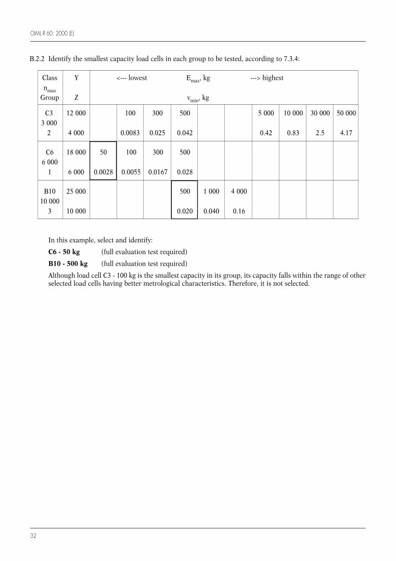
OIML R 60: 2000 (E)
32
B.2.2 Identify the smallest capacity load cells in each group to be tested, according to 7.3.4:
Class Y <--- lowest Emax, kg ---> highestnmax
Group Z vmin, kg
C3 12 000 100 300 500 5 000 10 000 30 000 50 0003 000
2 4 000 0.0083 0.025 0.042 0.42 0.83 2.5 4.17
C6 18 000 50 100 300 5006 000
1 6 000 0.0028 0.0055 0.0167 0.028
B10 25 000 500 1 000 4 00010 000
3 10 000 0.020 0.040 0.16
In this example, select and identify:
C6 - 50 kg (full evaluation test required)
B10 - 500 kg (full evaluation test required)
Although load cell C3 - 100 kg is the smallest capacity in its group, its capacity falls within the range of otherselected load cells having better metrological characteristics. Therefore, it is not selected.

OIML R 60: 2000 (E)
33
In this example, select and identify:
B10 - 4 000 kg (full evaluation test required)
Class Y <--- lowest Emax, kg ---> highestnmax
Group Z vmin, kg
C3 12 000 100 300 500 5 000 10 000 30 000 50 0003 000
2 4 000 0.0083 0.025 0.042 0.42 0.83 2.5 4.17
C6 18 000 50 100 300 5006 000
1 6 000 0.0028 0.0055 0.0167 0.028
B10 25 000 500 1 000 4 00010 000
3 10 000 0.020 0.040 0.16
B.2.3 Begin with the group with the best metrological characteristics (in this example, B10) and in accordancewith 7.3.5, select the next largest capacity between 5 and 10 times that of the nearest smaller capacity loadcell which has been selected. When no capacity meets this criterion, the selected load cell shall be that havingthe smallest capacity exceeding 10 times that of the nearest smaller capacity load cell which has beenselected. Continue this process until all load cell capacities in the group have been considered.
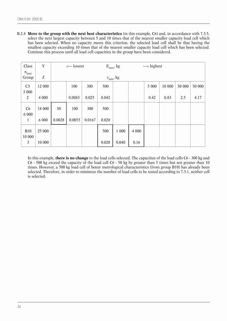
In this example, there is no change to the load cells selected. The capacities of the load cells C6 - 300 kg andC6 - 500 kg exceed the capacity of the load cell C6 - 50 kg by greater than 5 times but not greater than 10times. However, a 500 kg load cell of better metrological characteristics (from group B10) has already beenselected. Therefore, in order to minimize the number of load cells to be tested according to 7.3.1, neither cellis selected.
OIML R 60: 2000 (E)
34
B.2.4 Move to the group with the next best characteristics (in this example, C6) and, in accordance with 7.3.5,select the next largest capacity between 5 and 10 times that of the nearest smaller capacity load cell whichhas been selected. When no capacity meets this criterion, the selected load cell shall be that having thesmallest capacity exceeding 10 times that of the nearest smaller capacity load cell which has been selected.Continue this process until all load cell capacities in the group have been considered.
Class Y <--- lowest Emax, kg ---> highestnmax
Group Z vmin, kg
C3 12 000 100 300 500 5 000 10 000 30 000 50 0003 000
2 4 000 0.0083 0.025 0.042 0.42 0.83 2.5 4.17
C6 18 000 50 100 300 5006 000
1 6 000 0.0028 0.0055 0.0167 0.028
B10 25 000 500 1 000 4 00010 000
3 10 000 0.020 0.040 0.16
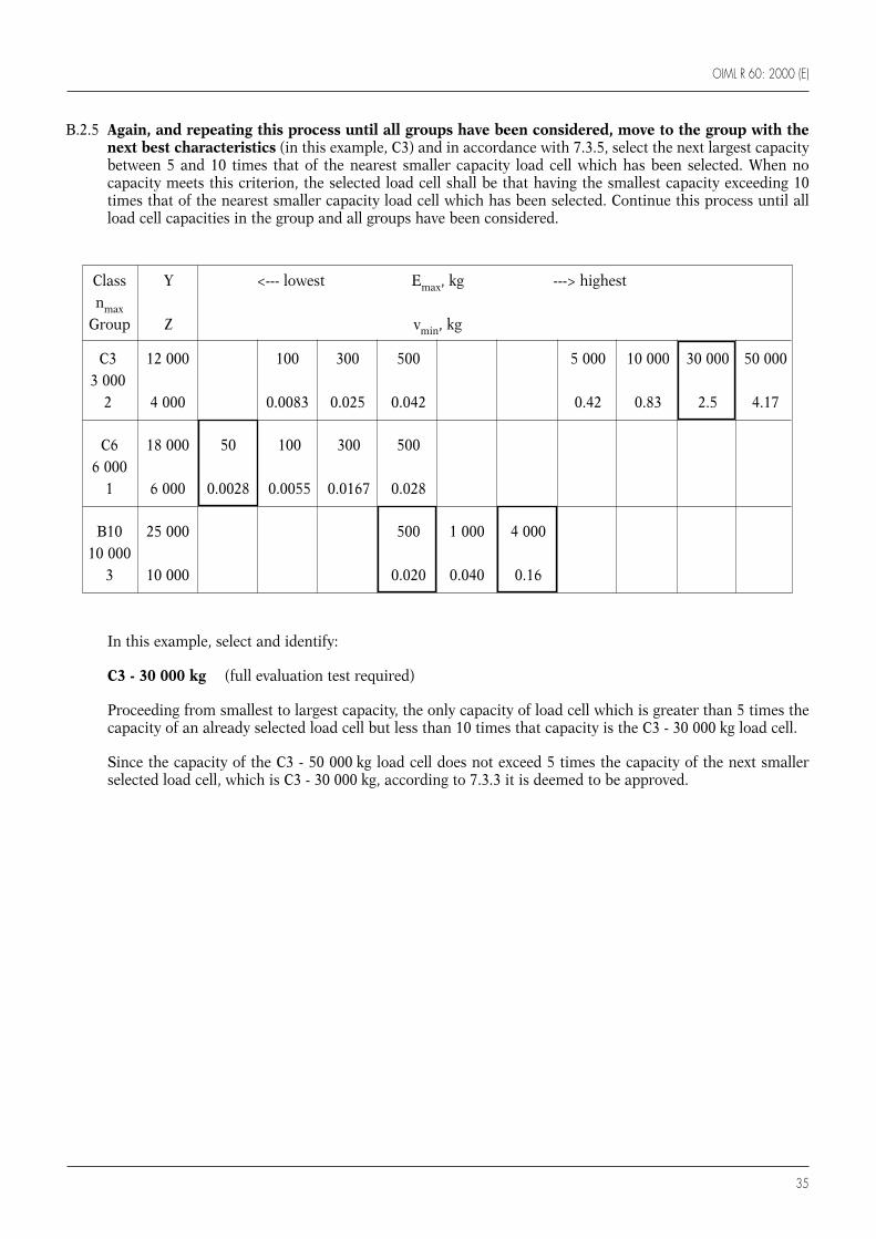
OIML R 60: 2000 (E)
35
Class Y <--- lowest Emax, kg ---> highestnmax
Group Z vmin, kg
C3 12 000 100 300 500 5 000 10 000 30 000 50 0003 000
2 4 000 0.0083 0.025 0.042 0.42 0.83 2.5 4.17
C6 18 000 50 100 300 5006 000
1 6 000 0.0028 0.0055 0.0167 0.028
B10 25 000 500 1 000 4 00010 000
3 10 000 0.020 0.040 0.16
B.2.5 Again, and repeating this process until all groups have been considered, move to the group with thenext best characteristics (in this example, C3) and in accordance with 7.3.5, select the next largest capacitybetween 5 and 10 times that of the nearest smaller capacity load cell which has been selected. When nocapacity meets this criterion, the selected load cell shall be that having the smallest capacity exceeding 10times that of the nearest smaller capacity load cell which has been selected. Continue this process until allload cell capacities in the group and all groups have been considered.
In this example, select and identify:
C3 - 30 000 kg (full evaluation test required)
Proceeding from smallest to largest capacity, the only capacity of load cell which is greater than 5 times thecapacity of an already selected load cell but less than 10 times that capacity is the C3 - 30 000 kg load cell.
Since the capacity of the C3 - 50 000 kg load cell does not exceed 5 times the capacity of the next smallerselected load cell, which is C3 - 30 000 kg, according to 7.3.3 it is deemed to be approved.

OIML R 60: 2000 (E)
36
Inspect the values of vmin, Y, and Z for all cells of the same capacity.
If any load cell of the same capacity has a lower vmin or higher Y than the identified load cell, that load cell(or load cells) is also liable for partial evaluation testing, specifically the conduct of additional temperatureeffect on minimum dead load, Emin and barometric pressure effect tests.
If any load cell of the same capacity has a higher Y than the selected load cell, that load cell (or load cells) isalso liable for partial evaluation testing, specifically the conduct of additional creep and DR tests.
In this example, the load cells identified above also have the best characteristics of lowest vmin, highestY and highest Z. This is normally the case, but not always.
Class Y <--- lowest Emax, kg ---> highestnmax
Group Z vmin, kg
C3 12 000 100 300 500 5 000 10 000 30 000 50 0003 000
2 4 000 0.0083 0.025 0.042 0.42 0.83 2.5 4.17
C6 18 000 50 100 300 5006 000
1 6 000 0.0028 0.0055 0.0167 0.028
B10 25 000 500 1 000 4 00010 000
3 10 000 0.020 0.040 0.16
B.2.6 After completing steps B.2.2 to B.2.5 and identifying the load cells, compare load cells of the same capacityfrom different groups. Identify the load cells with the highest accuracy class and highest nmax in each group(see shaded portion of table below). For those load cells of the same capacity but from different groups,identify only the one with the highest accuracy class and nmax and lowest vmin.

OIML R 60: 2000 (E)
37
C6 - 50 kgB10 - 500 kg
B10 - 4 000 kgC3 - 30 000 kg
None
B10 - 500 kg
None
Load cells requiring full evaluation test
Load cells requiring partial evaluation test
Load cell to be tested for humidity
Load cells equipped with electronics for additional tests
Summary Selected cells
B.2.7 If applicable, select the load cell for humidity testing in accordance with 7.3.6, that being the load cell withthe most severe characteristics, for example the greatest value of nmax or the lowest value of vmin.
In this example, the load cell with the greatest value of nmax or the lowest value of vmin is the same load cell,therefore select:
B10 - 500 kg (humidity test required)
Note: The other B10 load cells also possess the same qualifications and are possible choices. The 500 kg loadcell was chosen because it is the smallest of the applicable B10 capacities. Although the C6 - 50 kg loadcell has the lowest vmin of 0.0028, the B10 load cells have the highest nmax, highest accuracy class, andthe highest Y and Z.
B.2.8 If applicable, select the load cell for the additional tests to be performed on load cells equipped withelectronics in accordance with 7.3.6, that being the load cell with the most severe characteristics, for examplethe greatest value of nmax or the lowest value of vmin.
In this example, no load cell in the family is equipped with electronics.
B.2.9 Summarizing, the load cells selected for test are:

OIML R 60: 2000 (E)
38
Annex C
(Mandatory)
Test report format - General
C.1 Introduction
C.1.1 The objective of the Test Report Format is to provide a standard format for the presentation of test resultsobtained when evaluating a load cell for conformity with the test procedures described in OIML R 60.
C.1.2 In the framework of the OIML Certificate System for Measuring Instruments, applicable to load cells inconformity with R 60 (2000 edition), use of this test report format is mandatory, in French and/or inEnglish, with translation into the national languages of the countries issuing such certificates, ifappropriate.
C.1.3 Some of the tests may have to be repeated several times and reported using several identical sheets;therefore, report pages must be numbered in the space provided at the top of each page, completed by theindication of the total number of pages.
C.2 Calculation procedures
C.2.1 In order to facilitate a comparison of the reports established in English and in French, the sameabbreviations (those of the English language) are used in both versions; the meanings of these abbreviationsis given whenever appropriate.
In testing and evaluating load cells for pattern evaluation, it is recognized that the test apparatus andpractices used by the various laboratories will be different. OIML R 60 allows for these variations and stillprovides a method for testing, recording and calculating results that are readily understandable by otherknowledgeable parties reviewing the data.
In order to achieve this ease of comparability it is necessary that those persons conducting the tests use acommon system for recording data and calculating results.
Thus, it is essential that the calculation procedures below be reviewed and followed closely in thecompletion of this test report.
C.2.2 Load cell errors (EL = Error Load test)
C.2.2.1 Complete a Table D.1 (3 runs) for each test temperature, calculate the averages and record in the right handcolumn. When five runs are necessary, use Table D.1 (5 runs).
C.2.2.2 Determine the conversion factor, f, which is the number of indicated units per load cell verification interval,v, and is used to convert all “indicated units” to “v”. It is determined from the test data averages of theincreasing load tests at the initial 20 °C nominal test temperature.
OIML R 60: 2000 (E)
39
C.2.2.3 If a test load corresponding to 75 % of the measuring range for the load cell under test (i.e., 2 250 divisionsfor a 3 000 division cell, which is Dmin plus 75 % of the difference between Dmax and Dmin) is not includedin the test loads used in Table D.1, interpolate between the adjacent upper and lower values of the averagesof all three test runs and record in Table D.2 (see 5.2.2).
C.2.2.4 Calculate the difference between the average indication on the increasing load test runs at 75 % of thedifference between Dmax and Dmin and the indication at Dmin. Divide the result (to five significant figures)by the number of verification intervals (75 % n) for that load to obtain the conversion factor, f, and recordin the tables that follow.
f = [indication at 75 % of (Dmax – Dmin) – indication at Dmin] / (0.75 × n)
C.2.2.5 Enter the average test indications of the tests at the temperatures following the initial test at a nominal20 °C in Table D.2. In recording this data, indicate a “no test load” indication as “0”. This may requiresubtracting the “no load indication” from the “test load indication” so that the first entry in the column is“0”. These “0’s” have been preprinted on the form to clarify that a dead load condition is recorded as “0”.
C.2.2.6 Calculate the reference indication, Ri, by converting the net test load, in mass units, to “v” units, bymultiplying by the conversion factor, f, for each test load and recording in the 2nd column in Table D.2.
Ri = [(test load – Dmin) / ( Dmax – Dmin)] × n × f
where f = indicated units/v
C.2.2.7 In Table D.2 calculate the difference between the average test indication and the reference indication foreach test load at each test temperature and divide by f to obtain the error, EL, for each test load in termsof v.
EL = (average test indication – reference indication) / f
C.2.2.8 Compare EL with the corresponding mpe for each test load.
C.2.3 Repeatability error (ER = Error Repeatability)
C.2.3.1 Enter data in Table D.3.
C.2.3.2 Calculate the maximum difference between the test indications on Form D.1 and divide by f to obtain therepeatability error, ER, in terms of v.
ER = (maximum indication – minimum indication) / f
C.2.3.3 Compare ER with the absolute value of the corresponding mpe for each test load.
C.2.4 Temperature effects on minimum dead load output (MDLO) (CM = Change MDLO)
C.2.4.1 Enter in Table D.4 the average indication for the initial minimum test load, Dmin, for each test temperaturefrom Table D.1.
OIML R 60: 2000 (E)
40
C.2.4.2 Calculate the difference between the average test indications for each temperature in sequence and divideby f to obtain the change in terms of v.
CM = (indication at T2 – indication at T1) / f
C.2.4.3 Divide CM by (T2 – T1) and multiply the result by 5 to determine the change in v per 5 °C.
C.2.4.4 Multiply the result by the number of vmin per v in terms of mass (as stated by the manufacturer); this resultmust not exceed pLC.
pLC ≤ [(Dmax – Dmin) / n] / vmin
C.2.5 Creep and minimum dead load output return (DR)
(CC = Creep, expressed in terms of the load cell verification interval, v)
(CDR = DR, expressed in terms of the load cell verification interval, v)
C.2.5.1 From the test indications recorded in Table D.5, calculate the greatest difference between the initialindication obtained at the test load after the stabilization period and any indication obtained over the 30-minute test period and divide by f (f must be recalculated if Dmax or Dmin for this test differ from those inthe load test using the “load cell errors” procedure, C.2.2) to obtain the creep error, CC, in terms of v.
CC = (indication – initial indication) / f
C.2.5.2 CC must not exceed 0.7 times the absolute value of the mpe for the test load.
C.2.5.3 Calculate the difference between the test indications obtained at 20 minutes and 30 minutes after the initialload application and divide by f to obtain the creep error, CC (30 – 20), in terms of v.
CC (30 – 20) = (test indication at 30 minutes – test indication at 20 minutes) / f
C.2.5.4 CC (30 – 20) must not exceed 0.15 times the absolute value of the mpe for the test load.
C.2.5.5 Calculate the difference between the test indication at the minimum test load, Dmin, before and after thecreep test and divide by f to obtain the minimum dead load output return, CDR, error in terms of v.
CDR = (minimum test load indication2 – minimum test load indication1) / f
C.2.5.6 If the time intervals specified in Table 6 have been met, CDR must not exceed 0.5 v.
If the actual time is between 100 % and 150 % of the specified time, then CDR must not exceed:
0.5 (1 – (x – 1)) in units of v, where x = actual time/specified time
C.2.5.7 OIML R 76 requires calculations involving the minimum dead output return, DR, value to be carried out.Whereas CDR expresses the minimum dead load output return in terms of v, the value of DR is expressed inunits of mass (g, kg or t).

OIML R 60: 2000 (E)
41
1 This test may not be necessary depending on the design of the load cell.
2 This test is not necessary if the load cell is marked NH or SH.
C.2.5.8 Calculate the minimum dead load output return, DR, value as follows:
DR = (Emax × CDR) / nmax
C.2.5.9 The value of DR must not exceed 0.5 v, expressed in units of mass.
C.2.5.10 Regardless of the value declared by the manufacturer for the apportionment factor, pLC, the mpe for creepshall be determined from Table 5 using the apportionment factor, pLC = 0.7 (see 5.3.1.1).
C.2.6 Barometric pressure effects1 (CP = Change Barometric Pressure)
C.2.6.1 From the test indications recorded in Table D.6, calculate the difference between the indications for eachpressure and divide by f to obtain the change, CP, in terms of v.
CP = (indication at P2 – indication at P1) / f
C.2.6.2 Divide by (P2 – P1) to determine the change in v per kilopascal (kPa).
C.2.6.3 Multiply the result by [(Dmax – Dmin) / n] / vmin in terms of mass (as stated by the manufacturer) to obtainthe result in terms of vmin / kPa.
C.2.6.4 The result must not exceed 1.
C.2.7 Humidity effects2 (CH or no mark) (CHmin = Change Humidity effect min; CHmax = Change Humidityeffect max)
C.2.7.1 From the test indications recorded in Table D.7, calculate the difference between the initial indications forthe minimum test load, Dmin, before and after the damp heat test and divide by f (f must be recalculated iffor this test Dmax or Dmin differ from those in the “load cell errors” procedure, C.2.2) to obtain the change,CHmin, in terms of v.
CHmin = [(indication at Dmin)after – (indication at Dmin)before] / f
C.2.7.2 CHmin must not exceed 0.04 nmax.
C.2.7.3 Calculate the average indications at Dmin and Dmax (see 5.5.3.1 and A.4.5) for the required number of testindications, before and after the damp heat test. Subtract the average Dmin indication from the average Dmaxindication for each test and then calculate the difference between the results before and after the damp heattest. Divide the difference by f to obtain the change, CHmax, in terms of v.
CHmax = [(indication at Dmax – indication at Dmin)after – (indication at Dmax – indication at Dmin)before] / f

OIML R 60: 2000 (E)
42
C.2.7.4 CHmax must not exceed 1 v.
C.2.8 Humidity effects3 (SH)
Report load test errors at different temperatures and humidity conditions using Forms D.1, then indicatethe results in Table D.8 utilizing the procedure contained within “load cell errors” procedure, C.2.2, in amanner similar to that used for the preparation of Table D.2.
C.3 Additional tests for load cells equipped with electronics
C.3.1 Warm-up time
C.3.1.1 Enter data on Form D.11.
C.3.1.2 Span is the result of subtraction of the indication at the minimum test load, Dmin, from the indication atthe maximum test load, Dmax.
C.3.1.3 Change is the difference between the span and the initial run span.
C.3.2 Power voltage variations
C.3.2.1 Enter data on Form D.12.
C.3.2.2 Perform load tests and record results utilizing Form D.12.
C.3.2.3 Calculate reference indications in accordance with the “load cell errors” procedure, C.2.2.
C.3.2.4 Indicate results on Form D.12.
C.3.3 Short-time power reductions
C.3.3.1 Enter data on Form D.13.
C.3.3.2 Calculate the difference, which is:
(indication with disturbance, in units – indication without disturbance, in units) / conversion factor, f .
C.3.3.3 Indicate results on Form D 13.
3 This test is not necessary if the load cell is marked NH or CH or has no humidity marking.

OIML R 60: 2000 (E)
43
C.3.4 Bursts (electrical fast transients)
C.3.4.1 Enter data on Forms D.14.1 and D.14.2.
C.3.4.2 Calculate the difference, which is:
(indication with disturbance, in units – indication without disturbance, in units) / conversion factor, f.
C.3.4.3 Indicate results on Forms D.14.1 and D.14.2.
C.3.5 Electrostatic discharge
C.3.5.1 Enter data on Forms D.15.1 and D.15.2.
C.3.5.2 Calculate the difference, which is:
(indication with disturbance, in units – indication without disturbance, in units) / conversion factor, f.
C.3.5.3 Indicate results on Forms D.15.1 and D.15.2.
C.3.5.4 Provide test point information on Form D.15.3.
C.3.6 Electromagnetic susceptibility
C.3.6.1 Enter data on Form D.16.1.
C.3.6.2 Calculate the difference, which is:
(indication with disturbance, in units – indication without disturbance, in units) / conversion factor, f.
C.3.6.3 Indicate results on Form D.16.1.
C.3.6.4 Provide test set-up information on Form D.16.2.
C.3.7 Span stability
C.3.7.1 Enter data on Forms D.17.1.1 (3 runs) to D.17.1.1 (5 runs).
C.3.7.2 Calculate averages and record on Forms D.17.1.1 (3 runs) to 17.1.1 (5 runs).
C.3.7.3 Indicate results on Form D.17.2.

OIML R 60: 2000 (E)
44
C.4 General notes
C.4.1 Absolute (not relative) time shall be recorded.
C.4.2 The calculations made do not include the application of 5.2.1. To ensure that these requirements are met,the calculations should be carried out using lower n values than the nmax specified.
C.4.3 It should be sufficient to carry out the calculations with:
n = nmax – 500 and n = nmax – 1 000 (provided 500 < n).
C.4.4 Check to make certain that: vmin < v
vmin < (Dmax – Dmin) / nmax
C.4.5 Check calculations not only at nmax but at (applying 5.2.1):
nmax – 500
nmax – 1 000
C.4.6 Indicate the result in the “Summary of test” portion of the test report.
C.4.7 The testing laboratory may submit any graphs or plots depicting the test results on the following pages ofthis report.
Note: For example, Figure C.1 gives a sample plot depicting the combined errors versus applied load.
C.4.8 When reporting values for individual test data, the data should be truncated to two significant digits to theright of the decimal place and reported in load cell verification intervals, v.
Figure C.1 Example of an error envelope
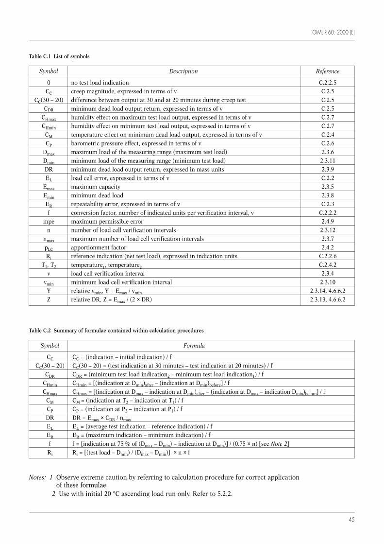
OIML R 60: 2000 (E)
45
Symbol Description Reference
0 no test load indication C.2.2.5CC creep magnitude, expressed in terms of v C.2.5
CC(30 – 20) difference between output at 30 and at 20 minutes during creep test C.2.5CDR minimum dead load output return, expressed in terms of v C.2.5
CHmax humidity effect on maximum test load output, expressed in terms of v C.2.7CHmin humidity effect on minimum test load output, expressed in terms of v C.2.7
CM temperature effect on minimum dead load output, expressed in terms of v C.2.4CP barometric pressure effect, expressed in terms of v C.2.6
Dmax maximum load of the measuring range (maximum test load) 2.3.6Dmin minimum load of the measuring range (minimum test load) 2.3.11DR minimum dead load output return, expressed in mass units 2.3.9EL load cell error, expressed in terms of v C.2.2
Emax maximum capacity 2.3.5Emin minimum dead load 2.3.8ER repeatability error, expressed in terms of v C.2.3f conversion factor, number of indicated units per verification interval, v C.2.2.2
mpe maximum permissible error 2.4.9n number of load cell verification intervals 2.3.12
nmax maximum number of load cell verification intervals 2.3.7pLC apportionment factor 2.4.2Ri reference indication (net test load), expressed in indication units C.2.2.6
T1, T2 temperature1, temperature2 C.2.4.2v load cell verification interval 2.3.4
vmin minimum load cell verification interval 2.3.10Y relative vmin, Y = Emax / vmin 2.3.14, 4.6.6.2Z relative DR, Z = Emax / (2 × DR) 2.3.13, 4.6.6.2
Notes: 1 Observe extreme caution by referring to calculation procedure for correct applicationof these formulae.
2 Use with initial 20 °C ascending load run only. Refer to 5.2.2.
Symbol Formula
CC CC = (indication – initial indication) / fCC(30 – 20) CC(30 – 20) = (test indication at 30 minutes – test indication at 20 minutes) / f
CDR CDR = (minimum test load indication2 – minimum test load indication1) / fCHmin CHmin = [(indication at Dmin)after – (indication at Dmin)before] / fCHmax CHmax = [(indication at Dmax – indication at Dmin)after – (indication at Dmax – indication Dmin)before] / f
CM CM = (indication at T2 – indication at T1) / fCP CP = (indication at P2 – indication at P1) / fDR DR = Emax × CDR / nmax
EL EL = (average test indication – reference indication) / fER ER = (maximum indication – minimum indication) / ff f = [indication at 75 % of (Dmax – Dmin) – indication at Dmin)] / (0.75 × n) [see Note 2]
Ri Ri = [(test load – Dmin) / (Dmax – Dmin)] × n × f
Table C.2 Summary of formulae contained within calculation procedures
Table C.1 List of symbols

OIML R 60: 2000 (E)
46
Annex D
(Mandatory)
Test report format - Forms
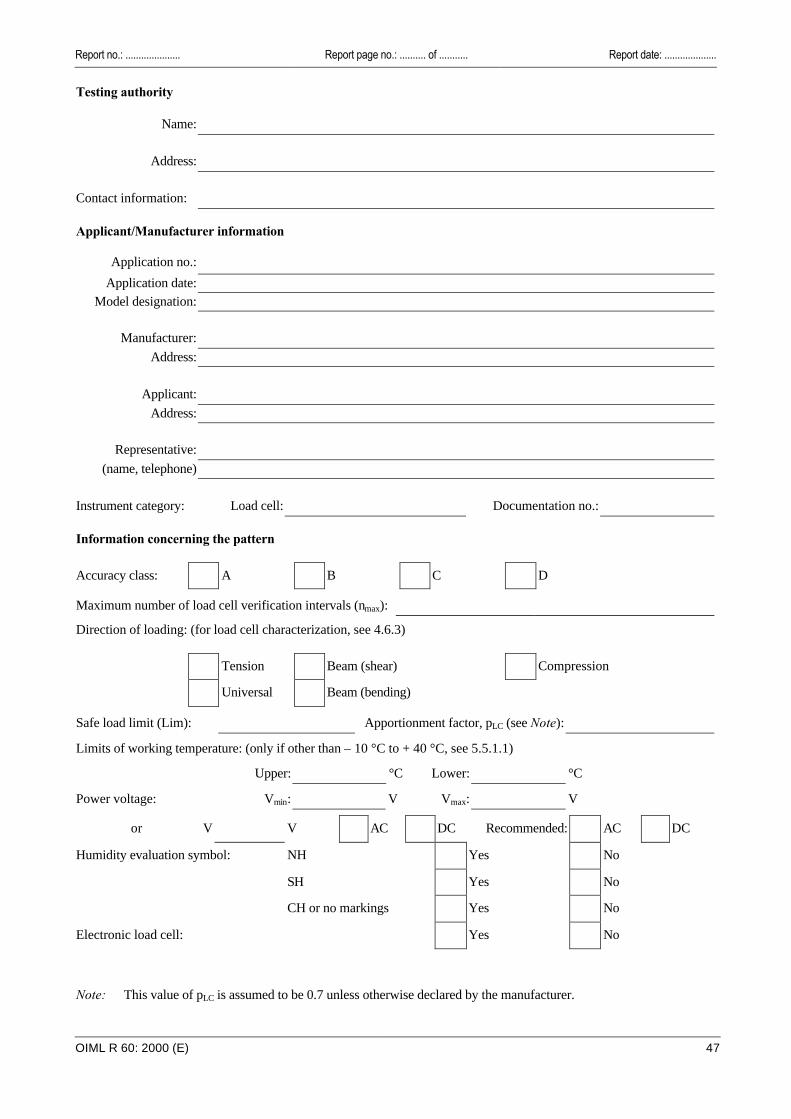
Report no.: ..................... Report page no.: .......... of ........... Report date: ....................
OIML R 60: 2000 (E) 47
Testing authority
Name:
Address:
Contact information: Applicant/Manufacturer information
Application no.:
Application date:
Model designation:
Manufacturer:
Address:
Applicant:
Address:
Representative:
(name, telephone)
Instrument category: Load cell: Documentation no.: Information concerning the pattern
Accuracy class: A B C D
Maximum number of load cell verification intervals (nmax): Direction of loading: (for load cell characterization, see 4.6.3)
Tension Beam (shear) Compression
Universal Beam (bending)
Safe load limit (Lim): Apportionment factor, pLC (see Note):
Limits of working temperature: (only if other than – 10 °C to + 40 °C, see 5.5.1.1)
Upper: °C Lower: °C
Power voltage: Vmin: V Vmax: V
or V V AC DC Recommended: AC DC
Humidity evaluation symbol: NH Yes No
SH Yes No
CH or no markings Yes No
Electronic load cell: Yes No
Note: This value of pLC is assumed to be 0.7 unless otherwise declared by the manufacturer.
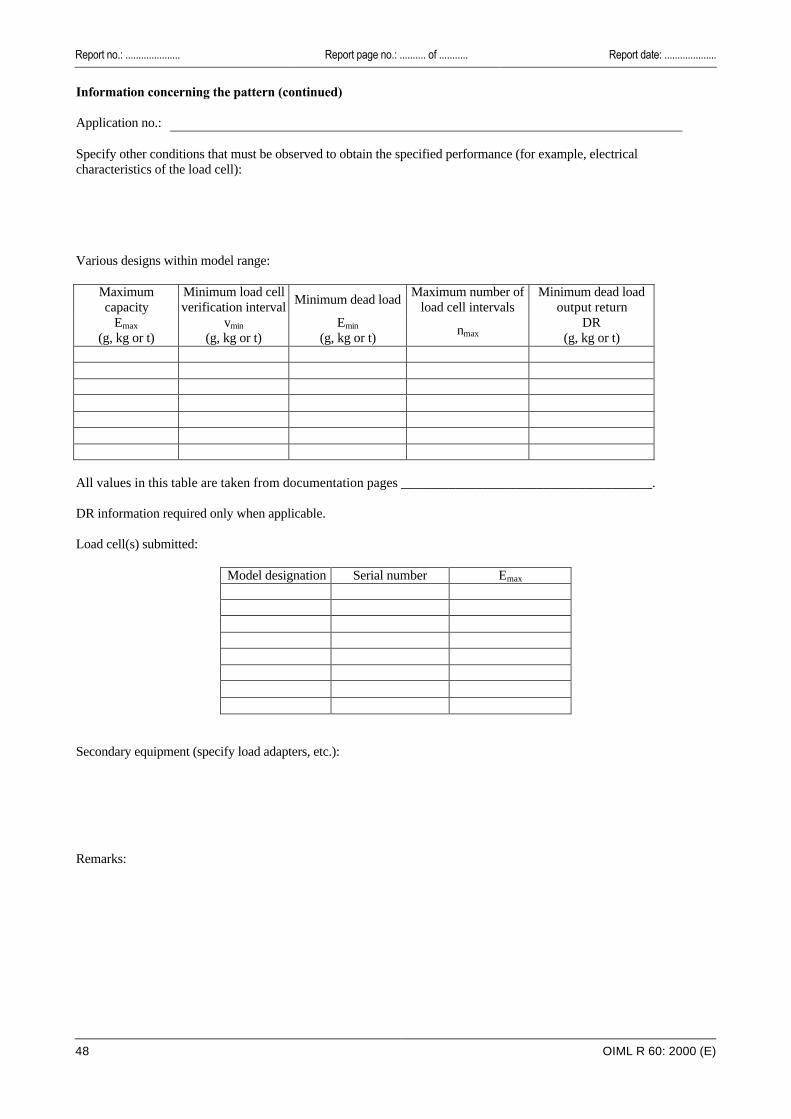
Report no.: ..................... Report page no.: .......... of ........... Report date: ....................
48 OIML R 60: 2000 (E)
Information concerning the pattern (continued) Application no.: Specify other conditions that must be observed to obtain the specified performance (for example, electrical characteristics of the load cell): Various designs within model range:
Maximum capacity
Minimum load cell verification interval
Minimum dead load Maximum number of
load cell intervals Minimum dead load
output return Emax
(g, kg or t)
vmin
(g, kg or t)
Emin
(g, kg or t) nmax
DR (g, kg or t)
All values in this table are taken from documentation pages _____________________________________. DR information required only when applicable. Load cell(s) submitted:
Model designation Serial number Emax
Secondary equipment (specify load adapters, etc.): Remarks:

Report no.: ..................... Report page no.: .......... of ........... Report date: ....................
OIML R 60: 2000 (E) 49
General information concerning test conditions Ref.: A.3 Application no.: Load cell model: Serial no.: Emax:
nmax: vmin: DR (if applicable): Force-generating system - description:
(see Note) Minimum test load Indicating instrument - description: Environmental equipment - description:
Temperature: °C
Relative humidity: % Barometric pressure: kPa
Test location: Acceleration of gravity at test location: m/sec2
Evaluator:
Note: Include information concerning accuracy (for example, accredited laboratory).

Report no.: ..................... Report page no.: .......... of ........... Report date: ....................
50 OIML R 60: 2000 (E)
Summary of the test
Application no.:
Load cell model:
Serial no.:
Emax: nmax:
vmin: DR:
Force-generating system: pLC:
Indicating instrument:
Evaluator:
No. Test description Passed Failed Report page
Remarks
D.2 Load cell errors (EL)
D.3 Repeatability errors (ER)
D.4 Temperature effects on MDLO (CM)
D.5 Creep (CC)
D.5 DR (CDR) (see Note 2) DR =
D.6 Barometric pressure effects (CP)
D.7 Humidity effects (CH or no mark) (CHmin)
D.7 Humidity effects (CH or no mark) (CHmax)
D.8 Humidity effects (SH)
D.9 Marking requirements
D.10 Load cells equipped with electronics
D.11 Warm-up time
D.12 Power voltage variations
D.13 Short time power reductions
D.14 Bursts (electrical fast transients)
D.15 Electrostatic discharge
D.16 Electromagnetic susceptibility
D.17 Span stability
The following table checks the required calculations as per the General notes provisions of C.3:
nmax (g, kg or t)
nmax – 500 (g, kg or t)
nmax – 1 000 (g, kg or t) No. Test description
+ – + – + –
D.2 Check that max
minmaxmin
n
DDv
−≤
Worst case figure for minimum dead load output return error (in mass units) = DR = see Note 3
Notes: 1 Enter "NA" for "the test is not applicable". 2 Record error to accommodate OIML R 76. 3 This DR value is used in association with OIML R 76.

Report no.: ..................... Report page no.: .......... of ........... Report date: ....................
OIML R 60: 2000 (E) 51
Form D.1 (3 runs) Load test data (EL) Ref.: A.4.1.1 to A.4.1.11. Complete one sheet for each test temperature, one for each humidity (SH) test in A.4.6, and
when applicable, one for each electronics power voltage in A.4.7.3.
Application no.: At start At end
Load cell model: Date:
Serial no.: Temperature: °C
Emax: Relative humidity: %
nmax: Barometric pressure: kPa
vmin: Indicator temperature: °C
pLC: DR:
Force-generating system:
Indicating instrument:
Electronics power voltage (when applicable): V
Evaluator:
Table D.1 (3 runs)
Run no. 1 Run no. 2 Run no. 3 Test load (g, kg or t) Indication
( ) Time
Indication ( )
Time Indication ( )
Time
Average indication ( )
Repeatability error
( )
0
0
0
0
0 *
Notes: 1 * = Average initial minimum test load indication. 2 Absolute (not relative) time shall be recorded.
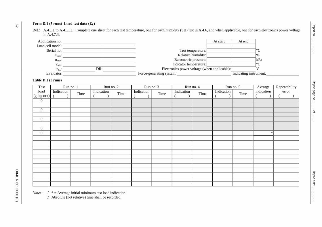
52
Report no.: .....................
Report page no.: .......... of ...........
OIM
L R
60
: 20
00
(E)
Form D.1 (5 runs) Load test data (EL)
Ref.: A.4.1.1 to A.4.1.11. Complete one sheet for each test temperature, one for each humidity (SH) test in A.4.6, and when applicable, one for each electronics power voltage in A.4.7.3.
Application no.: At start At end Load cell model:
Serial no.: Test temperature: °C Emax: Relative humidity: % nmax: Barometric pressure: kPa vmin: Indicator temperature: °C pLC: DR: Electronics power voltage (when applicable): V
Evaluator: Force-generating system: Indicating instrument:
Table D.1 (5 runs)
Run no. 1 Run no. 2 Run no. 3 Run no. 4 Run no. 5 Test load
(g, kg or t) Indication ( )
Time Indication ( )
Time Indication ( )
Time Indication ( )
Time Indication ( )
Time
Average indication ( )
Repeatability error
( ) 0 0 0 0 0 *
Notes: 1 * = Average initial minimum test load indication. 2 Absolute (not relative) time shall be recorded.
Report date: ....................

Report no.: ..................... Report page no.: .......... of ........... Report date: ....................
OIML R 60: 2000 (E) 53
Form D.2 Load cell errors (EL) calculation Ref.: 5.1.1; A.4.1.12 to A.4.1.14; C.2.2.
Application no.: At start At end
Load cell model: Date:
Serial no.: Temperature: °C
Emax: Relative humidity: %
nmax: Barometric pressure: kPa
vmin: Indicator temperature: °C
pLC: DR:
Force-generating system: Conversion factor, f:
Indicating instrument: 75 % test load (g, kg or t):
Evaluator: Reference indication at 75 % test load:
Table D.2
. . . . °C (20 °C) . . . . °C (40 °C) . . . . °C (– 10 °C) . . . . °C (20 °C) Test load
(g, kg or t)
Reference indication ( )
Indication ( )
Error (EL) (v)
Indication ( )
Error (EL) (v)
Indication ( )
Error (EL) (v)
Indication ( )
Error (EL) (v)
mpe
(v)
0 0 0 0 0 0
Minimum test load, Dmin: PASS: FAIL:
Notes: 1 Load/reference indications: if a 75 % load point was not obtained, a straight line interpolation between the adjacent higher and lower load point indications is used (see 5.2.2 and calculation procedures in C.2.2).
2 Error, EL: the difference between the test indication and the reference indication divided by the conversion factor, f.
3 Test load values are values above minimum test load, Dmin.
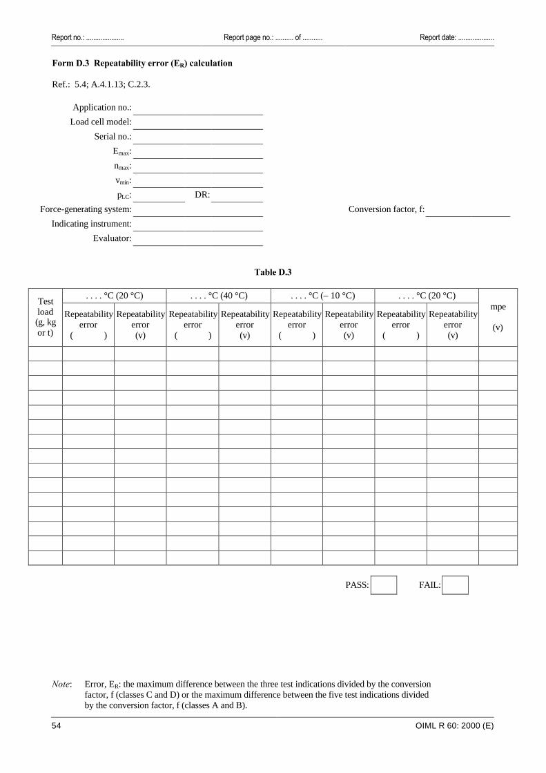
Report no.: ..................... Report page no.: .......... of ........... Report date: ....................
54 OIML R 60: 2000 (E)
Form D.3 Repeatability error (ER) calculation Ref.: 5.4; A.4.1.13; C.2.3.
Application no.:
Load cell model:
Serial no.:
Emax:
nmax:
vmin:
pLC: DR:
Force-generating system: Conversion factor, f:
Indicating instrument:
Evaluator:
Table D.3
. . . . °C (20 °C) . . . . °C (40 °C) . . . . °C (– 10 °C) . . . . °C (20 °C) Test load (g, kg or t)
Repeatability error
( )
Repeatability error (v)
Repeatability error
( )
Repeatability error (v)
Repeatability error
( )
Repeatability error (v)
Repeatability error
( )
Repeatability error (v)
mpe
(v)
PASS: FAIL:
Note: Error, ER: the maximum difference between the three test indications divided by the conversion factor, f (classes C and D) or the maximum difference between the five test indications divided by the conversion factor, f (classes A and B).
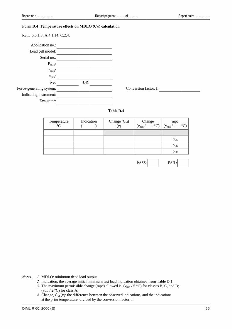
Report no.: ..................... Report page no.: .......... of ........... Report date: ....................
OIML R 60: 2000 (E) 55
Form D.4 Temperature effects on MDLO (CM) calculation Ref.: 5.5.1.3; A.4.1.14; C.2.4.
Application no.:
Load cell model:
Serial no.:
Emax:
nmax:
vmin:
pLC: DR:
Force-generating system: Conversion factor, f:
Indicating instrument:
Evaluator:
Table D.4
Temperature °C
Indication ( )
Change (CM) (v)
Change (vmin / . . . . °C)
mpc (vmin / . . . . °C)
pLC
pLC
pLC
PASS: FAIL:
Notes: 1 MDLO: minimum dead load output. 2 Indication: the average initial minimum test load indication obtained from Table D.1. 3 The maximum permissible change (mpc) allowed is: (vmin / 5 °C) for classes B, C, and D;
(vmin / 2 °C) for class A. 4 Change, CM (v): the difference between the observed indications, and the indications
at the prior temperature, divided by the conversion factor, f.

Report no.: ..................... Report page no.: .......... of ........... Report date: ....................
56 OIML R 60: 2000 (E)
Form D.5 Creep (CC) and DR (CDR)
Ref.: 5.3.1, 5.3.2; A.4.2, A.4.3. Complete one sheet for each test temperature.
Application no.: At start At end
Load cell model: Date:
Serial no.: Temperature: °C
Emax: Relative humidity: %
nmax: Barometric pressure: kPa
vmin: Indicator temperature: °C
pLC: DR:
Force-generating system: Conversion factor, f:
Indicating instrument:
Evaluator:
Table D.5
Test load (g, kg or t)
Indication ( )
Barometric pressure
Time Change
(v) mpc (v)
0
0
0
Exercise cells
These rows may be omitted for a load sequence as
shown in Figure A.2 0
(*) →→ 0 ← initial “no load” indication Fill in time →→ Record time of initial loading →
(**) →→ ← initial “load” indication
Constant maximum test load,
Dmax
Fill in time →→ Record time of initial unloading →
(***) →→ 0 ← initial indication 0 0 0 0
These rows are for
reference purposes only
0 30 – 20 minute creep difference in units:
DR (v): 30 minute creep: PASS: FAIL: actual time (s): 30 – 20 minute creep difference: PASS: FAIL:
specified time (s): DR < 0.5 v: PASS: FAIL: mpc for DR (v): MDLOR within DR requirements: PASS: FAIL:
Notes: 1 Change (v) for creep: the observed indication minus the initial "load" indication (**) divided by the conversion factor, f.
2 Determine the difference between the reading obtained at 20 minutes and the reading obtained at 30 minutes (see 5.3.1).
3 Change (v) for DR: the initial indication (***) minus the initial "no load" indication (*) divided by the conversion factor, f.
4 Absolute (not relative) time shall be recorded.

Report no.: ..................... Report page no.: .......... of ........... Report date: ....................
OIML R 60: 2000 (E) 57
Form D.6 Barometric pressure effects (CP) Ref.: 5.5.2; A.4.4.
Application no.: At start At end
Load cell model: Date:
Serial no.: Temperature: °C
Emax: Relative humidity: %
nmax: Barometric pressure: kPa
vmin: Indicator temperature: °C
pLC: DR:
Force-generating system: Conversion factor, f:
Indicating instrument:
Evaluator:
Table D.6
Pressure (kPa)
Indication ( )
Time Change
(v) Change
(vmin / kPa) mpc
(vmin / kPa)
0 0 0
1
1
1
1
PASS: FAIL:
Remarks:
Notes: 1 Change (vmin / kPa): the difference between the observed indication and the initial indication divided by the conversion factor, f.
2 Although A.4.4 specifies a change of only 1 kPa for this test, additional measurements may be taken.
3 Absolute (not relative) time shall be recorded.
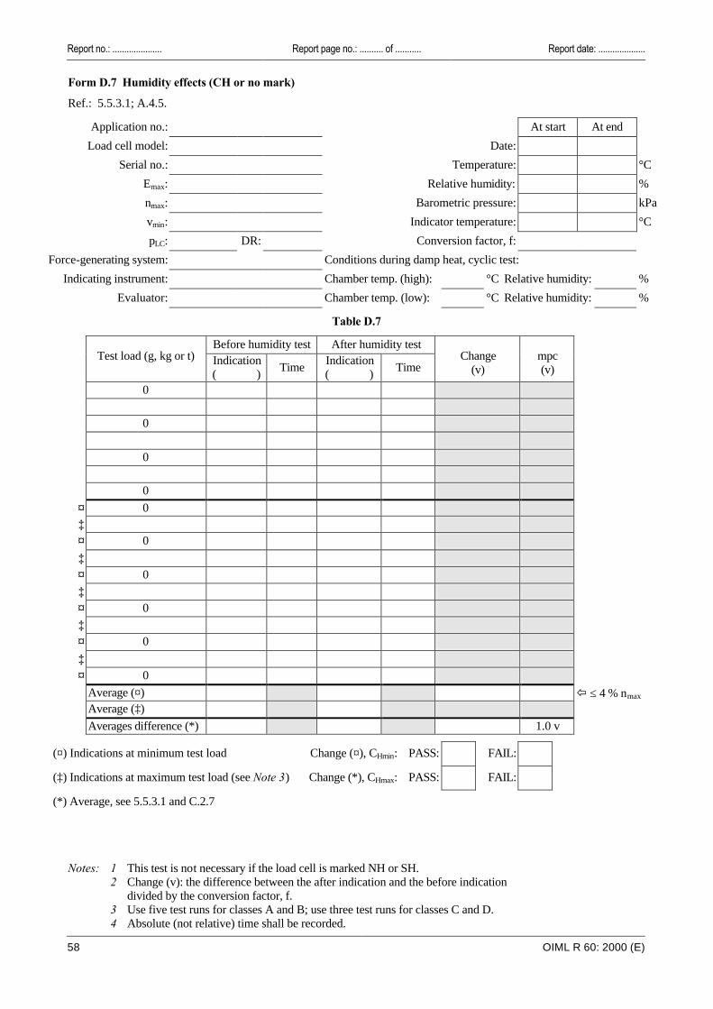
Report no.: ..................... Report page no.: .......... of ........... Report date: ....................
58 OIML R 60: 2000 (E)
Form D.7 Humidity effects (CH or no mark)
Ref.: 5.5.3.1; A.4.5.
Application no.: At start At end
Load cell model: Date:
Serial no.: Temperature: °C
Emax: Relative humidity: %
nmax: Barometric pressure: kPa
vmin: Indicator temperature: °C
pLC: DR: Conversion factor, f:
Force-generating system: Conditions during damp heat, cyclic test:
Indicating instrument: Chamber temp. (high): °C Relative humidity: %
Evaluator: Chamber temp. (low): °C Relative humidity: %
Table D.7
Before humidity test After humidity test
Test load (g, kg or t) Indication
( ) Time
Indication ( )
Time Change
(v) mpc (v)
0
0
0
0
¤ 0 ‡
¤ 0
‡
¤ 0
‡
¤ 0
‡
¤ 0
‡
¤ 0
Average (¤) ï ≤ 4 % nmax Average (‡)
Averages difference (*) 1.0 v
(¤) Indications at minimum test load Change (¤), CHmin: PASS: FAIL:
(‡) Indications at maximum test load (see Note 3) Change (*), CHmax: PASS: FAIL:
(*) Average, see 5.5.3.1 and C.2.7
Notes: 1 This test is not necessary if the load cell is marked NH or SH. 2 Change (v): the difference between the after indication and the before indication
divided by the conversion factor, f. 3 Use five test runs for classes A and B; use three test runs for classes C and D. 4 Absolute (not relative) time shall be recorded.
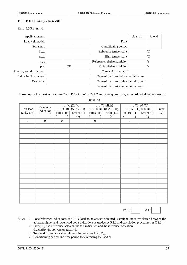
Report no.: ..................... Report page no.: .......... of ........... Report date: ....................
OIML R 60: 2000 (E) 59
Form D.8 Humidity effects (SH) Ref.: 5.5.3.2; A.4.6.
Application no.: At start At end
Load cell model: Date:
Serial no.: Conditioning period:
Emax: Reference temperature: °C
nmax: High temperature: °C
vmin: Reference relative humidity: %
pLC: DR: High relative humidity: %
Force-generating system: Conversion factor, f:
Indicating instrument: Page of load test before humidity test:
Evaluator: Page of load test during humidity test:
Page of load test after humidity test:
Summary of load test errors: use Form D.1 (3 runs) or D.1 (5 runs), as appropriate, to record individual test results.
Table D.8
. . . . °C (20 °C) . . . . % RH (50 % RH)
. . . . °C (High) . . . . % RH (85 % RH)
. . . . °C (20 °C) . . . . % RH (50 % RH) Test load
(g, kg or t)
Reference indication ( ) Indication
( ) Error (EL)
(v) Indication ( )
Error (EL) (v)
Indication ( )
Error (EL) (v)
mpe (v)
0 0 0 0 0
PASS: FAIL:
Notes: 1 Load/reference indications: if a 75 % load point was not obtained, a straight line interpolation between the adjacent higher and lower load point indications is used, (see 5.2.2 and calculation procedures in C.2.2).
2 Error, EL: the difference between the test indication and the reference indication divided by the conversion factor, f.
3 Test load values are values above minimum test load, Dmin. 4 Conditioning period: the time period for exercising the load cell.
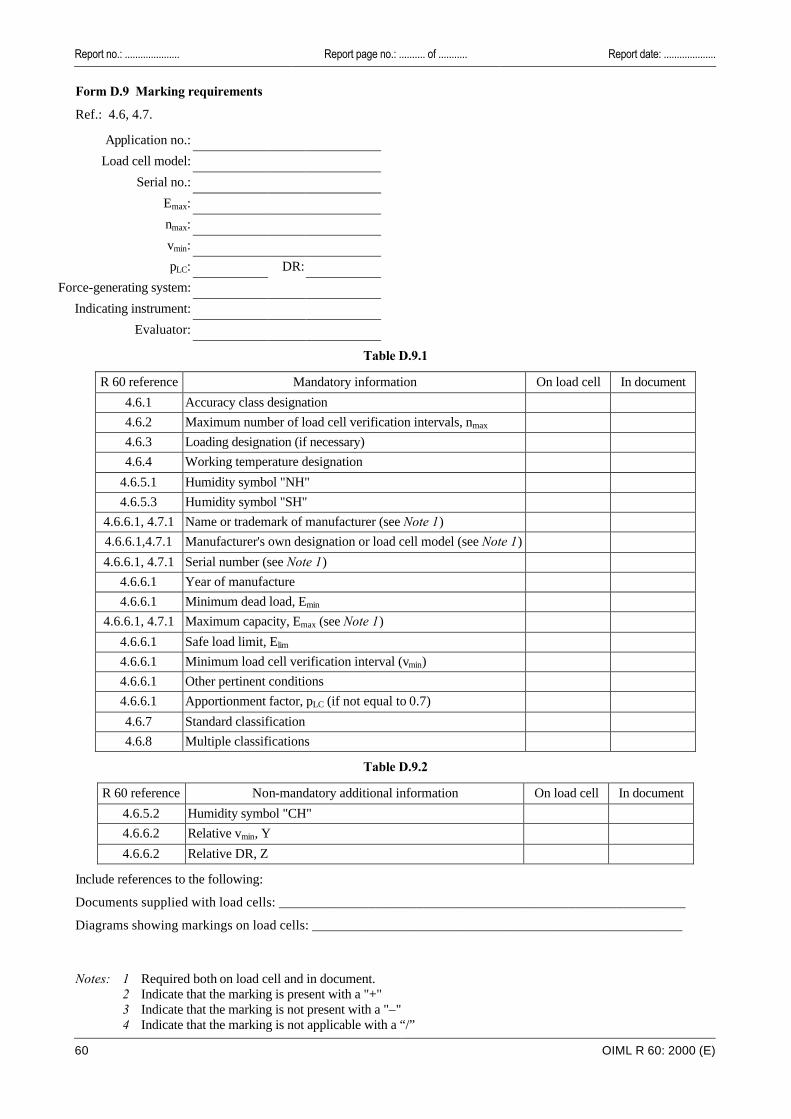
Report no.: ..................... Report page no.: .......... of ........... Report date: ....................
60 OIML R 60: 2000 (E)
Form D.9 Marking requirements
Ref.: 4.6, 4.7.
Application no.:
Load cell model:
Serial no.:
Emax:
nmax:
vmin:
pLC: DR:
Force-generating system:
Indicating instrument:
Evaluator:
Table D.9.1
R 60 reference Mandatory information On load cell In document
4.6.1 Accuracy class designation
4.6.2 Maximum number of load cell verification intervals, nmax
4.6.3 Loading designation (if necessary)
4.6.4 Working temperature designation
4.6.5.1 Humidity symbol "NH"
4.6.5.3 Humidity symbol "SH"
4.6.6.1, 4.7.1 Name or trademark of manufacturer (see Note 1)
4.6.6.1,4.7.1 Manufacturer's own designation or load cell model (see Note 1)
4.6.6.1, 4.7.1 Serial number (see Note 1)
4.6.6.1 Year of manufacture
4.6.6.1 Minimum dead load, Emin
4.6.6.1, 4.7.1 Maximum capacity, Emax (see Note 1)
4.6.6.1 Safe load limit, Elim
4.6.6.1 Minimum load cell verification interval (vmin)
4.6.6.1 Other pertinent conditions
4.6.6.1 Apportionment factor, pLC (if not equal to 0.7)
4.6.7 Standard classification
4.6.8 Multiple classifications
Table D.9.2
R 60 reference Non-mandatory additional information On load cell In document
4.6.5.2 Humidity symbol "CH"
4.6.6.2 Relative vmin, Y
4.6.6.2 Relative DR, Z
Include references to the following:
Documents supplied with load cells: ___________________________________________________________
Diagrams showing markings on load cells: ______________________________________________________
Notes: 1 Required both on load cell and in document. 2 Indicate that the marking is present with a "+" 3 Indicate that the marking is not present with a "–" 4 Indicate that the marking is not applicable with a “/”
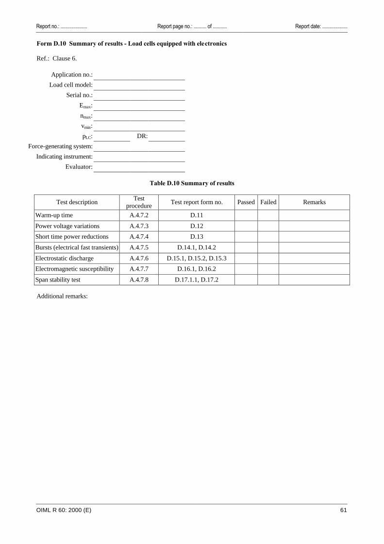
Report no.: ..................... Report page no.: .......... of ........... Report date: ....................
OIML R 60: 2000 (E) 61
Form D.10 Summary of results - Load cells equipped with electronics Ref.: Clause 6.
Application no.:
Load cell model:
Serial no.:
Emax:
nmax:
vmin:
pLC: DR:
Force-generating system:
Indicating instrument:
Evaluator:
Table D.10 Summary of results
Test description Test
procedure Test report form no. Passed Failed Remarks
Warm-up time A.4.7.2 D.11
Power voltage variations A.4.7.3 D.12
Short time power reductions A.4.7.4 D.13
Bursts (electrical fast transients) A.4.7.5 D.14.1, D.14.2
Electrostatic discharge A.4.7.6 D.15.1, D.15.2, D.15.3
Electromagnetic susceptibility A.4.7.7 D.16.1, D.16.2
Span stability test A.4.7.8 D.17.1.1, D.17.2
Additional remarks:

62
Report no.: .....................
Report page no.: .......... of ...........
OIM
L R
60
: 20
00
(E)
Form D.11 Warm-up time
Ref.: 6.3.2; A.4.7.2.
Application no.: At start At end
Load cell model: Date:
Serial no.: Time:
Emax: Temperature: °C
nmax: Relative humidity: %
vmin: Barometric pressure: kPa
pLC: DR: Conversion factor, f:
Force-generating system: Minimum test load, Dmin:
Indicating instrument: Maximum test load, Dmax:
Evaluator: Duration of disconnection before test:
Table D.11
Initial run After 5 min. After 15 min. After 30 min.
Indication ( )
Time Indication ( )
Time Indication ( )
Time Indication ( )
Time
mpc
(v)
Minimum test load
Maximum test load
Span ( )
Span (v)
Change (v) 0
PASS: FAIL:
Notes: 1 Absolute (not relative) time shall be recorded. 2 Span: the result of subtracting the indication at minimum test load from the indication at maximum test
load. All span errors (error at maximum test load minus the error at minimum test load) shall be within the maximum permissible error during the 30 minute test.
3 Change: the difference between the span and the initial run span. 4 Maximum permissible change, mpc: the absolute value of the maximum permissible error for the
maximum test load applied.
Report date: ....................
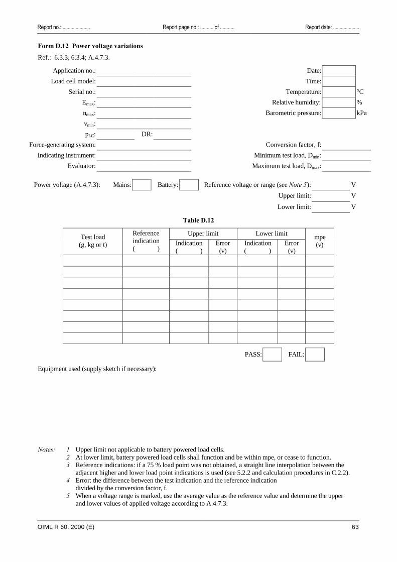
Report no.: ..................... Report page no.: .......... of ........... Report date: ....................
OIML R 60: 2000 (E) 63
Form D.12 Power voltage variations
Ref.: 6.3.3, 6.3.4; A.4.7.3.
Application no.: Date:
Load cell model: Time:
Serial no.: Temperature: °C
Emax: Relative humidity: %
nmax: Barometric pressure: kPa
vmin:
pLC: DR:
Force-generating system: Conversion factor, f:
Indicating instrument: Minimum test load, Dmin:
Evaluator: Maximum test load, Dmax:
Power voltage (A.4.7.3): Mains: Battery: Reference voltage or range (see Note 5): V
Upper limit: V
Lower limit: V
Table D.12
Upper limit Lower limit Test load (g, kg or t)
Reference indication ( )
Indication ( )
Error (v)
Indication ( )
Error (v)
mpe (v)
PASS: FAIL:
Equipment used (supply sketch if necessary):
Notes: 1 Upper limit not applicable to battery powered load cells. 2 At lower limit, battery powered load cells shall function and be within mpe, or cease to function. 3 Reference indications: if a 75 % load point was not obtained, a straight line interpolation between the
adjacent higher and lower load point indications is used (see 5.2.2 and calculation procedures in C.2.2). 4 Error: the difference between the test indication and the reference indication
divided by the conversion factor, f. 5 When a voltage range is marked, use the average value as the reference value and determine the upper
and lower values of applied voltage according to A.4.7.3.

64
Report no.: .....................
Report page no.: .......... of ...........
OIM
L R
60
: 20
00
(E)
Form D.13 Short time power reductions
Ref.: 6.3.5; A.4.7.4.
Application no.: Date:
Load cell model: Time:
Serial no.: Temperature: °C
Emax: Relative humidity: %
nmax: Barometric pressure: kPa
vmin:
pLC: DR: Conversion factor, f:
Force-generating system: Minimum test load, Dmin:
Indicating instrument: Reference voltage range: V
Evaluator:
Table D.13
Disturbance Result
Significant fault > vmin Test load
(g, kg or t) Amplitude (%)
Duration (cycles)
Number of disturbances
Repetition interval (s)
Indication ( )
Difference (v) No Yes (remarks)
without disturbance
0 0.5 10
50 1 10
PASS: FAIL: Equipment used (supply sketch if necessary): Remarks:
Note: In the case of a voltage range, use the average value as the reference value.
Report date: ....................

Report no.: ..................... Report page no.: .......... of ........... Report date: ....................
OIML R 60: 2000 (E) 65
Form D.14.1 Bursts (electrical fast transients) - power supply lines Ref.: 6.3.5; A.4.7.5.
Application no.: Date:
Load cell model: Time:
Serial no.: Temperature: °C
Emax: Relative humidity: %
nmax: Barometric pressure: kPa
vmin:
pLC: DR:
Force-generating system: Conversion factor, f:
Indicating instrument: Minimum test load, Dmin:
Evaluator:
Table D.14.1
Power supply lines: test voltage = 1 kV; duration of the test = 1 minute at each polarity.
Connection Result
Significant fault > vmin Test load
(g, kg or t) L to
ground
N to
ground
PE to
ground
Polarity Indication ( )
Difference (v) No Yes (remarks)
without disturbance
X pos
neg
without disturbance
X pos
neg
without disturbance
X pos
neg
PASS: FAIL:
L = phase, N = neutral, PE = protective earth Equipment used (supply sketch if necessary): Remarks:
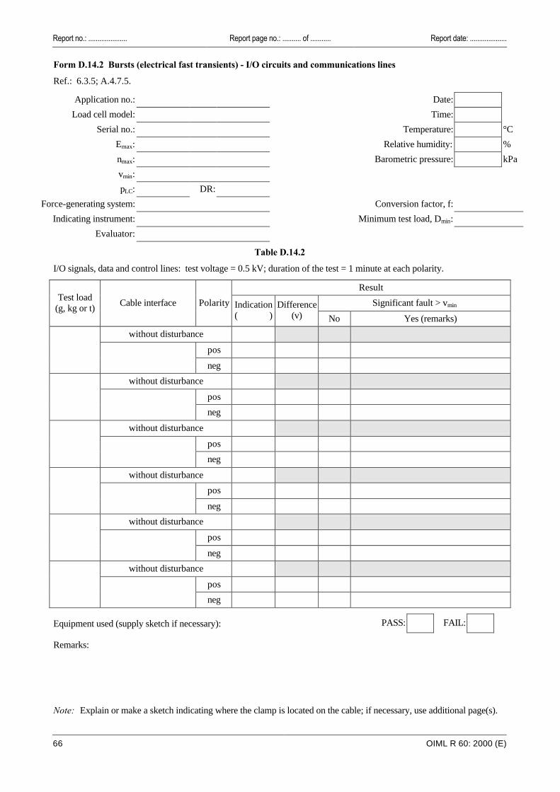
Report no.: ..................... Report page no.: .......... of ........... Report date: ....................
66 OIML R 60: 2000 (E)
Form D.14.2 Bursts (electrical fast transients) - I/O circuits and communications lines
Ref.: 6.3.5; A.4.7.5.
Application no.: Date:
Load cell model: Time:
Serial no.: Temperature: °C
Emax: Relative humidity: %
nmax: Barometric pressure: kPa
vmin:
pLC: DR:
Force-generating system: Conversion factor, f:
Indicating instrument: Minimum test load, Dmin:
Evaluator:
Table D.14.2
I/O signals, data and control lines: test voltage = 0.5 kV; duration of the test = 1 minute at each polarity.
Result
Significant fault > vmin Test load
(g, kg or t) Cable interface Polarity Indication
( ) Difference
(v) No Yes (remarks)
without disturbance
pos
neg
without disturbance
pos
neg
without disturbance
pos
neg
without disturbance
pos
neg
without disturbance
pos
neg
without disturbance
pos
neg
PASS: FAIL:
Equipment used (supply sketch if necessary): Remarks:
Note: Explain or make a sketch indicating where the clamp is located on the cable; if necessary, use additional page(s).

Report no.: ..................... Report page no.: .......... of ........... Report date: ....................
OIML R 60: 2000 (E) 67
Form D.15.1 Electrostatic discharge - direct application Ref.: 6.3.5; A.4.7.6.
Application no.: Date:
Load cell model: Time:
Serial no.: Temperature: °C
Emax: Relative humidity: %
nmax: Barometric pressure: kPa
vmin:
pLC: DR:
Force-generating system: Conversion factor, f:
Indicating instrument: Minimum test load, Dmin:
Evaluator:
Contact discharges Polarity (see Note 2):
Paint penetration Positive
Air discharges Negative
Table D.15.1
Discharges Result
Significant fault > vmin Test load
(g, kg or t) Test
voltage (kV)
No. of discharges
≥ 10
Repetition interval
(s)
Indication ( )
Difference (v) No Yes (remarks)
without disturbance
2
4
6
8 (air discharges)
PASS: FAIL:
Remarks:
Notes: 1 If the load cell fails, the test point at which this occurs shall be recorded. 2 IEC Publication 61000-4-2 (1999-05) Ed 1.1 Consolidated edition specifies that the test be conducted with
the most sensitive polarity.

Report no.: ..................... Report page no.: .......... of ........... Report date: ....................
68 OIML R 60: 2000 (E)
Form D.15.2 Electrostatic discharge - indirect application Ref.: 6.3.5; A.4.7.6.
Application no.: Date:
Load cell model: Time:
Serial no.: Temperature: °C
Emax: Relative humidity: %
nmax: Barometric pressure: kPa
vmin:
pLC: DR:
Force-generating system: Conversion factor, f:
Indicating instrument: Minimum test load, Dmin:
Evaluator:
Polarity (see Note 2): Positive Negative
Table D.15.2.1 - Horizontal coupling plane
Discharges Result
Significant fault > vmin Test load
(g, kg or t) Test
voltage (kV)
No. of discharges
≥ 10
Repetition interval
(s)
Indication ( )
Difference (v) No Yes (remarks)
without disturbance
2
4
6
Table D.15.2.2 - Vertical coupling plane
Discharges Result
Significant fault > vmin Test load
(g, kg or t) Test
voltage (kV)
No. of discharges
≥ 10
Repetition interval
(s)
Indication ( )
Difference (v) No Yes (remarks)
without disturbance
2
4
6
PASS: FAIL:
Remarks:
Notes: 1 If the load cell fails, the test point at which this occurs shall be recorded. 2 IEC Publication 61000-4-2 (1999-05) Ed 1.1 Consolidated edition specifies that the test be conducted with
the most sensitive polarity.
Report no.: ..................... Report page no.: .......... of ........... Report date: ....................
OIML R 60: 2000 (E) 69
Form D.15.3 Electronic discharge (continued) - specification of test points Ref.: D.15.1 and D.15.2. Specify test points utilized on load cell and test equipment used, e.g. by photos or sketches. a) Direct application Contact discharges: Air discharges: b) Indirect application

Report no.: ..................... Report page no.: .......... of ........... Report date: ....................
70 OIML R 60: 2000 (E)
Form D.16.1 Electromagnetic susceptibility Ref.: 6.3.5; A.4.7.7.
Application no.: Date:
Load cell model: Time:
Serial no.: Temperature: °C
Emax: Relative humidity: %
nmax: Barometric pressure: kPa
vmin:
pLC: DR:
Force-generating system: Conversion factor, f:
Indicating instrument: Minimum test load, Dmin:
Evaluator:
Rate of sweep:
Test load: Test load material:
Table D.16.1
Disturbance Result
Significant fault > vmin Antenna
Frequency range (MHz)
Polarization Facing
load cell Indication ( )
Difference (v) No Yes (remarks)
without disturbance
Front
Right
Left Vertical
Rear
Front
Right
Left
Horizontal
Rear
PASS: FAIL:
Frequency range: 26 – 1 000 MHz Field strength: 3 V/m Modulation: 80 % AM, 1 kHz sine wave Remarks:
Note: If the load cell fails, the test point at which this occurs shall be recorded.

Report no.: ..................... Report page no.: .......... of ........... Report date: ....................
OIML R 60: 2000 (E) 71
Form D.16.2 Electromagnetic susceptibility (continued) - description of the test set-up Ref.: D.16.1. Describe the set-up of the test and equipment, e.g. by photos or sketches:
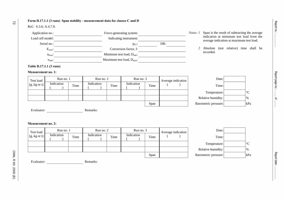
72
Report no.: .....................
Report page no.: .......... of ...........
OIM
L R
60
: 20
00
(E)
Form D.17.1.1 (3 runs) Span stability - measurement data for classes C and D
Ref.: 6.3.6; A.4.7.8.
Application no.: Force-generating system:
Load cell model: Indicating instrument:
Serial no.: pLC: DR:
Emax: Conversion factor, f:
nmax: Minimum test load, Dmin:
vmin: Maximum test load, Dmax:
Notes: 1 Span is the result of subtracting the average indication at minimum test load from the average indication at maximum test load.
2 Absolute (not relative) time shall be
recorded.
Table D.17.1.1 (3 runs)
Measurement no. 1:
Run no. 1 Run no. 2 Run no. 3 Date: Test load (g, kg or t) Indication
( ) Time
Indication ( )
Time Indication ( )
Time
Average indication ( ) Time:
Temperature: °C
Relative humidity: %
Span Barometric pressure: kPa
Evaluator: Remarks: Measurement no. 2:
Run no. 1 Run no. 2 Run no. 3 Date: Test load (g, kg or t) Indication
( ) Time
Indication ( )
Time Indication ( )
Time
Average indication ( ) Time:
Temperature: °C
Relative humidity: %
Span Barometric pressure: kPa
Evaluator: Remarks:
Report date: ....................
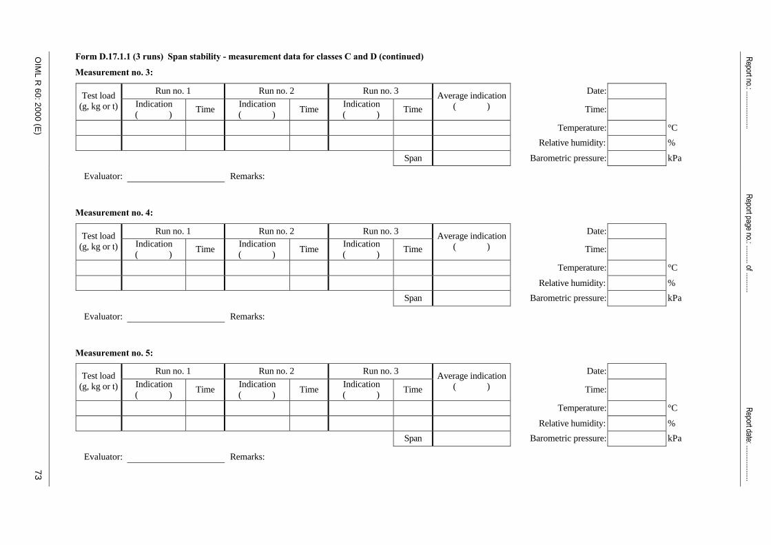
OIM
L R
60
: 20
00
(E)
Report no.: .....................
Report page no.: .......... of ...........
73
Form D.17.1.1 (3 runs) Span stability - measurement data for classes C and D (continued)
Measurement no. 3:
Run no. 1 Run no. 2 Run no. 3 Date: Test load (g, kg or t) Indication
( ) Time
Indication ( )
Time Indication ( )
Time
Average indication ( ) Time:
Temperature: °C
Relative humidity: %
Span Barometric pressure: kPa
Evaluator: Remarks: Measurement no. 4:
Run no. 1 Run no. 2 Run no. 3 Date: Test load (g, kg or t) Indication
( ) Time
Indication ( )
Time Indication ( )
Time
Average indication ( ) Time:
Temperature: °C
Relative humidity: %
Span Barometric pressure: kPa
Evaluator: Remarks: Measurement no. 5:
Run no. 1 Run no. 2 Run no. 3 Date: Test load (g, kg or t) Indication
( ) Time
Indication ( )
Time Indication ( )
Time
Average indication ( ) Time:
Temperature: °C
Relative humidity: %
Span Barometric pressure: kPa
Evaluator: Remarks:
Report date: ....................
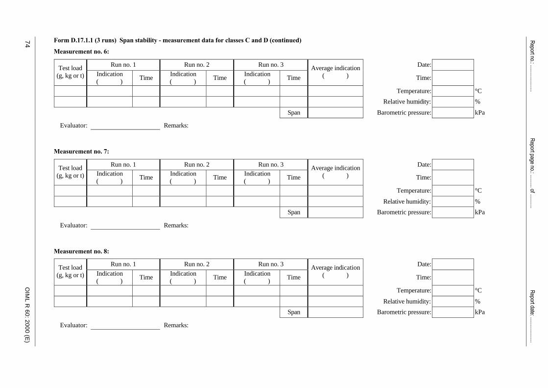
74
Report no.: .....................
Report page no.: .......... of ...........
OIM
L R
60
: 20
00
(E)
Form D.17.1.1 (3 runs) Span stability - measurement data for classes C and D (continued)
Measurement no. 6:
Run no. 1 Run no. 2 Run no. 3 Date: Test load (g, kg or t) Indication
( ) Time
Indication ( )
Time Indication ( )
Time
Average indication ( ) Time:
Temperature: °C
Relative humidity: %
Span Barometric pressure: kPa
Evaluator: Remarks: Measurement no. 7:
Run no. 1 Run no. 2 Run no. 3 Date: Test load (g, kg or t) Indication
( ) Time
Indication ( )
Time Indication ( )
Time
Average indication ( ) Time:
Temperature: °C
Relative humidity: %
Span Barometric pressure: kPa
Evaluator: Remarks: Measurement no. 8:
Run no. 1 Run no. 2 Run no. 3 Date: Test load (g, kg or t) Indication
( ) Time
Indication ( )
Time Indication ( )
Time
Average indication ( ) Time:
Temperature: °C
Relative humidity: %
Span Barometric pressure: kPa
Evaluator: Remarks:
Report date: ....................

OIM
L R
60
: 20
00
(E)
Report no.: .....................
Report page no.: .......... of ...........
75
Form D.17.1.1 (5 runs) Span stability - measurement data for class B
Ref.: 6.3.6; A.4.7.8.
Application no.: Force-generating system:
Load cell model: Indicating instrument:
Serial no.: pLC: DR:
Emax: Conversion factor, f:
nmax: Minimum test load, Dmin:
vmin: Maximum test load, Dmax:
Notes: 1. Span is the result of subtracting the average indication at minimum test load from the average indication at maximum test load.
2. Absolute (not relative) time shall be
recorded.
Table D.17.1.1 (5 runs)
Measurement no. 1:
Run no. 1 Run no. 2 Run no. 3 Run no. 4 Run no. 5 Date: Test load (g, kg or t) Indication
( ) Time
Indication ( )
Time Indication ( )
Time Indication ( )
Time Indication ( )
Time
Average indication ( ) Time:
Temperature: °C
Relative humidity: %
Span Barometric pressure: kPa
Evaluator: Remarks:
Measurement no. 2:
Run no. 1 Run no. 2 Run no. 3 Run no. 4 Run no. 5 Date: Test load (g, kg or t) Indication
( ) Time
Indication ( )
Time Indication ( )
Time Indication ( )
Time Indication ( )
Time
Average indication ( ) Time:
Temperature: °C
Relative humidity: %
Span Barometric pressure: kPa
Evaluator: Remarks:
Report date: ....................
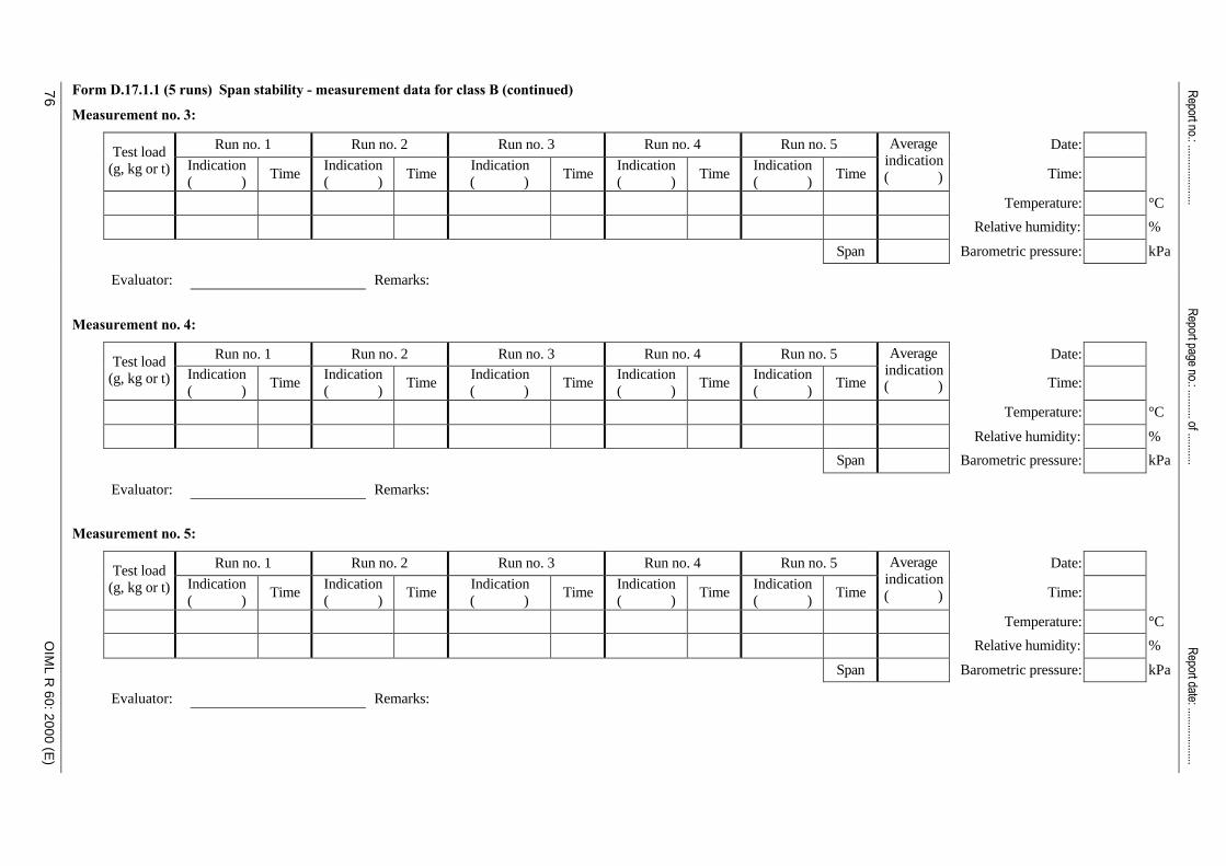
76
Report no.: .....................
Report page no.: .......... of ...........
OIM
L R
60
: 20
00
(E)
Form D.17.1.1 (5 runs) Span stability - measurement data for class B (continued)
Measurement no. 3:
Run no. 1 Run no. 2 Run no. 3 Run no. 4 Run no. 5 Date: Test load (g, kg or t) Indication
( ) Time
Indication ( )
Time Indication ( )
Time Indication ( )
Time Indication ( )
Time
Average indication ( ) Time:
Temperature: °C
Relative humidity: %
Span Barometric pressure: kPa
Evaluator: Remarks:
Measurement no. 4:
Run no. 1 Run no. 2 Run no. 3 Run no. 4 Run no. 5 Date: Test load (g, kg or t) Indication
( ) Time
Indication ( )
Time Indication ( )
Time Indication ( )
Time Indication ( )
Time
Average indication ( ) Time:
Temperature: °C
Relative humidity: %
Span Barometric pressure: kPa
Evaluator: Remarks:
Measurement no. 5:
Run no. 1 Run no. 2 Run no. 3 Run no. 4 Run no. 5 Date: Test load (g, kg or t) Indication
( ) Time
Indication ( )
Time Indication ( )
Time Indication ( )
Time Indication ( )
Time
Average indication ( ) Time:
Temperature: °C
Relative humidity: %
Span Barometric pressure: kPa
Evaluator: Remarks:
Report date: ....................

OIM
L R
60
: 20
00
(E)
Report no.: .....................
Report page no.: .......... of ...........
77
Form D.17.1.1 (5 runs) Span stability - measurement data for class B (continued)
Measurement no. 6:
Run no. 1 Run no. 2 Run no. 3 Run no. 4 Run no. 5 Date: Test load (g, kg or t) Indication
( ) Time
Indication ( )
Time Indication ( )
Time Indication ( )
Time Indication ( )
Time
Average indication ( ) Time:
Temperature: °C
Relative humidity: %
Span Barometric pressure: kPa
Evaluator: Remarks:
Measurement no. 7:
Run no. 1 Run no. 2 Run no. 3 Run no. 4 Run no. 5 Date: Test load (g, kg or t) Indication
( ) Time
Indication ( )
Time Indication ( )
Time Indication ( )
Time Indication ( )
Time
Average indication ( ) Time:
Temperature: °C
Relative humidity: %
Span Barometric pressure: kPa
Evaluator: Remarks:
Measurement no. 8:
Run no. 1 Run no. 2 Run no. 3 Run no. 4 Run no. 5 Date: Test load (g, kg or t) Indication
( ) Time
Indication ( )
Time Indication ( )
Time Indication ( )
Time Indication ( )
Time
Average indication ( ) Time:
Temperature: °C
Relative humidity: %
Span Barometric pressure: kPa
Evaluator: Remarks:
Report date: ....................
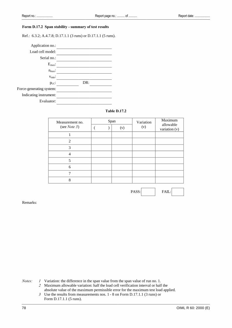
Report no.: ..................... Report page no.: .......... of ........... Report date: ....................
78 OIML R 60: 2000 (E)
Form D.17.2 Span stability - summary of test results Ref.: 6.3.2; A.4.7.8; D.17.1.1 (3 runs) or D.17.1.1 (5 runs).
Application no.:
Load cell model:
Serial no.:
Emax:
nmax:
vmin:
pLC: DR:
Force-generating system:
Indicating instrument:
Evaluator:
Table D.17.2
Span Measurement no. (see Note 3) ( ) (v)
Variation (v)
Maximum allowable
variation (v)
1
2
3
4
5
6
7
8
PASS: FAIL:
Remarks:
Notes: 1 Variation: the difference in the span value from the span value of run no. 1. 2 Maximum allowable variation: half the load cell verification interval or half the
absolute value of the maximum permissible error for the maximum test load applied. 3 Use the results from measurements nos. 1 - 8 on Form D.17.1.1 (3 runs) or
Form D.17.1.1 (5 runs).

OIML R 60: 2000 (E)
79Page 1. This certificate includes ....... pages.
Annex E(Mandatory)
OIML Certificate of conformity for load cells
E.1 Format of certificate
Member State OIML CERTIFICATE OF CONFORMITY OIML certificate no.
_______________________ _______________________
Issuing AuthorityName: ...............................................................................................................................................................................Address: ............................................................................................................................................................................Person responsible: ..........................................................................................................................................................
ApplicantName: ...............................................................................................................................................................................Address: ............................................................................................................................................................................Manufacturer of the certified pattern (if the manufacturer is not the applicant) ......................................................................Identification of the certified pattern: Load cell (construction principle, for example, strain gauge, compression, etc.)
...........................................................................................................................................................................................
Model designation
Maximum capacity, Emax
Accuracy class
Maximum number of load cellverification intervals, nmax
Minimum verification interval, vmin
Apportionment factor, pLC
(Additional characteristics and identification, as applicable according to R 60, 2.2.3 and 4.6, continued overleaf or on addendum if necessary)
This certificate attests the conformity of the above-mentioned pattern (represented by the samples identified inthe associated test report(s) with the requirements of the following Recommendation of the InternationalOrganization of Legal Metrology - OIML):
R 60 Metrological regulation for load cells Edition ....................... for accuracy class ...............................................
This certificate relates only to the metrological and technical characteristics of the pattern of instrumentconcerned, as covered by the relevant OIML International Recommendation.
This certificate does not bestow any form of legal international approval.
The conformity was established by tests described in the associated test report no. ……, which includes ……. pages.
Identification(s) and signature(s) or stamp(s), of (as applicable):
Issuing Authority: CIML Member:
Date: .......................................Date: .......................................
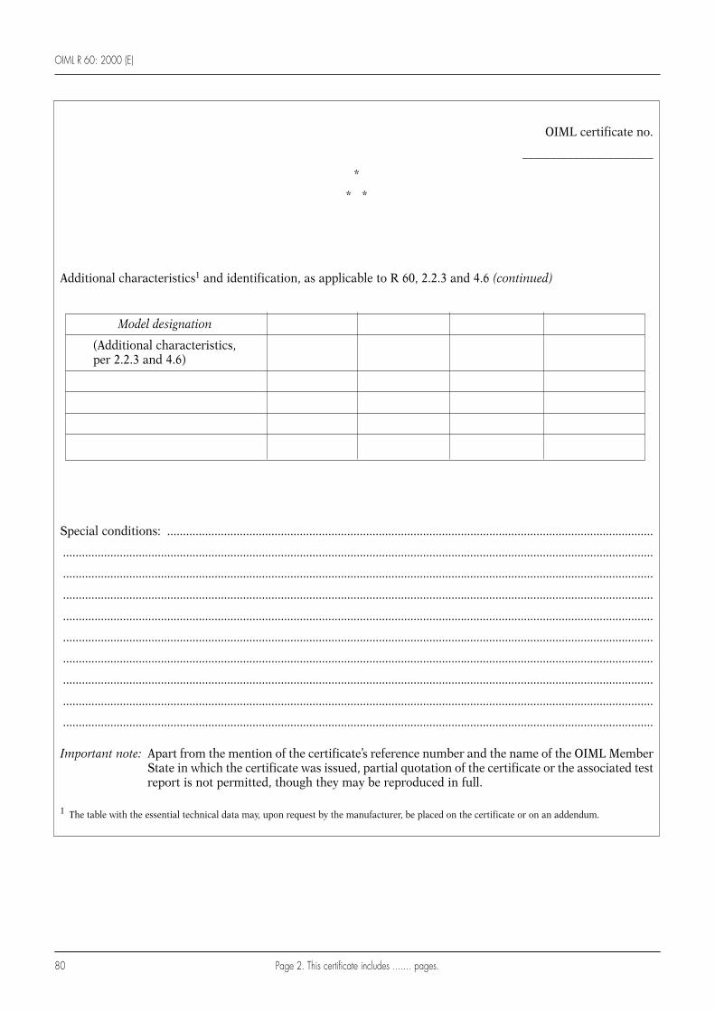
OIML R 60: 2000 (E)
80
OIML certificate no.
_______________________
*
* *
Additional characteristics1 and identification, as applicable to R 60, 2.2.3 and 4.6 (continued)
Special conditions: ..........................................................................................................................................................
...........................................................................................................................................................................................
...........................................................................................................................................................................................
...........................................................................................................................................................................................
...........................................................................................................................................................................................
...........................................................................................................................................................................................
...........................................................................................................................................................................................
...........................................................................................................................................................................................
...........................................................................................................................................................................................
...........................................................................................................................................................................................
Important note: Apart from the mention of the certificate’s reference number and the name of the OIML MemberState in which the certificate was issued, partial quotation of the certificate or the associated testreport is not permitted, though they may be reproduced in full.
1 The table with the essential technical data may, upon request by the manufacturer, be placed on the certificate or on an addendum.
Model designation
(Additional characteristics,per 2.2.3 and 4.6)
Page 2. This certificate includes ....... pages.
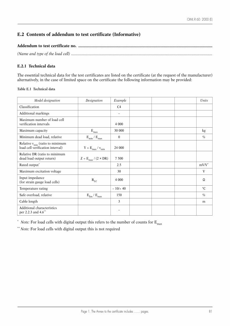
OIML R 60: 2000 (E)
81
E.2 Contents of addendum to test certificate (Informative)
Addendum to test certificate no. ............................................................................................................................
(Name and type of the load cell) ...........................................................................................................................................
E.2.1 Technical data
The essential technical data for the test certificates are listed on the certificate (at the request of the manufacturer)alternatively, in the case of limited space on the certificate the following information may be provided:
Table E.1 Technical data
Model designation Designation Example Units
Classification C4
Additional markings –
Maximum number of load cell verification intervals 4 000
Maximum capacity Emax 30 000 kg
Minimum dead load, relative Emin / Emax 0 %
Relative vmin (ratio to minimum load cell verification interval) Y = Emax / vmin 24 000
Relative DR (ratio to minimum dead load output return) Z = Emax / (2 × DR) 7 500
Rated output* 2.5 mV/V*
Maximum excitation voltage 30 V
Input impedance (for strain gauge load cells)
RLC 4 000 Ω
Temperature rating – 10/+ 40 °C
Safe overload, relative Elim / Emax 150 %
Cable length 3 m
Additional characteristics per 2.2.3 and 4.6** –
* Note: For load cells with digital output this refers to the number of counts for Emax
** Note: For load cells with digital output this is not required
Page 1. The Annex to the certificate includes ....... pages.

OIML R 60: 2000 (E)
82
E.2.2 Tests
The tests listed in Table E.2 have been carried out in accordance with OIML R 60:
- at the laboratory .............................................................................................. (insert laboratory name)
- as documented in the test report no. ............................................................. (insert test report number)
Table E.2 Tests performed with load cell:
Serial no.: .............................................................................................................................................................................
Class: .....................................................................................................................................................................................
Emax: ......................................................................................................................................................................................
nmax: ......................................................................................................................................................................................
Y: ...........................................................................................................................................................................................
Z: ...........................................................................................................................................................................................
Test R 60 Ref. Approved Institute
Temperature test and repeatability at 20 °C, 40 °C, – 10 °C, 20 °C 5.1.1, 5.4; A.4.1
Temperature effect on minimum dead load output at 20 °C, 40 °C, – 10 °C, 20 °C 5.5.1.3; A.4.1
Creep at 20 °C, 40 °C, – 10 °C 5.3.1; A.4.2
Minimum dead load output return at 20 °C, 40 °C, – 10 °C 5.3.2; A.4.3
Barometric pressure effects at room temperature 5.5.2; A.4.4
Damp heat, cyclic: marked CH (or not marked) 5.5.3.1; A.4.5
Damp heat, steady state:marked SH 5.5.3.2; A.4.6
Additional tests for load cells equipped with electronics 6; A.4.7
Warm-up time 6.3.2; A.4.7.2
Power voltage variations 6.3.3, 6.3.4; A.4.7.3
Short time power reductions 6.3.5; A.4.7.4
Bursts (electrical fast transients) 6.3.5; A.4.7.5
Electrostatic discharge 6.3.5; A.4.7.6
Electromagnetic susceptibility 6.3.5; A.4.7.7
Span stability 6.3.6; A.4.7.8
Page 2. The Annex to the certificate includes ....... pages.

OIML R 60: 2000 (E)
83
Index of terms
Accuracy class ............................................................................... 2.2.1
Application of load ....................................................................... 2.1.1
Apportionment factor (pLC) .......................................................... 2.4.2
Compression loading ................................................................. 2.1.1.1
Creep .............................................................................................. 2.4.1
Disturbance ................................................................................ 2.5.1.1
Electronic component ............................................................... 2.1.3.1
Expanded uncertainty .................................................................. 2.4.3
Fault ............................................................................................... 2.4.4
Fault detection output .................................................................. 2.4.5
General terms ................................................................................... 2.1
Humidity symbol .......................................................................... 2.2.2
Hysteresis error ............................................................................. 2.4.6
Illustration of certain definitions .................................................... 2.6
Influence factor .......................................................................... 2.5.1.2
Influence quantity ......................................................................... 2.5.1
Influences and reference conditions .............................................. 2.5
Load cell ........................................................................................ 2.1.2
Load cell equipped with electronics ............................................ 2.1.3
Load cell error ............................................................................... 2.4.7
Load cell family ............................................................................. 2.2.3
Load cell group .......................................................................... 2.2.3.1
Load cell interval .......................................................................... 2.3.1
Load cell intrinsic error ................................................................ 2.4.8
Load cell measuring range ........................................................... 2.3.2
Load cell output ............................................................................ 2.3.3
Load cell verification interval (v) ................................................. 2.3.4
Maximum capacity (Emax) ............................................................ 2.3.5
Maximum load of the measuring range (Dmax) .......................... 2.3.6
Maximum number of load cell verification intervals (nmax) ...... 2.3.7
Maximum permissible error (mpe) ............................................. 2.4.9
Maximum test load ................................................................... A.3.2.4
Measurement and error terms ........................................................ 2.4
Metrological characteristics of a load cell ..................................... 2.2
Minimum dead load (Emin) .......................................................... 2.3.8
Minimum dead load output return (DR) .................................... 2.3.9
Minimum load cell verification interval (vmin) ......................... 2.3.10
Minimum load of the measuring range (Dmin) ......................... 2.3.11
Minimum test load ................................................................... A.3.2.4
Non-linearity ............................................................................... 2.4.10
Number of load cell verification intervals (n) ........................... 2.3.12
Performance test ........................................................................... 2.1.4
Range, capacity and output terms .................................................. 2.3
Rated operating conditions .......................................................... 2.5.2
Reference conditions .................................................................... 2.5.3
Relative DR or Z ......................................................................... 2.3.13
Relative vmin or Y ........................................................................ 2.3.14
Repeatability ............................................................................... 2.4.11
Repeatability error ...................................................................... 2.4.12
Safe load limit ............................................................................. 2.3.15
Sensitivity .................................................................................... 2.4.13
Significant fault .......................................................................... 2.4.14
Span stability .............................................................................. 2.4.15
Temperature effect on minimum dead load output ................. 2.4.16
Temperature effect on sensitivity ............................................... 2.4.17
Tension loading .......................................................................... 2.1.1.2
Warm-up time ............................................................................. 2.3.16

Printed in France GRANDE IMPRIMERIE DE TROYES