Embed Size (px)
Citation preview
Formula SAE Electric Drive Control
Design Team 05
Nick Ga1a Alex Klein
Alex Spickard Tyler Zoner
Faculty Advisor: Dr. Sozer
Need
• This Drive Control System must enable a driver to be competitive on the racetrack in both speed and efficiency.
• Adherence to these rules ensures that the vehicle is safe, and is required to foster fair competition.
2
Objective
• Design an intelligent Drive Control System • Implement torque vectoring • Implement traction control • Deliver as much power as possible from
batteries
• Follow all guidelines provided by Society of Automotive Engineers (SAE)
• Create a safe and successful vehicle
3
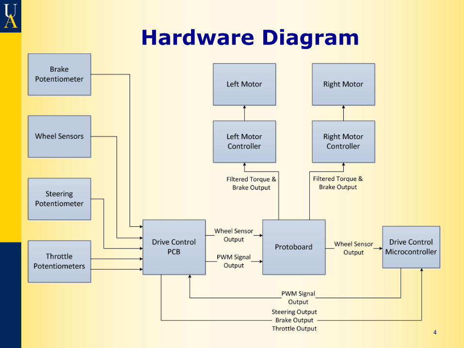
Hardware Diagram
4
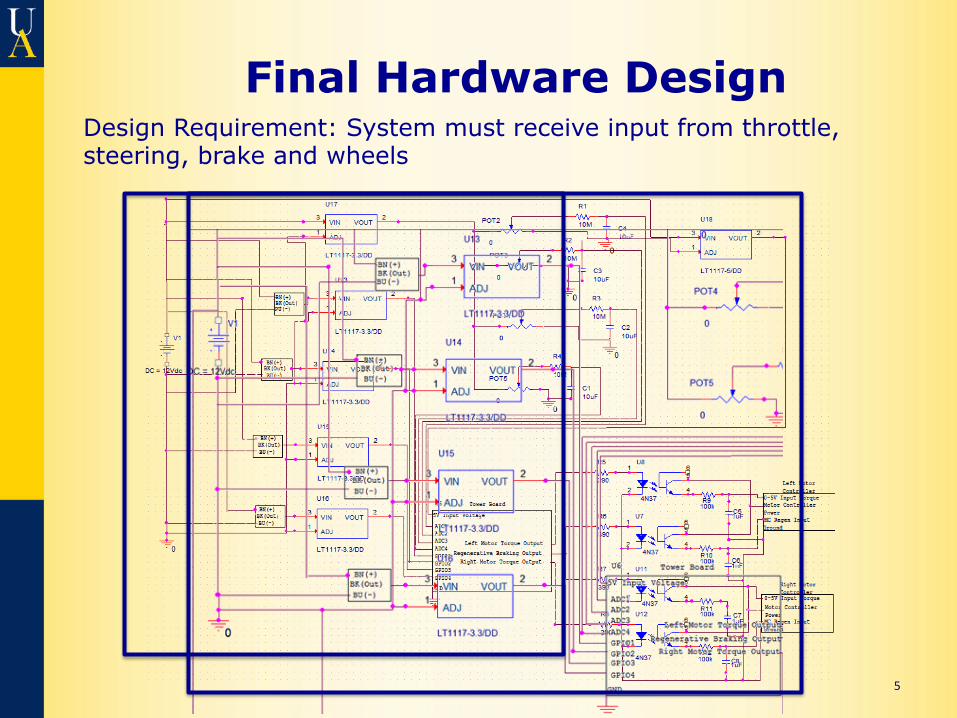
Final Hardware Design
5
Design Requirement: System must receive input from throttle, steering, brake and wheels
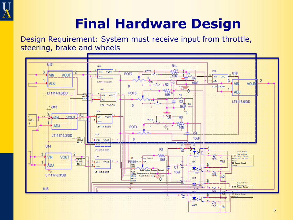
Final Hardware Design
6
Design Requirement: System must receive input from throttle, steering, brake and wheels
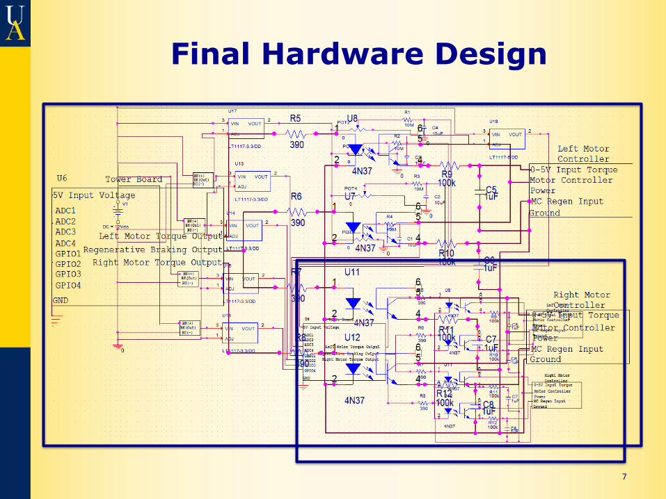
Final Hardware Design
7
Wheel Sensors
8
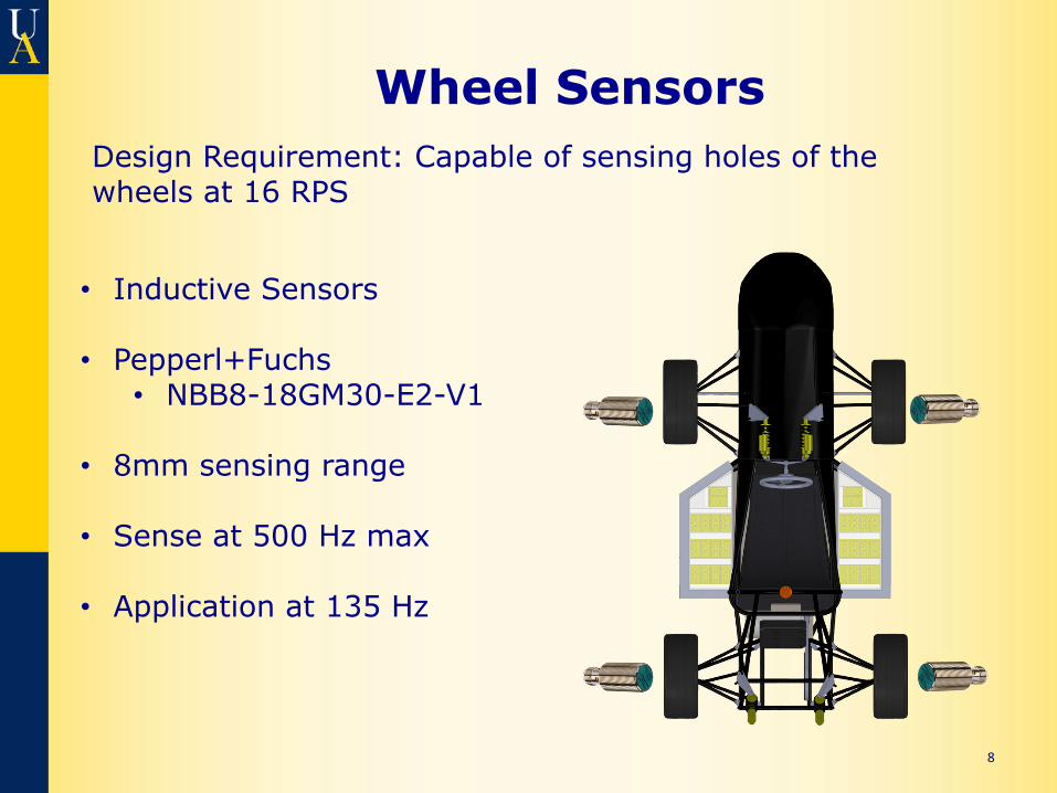
• Inductive Sensors
• Pepperl+Fuchs • NBB8-18GM30-E2-V1
• 8mm sensing range • Sense at 500 Hz max
• Application at 135 Hz
Design Requirement: Capable of sensing holes of the wheels at 16 RPS
Driver Inputs
9
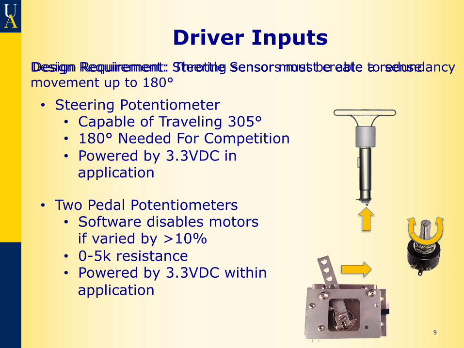
• Steering Potentiometer • Capable of Traveling 305° • 180° Needed For Competition • Powered by 3.3VDC in
application
Design Requirement: Steering sensor must be able to sense movement up to 180° Design Requirement: Throttle Sensors must create a redundancy
• Two Pedal Potentiometers • Software disables motors
if varied by >10% • 0-5k resistance • Powered by 3.3VDC within
application
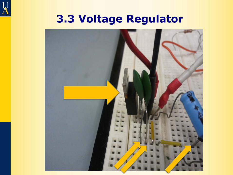
3.3 Voltage Regulator
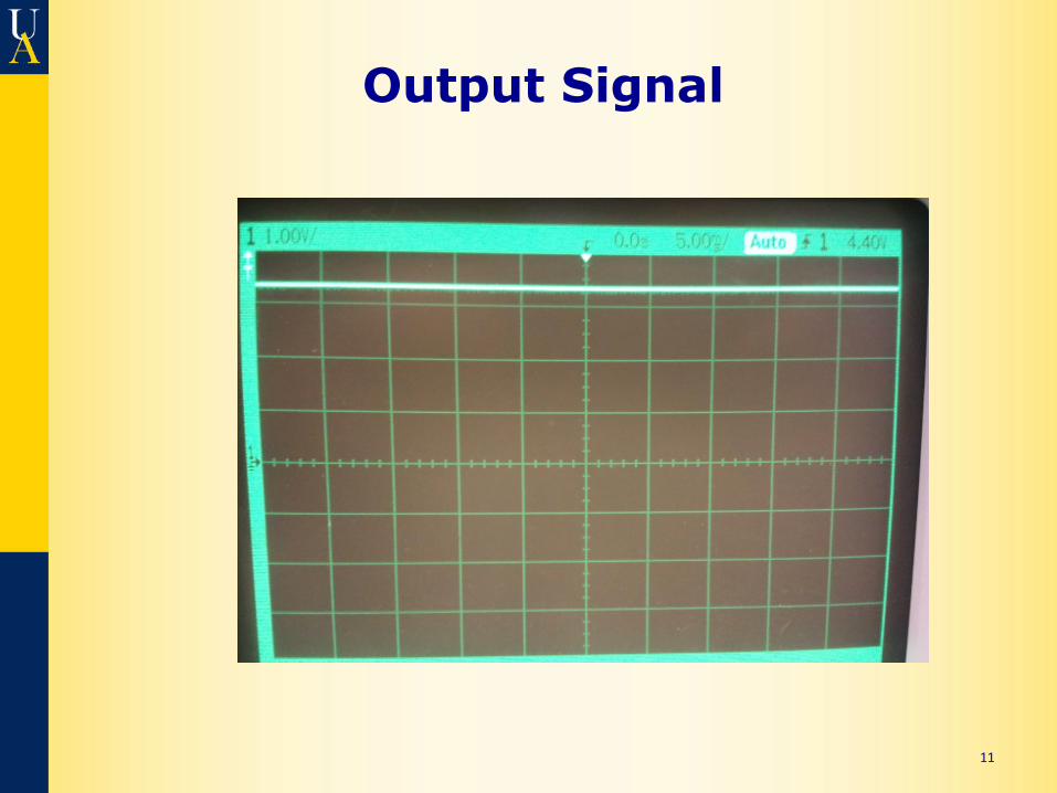
Output Signal
11
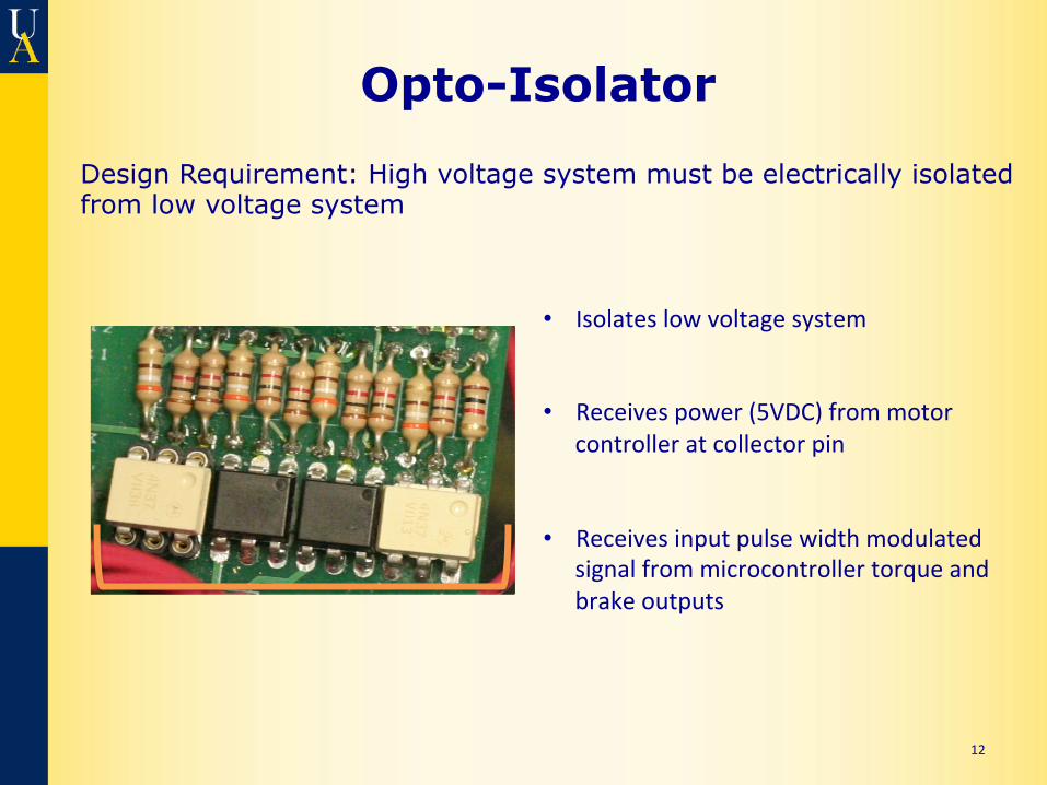
Opto-Isolator
12
• Isolates low voltage system
• Receives power (5VDC) from motor controller at collector pin
• Receives input pulse width modulated signal from microcontroller torque and brake outputs
Design Requirement: High voltage system must be electrically isolated from low voltage system
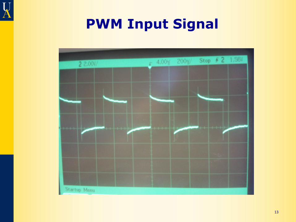
PWM Input Signal
13
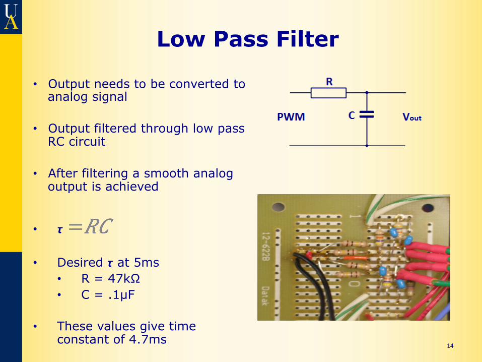
Low Pass Filter
14
• Output needs to be converted to analog signal
• Output filtered through low pass RC circuit
• After filtering a smooth analog output is achieved
• 𝞽 =𝑅𝐶 =𝑅𝐶
• Desired 𝞽 at 5ms • R = 47kΩ • C = .1µF
• These values give time
constant of 4.7ms
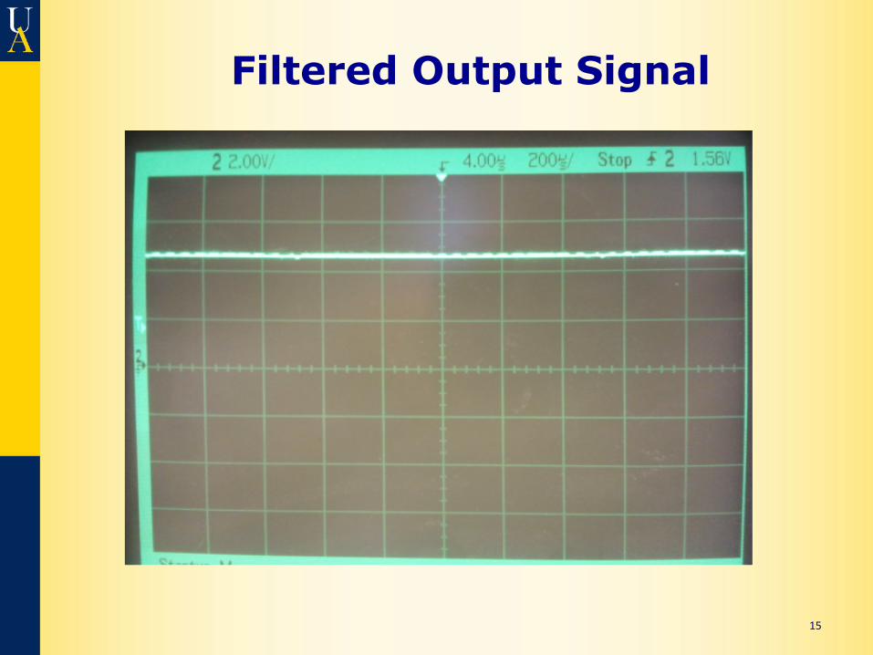
Filtered Output Signal
15
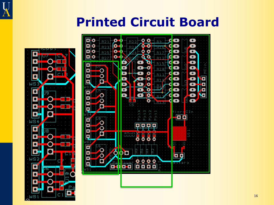
Printed Circuit Board
16
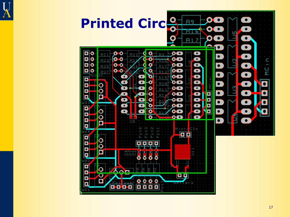
Printed Circuit Board
17
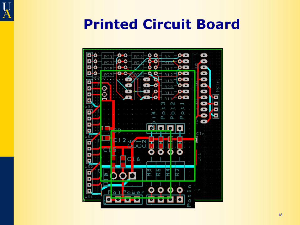
Printed Circuit Board
18
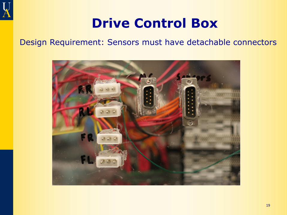
Drive Control Box
19
Design Requirement: Sensors must have detachable connectors
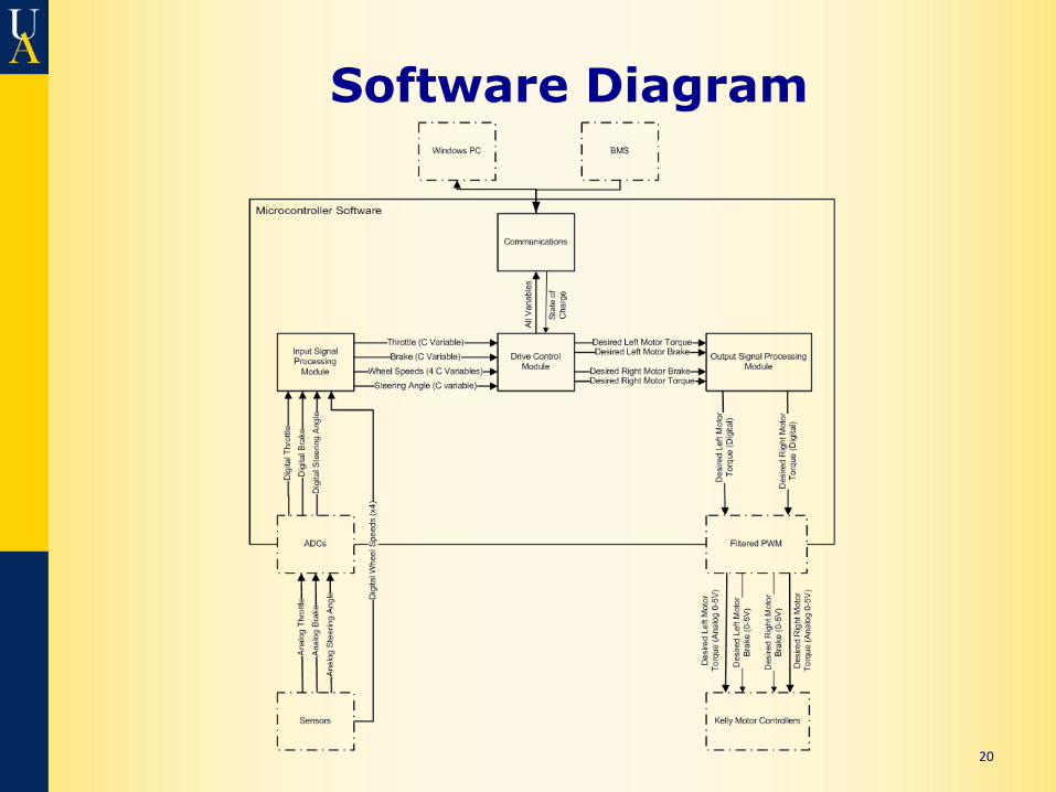
Software Diagram
20
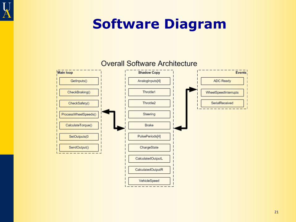
Software Diagram
21

Software Flow
22
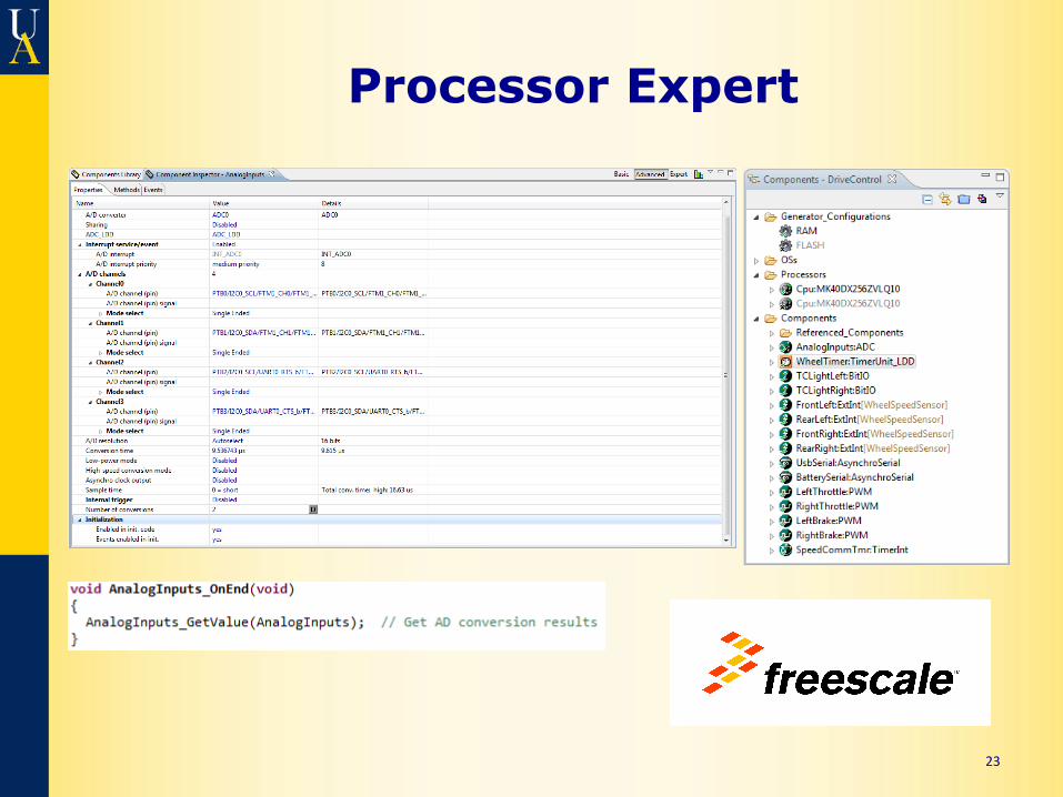
Processor Expert
23
Efficient Control Design Requirement: System must use limited power available efficiently.
• Motors are ~90% efficient, controllers are 99% efficient
• Traction Control and Torque Vectoring prevent unnecessary wheel spin and keep power evenly distributed to each motor
• Torque output maximum is lowered as battery charge decreases
24
Regeneration
Design Requirement: Regenerating energy is not allowed at or below 5 km/h.
• Wheel speed sensors are used to measure overall vehicle speed
• Software puts regenerative outputs at 0 when speed is less than 3 m/s (10.8km/h) to be safe
25
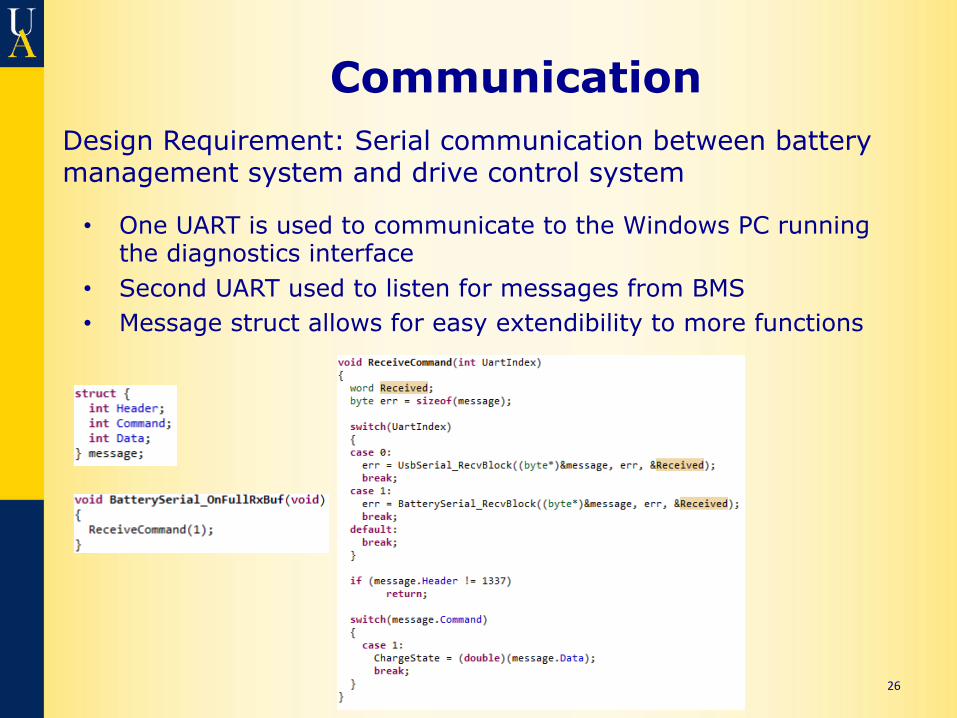
Communication
• One UART is used to communicate to the Windows PC running the diagnostics interface
• Second UART used to listen for messages from BMS • Message struct allows for easy extendibility to more functions
26
Design Requirement: Serial communication between battery management system and drive control system
User Display
Design Requirements: System must process inputs and provide information to user display
• Dash display for car is currently unfinished
• Current code outputs all of the required information to a UART that is currently connected to a Windows diagnostics application
27
Traction Control
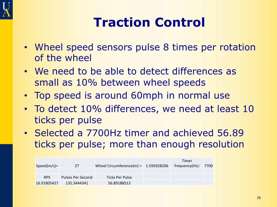
• Wheel speed sensors pulse 8 times per rotation of the wheel
• We need to be able to detect differences as small as 10% between wheel speeds
• Top speed is around 60mph in normal use • To detect 10% differences, we need at least 10
ticks per pulse • Selected a 7700Hz timer and achieved 56.89
ticks per pulse; more than enough resolution
28
Speed(m/s)= 27 Wheel Circumference(m) = 1.595928206 Timer
frequency(Hz): 7700
RPS Pulses Per Second Ticks Per Pulse 16.91805427 135.3444341 56.89188513
Torque Vectoring
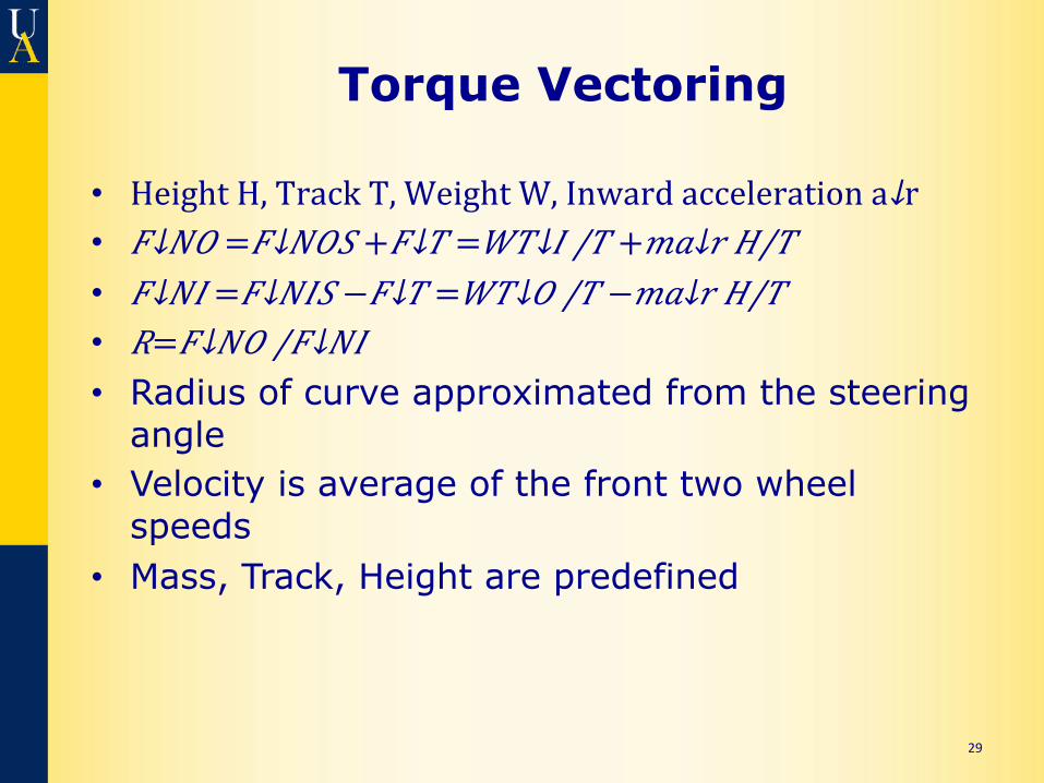
• Height H, Track T, Weight W, Inward acceleration a↓r • 𝐹↓𝑁𝑂 = 𝐹↓𝑁𝑂𝑆 + 𝐹↓𝑇 = 𝑊𝑇↓𝐼 /𝑇 + 𝑚𝑎↓𝑟 𝐻/𝑇 • 𝐹↓𝑁𝐼 = 𝐹↓𝑁𝐼𝑆 − 𝐹↓𝑇 = 𝑊𝑇↓𝑂 /𝑇 − 𝑚𝑎↓𝑟 𝐻/𝑇 • 𝑅= 𝐹↓𝑁𝑂 /𝐹↓𝑁𝐼 • Radius of curve approximated from the steering
angle • Velocity is average of the front two wheel
speeds • Mass, Track, Height are predefined
29
Torque Vectoring
30
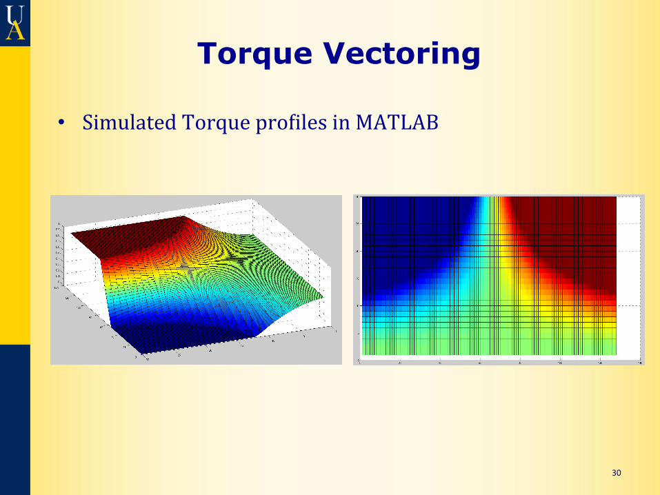
• Simulated Torque pro?iles in MATLAB
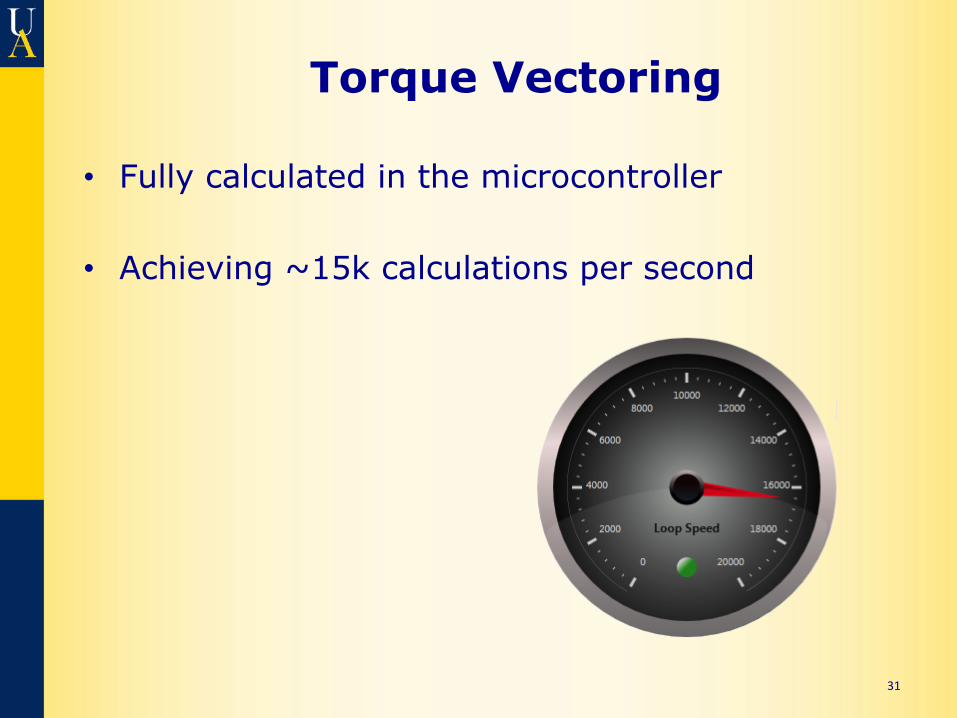
Torque Vectoring
• Fully calculated in the microcontroller
• Achieving ~15k calculations per second
31
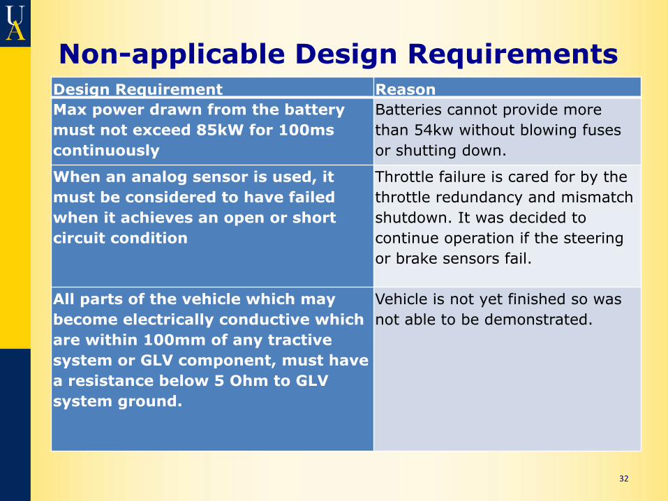
Non-applicable Design Requirements Design Requirement Reason Max power drawn from the battery must not exceed 85kW for 100ms continuously
Batteries cannot provide more than 54kw without blowing fuses or shutting down.
When an analog sensor is used, it must be considered to have failed when it achieves an open or short circuit condition
Throttle failure is cared for by the throttle redundancy and mismatch shutdown. It was decided to continue operation if the steering or brake sensors fail.
All parts of the vehicle which may become electrically conductive which are within 100mm of any tractive system or GLV component, must have a resistance below 5 Ohm to GLV system ground.
Vehicle is not yet finished so was not able to be demonstrated.
32
Conclusion
• We have built an easily extensible system to serve as a foundation for the future of the UA FSAE Electric team.
• Any questions?
33