Embed Size (px)
Citation preview

Get Your Head Out of the Point Cloud: Using AutoCAD® Civil 3D® for Large Surface Datasets
Dana Breig Probert, Autodesk, Inc.
CV218-1L These days, we seem to be buried in data -- but how much data is too much? It's often difficult enough to open our data files, let alone build a meaningful TIN surface from them. We know we need to use high-tech field-collection information, such as LIDAR, Aerial Topography, and GPS points, so let's figure out a way to use it with the software and computer systems we currently have in our office.
About the Speaker: Dana received her Bachelor of Science in Civil Engineering from Georgia Tech in 1998. Since then she has worked on a variety of civil projects in the U.S. and Canada, using Land Desktop, Civil Design, Raster Design, Map 3D and Civil 3D. In addition, Dana has helped many firms with their Civil 3D pilot projects and implementation plans. Dana has been an instructor at Autodesk University for the past three years, worked on Autodesk courseware projects, and is coauthor of the books, “Mastering AutoCAD Civil 3D 2008”, “Mastering AutoCAD Civil 3D 2009”, and “Introducing Civil 3D 2009”. Dana maintains the Civil 3D Rocks blog at www.civil3drocks.com.

Get Your Head Out of the Point Cloud
2
Get Your Head Out of the Point Cloud
3
Get Your Head Out Of the (Point) Cloud! We’ve all struggled with massive surfaces… You spend all day trying to import the data without locking your machine. Once you finally succeed in getting the points into the drawing, you find yourself crashing when you build the surface, or dealing with painfully slow regeneration times.
The goal of this class is to provide you with some plain and simple techniques for filtering through the chaff and digging into the wheat to build a great surface. These ideas and techniques may not be terribly flashy or high tech, but I find that they work for most large surface applications such as large point files, LIDAR data and aerial topographic data. Many techniques in this class can also be applied to other Civil 3D objects and applications.
Building Surfaces from Typical Large Datasets Three extremely common large surface datasets are point files, LIDAR contours and aerial topographic information.
Large point files might come from a state agency, internet site or perhaps from privately contracted LIDAR work. These files are typically text files in the format of .txt or similar. The points used in this presentation come from North Carolina Flood Mapping. There are lots of publically available LIDAR point files. Try Google to search, or your state’s geospatial data clearinghouse.
LIDAR contours are typically the export of some sort of LIDAR post processing software. Instead of sharing the large point files, someone has converted the data into a terrain model and exported the contours as polylines in an AutoCAD drawing. There are lots of publically available LIDAR contour files. Try Google to search, or your state’s geospatial data clearinghouse.
Aerial Topographic Data is typically privately contracted. The aerial topography company will often provide two drawings. The first drawing will contain contours, features and labeling. The second drawing will contain points and breaklines. These companies can often provide you with other formats upon request.
Get Your Head Out of the Point Cloud
4
Best Practices? What is best practice for me could be completely wrong for you. Conventional wisdom on the use of Civil 3D is constantly evolving. For me, I like to share information because it starts a dialog and encourages others to share their approach. The techniques in this presentation are intended to assist you in opening the Civil 3D bag of tricks and launch you on your own journey to discovering your own Best Practices.
Much of work that is ongoing is documented on blogs and the Autodesk discussion groups, so become a regular reader, and when you feel ready, a contributor.
The Truth About Hardware If you are working with large surface datasets, it may seem like buying the most expensive computer out there with the most muscle would be all you need for success.
The truth is that a lot of the limitations on large surface datasets are not hardware related, but limitations from Civil 3D itself. There are, however, some hardware elements that can help.
A lot of people ask me for advice when spec’ing a new system. I’m not a hardware geek, so I can’t tell you what is best for you. But I can tell you what has worked for me and what I have learned through asking questions and observing hundreds of workstations where Civil 3D is installed.
Minimum Specifications Yes. You need AT least the following (from the Autodesk website http://usa.autodesk.com/adsk/servlet/index?siteID=123112&id=8915326 ):
AutoCAD® Civil and AutoCAD® Civil 3D® 2009 Recommended System Requirements
Recommended configuration (excluding server components used with project management capabilities):
Intel® Pentium® 4 (3 GHz or higher); AMD Athlon™; multiple processors supported, dual-core supported
32-bit only: Microsoft® Windows Vista® Ultimate/Business/Enterprise, Microsoft® Windows XP (SP2)
Note: Windows XP 64 and Windows Vista 64 are supported in 32-bit compatibility mode only.
3 GB RAM 5 GB free disk space for installation 1,280 x 1,024 display with true color, 1,600 x 1,200 or greater recommended (OpenGL®
accelerator with full OGL ICD support not required) Microsoft® Internet Explorer® 6.0 (SP1 or later) DVD drive
Get Your Head Out of the Point Cloud
5
√ Note: All of the following refer to work with systems running Windows XP.
Because someone will ask… My specifications on my office desktop machine:
HP xw4600 Workstation Intel Core 2 DuoE6850 3.00 GHz 2.98 GB of RAM NVIDIA Quadro FX 1700 (512 MB)
My specifications on the laptop used to give this presentation:
IBM lenovo T61p Intel Core 2 Duo T7700 2.40 GHz 2.98 GB of RAM NVIDIA Quadro FX 570M (512 MV)
Dual/Quad Core Processors Civil 3D 2009 doesn’t take full advantage of multicore processors. Multicore processors will help with multitasking, such as keeping your stormwater software running while using Civil 3D.
Civil 3D is built on AutoCAD, and some AutoCAD functions, such as rendering, will take advantage of the multiple cores. Also, you may see some improvement in regeneration, zooming, and a few other operations if you adjust your WHIPTHREAD variable. Search Help for more information on WHIPTHREAD.
Verdict: Yes on new machines, but don’t rush out to get one right now.
Video Cards I noticed a real improvement when I upgraded to my current video cards, and I have heard the same from many other users. Anecdotally, we all notice better real time panning and zooming, more stability in 3D views and just fewer visual hiccups. Check out the Autodesk website for a list of certified cards and read the Help file and online resources for proper tuning and configuration (3DCONFIG).
√ Before you upgrade you card, experiment with tuning your current card. Sometimes that is enough to make a difference.
Verdict: Properly tuned, workstation class video cards make a difference. It is worth replacing yours and buying the best you can afford on new machines.

Get Your Head Out of the Point Cloud
6
Ram I personally noticed a difference in processing time when I added more ram to my desktop machine. Be sure to read the article called “The 3 GB Switch and Civil 3D” which can be obtained here: http://usa.autodesk.com/getdoc/id=TS1071001. The future of all software seems to point towards more ram, so don’t skimp on new machines.
Verdict: Ram is cheap. Add more to your current system and be sure to leave lots of room for expansion on new systems.
Civil 3D Limitations for Large Surfaces Civil 3D 2009 has a much greater surface handling capacity than its predecessors, however I still stand by this statement….
“Try to keep it under a million points per surface, and make sure they are a meaningful million.”
-Dana Breig Probert, no warranty implied.
Get Your Head Out of the Point Cloud
7
Building Surfaces from Point Based Data
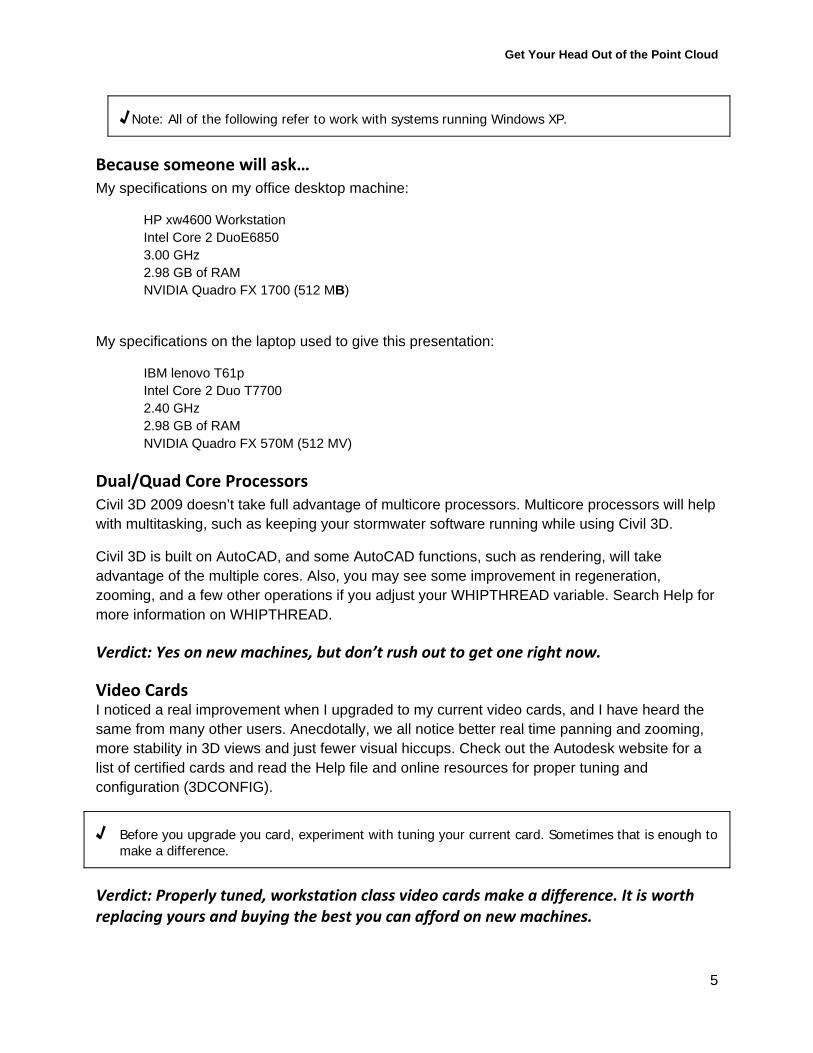
What are TIN points? TIN points are data points or vertices used to build the surface. Every bit of data added to the surface contributes points. For example, the location of a COGO point would be a TIN point, or the vertices of a breakline. You can get a feel for TIN points by turning on points in your Surface style display tab.
The “+” shapes represent TIN points at triangle vertices.
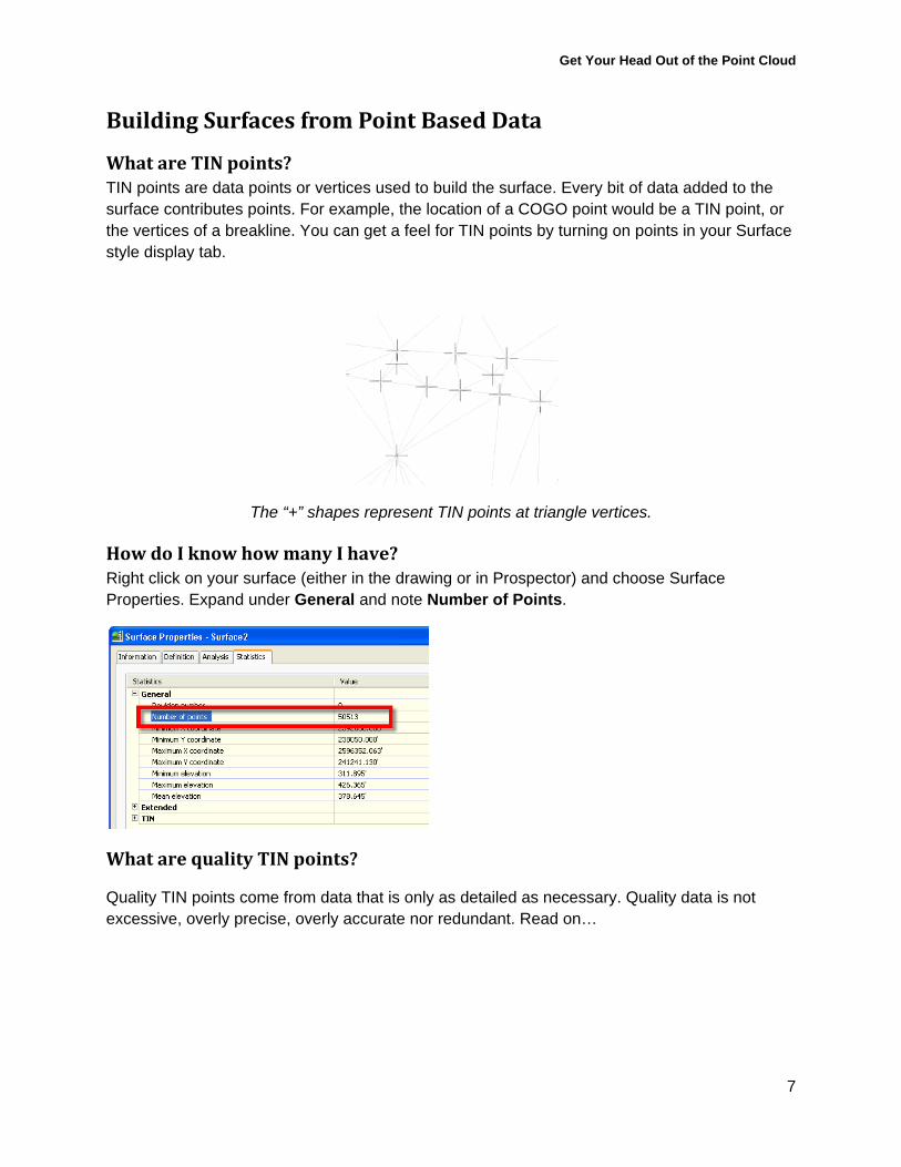
How do I know how many I have? Right click on your surface (either in the drawing or in Prospector) and choose Surface Properties. Expand under General and note Number of Points.
What are quality TIN points?
Quality TIN points come from data that is only as detailed as necessary. Quality data is not excessive, overly precise, overly accurate nor redundant. Read on…
Get Your Head Out of the Point Cloud
8
I Paid Good Money For These Points and I’m Gonna Use Every Stinkin’ One of Them! In Civil 3D, the surface game isn’t so much “How do I use all of this data in Civil 3D?” as “What is the minimum amount of data I can live with?” That can be hard to swallow if you’ve been sold the promise of super duper precision.
Ask yourself:
1. What is the intended purpose of this plan? 2. What is the desired accuracy for vertical information? 3. What is the terrain like? Hilly? Flat? 4. If I had sent a crew out in the field, what kind of accuracy would I expect? How much
precision? Does this project require more or less?
Spend some time with your surveyor, your legal counsel, with industry guidebooks such as those found in the References section at the end of this paper. Figure out exactly what you need versus what would be nice.
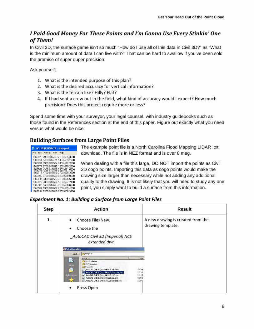
Building Surfaces from Large Point Files The example point file is a North Carolina Flood Mapping LIDAR .txt download. The file is in NEZ format and is over 8 meg.
When dealing with a file this large, DO NOT import the points as Civil 3D cogo points. Importing this data as cogo points would make the drawing size larger than necessary while not adding any additional quality to the drawing. It is not likely that you will need to study any one point, you simply want to build a surface from this information.
Experiment No. 1: Building a Surface from Large Point Files
Step Action Result
1. Choose File>New.
Choose the
_AutoCAD Civil 3D (Imperial) NCS extended.dwt
Press Open
A new drawing is created from the drawing template.
Get Your Head Out of the Point Cloud
9
Step Action Result
2. Choose Surfaces > Create Surface
In the create Surface dialog:
Name the surface Existing Ground Exercise 1
Select the _No Display style
Press OK
A new, empty surface is created in Prospector.
3. In Prospector:
Expand the surface definition
Right‐click in Point Files
Choose Add…
The Add Point File dialog will appear.
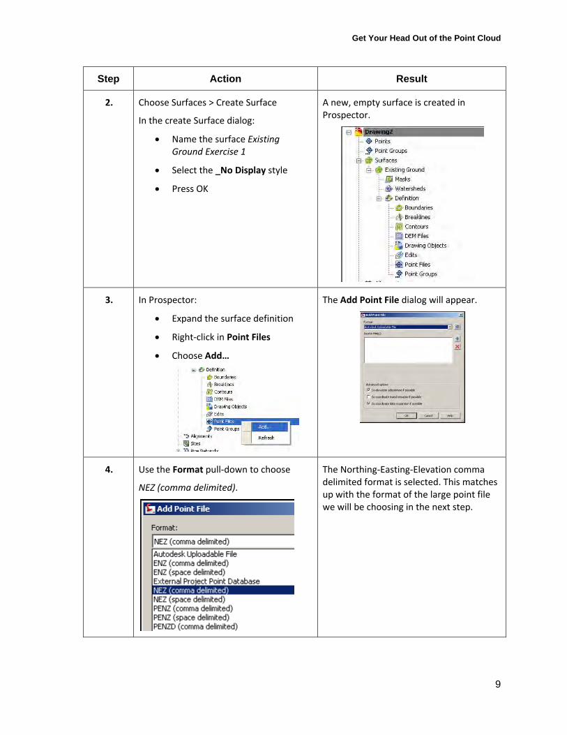
4. Use the Format pull‐down to choose
NEZ (comma delimited).
The Northing‐Easting‐Elevation comma delimited format is selected. This matches up with the format of the large point file we will be choosing in the next step.
Get Your Head Out of the Point Cloud
10
Step Action Result
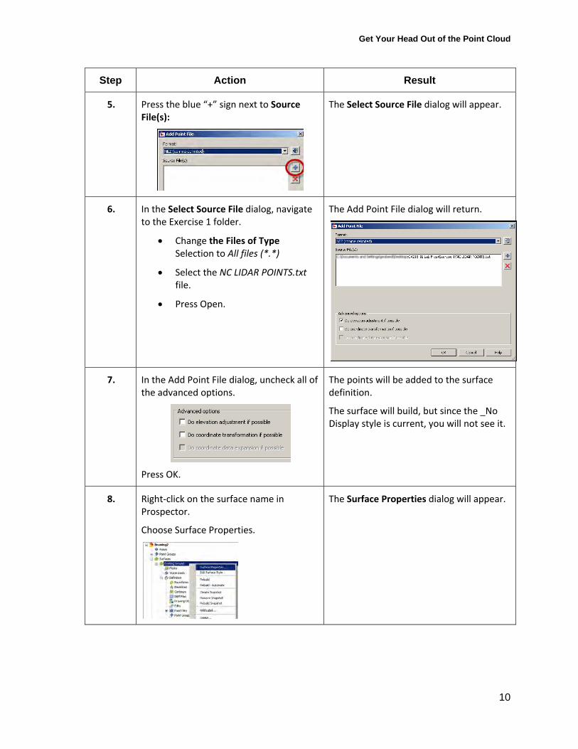
5. Press the blue “+” sign next to Source File(s):
The Select Source File dialog will appear.
6. In the Select Source File dialog, navigate to the Exercise 1 folder.
Change the Files of Type Selection to All files (*.*)
Select the NC LIDAR POINTS.txt file.
Press Open.
The Add Point File dialog will return.
7. In the Add Point File dialog, uncheck all of the advanced options.
Press OK.
The points will be added to the surface definition.
The surface will build, but since the _No Display style is current, you will not see it.
8. Right‐click on the surface name in Prospector.
Choose Surface Properties.
The Surface Properties dialog will appear.
Get Your Head Out of the Point Cloud
11
Step Action Result
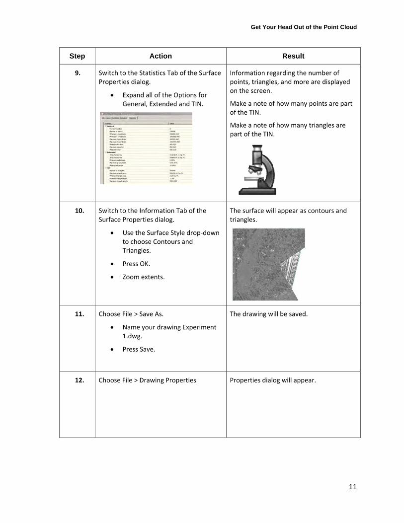
9. Switch to the Statistics Tab of the Surface Properties dialog.
Expand all of the Options for General, Extended and TIN.
Information regarding the number of points, triangles, and more are displayed on the screen.
Make a note of how many points are part of the TIN.
Make a note of how many triangles are part of the TIN.
10. Switch to the Information Tab of the Surface Properties dialog.
Use the Surface Style drop‐down to choose Contours and Triangles.
Press OK.
Zoom extents.
The surface will appear as contours and triangles.
11. Choose File > Save As.
Name your drawing Experiment 1.dwg.
Press Save.
The drawing will be saved.
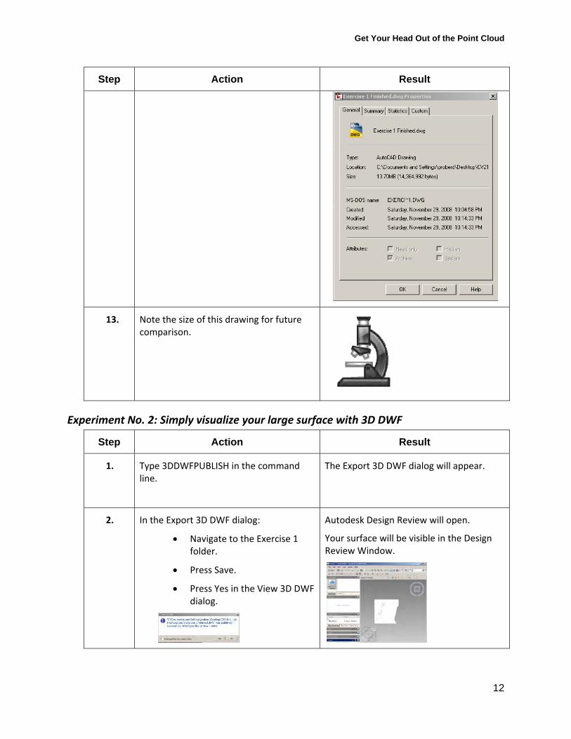
12. Choose File > Drawing Properties Properties dialog will appear.
Get Your Head Out of the Point Cloud
12
Step Action Result
13. Note the size of this drawing for future comparison.
Experiment No. 2: Simply visualize your large surface with 3D DWF
Step Action Result
1. Type 3DDWFPUBLISH in the command line.
The Export 3D DWF dialog will appear.
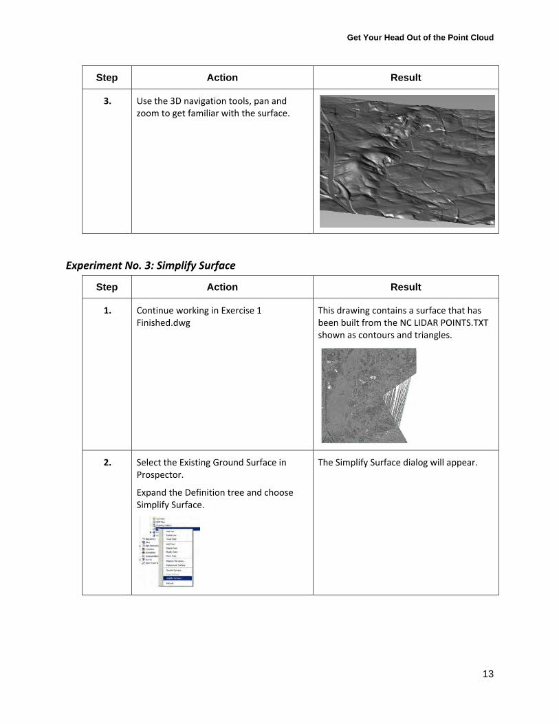
2. In the Export 3D DWF dialog:
Navigate to the Exercise 1 folder.
Press Save.
Press Yes in the View 3D DWF dialog.
Autodesk Design Review will open.
Your surface will be visible in the Design Review Window.
Get Your Head Out of the Point Cloud
13
Step Action Result
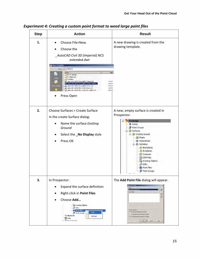
3. Use the 3D navigation tools, pan and zoom to get familiar with the surface.
Experiment No. 3: Simplify Surface
Step Action Result
1. Continue working in Exercise 1 Finished.dwg
This drawing contains a surface that has been built from the NC LIDAR POINTS.TXT shown as contours and triangles.
2. Select the Existing Ground Surface in Prospector.
Expand the Definition tree and choose Simplify Surface.
The Simplify Surface dialog will appear.

Get Your Head Out of the Point Cloud
14
Step Action Result
3. In the Simplify Surface dialog, select Point Removal then press Next.
You’ve selected point removal as the surface simplification method.
4. In the Region Options, choose Use Existing Surface Border. Press Next.
The method will use the existing limits of the surface, alternatively, you could specify a different area, such as a smaller area that didn’t need to have as much data.
5. In the Reduction Options, use the slider to choose 50%. Press Apply.
50% of the points will be removed from the surface.
6. Save the drawing as Experiment 3.dwg.
Note the number of triangles, number of points and drawing size in the laboratory worksheet.
Get Your Head Out of the Point Cloud
15
Experiment 4: Creating a custom point format to weed large point files
Step Action Result
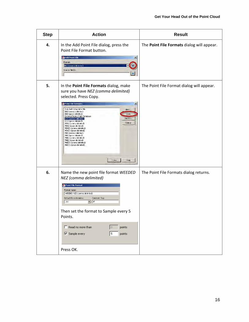
1. Choose File>New.
Choose the
_AutoCAD Civil 3D (Imperial) NCS extended.dwt
Press Open
A new drawing is created from the drawing template.
2. Choose Surfaces > Create Surface
In the create Surface dialog:
Name the surface Existing Ground
Select the _No Display style
Press OK
A new, empty surface is created in Prospector.
3. In Prospector:
Expand the surface definition
Right‐click in Point Files
Choose Add…
The Add Point File dialog will appear.
Get Your Head Out of the Point Cloud
16
Step Action Result
4. In the Add Point File dialog, press the Point File Format button.
The Point File Formats dialog will appear.
5. In the Point File Formats dialog, make sure you have NEZ (comma delimited) selected. Press Copy.
The Point File Format dialog will appear.
6. Name the new point file format WEEDED NEZ (comma delimited)
Then set the format to Sample every 5 Points.
Press OK.
The Point File Formats dialog returns.

Get Your Head Out of the Point Cloud
17
Step Action Result
7. Press Close. The Add Point File dialog returns.
8. Use the Format pull‐down to choose
WEEDED NEZ (comma delimited).
The newly created point file format will be used for importing a point file into the surface definition.
9. Press the blue “+” sign next to Source File(s):
The Select Source File dialog will appear.
10. In the Select Source File dialog, navigate to the Exercise 2 folder.
Change the Files of Type Selection to All files (*.*)
Select the NC LIDAR POINTS.txt file.
Press Open.
The Add Point File dialog will return.
11. In the Add Point File dialog, uncheck all of the advanced options.
Press OK.
The points will be added to the surface definition.
The surface will build, but since the _No Display style is current, you will not see it.
Get Your Head Out of the Point Cloud
18
Step Action Result
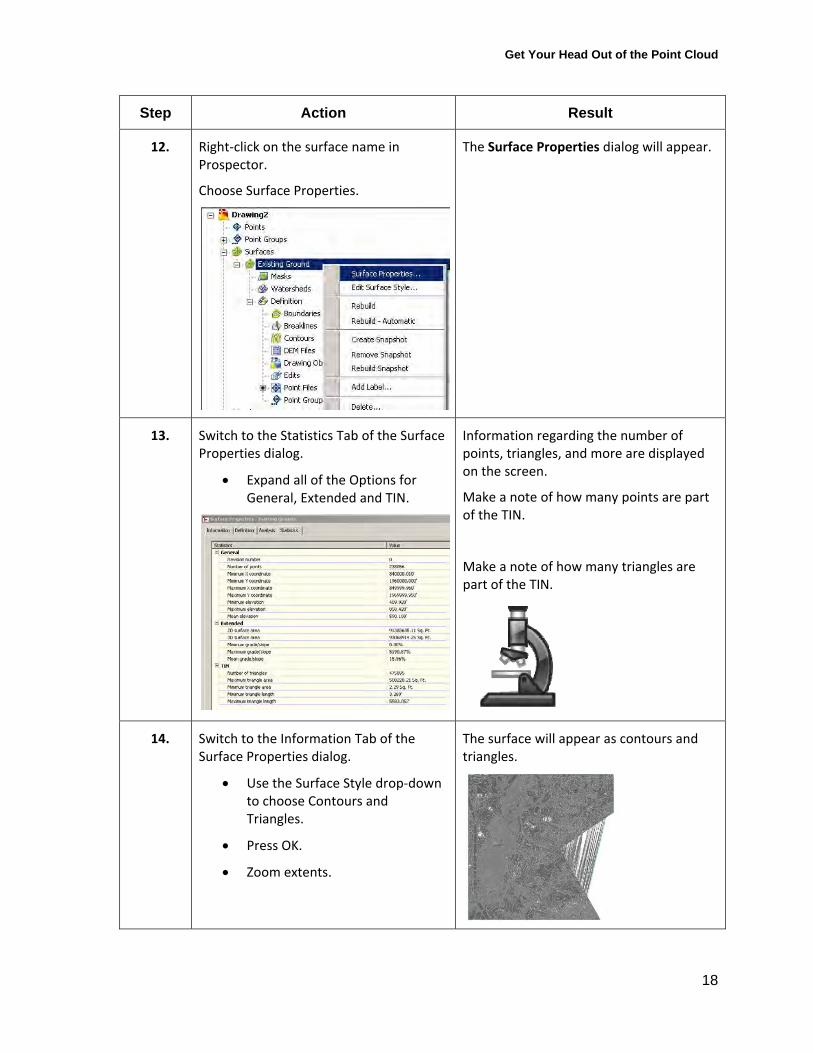
12. Right‐click on the surface name in Prospector.
Choose Surface Properties.
The Surface Properties dialog will appear.
13. Switch to the Statistics Tab of the Surface Properties dialog.
Expand all of the Options for General, Extended and TIN.
Information regarding the number of points, triangles, and more are displayed on the screen.
Make a note of how many points are part of the TIN.
Make a note of how many triangles are part of the TIN.
14. Switch to the Information Tab of the Surface Properties dialog.
Use the Surface Style drop‐down to choose Contours and Triangles.
Press OK.
Zoom extents.
The surface will appear as contours and triangles.

Get Your Head Out of the Point Cloud
19
Step Action Result
15. Choose File > Save As.
Navigate to the class folder.
Name your drawing Experiment 4. Finished.dwg.
Press Save.
The drawing will be saved.
16. Choose File > Drawing Properties Properties dialog will appear.
17. Note the size of this drawing for future comparison.
√ Points cannot be weeded by location using this method. For another approach to importing LIDAR point files, check out this article by Chris Gountanis of ImaginIT. Note that I have not confirmed if this method works in the 2009 version. http://imaginit.rand.com/files/Workin%20with%20Lidar%20Data-White_Paper.pdf
Get Your Head Out of the Point Cloud
20
Experiment 5: Using a Dataclip Boundary
Step Action Result
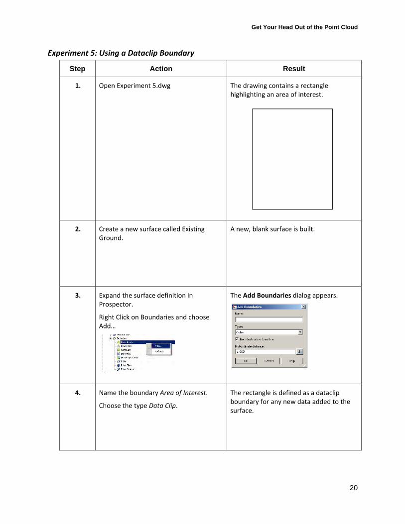
1. Open Experiment 5.dwg The drawing contains a rectangle highlighting an area of interest.
2. Create a new surface called Existing Ground.
A new, blank surface is built.
3. Expand the surface definition in Prospector.
Right Click on Boundaries and choose Add…
The Add Boundaries dialog appears.
4. Name the boundary Area of Interest.
Choose the type Data Clip.
The rectangle is defined as a dataclip boundary for any new data added to the surface.
Get Your Head Out of the Point Cloud
21
Step Action Result
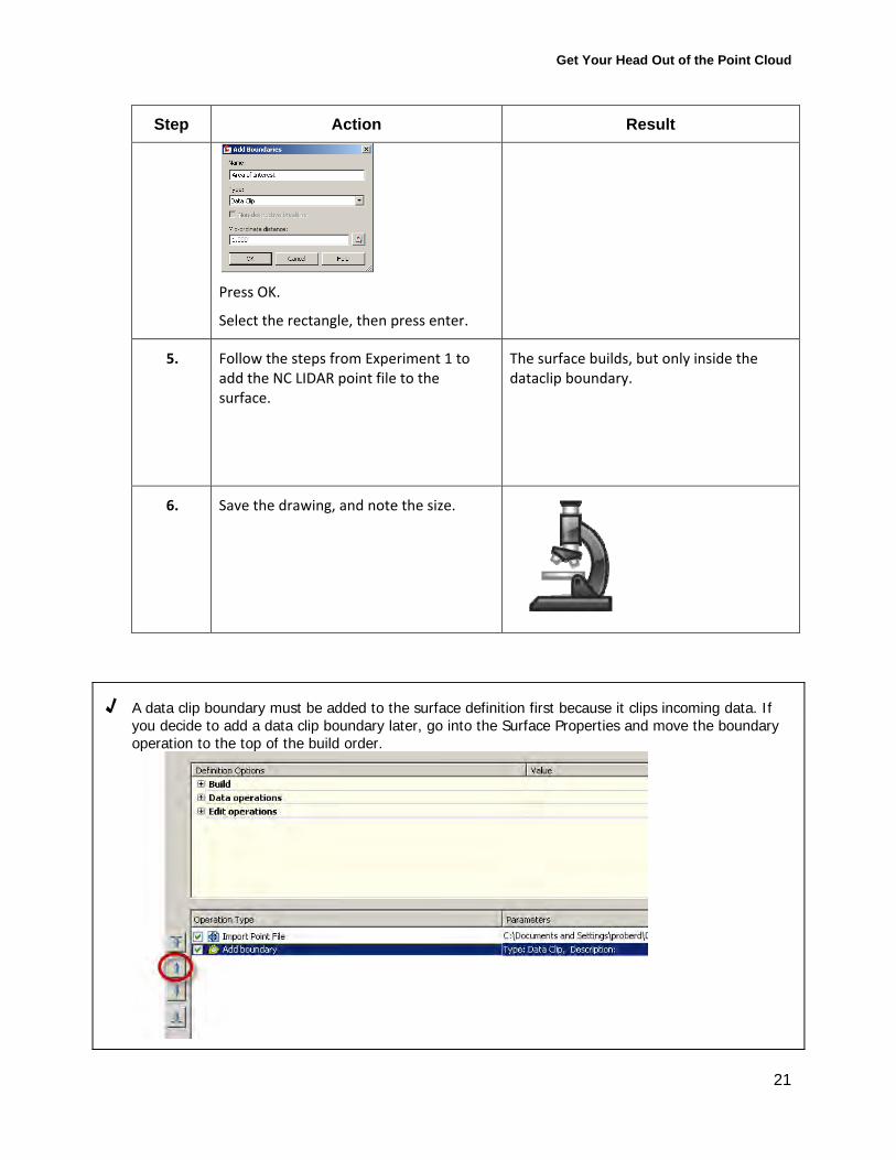
Press OK.
Select the rectangle, then press enter.
5. Follow the steps from Experiment 1 to add the NC LIDAR point file to the surface.
The surface builds, but only inside the dataclip boundary.
6. Save the drawing, and note the size.
√ A data clip boundary must be added to the surface definition first because it clips incoming data. If you decide to add a data clip boundary later, go into the Surface Properties and move the boundary operation to the top of the build order.
Get Your Head Out of the Point Cloud
22
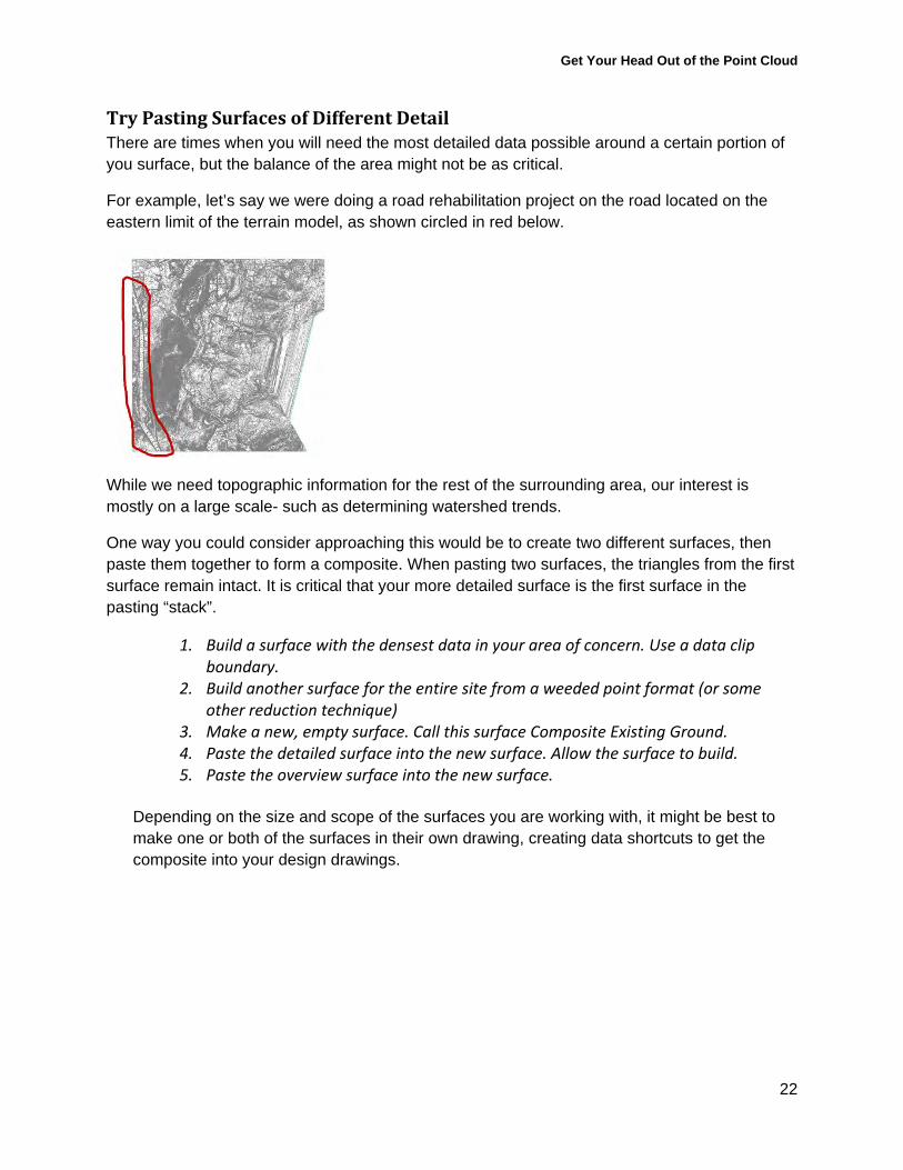
Try Pasting Surfaces of Different Detail There are times when you will need the most detailed data possible around a certain portion of you surface, but the balance of the area might not be as critical.
For example, let’s say we were doing a road rehabilitation project on the road located on the eastern limit of the terrain model, as shown circled in red below.
While we need topographic information for the rest of the surrounding area, our interest is mostly on a large scale- such as determining watershed trends.
One way you could consider approaching this would be to create two different surfaces, then paste them together to form a composite. When pasting two surfaces, the triangles from the first surface remain intact. It is critical that your more detailed surface is the first surface in the pasting “stack”.
1. Build a surface with the densest data in your area of concern. Use a data clip boundary.
2. Build another surface for the entire site from a weeded point format (or some other reduction technique)
3. Make a new, empty surface. Call this surface Composite Existing Ground. 4. Paste the detailed surface into the new surface. Allow the surface to build. 5. Paste the overview surface into the new surface.
Depending on the size and scope of the surfaces you are working with, it might be best to make one or both of the surfaces in their own drawing, creating data shortcuts to get the composite into your design drawings.

Get Your Head Out of the Point Cloud
23
Building Surfaces from LIDAR or other Aerial Contours LIDAR contours are often publically available.
An example of LIDAR contours. Contours are probably the least desirable type of data for surface creation. By definition, contours are the end product of a terrain model, not the raw materials. However, there are some times where the only data you have is contour data. When contours are your only option, follow the procedure below to create a surface.
Experiment 6: Using a Map Query to pull in a portion of the contour data
Step Action Result
1. Choose File>Open.
Navigate to the Experiment 6 Contours.dwg
Press Open
A drawing is opened that contains contours from aerial LiDAR.
The contours are polylines drawn at 5ft intervals.
2. Zoom in on one of the “contours”.
Select the Contour.
The vertices for the contour will light up. Notice how close they are.
Get Your Head Out of the Point Cloud
24
Step Action Result
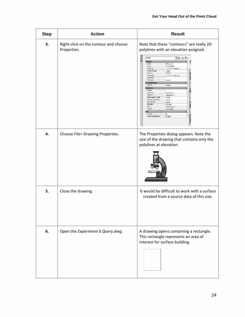
3. Right‐click on the contour and choose Properties.
Note that these “contours” are really 2D polylines with an elevation assigned.
4. Choose File> Drawing Properties. The Properties dialog appears. Note the size of the drawing that contains only the polylines at elevation.
5. Close the drawing It would be difficult to work with a surface created from a source data of this size.
6. Open the Experiment 6 Query.dwg. A drawing opens containing a rectangle. This rectangle represents an area of interest for surface building.
Get Your Head Out of the Point Cloud
25
Step Action Result
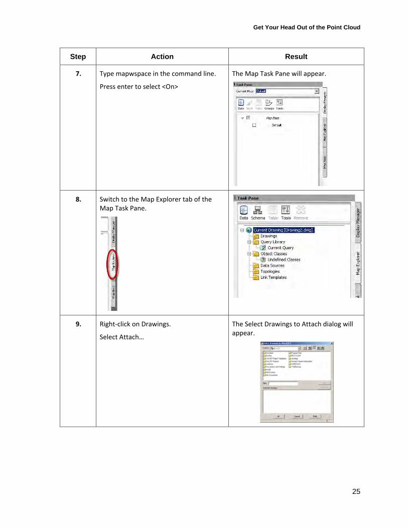
7. Type mapwspace in the command line.
Press enter to select <On>
The Map Task Pane will appear.
8.
Switch to the Map Explorer tab of the Map Task Pane.
9. Right‐click on Drawings.
Select Attach…
The Select Drawings to Attach dialog will appear.
Get Your Head Out of the Point Cloud
26
Step Action Result
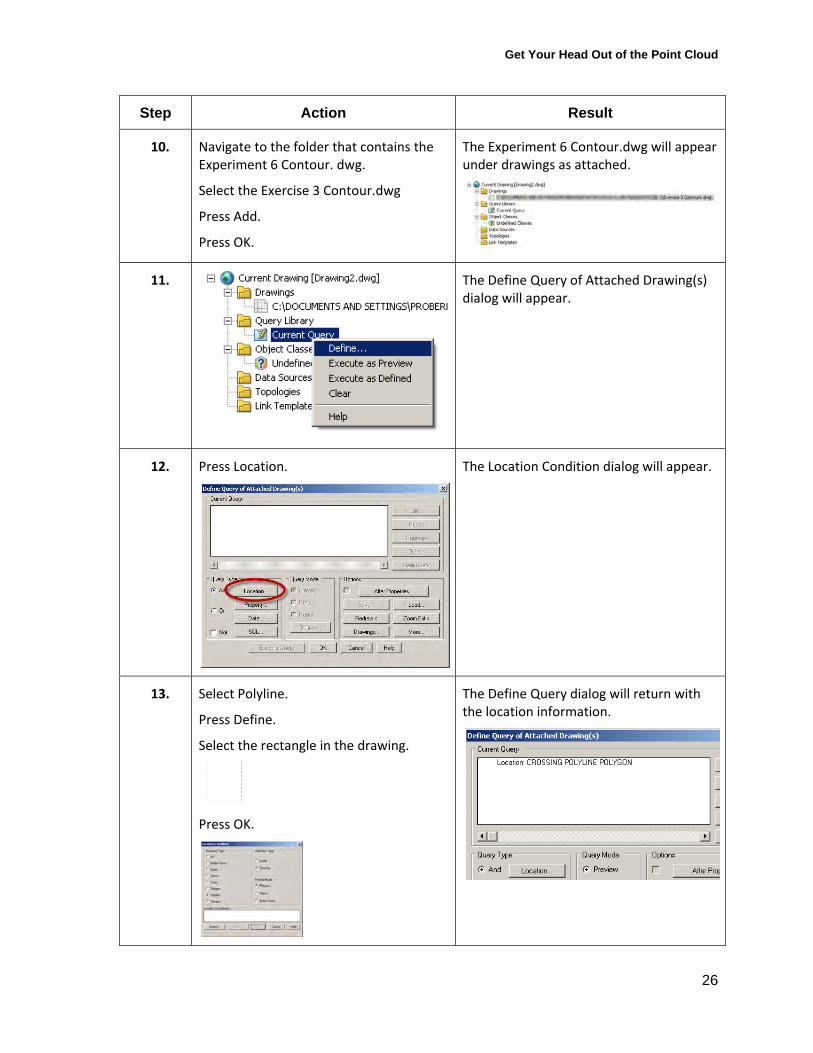
10. Navigate to the folder that contains the Experiment 6 Contour. dwg.
Select the Exercise 3 Contour.dwg
Press Add.
Press OK.
The Experiment 6 Contour.dwg will appear under drawings as attached.
11. The Define Query of Attached Drawing(s) dialog will appear.
12. Press Location. The Location Condition dialog will appear.
13. Select Polyline.
Press Define.
Select the rectangle in the drawing.
Press OK.
The Define Query dialog will return with the location information.
Get Your Head Out of the Point Cloud
27
Step Action Result
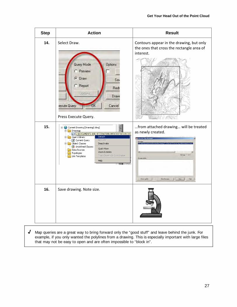
14. Select Draw.
Press Execute Query.
Contours appear in the drawing, but only the ones that cross the rectangle area of interest.
15. …from attached drawing… will be treated as newly created.
16. Save drawing. Note size.
√ Map queries are a great way to bring forward only the “good stuff” and leave behind the junk. For example, if you only wanted the polylines from a drawing. This is especially important with large files that may not be easy to open and are often impossible to “block in”.
Get Your Head Out of the Point Cloud
28
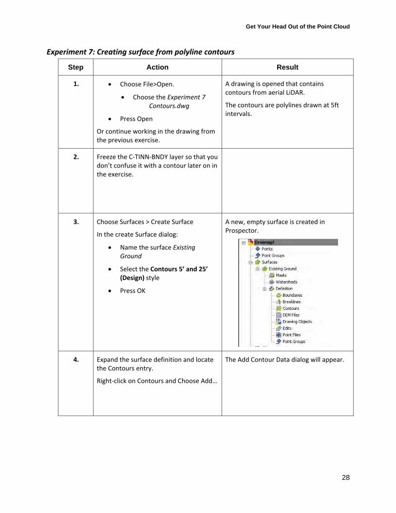
Experiment 7: Creating surface from polyline contours
Step Action Result
1. Choose File>Open.
Choose the Experiment 7 Contours.dwg
Press Open
Or continue working in the drawing from the previous exercise.
A drawing is opened that contains contours from aerial LiDAR.
The contours are polylines drawn at 5ft intervals.
2. Freeze the C‐TINN‐BNDY layer so that you don’t confuse it with a contour later on in the exercise.
3. Choose Surfaces > Create Surface
In the create Surface dialog:
Name the surface Existing Ground
Select the Contours 5’ and 25’ (Design) style
Press OK
A new, empty surface is created in Prospector.
4. Expand the surface definition and locate the Contours entry.
Right‐click on Contours and Choose Add…
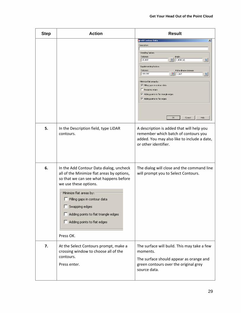
The Add Contour Data dialog will appear.
Get Your Head Out of the Point Cloud
29
Step Action Result
5. In the Description field, type LiDAR contours.
A description is added that will help you remember which batch of contours you added. You may also like to include a date, or other identifier.
6. In the Add Contour Data dialog, uncheck all of the Minimize flat areas by options, so that we can see what happens before we use these options.
Press OK.
The dialog will close and the command line will prompt you to Select Contours.
7. At the Select Contours prompt, make a crossing window to choose all of the contours.
Press enter.
The surface will build. This may take a few moments.
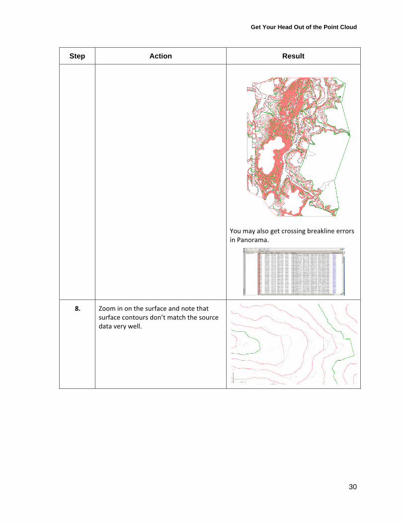
The surface should appear as orange and green contours over the original grey source data.
Get Your Head Out of the Point Cloud
30
Step Action Result
You may also get crossing breakline errors in Panorama.
8. Zoom in on the surface and note that surface contours don’t match the source data very well.
Get Your Head Out of the Point Cloud
31
Step Action Result
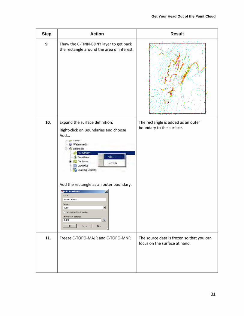
9. Thaw the C‐TINN‐BDNY layer to get back the rectangle around the area of interest.
10. Expand the surface definition.
Right‐click on Boundaries and choose Add...
Add the rectangle as an outer boundary.
The rectangle is added as an outer boundary to the surface.
11. Freeze C‐TOPO‐MAJR and C‐TOPO‐MNR The source data is frozen so that you can focus on the surface at hand.
Get Your Head Out of the Point Cloud
32
Step Action Result
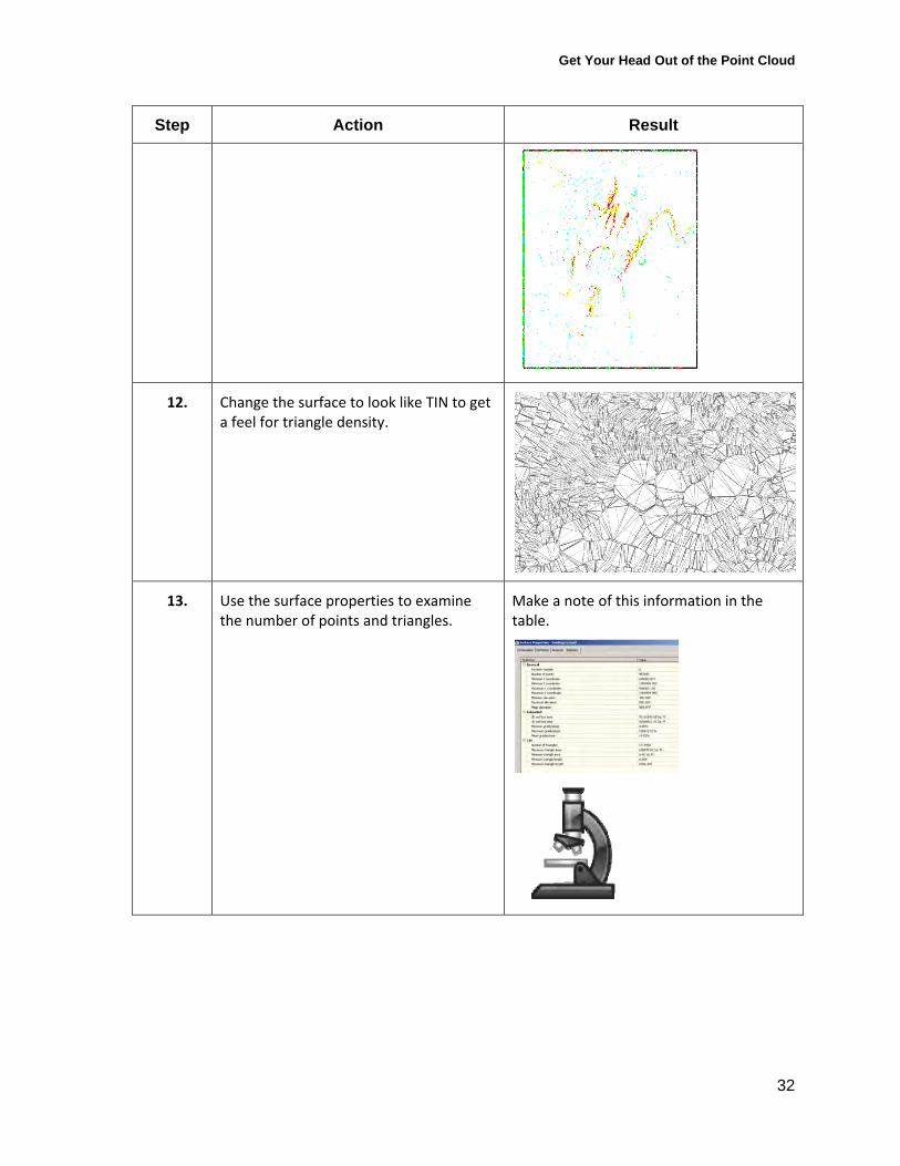
12.
Change the surface to look like TIN to get a feel for triangle density.
13. Use the surface properties to examine the number of points and triangles.
Make a note of this information in the table.
Get Your Head Out of the Point Cloud
33
Step Action Result
14. Save the drawing. Make a note of the drawing size.
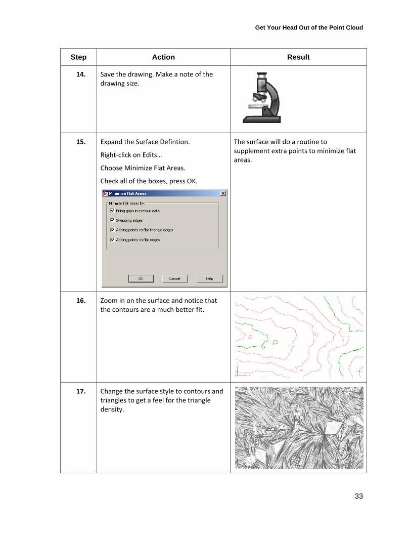
15. Expand the Surface Defintion.
Right‐click on Edits…
Choose Minimize Flat Areas.
Check all of the boxes, press OK.
The surface will do a routine to supplement extra points to minimize flat areas.
16. Zoom in on the surface and notice that the contours are a much better fit.
17. Change the surface style to contours and triangles to get a feel for the triangle density.

Get Your Head Out of the Point Cloud
34
Step Action Result
18. Save the drawing, make a note of the points, triangles and drawing size.
Depending on your project needs, you may be able to greatly reduce the size of your surface and your drawing without sacrificing accuracy. LIDAR contours are often present as polylines with many closely spaced vertices. These closely spaced vertices often do not provide any additional meaningful data and can be weeded resulting in a more manageable surface. Investigate Map Cleanup tools to simplify polyline contours before using them for surface creation.
Get Your Head Out of the Point Cloud
35
Building Surfaces from Aerial Topographic Data Many firms will have a site “flown” by an aerial topography company in lieu of sending a crew out in the field. Typically, the aerial company will provide you with two .dwgs. The first contains features and the second contains DTM data.
When hiring an aerial topography company, be sure to ask what formats are available for the final data. Many firms are capable of providing data formats such as LandXML, DEM or a .TIN file that might be more useful to you than the traditional .dwg information.
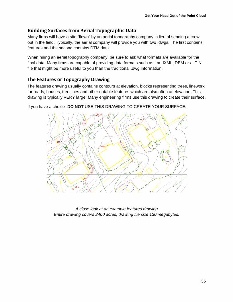
The Features or Topography Drawing The features drawing usually contains contours at elevation, blocks representing trees, linework for roads, houses, tree lines and other notable features which are also often at elevation. This drawing is typically VERY large. Many engineering firms use this drawing to create their surface.
If you have a choice- DO NOT USE THIS DRAWING TO CREATE YOUR SURFACE.
A close look at an example features drawing Entire drawing covers 2400 acres, drawing file size 130 megabytes.
Get Your Head Out of the Point Cloud
36
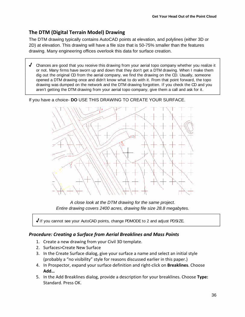
The DTM (Digital Terrain Model) Drawing The DTM drawing typically contains AutoCAD points at elevation, and polylines (either 3D or 2D) at elevation. This drawing will have a file size that is 50-75% smaller than the features drawing. Many engineering offices overlook this data for surface creation.
√ Chances are good that you receive this drawing from your aerial topo company whether you realize it or not. Many firms have sworn up and down that they don’t get a DTM drawing. When I make them dig out the original CD from the aerial company, we find the drawing on the CD. Usually, someone opened a DTM drawing once and didn’t know what to do with it. From that point forward, the topo drawing was dumped on the network and the DTM drawing forgotten. If you check the CD and you aren’t getting the DTM drawing from your aerial topo company, give them a call and ask for it.
If you have a choice- DO USE THIS DRAWING TO CREATE YOUR SURFACE.
A close look at the DTM drawing for the same project. Entire drawing covers 2400 acres, drawing file size 28.8 megabytes.
√ If you cannot see your AutoCAD points, change PDMODE to 2 and adjust PDSIZE.
Procedure: Creating a Surface from Aerial Breaklines and Mass Points
1. Create a new drawing from your Civil 3D template. 2. Surfaces>Create New Surface 3. In the Create Surface dialog, give your surface a name and select an initial style
(probably a “no visibility” style for reasons discussed earlier in this paper.) 4. In Prospector, expand your surface definition and right‐click on Breaklines. Choose
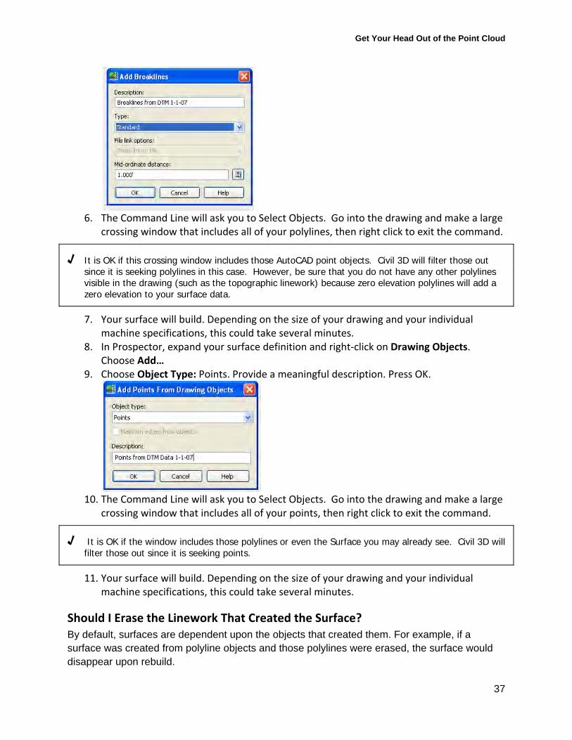
Add… 5. In the Add Breaklines dialog, provide a description for your breaklines. Choose Type:
Standard. Press OK.
Get Your Head Out of the Point Cloud
37
6. The Command Line will ask you to Select Objects. Go into the drawing and make a large
crossing window that includes all of your polylines, then right click to exit the command.
√ It is OK if this crossing window includes those AutoCAD point objects. Civil 3D will filter those out since it is seeking polylines in this case. However, be sure that you do not have any other polylines visible in the drawing (such as the topographic linework) because zero elevation polylines will add a zero elevation to your surface data.
7. Your surface will build. Depending on the size of your drawing and your individual machine specifications, this could take several minutes.
8. In Prospector, expand your surface definition and right‐click on Drawing Objects. Choose Add…
9. Choose Object Type: Points. Provide a meaningful description. Press OK.
10. The Command Line will ask you to Select Objects. Go into the drawing and make a large
crossing window that includes all of your points, then right click to exit the command.
√ It is OK if the window includes those polylines or even the Surface you may already see. Civil 3D will filter those out since it is seeking points.
11. Your surface will build. Depending on the size of your drawing and your individual machine specifications, this could take several minutes.
Should I Erase the Linework That Created the Surface? By default, surfaces are dependent upon the objects that created them. For example, if a surface was created from polyline objects and those polylines were erased, the surface would disappear upon rebuild.
Get Your Head Out of the Point Cloud
38
You can change this setting using the following procedure:
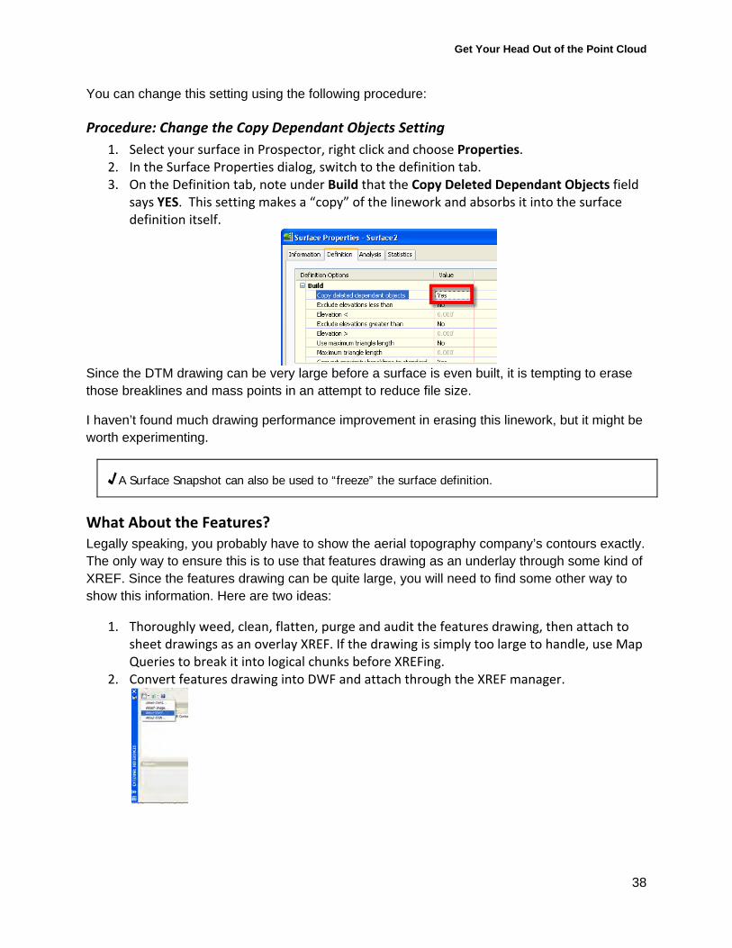
Procedure: Change the Copy Dependant Objects Setting
1. Select your surface in Prospector, right click and choose Properties. 2. In the Surface Properties dialog, switch to the definition tab. 3. On the Definition tab, note under Build that the Copy Deleted Dependant Objects field
says YES. This setting makes a “copy” of the linework and absorbs it into the surface definition itself.
Since the DTM drawing can be very large before a surface is even built, it is tempting to erase those breaklines and mass points in an attempt to reduce file size.
I haven’t found much drawing performance improvement in erasing this linework, but it might be worth experimenting.
√ A Surface Snapshot can also be used to “freeze” the surface definition.
What About the Features? Legally speaking, you probably have to show the aerial topography company’s contours exactly. The only way to ensure this is to use that features drawing as an underlay through some kind of XREF. Since the features drawing can be quite large, you will need to find some other way to show this information. Here are two ideas:
1. Thoroughly weed, clean, flatten, purge and audit the features drawing, then attach to sheet drawings as an overlay XREF. If the drawing is simply too large to handle, use Map Queries to break it into logical chunks before XREFing.
2. Convert features drawing into DWF and attach through the XREF manager.

Get Your Head Out of the Point Cloud
39
Ideas for Drawing and Data Organization Your drawings should be organized to take advantage of the strengths of the software.
1. Only keep surfaces you need in a drawing. 2. Keep individual surfaces to less than a million points where possible. 3. Label only where necessary. 4. Stylize only where necessary. 5. Avoid XREFing drawings containing surfaces, especially styled or labeled surfaces. 6. Use data references and style application instead of XREF and layer control to share
surface information between drawings.
√ Civil 3D labels are regenerated every time you change views or switch layout tabs. This includes when the labels are XREF’ed into another drawing. The biggest performance problems I have encountered in Civil 3D 2008 are related to label regeneration.
Keeping the previous three items in mind, you might consider having three types of drawings: Warehouse Drawings, Surface Only Drawings and Design Drawings.
Warehouse Drawings The Warehouse drawing will keep the original data or linework for the entire site, such as the data from the LIDAR contours or aerial topography drawing. Keep this data in a safe place, and consider making it read only. Later in the paper we will talk about weeding data. You might want to make a “weeded” warehouse drawing at some point.
Drawing template: Make a plain template with no styles.
In your warehouse drawing, you might decide where logical breaks would be for smaller surface creation, perhaps marking with rectangles.
√ Investigate the Map Books tool in AutoCAD Map and/or the Plan Production tool in Civil 3D to possibly assist in semi-automatic sheet creation based on your phases.
Surface Only Drawings Surface Only drawings will house individual “tile” surfaces. Using Map Tools, raw data is queried for the appropriate location. After checking your TIN, apply a no-visibility style to your surface and avoid labeling. You can leave the attachment for future queries or break the connection. Experiment with erasing the AutoCAD entities, snapshots and build operations to find a drawing size that works best. Consider querying small chunks for use in detailed phase design, and larger chunks that are then weeded for a bigger surface that is a lower resolution.
Drawing template: Make a simple template that includes no object styles except a no-visibility surface style and a triangle only style.
Get Your Head Out of the Point Cloud
40
Design Drawings Data Reference (through data shortcuts or Vault) only the surfaces that are necessary in that drawing for design, daylighting, profile work, etc. Label only as necessary. Maintain as few layouts with as few viewports as possible and use data references and styles to control visibility rather than xrefs and layer control. Avoid xrefing drawings with surfaces, or any other civil 3d objects that are heavily labeled.
Drawing template: Use your company standard design template.
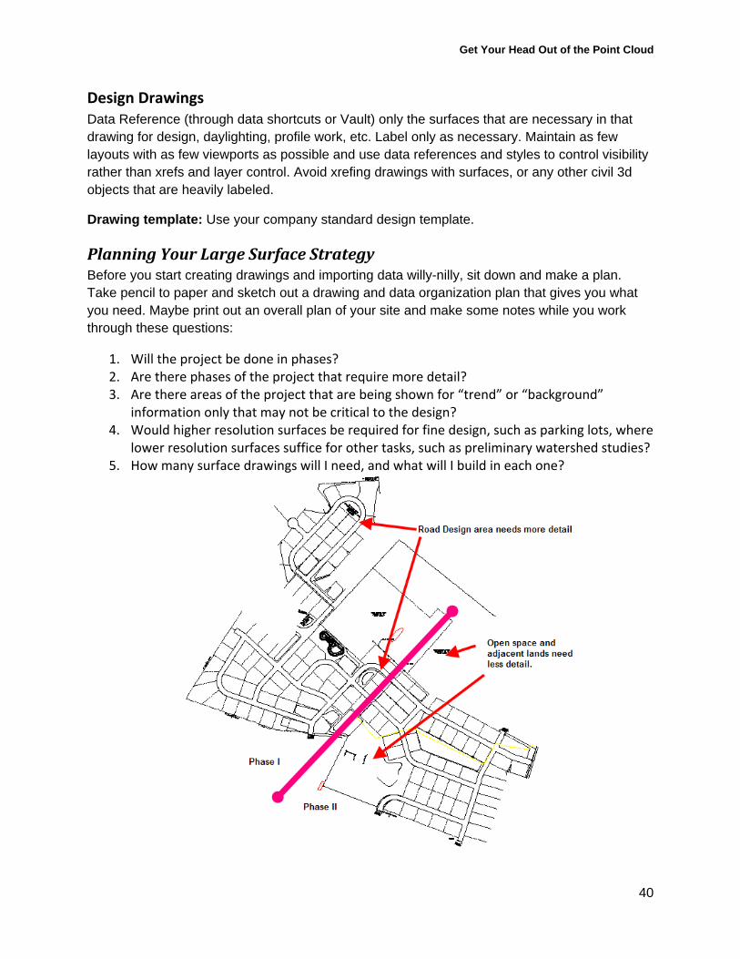
Planning Your Large Surface Strategy Before you start creating drawings and importing data willy-nilly, sit down and make a plan. Take pencil to paper and sketch out a drawing and data organization plan that gives you what you need. Maybe print out an overall plan of your site and make some notes while you work through these questions:
1. Will the project be done in phases? 2. Are there phases of the project that require more detail? 3. Are there areas of the project that are being shown for “trend” or “background”
information only that may not be critical to the design? 4. Would higher resolution surfaces be required for fine design, such as parking lots, where
lower resolution surfaces suffice for other tasks, such as preliminary watershed studies? 5. How many surface drawings will I need, and what will I build in each one?
Get Your Head Out of the Point Cloud
41
A Large Drawing Is NOT a Badge Of Honor Before you even consider building a surface in your drawing, take a look around and make sure your drawing is big for good reason.
Common Culprits:
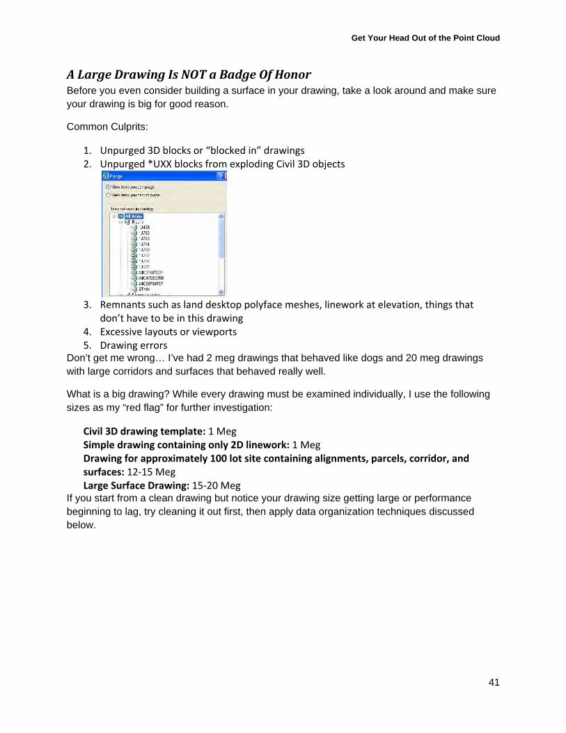
1. Unpurged 3D blocks or “blocked in” drawings 2. Unpurged *UXX blocks from exploding Civil 3D objects
3. Remnants such as land desktop polyface meshes, linework at elevation, things that
don’t have to be in this drawing 4. Excessive layouts or viewports 5. Drawing errors
Don’t get me wrong… I’ve had 2 meg drawings that behaved like dogs and 20 meg drawings with large corridors and surfaces that behaved really well.
What is a big drawing? While every drawing must be examined individually, I use the following sizes as my “red flag” for further investigation:
Civil 3D drawing template: 1 Meg Simple drawing containing only 2D linework: 1 Meg Drawing for approximately 100 lot site containing alignments, parcels, corridor, and surfaces: 12‐15 Meg Large Surface Drawing: 15‐20 Meg
If you start from a clean drawing but notice your drawing size getting large or performance beginning to lag, try cleaning it out first, then apply data organization techniques discussed below.

Get Your Head Out of the Point Cloud
42
Techniques To Practice For Large Surface Data Preparation Don’t Use.. Instead Learn...
Import Points Adding Points directly to surface; applying weeding to point files
Object Viewer View>3D Views; 3DDWFPUBISH
Converting AutoCAD Points to Civil 3D Points
Add AutoCAD Points directly to surface
QSELECT, Select Similar, other selection tools
Map Query for location and property
Insert another drawing as a block, or copyclip
Map Query
Map Trim, EXTRIM Map Query for location
Flatten, or properties change Map Query with Alter Properties
Adding every bit of data just because it is there
Choosing the important and meaningful data

Get Your Head Out of the Point Cloud
43
Resources
Books American Society of Civil Engineers. Topographic Surveying. 2000.
Robert C. Steele. Modern Topographic Drawing. 1980.
Online Materials Best Practices for Working with Large Data Sets White Paper from Autodesk http://images.autodesk.com/adsk/files/large_data_best_practice.pdf
Working with LIDAR data in Civil 3D from Chris Gountanis of Imaginit
http://imaginit.rand.com/files/Workin%20with%20Lidar%20Data-White_Paper.pdf
Manage Surfaces by Mike Choquette of Imaginit
http://aec.cadalyst.com/aec/Column:+CAD+Clinic/Manage-Surfaces-Part-1-CAD-Clinic-Civil-3D-Tutoria/ArticleStandard/Article/detail/470059
Blog Resources for Using Map Tools and Dealing with Large Surfaces: www.civil3d.com
Map 3D and Murph’s Law at http://map3d.wordpress.com/
Take the Edge off Civil 3D at http://edgeofwedge.com/civil.php
Get Your Head Out of the Point Cloud
44
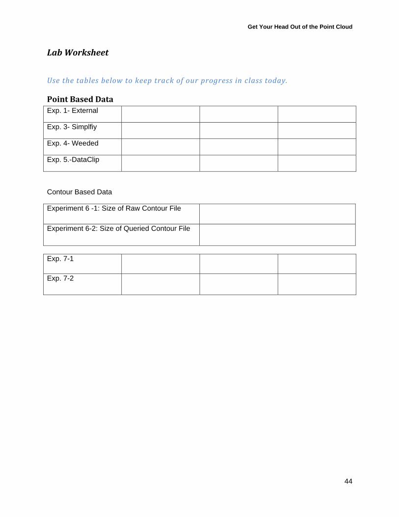
Lab Worksheet
Use the tables below to keep track of our progress in class today.
Point Based Data Exp. 1- External
Exp. 3- Simplfiy
Exp. 4- Weeded
Exp. 5.-DataClip
Contour Based Data
Experiment 6 -1: Size of Raw Contour File
Experiment 6-2: Size of Queried Contour File
Exp. 7-1
Exp. 7-2
Get Your Head Out of the Point Cloud
45
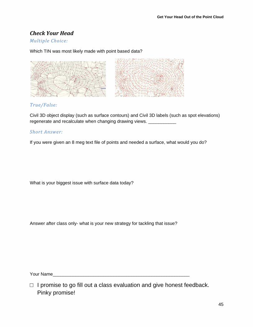
Check Your Head Multiple Choice:
Which TIN was most likely made with point based data?
True/False:
Civil 3D object display (such as surface contours) and Civil 3D labels (such as spot elevations) regenerate and recalculate when changing drawing views. ___________
Short Answer:
If you were given an 8 meg text file of points and needed a surface, what would you do?
What is your biggest issue with surface data today?
Answer after class only- what is your new strategy for tackling that issue?
Your Name______________________________________________________
□ I promise to go fill out a class evaluation and give honest feedback. Pinky promise!


![Curso de Autodesk Autocad® - Cursos de Diseño Gráfico ...Curso de Autodesk Autocad® 2D 30 HRS Autodesk Autocad® 2D Autodesk Autocad® [ Diseño y documentación de planos ] 30](https://img.pdfslide.net/doc/110x75/60bf32457f62ce72bb78f8cb/curso-de-autodesk-autocad-cursos-de-diseo-grfico-curso-de-autodesk-autocad.jpg)