Embed Size (px)
Citation preview
LAB MANUAL/ECM
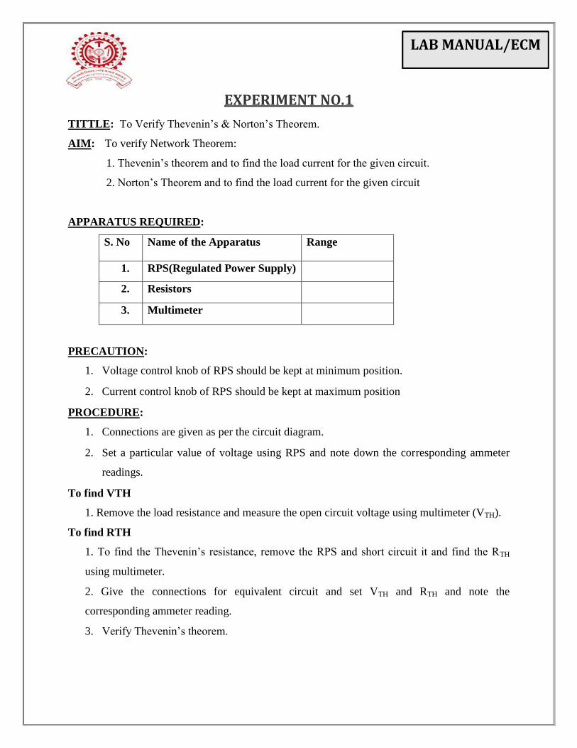
EXPERIMENT NO.1
TITTLE: To Verify Thevenin’s & Norton’s Theorem.
AIM: To verify Network Theorem:
1. Thevenin’s theorem and to find the load current for the given circuit.
2. Norton’s Theorem and to find the load current for the given circuit
APPARATUS REQUIRED:
S. No Name of the Apparatus Range
1. RPS(Regulated Power Supply)
2. Resistors
3. Multimeter
PRECAUTION:
1. Voltage control knob of RPS should be kept at minimum position.
2. Current control knob of RPS should be kept at maximum position
PROCEDURE:
1. Connections are given as per the circuit diagram.
2. Set a particular value of voltage using RPS and note down the corresponding ammeter
readings.
To find VTH
1. Remove the load resistance and measure the open circuit voltage using multimeter (VTH).
To find RTH
1. To find the Thevenin’s resistance, remove the RPS and short circuit it and find the RTH
using multimeter.
2. Give the connections for equivalent circuit and set VTH and RTH and note the
corresponding ammeter reading.
3. Verify Thevenin’s theorem.
LAB MANUAL/ECM
CIRCUIT:
To find VTH
To find RTH
LAB MANUAL/ECM
Thevenin Equivalent Circuit
MODEL CALCULATIONS:

LAB MANUAL/ECM
OBSERVATION TABLE:
RTH VTH IL
Theoretical
Practical
CONCLUSION:
LAB MANUAL/ECM
FOR NOTRTONS THEOREM
PRECAUTION:
1. Voltage control knob of RPS should be kept at minimum position.
2. Current control knob of RPS should be kept at maximum position
PROCEDURE:
1. Connections are given as per the circuit diagram.
2. Set a particular value of voltage using RPS and note down the corresponding ammeter
readings.
To find IN
3. Remove the load resistance short circuit voltage the terminals.
4. For the same RPS voltage note down the ammeter readings.
To find RN
5. Remove the RPS and short circuit the terminal and remove the load and note down the
resistance across the two terminals.
Equivalent Circuit:
6. Set IN and RN and note down the ammeter readings.
7. Verify Norton’s Theorem.
To find load current in circuit I:
LAB MANUAL/ECM
To find ISC
To find RTH
Norton Equivalent Circuit
LAB MANUAL/ECM
MODEL CALCULATIONS:
OBSERVATION TABLE:
RTH ISC IL
Theoretical
Practical
CONCLUSION:
LAB MANUAL/ECM
TITLE: To determine the polarity of single phase transformer
AIM: To perform Polarity test in order to identify the like and unlike terminal.
APPARATUS:
Sr.
NO.
Instruments Range/Specification
1. Voltmeters
2. Dimmerstat
3. Transformer
PRECAUTIONS:
1. Be careful for the selection of the LV & HV coil of the transformer.
2. Ensure 0 V position of dimmer before turning the AC supply.
3. Ensure all the connection with care before start of experiment.
4. Do not exceed the input voltage beyond 220 V for HV coil.
5. Do not keep the circuit ON for long time.
6. Do not allow students without shoes.
THEORY:
Principle of Operation:
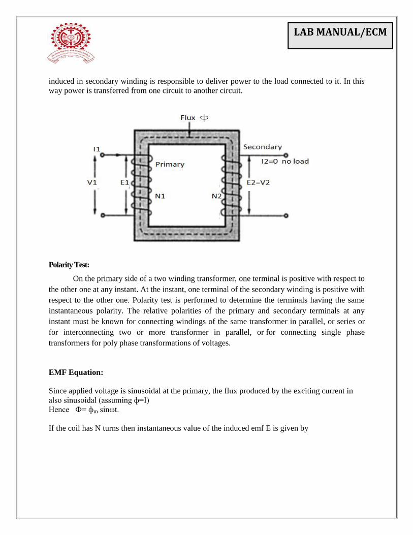
A Transformer works on the principle of electromagnetic induction between two or more
coupled circuit. When alternating voltage V1 applied to primary winding of transformer, a
current I1 flows through it, the exciting current produces an alternating flux in the core which
links both winding. According to faradays law of electromagnetic induction, The flux will causes
self-induced emf E1 in primary coil and mutually induced emf E2 in secondary winding. But
according to lenz’s law emf induced is equal and opposite to the applied voltage.When load is
connected to the secondary side, current will start flowing in the secondary winding. Voltage
EXPERIMENT NO.2
LAB MANUAL/ECM
induced in secondary winding is responsible to deliver power to the load connected to it. In this
way power is transferred from one circuit to another circuit.
Polarity Test:
On the primary side of a two winding transformer, one terminal is positive with respect to
the other one at any instant. At the instant, one terminal of the secondary winding is positive with
respect to the other one. Polarity test is performed to determine the terminals having the same
instantaneous polarity. The relative polarities of the primary and secondary terminals at any
instant must be known for connecting windings of the same transformer in parallel, or series or
for interconnecting two or more transformer in parallel, or for connecting single phase
transformers for poly phase transformations of voltages.
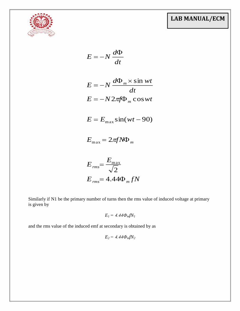
EMF Equation:
Since applied voltage is sinusoidal at the primary, the flux produced by the exciting current in
also sinusoidal (assuming ф=I)
Hence Ф= фm sinωt.
If the coil has N turns then instantaneous value of the induced emf E is given by
LAB MANUAL/ECM
Similarly if N1 be the primary number of turns then the rms value of induced voltage at primary
is given by
E1 = 4.44ФmfN1
and the rms value of the induced emf at secondary is obtained by as
E2 = 4.44ФmfN2
fNE
EE
fNE
wtEE
wtfNE
dt
wtdNE
dt
dNE
mrms
rms
m
m
m
44.4
2
2
)90sin(
cos2
sin
max
max
max
LAB MANUAL/ECM
PROCEDURES:
(A) Polarity Test (HV Coil on Supply Side)
1. Connect the circuit as per circuit diagram shown.
2. Select the proper ranges of the meters.
3. Ensure 0 Volt for dimmer stat with anticlockwise lock of rotor before turn on.
4. Increase the dimmer voltage slowly from 0 to 220V only (Rated Voltage).
5. Record the reading of all the volt meters.
(B) Turns Ratio Test (HV Coil on Supply Side)
1. Connect the circuit as per circuit diagram shown.
2. Select the proper ranges of the meters.
3. Ensure 0 Volt for dimmer stat with anticlockwise lock of rotor before turn on.
4. Increase the dimmer voltage slowly from 0 to 220V only (Rated Voltage).
5. Record the reading of all the volt meters.
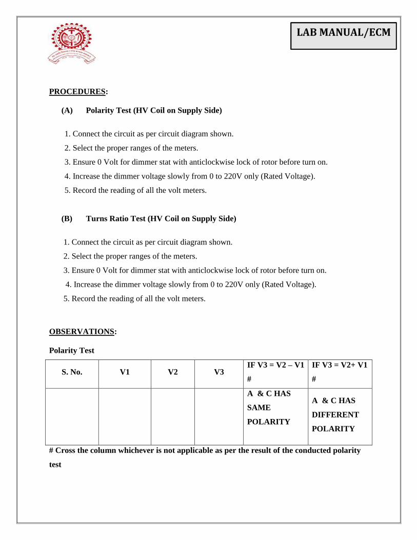
OBSERVATIONS:
Polarity Test
S. No. V1 V2 V3 IF V3 = V2 – V1
#
IF V3 = V2+ V1
#
A & C HAS
SAME
POLARITY
A & C HAS
DIFFERENT
POLARITY
# Cross the column whichever is not applicable as per the result of the conducted polarity
test
LAB MANUAL/ECM
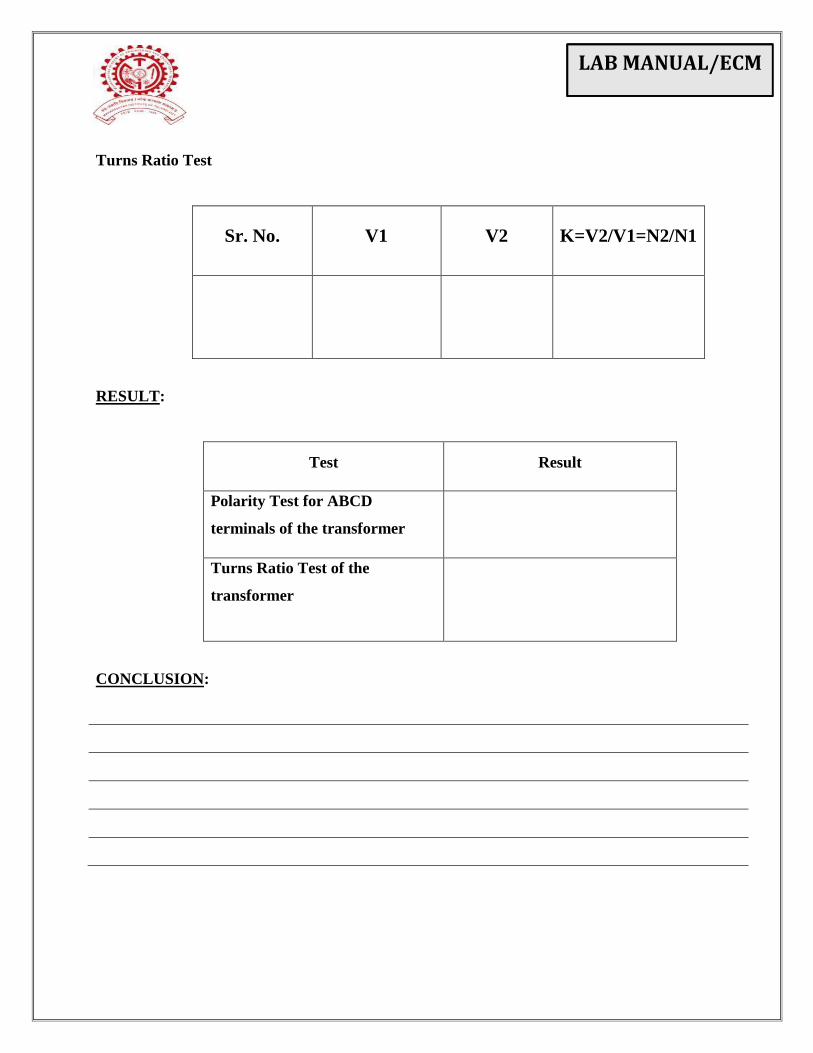
Turns Ratio Test
Sr. No. V1 V2 K=V2/V1=N2/N1
RESULT:
Test Result
Polarity Test for ABCD
terminals of the transformer
Turns Ratio Test of the
transformer
CONCLUSION:
LAB MANUAL/ECM
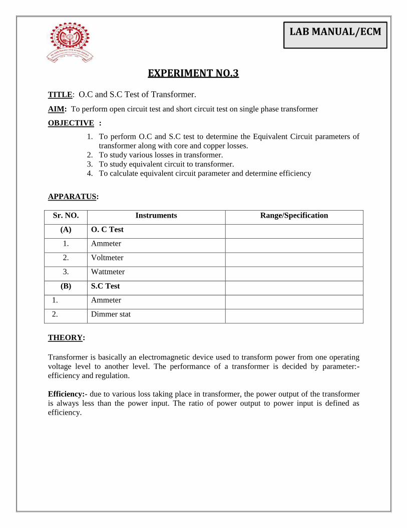
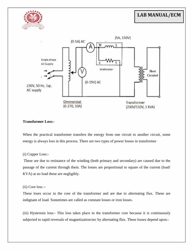
TITLE: O.C and S.C Test of Transformer.
AIM: To perform open circuit test and short circuit test on single phase transformer
OBJECTIVE :
1. To perform O.C and S.C test to determine the Equivalent Circuit parameters of
transformer along with core and copper losses.
2. To study various losses in transformer.
3. To study equivalent circuit to transformer.
4. To calculate equivalent circuit parameter and determine efficiency
APPARATUS:
Sr. NO. Instruments Range/Specification
(A) O. C Test
1. Ammeter
2. Voltmeter
3. Wattmeter
(B) S.C Test
1. Ammeter
2. Dimmer stat
THEORY:
Transformer is basically an electromagnetic device used to transform power from one operating
voltage level to another level. The performance of a transformer is decided by parameter:-
efficiency and regulation.
Efficiency:- due to various loss taking place in transformer, the power output of the transformer
is always less than the power input. The ratio of power output to power input is defined as
efficiency.
EXPERIMENT NO.3
LAB MANUAL/ECM
Regulation:- Due to internal impedance of the transformer (winding impedance) the load
voltage starts falling down as the load value is expressed in terms of regulation. It is defined as
the change in terminal voltage from no load to full load voltage.
O.C & S. C test method is commonly used for testing of transformer due to this reason
1. without actually loading the transformer directly desired results can be obtained. Hence it is
also called as indirect method of testing.
2. power requirement during the test are small.
3. result obtained are comparable with direct loading.
Equivalent Circuit:-
Analysis of transformer performance can be conveniently made by using its equivalent
circuit. An equivalent circuit of transformer is that circuit whose behavior is very similar to that
the transformer.
Open Circuit Test:-
In this case the transformer is excited from low voltage side (supply is given to low voltage side)
this is from the point of view of safety and convenience. Moreover, some time high voltage
supply may not be available for testing purpose. The secondary of the transformer is normally
kept open circuited and primary is being given the rated voltage. The main objective of this test
is to determine the shunt branch parameter of the equivalent circuit of the transformer. In
practice the no load current Io is small that V1 can be regarded as E1 by neglecting series
impedance with this approximate, the power input equals the core (iron) loss.
LAB MANUAL/ECM
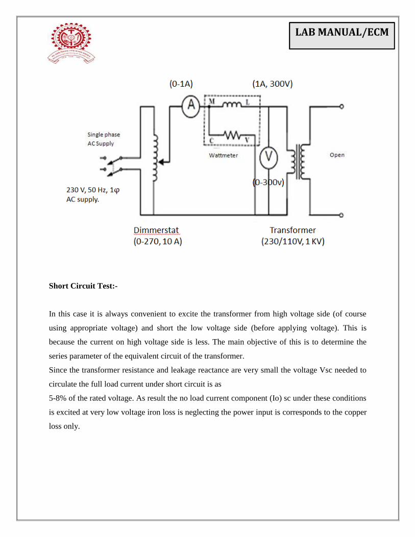
Short Circuit Test:-
In this case it is always convenient to excite the transformer from high voltage side (of course
using appropriate voltage) and short the low voltage side (before applying voltage). This is
because the current on high voltage side is less. The main objective of this is to determine the
series parameter of the equivalent circuit of the transformer.
Since the transformer resistance and leakage reactance are very small the voltage Vsc needed to
circulate the full load current under short circuit is as
5-8% of the rated voltage. As result the no load current component (Io) sc under these conditions
is excited at very low voltage iron loss is neglecting the power input is corresponds to the copper
loss only.
LAB MANUAL/ECM
Transformer Loss:-
When the practical transformer transfers the energy from one circuit to another circuit, some
energy is always loss in this process. There are two types of power losses in transformer
(i) Copper Loss:-
These are due to resistance of the winding (both primary and secondary) are caused due to the
passage of the current through them. The losses are proportional to square of the current (load/
KVA) at no load these are negligibly.
(ii) Core loss :-
These loses occur in the core of the transformer and are due to alternating flux. These are
indignant of load. Sometimes are called as constant losses or iron losses.
(iii) Hysteresis loss:- This loss takes place in the transformer core because it is continuously
subjected to rapid reversals of magnetization/sec by alternating flux. These losses depend upon:-
LAB MANUAL/ECM
(a) flux density
(b) Cycles of magnetization /sec (frequency)
(c) Volume of magnetic material.
Hysteresis loss = η Bm η
f v watts
Where η = Steinmetz constant depends on material of magnetic
Frame. (1.6 to 2.1)
Bm = Maximum flux density
f= supply frequency
v = volume of the core
Eddy Current Loss:-
These losses due to flow of eddy current in the magnetic material of the core and are given by
Eddy current loss = KeB2
m f2t2
watts/ unit volume
Where ke = eddy current constant
t = Thickness of the core
Core losses can be reduced by:
(i) Use of proper magnetic material (silicon steel with low values of Ke and η).
(ii) Use laminated construction
Both these losses (copper and core loss) reduce the efficiency and increase the heating effect.
PROCEDURE:
(A) O.C Test
1. Connect the circuit as per circuit diagram. (LV Coil on test side & Open HV Coil)
2. Select the proper ranges of the meter.
3. Ensure 0 Volt for dimmer stat with anticlockwise lock of rotor before turn on.
4. Increase the dimmer voltage slowly from 0 to 110 volts only (Rated Voltage).
5. Record the reading of all meter.

LAB MANUAL/ECM
(B) S.C Test:-
1. Connect the circuit as per circuit dig.(HV Coil on test side & Short LV Coil)
2. Select the proper ranges of the meter.
3. Ensure 0 Volt for dimmer stat with anticlockwise lock of rotor before turn on.
4. Increase the dimmer voltage from 0 to 10 volts only (To achieve
Rated current).
5. Record the reading of all meter.
OBSERVATIONS:
O.C Test
Vo in Volt Io in amp Wo in Watts
S.C Test
I/P Current Isc Input Voltage Vsc Input Power Wsc
LAB MANUAL/ECM
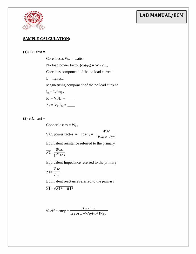
SAMPLE CALCULATION:-
(1)O.C. test =
Core losses Wo = watts.
No load power factor (cosφo) = Wo/VoIo
Core loss component of the no load current
Ic = Iocosφo
Magnetizing component of the no load current
Im = Iosinφo
Ro = Vo/Ic = ____
Xo = Vo/Im = ____
(2) S.C. test =
Copper losses = Wsc
S.C. power factor = cosφsc =
Equivalent resistance referred to the primary
=
Equivalent Impedance referred to the primary
=
Equivalent reactance referred to the primary
= √
% efficiency =
LAB MANUAL/ECM
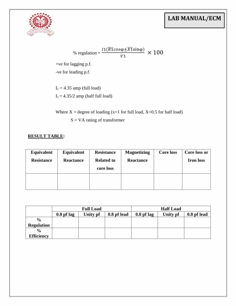
% regulation =
+ve for lagging p.f.
-ve for leading p.f.
I1 = 4.35 amp (full load)
I1 = 4.35/2 amp (half full load)
Where X = degree of loading (x=1 for full load, X=0.5 for half load)
S = VA rating of transformer
RESULT TABLE:
Equivalent
Resistance
Equivalent
Reactance
Resistance
Related to
core loss
Magnetizing
Reactance
Core loss
Core loss or
Iron loss
Full Load Half Load
0.8 pf lag Unity pf 0.8 pf lead 0.8 pf lag Unity pf 0.8 pf lead
%
Regulation
%
Efficiency

LAB MANUAL/ECM
CONCLUSION:
LAB MANUAL/ECM
TITLE: Speed control of DC motor using armature voltage and field current control method.
AIM: To study an effect on speed of DC shunt motor by,
A] Variation of excitation with constant armature voltage
B] Variation of armature voltage with constant excitation
APPARATUS:
Sr. NO. Instruments Range/Specification
1) DC shunt motor
2) Voltmeter DC
3) Ammeter DC
4) Rheostat
5) Rheostat
6) Tachometer
7) DC shunt motor
THEORY:
In DC motor, as soon as the armature starts rotating, dynamically induced emf is
produced in the armature conductors. The direction of this induced emf as found by Fleming’s
Right hans rule, is in direct opposition to the applied voltage. Hence it is known as back emp Eb.
Its magnitude can be calculated as,
A
PNZEb
60
volts.
Where, Ф = Flux per pole in Wb
P = No. of poles
N = Speed in rpm
Z= No. of armature conductors
A = No. of parallel paths.
PZ
ARIVN aa 60
As P, Z and A are constant for the motor,
EXPERIMENT NO.4
LAB MANUAL/ECM
aa RIV
KN
From above equation, it is obvious that, speed can be controlled by varying.
1. Flux/pole (Flux control method)
2. Armature resistance Ra of armature circuit (Rheostatic control method) and
3. Applied voltage (Voltage control method)
CIRCUIT DIAGRAM:

LAB MANUAL/ECM
PROCEDURES:
A] Speed variation by armature voltage control
1. Make connections as shown in the circuit diagram
2. With full excitation, apply a low voltage to the armature
3.The applied voltage is increased in steps noting down the speed and keeping the
Excitation constant.
B] Speed variation by flux control
1. Make connections as shown in the circuit diagram
2. Keep the rheostat in the field circuit is kept at its minimum, so the motor starts
with full excitation and hence with good starting torque.
3. Gradually increase the resistance in the field circuit so that the speed of the motor
increases.
4. Note down the value of field current and speed.
5. Keep the voltage applied to the armature constant throughout this part of the
experiment.
OBSERVATIONS:
A] Speed variation by armature voltage control
Constant field current = ______ Amp.
Sr No. Armature voltage (V) Speed (RPM)
1
2
3
4
5
6
7

LAB MANUAL/ECM
B] Speed variation by flux control
Constant armature voltage = ________ volts.
Sr No. Field current (A) Speed (RPM)
1
2
3
4
5
6
7
GRAPHS: Plot the graphs of,
1. Speed Vs Armature voltage
2. Speed Vs Field current
CONCLUSIONS:
LAB MANUAL/ECM
TITLE OF THE EXPERIMENT: Load test on three phase induction motor.
AIM: To study load test on 3 phase induction motor.
APPARATUS:
Sr. NO. Instruments Range/Specification
1) Induction motor
Coupled with DC Generator .
2) Lamp bank
3) Voltmeter
4) Voltmeter
5) Ammeter
6) Ammeter
7) Wattmeter
8) Rheostat
9) Tachometer
THEORY:
Load test on I.M. is used to determine speed, efficiency, power factor, stator current
torque & skip varying with load. Motor is loaded either by applying brake through belt pulley
arrangement or by loading D.C. generator of known efficiency. The effect of applying load on
above said quantity are,
1) Speed :- When I.M. is on no load, speed slightly below synchronous speed. Due to
induce e.m.f. in rotor winding.It produce torque require at no load. As load increases speed is
slightly reduced & e.m.f. induced in rotor & hence current in to produce high torque to match
with load torque.
2) Effect on slip :- Slip is expressed as difference in speed respectively to synchronously
rotating magnetic field. Slip is express as percentage of synchronous speed.
EXPERIMENT NO.5
LAB MANUAL/ECM
% s = (Ns-Nr) / Ns x 100
Where, Ns = Synchoronous speed
Nr = Rotor speed
Where synchronous speed depends upon frequency of stator supply voltage & no. of poles for
which motor is wound i.e Ns=120f / P.
Ns = 120f / P
If f & P both are constant then Ns is constant of particular morot with increasing in load
motor the motor speed decrease then slip increases.
3) Effect on stator current :-
Current drawn by stator is determined by two factors.
1) It’s one component is magnetic circuit current which required to maintain rotating field
and the second component is :
2) The component which produces a field which is equal & opposite to that formed by rotor
current. Rotor current increases with load so stator current increases with load.
4) Effect on power factor :-
Power factor of I.M. on no load is very low because of higher value of magnetic current.
High load p.f. increases because of power component increases. Usually ideal power factor is 1
for the motor. But I2R losses vary as square of load current. The low power factor is one of the
disadvantage .I.M. draws heavy magnetic current due to present of air gap between stator & rotor
which is not case with transformer, to reduce magnetic current, air gap should be kept as small as
possible.
5) Effect on efficiency :-
Losses occurring in motor as of 3 types.
1) losses in stator & rotor winding
2) Iron loss in stator & rotor core.
3) Friction & windage losses.
Iron losses are prepositional to stator flux density & stator supply frequency strength of
stator field is constant at all load . Iron losses in rotor very small as rotor iron losses can be
LAB MANUAL/ECM
neglected as compared to that of stator iron losses. The iron loss is dependent on load of the
motor.
Also speed of motor varies much with load, friction & windage losses can assumed to be
constant .Then efficiency of motor is given by
η =
If I2R loses are also constant, then efficiency of the motor increases. But I
2R losses
increase as square of the load current . Efficiency increases with load and the characteristics will
have a drooping curve at very high load.
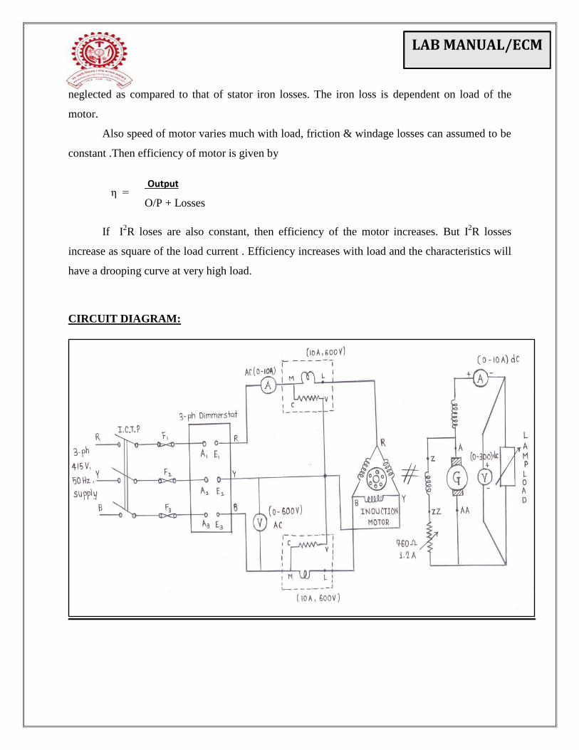
CIRCUIT DIAGRAM:
Output
O/P + Losses
LAB MANUAL/ECM
PROCEDURE:
1] Make the connections as per the circuits diagram.
2] Keep the rheostat in the field circuit of generator to its maximum position.
3] Keep all the switches of lamp bank in OFF position.
4] Switch on the supply and start the motor with the help of direct on line (DOL) starter.
5] Adjust the voltage of generator to rated value by varying the rheostat in the field circuit of
generator. Keep this voltage constant throughout the experiment.
6] Note down the no load reading. Then increase the load on the generator in steps by switching
ON lamps.
7] Note down readings for every step.
8] Switch off the lamp load and gradually reduce the generator voltage to the minimum value.
9] Switch OFF the supply to the induction motor
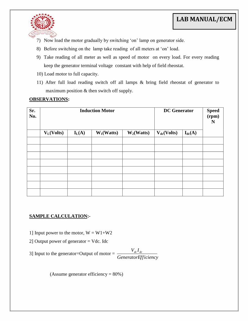
OBSERVATIONS:
Sr.
No.
Induction Motor DC Generator Speed
(rpm)
N
VL(Volts) IL(A) W1(Watts) W2(Watts) Vdc(Volts) Idc(A)
1)
2)
3)
4)
5)
6)
7)
CALCULATIONS:
1] Input power to the motor, W = W1+W2
2] Output power of generator = Vdc.Idc
3] Input to the generator=Output of motor = f f iciencyGeneratorE
IV dcdc
(Assume generator efficiency = 80%)
LAB MANUAL/ECM
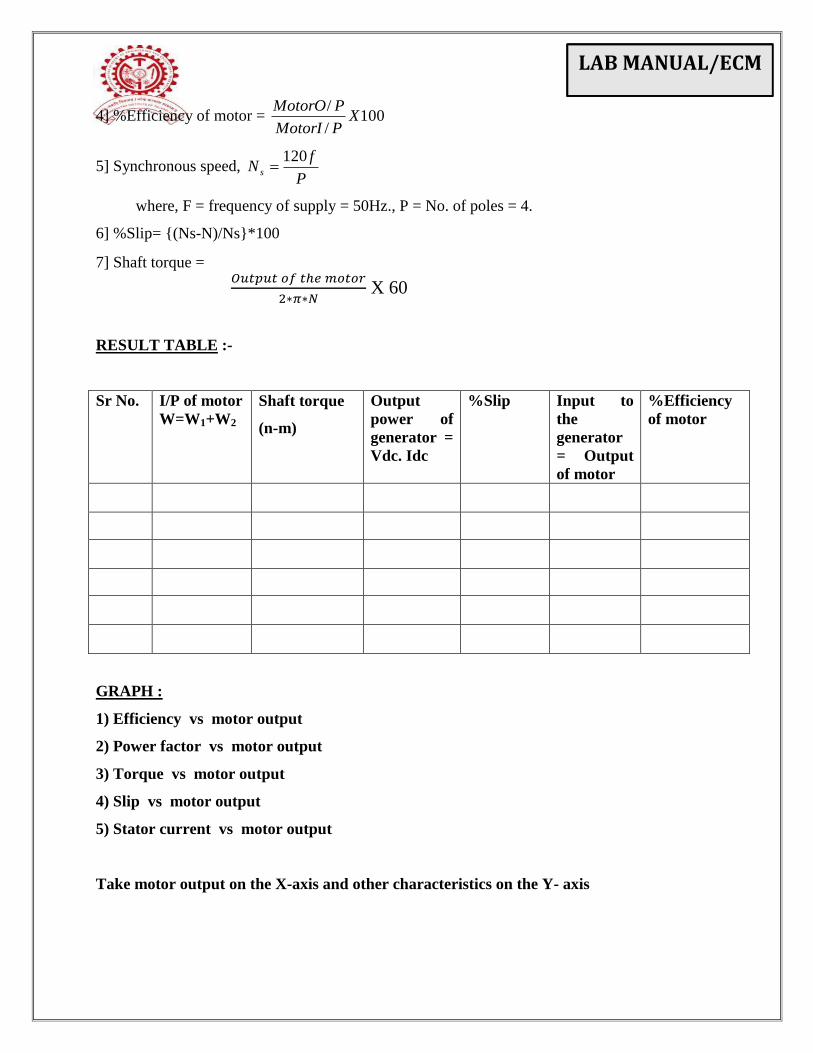
4] %Efficiency of motor = 100/
/X
PMotorI
PMotorO
5] Synchronous speed, P
fN s
120
where, F = frequency of supply = 50Hz., P = No. of poles = 4.
6] %Slip= {(Ns-N)/Ns}*100
RESULT TABLE:
Sr No.
I/P of motor
W=W1+W2
Output
power of
generator =
Vdc.Idc
%Slip Input to the
generator =
Output of
motor
%Efficiency of
motor
1
2
3
4
5
6
7
GRAPHS: Plot the graphs of,
1] Speed Vs Output Power
2] % Efficiency Vs Output Power
3] % Slip Vs Output Power
CONCLUSIONS:
LAB MANUAL/ECM
TITLE: Speed Torque Characteristics of 3 phase Induction Motor
AIM: To study Speed torque characteristics of 3 phase induction motor.
APPARATUS:
Sr. No. Apparatus Rating
1 Motor Generator set
2 Voltmeter
3 Ammeter
4 Wattmeter 1
5 Rheostat
6 Tachometer
7 Lamp Load
THEORY:
Load test on I.M. is used to determine speed, efficiency, power factor, stator current torque &
skip varying with load. Motor is loaded either by applying brake through belt pulley arrangement
or by loading D.C. generator of known efficiency. The effect of applying load on above said
quantity are,
1) Speed :- When I.M. is on no load, speed slightly below synchronous speed. Due to induce
e.m.f. in rotor winding.It produce torque require at no load. As load increases speed is slightly
reduced & e.m.f. induced in rotor & hence current in to produce high torque to match with load
torque.
2) Effect on slip :- Slip is expressed as difference in speed respectively to synchronously
rotating magnetic field. Slip is express as percentage of synchronous speed.
% s = (Ns-Nr) / Ns x 100
Where, Ns = Synchoronous speed
EXPERIMENT NO.6
LAB MANUAL/ECM
Nr = Rotor speed
Where synchronous speed depends upon frequency of stator supply voltage & no. of poles for
which motor is wound i.e Ns=120f / P.
Ns = 120f / P
If f & P both are constant then Ns is constant of particular morot with increasing in load
motor the motor speed decrease then slip increases.
3) Effect on stator current :-
Current drawn by stator is determined by two factors.
3) It’s one component is magnetic circuit current which required to maintain rotating field
and the second component is :
4) The component which produces a field which is equal & opposite to that formed by rotor
current. Rotor current increases with load so stator current increases with load.
4) Effect on power factor :-
Power factor of I.M. on no load is very low because of higher value of magnetic current.
High load p.f. increases because of power component increases. Usually ideal power factor is 1
for the motor. But I2R losses vary as square of load current. The low power factor is one of the
disadvantage .I.M. draws heavy magnetic current due to present of air gap between stator & rotor
which is not case with transformer, to reduce magnetic current, air gap should be kept as small as
possible.
5) Effect on efficiency :-
Losses occurring in motor as of 3 types.
4) losses in stator & rotor winding
5) Iron loss in stator & rotor core.
6) Friction & windage losses.
Iron losses are prepositional to stator flux density & stator supply frequency strength of stator
field is constant at all load . Iron losses in rotor very small as rotor iron losses can be neglected
as compared to that of stator iron losses. The iron loss is dependent on load of the motor.
Also speed of motor varies much with load, friction & windage losses can assumed to be
constant .Then efficiency of motor is given by
η = O/P + Losses
O/p
LAB MANUAL/ECM
If I2R loses are also constant, then efficiency of the motor increases. But I
2R losses increase as
square of the load current . Efficiency increases with load and the characteristics will have a
drooping curve at very high load.
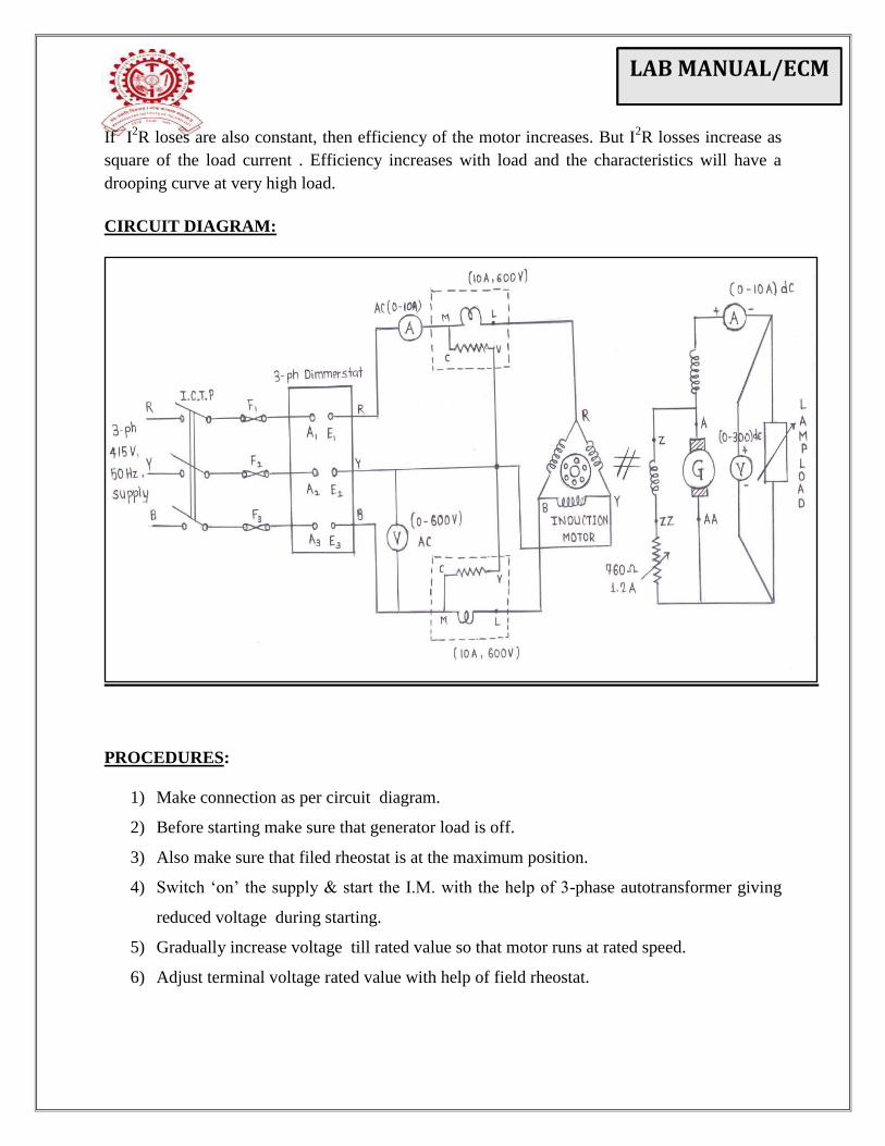
CIRCUIT DIAGRAM:
PROCEDURES:
1) Make connection as per circuit diagram.
2) Before starting make sure that generator load is off.
3) Also make sure that filed rheostat is at the maximum position.
4) Switch ‘on’ the supply & start the I.M. with the help of 3-phase autotransformer giving
reduced voltage during starting.
5) Gradually increase voltage till rated value so that motor runs at rated speed.
6) Adjust terminal voltage rated value with help of field rheostat.
LAB MANUAL/ECM
7) Now load the motor gradually by switching ‘on’ lamp on generator side.
8) Before switching on the lamp take reading of all meters at ‘on’ load.
9) Take reading of all meter as well as speed of motor on every load. For every reading
keep the generator terminal voltage constant with help of field rheostat.
10) Load motor to full capacity.
11) After full load reading switch off all lamps & bring field rheostat of generator to
maximum position & then switch off supply.
OBSERVATIONS:
Sr.
No.
Induction Motor DC Generator Speed
(rpm)
N
VL(Volts) IL(A) W1(Watts) W2(Watts) Vdc(Volts) Idc(A)
SAMPLE CALCULATION:-
1] Input power to the motor, W = W1+W2
2] Output power of generator = Vdc. Idc
3] Input to the generator=Output of motor = f f iciencyGeneratorE
IV dcdc
(Assume generator efficiency = 80%)
LAB MANUAL/ECM
4] %Efficiency of motor = 100/
/X
PMotorI
PMotorO
5] Synchronous speed, P
fN s
120
where, F = frequency of supply = 50Hz., P = No. of poles = 4.
6] %Slip= {(Ns-N)/Ns}*100
7] Shaft torque =
RESULT TABLE :-
Sr No.
I/P of motor
W=W1+W2
Shaft torque
(n-m)
Output
power of
generator =
Vdc. Idc
%Slip Input to
the
generator
= Output
of motor
%Efficiency
of motor
GRAPH :
1) Efficiency vs motor output
2) Power factor vs motor output
3) Torque vs motor output
4) Slip vs motor output
5) Stator current vs motor output
Take motor output on the X-axis and other characteristics on the Y- axis
𝑂𝑢𝑡𝑝𝑢𝑡 𝑜𝑓 𝑡ℎ𝑒 𝑚𝑜𝑡𝑜𝑟
∗𝜋∗𝑁 X 60

LAB MANUAL/ECM
CONCLUSION:-