Embed Size (px)
Citation preview
Chapter 1
Introduction
Polymers and polymer based composites are playing a crucial role in the day
to day life of human beings. With the advent of nanotechnology aided by the capacity
to modify the electrical, mechanical and magnetic properties of polymers, polymer
composites are increasingly playing a lead role in everyday life. Hence research on
these materials is pursued world wide by chemists, physicists and engineers alike. One
such realm where abundant amount of efforts are invested is in the area of new
products based on natural and synthetic rubber. This is because of the scope for
devicing new materials based on rubber and its potential to synthesise materials for
various applications such as flexible magnets, microwave absorbers and magneto
rheological materials. Rubber ferrite composites (RFCs) belong to this class of
materials derived by the incorporation of ferrite fillers in elastomer matrices.
Elastomers, which are otherwise nonmagnetic, are made into magnetic when ferrites
are incorporated into it. These magnetic fillers modify the mechanical, dielectric and
other physical properties of the elastomer. Significant changes in magnetic and
dielectric properties are observed for ferrites when the particle size is brought down to
nano metric dimensions. When ferrite nanoparticles are incorporated into rubber,
tremendous improvement in physicomechanical properties of the elastomer is realised.
Magnetism and magnetic materials have profound influence on human life.
Magnetic materials are employed in the development of most modern electronic
devices like computer chip memories, random access memory (RAM),
electromagnetic interference (EMl) shields, high density storage media, television set,
cell phone, refrigerator and washing machine. So, nanoscale magnetism and magnetic
materials are going to play a very dominant role in developing the technology of the
21 SI century.

cnapter 1
On the other side, polymers and polymer composites have established an
inevitable position in the area of material research. The presence of both natural and
synthetic rubber composites in different facets of human life such as transportation,
communication, development of space vehicles and satellites, as well as in other daily
use materials, chairs, automobile spare parts, pipes and toys, increase the importance
of these materials in material world. The useful properties of polymers and magnetic
materials pave the way for their combination to produce new composite materials with
improved characteristics.
The central theme of this thesis is the study on rubber ferrite composites with
special reference to the effect of nano ferrites on the physicomechanical properties and
on the dielectric, magnetic and microwave properties of RFCs. Therefore, a general
introduction is provided in the ensuing sections about elastomers, magnetic fillers and
magnetism, ferrites and rubber ferrite composites. Magnetic and dielectric properties
of ferrites are mainly dependent on their crystal structure. Structure of ferrites
resembles the crystal structure of MgAb04 and hence these types of ferrites are called
spinel ferrites. An overview of spine I structure is also given in the forthcoming
sections. Since the ferrite used for the preparation of RFCs in the present study is of
nano dimension, a short note is also given about the general methods of synthesis of
nano ferrites. Finally, the motivation and objectives of the present study are listed.
1.1 Elastomers
Different types of elastomers such as natural/synthetic and polar/non polar
are used for the preparation of rubber ferrite composites.
1.1.1 Natural rubber
Chemically, it is cis poly-isoprene characterised with low hysteresis, high
resilience and low water absorption. High tensile strength, tear strength, resilience and
high elongation at break are the major attractive features of natural rubber over
synthetic rubbers. Poor resistance to sunlight, oxygen and ozone are the drawbacks of
natural rubber compared to some synthetic rubbers. Compared to synthetic rubbers, it
is inexpensive. Synthetic rubbers have their own characteristic properties, which make
them special purpose rubbers and are used for the preparation of RFCs.
2

IntroauctUm
1.1.2 Ethylene propylene diene rubber
Ethylene propylene diene rubber (EPDM) is one of the most widely used
synthetic elastomers, having both special and general-purpose applications. It is a
copolymer of ethylene and propylene with a few percent of a third monomer namely a
diene. The termonomer can introduce un saturation to the otherwise saturated polymer.
The commonly employed comonomers for introducing unsaturation are,
H C
H-c/l~~ C-H " I 11
I1 H-C-H I I1
H-C I C C-H ~ /H~C/
C ' H H~
Dicyclopentadiene (DCPD)
If C
.,// '''", H H ' H-C I 'C=C-C"
1I H--C-H I
H--C. I c "-". ./ }.] C./ 12
H
Ethylidene norbornene (ENB)
CH 2=CH --CH')--CH =CH ---CH. - .,
1,4 Hexadiene
The structure of EPDM with ENB as the third monomer is given in figure 1.1.
Ethylene propylene diene terpolymer vulcanisate has been used extensively in high
frequency power cables, automotive radiator hose and white side walls of tyres
because of the exceptional capability to accept high loading of fillers and their
3
Chapter 1
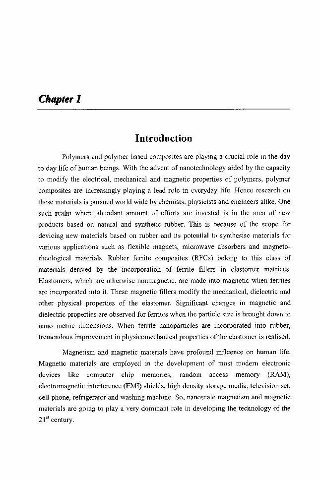
excellent ozone, heat and weathering resistance [1-4). EPDM vulcanisates exhibit
excellent electrical and mechanical properties when properly fonnulated [5].
Figure 1.1 Structure of EPDM with ENB as the third monomer
EPDM has found wide acceptance in wire and cable applications.
Unsaturation in the side chain renders it ozone resistant. It is also resistant to heat,
cold and moisture.
EPDM rubber can be vulcanised using either sulphur or peroxide as the
crosslinking agent. Peroxide cure gives better heat and ageing properties and low
compression set and better electrical properties. A number of factors such as the
ethylene/propylene ratio, nature and amount of the termonomer used, molecular
weight distribution, peroxide used and the type of fillers, influence the efficiency of
peroxide curing of EPDM [6,7]. The crosslink provided by peroxide vulcanisation is a
carbon-carbon bond which is similar in strength to every other bond in the polymer
back bone. Thus peroxide cured EPDM vulcanisate exhibits better compression set
resistance and resistance to heat and chemical attack compared to sulphur cured
vulcanisate. Moisture uptake and staining are less for the finished product prepared by
peroxide curing [8). In the present study, EPDM based RFCs are prepared by peroxide
vulcanisation.
1.1.3 Chloroprene rubber
Polychloroprene (CR), commercially known as neoprene is one of the widely
used synthetic rubbers with excellent heat, chemical and medium oil resistance [9].
Chloroprene monomer is used for the preparation of neoprene and structure of
neoprene is given in figure 1.2. There are three general purpose neoprene rubber, G,
W, and T types. Within each type, a number of grades of polymers are available with
4

Introtfuction
varying mooney viscosity, rate of crystallisation and other features. W type CR has
excellent raw polymer stability and better heat resistance. Their broad molecular
weight distribution imparts better processability [10]. CR has good flame resistance,
weather and ozone resistance. Because of its crystallising nature, neoprene gum
vulcanisate has inherent high tensile strength, elongation at break and wear resistance.
Figure 1.2 Structure of chloroprene rubber
Chloroprene rubbers are general1y vulcanised by the action of metal oxides
[11-l3]. The primary crosslinking agent is zinc oxide, which is used along with
magnesium oxide. Lead oxide is also used where high water resistance is required.
1.2 Magnetic fillers
Magnetism has fascinated humans for thousands of years. Nano scale
magnetic materials are increasingly used in diverse fields of applications. Synthesis of
magnetic materials with nano metric dimension helps in designing newer materials
with novel chemical, magnetic and electrical properties. Different types of magnetic
materials such as ferrites can be used for the preparation of magnetic composites.
Since the central theme of this thesis is magnetic nanocomposites based on ferrites and
rubbers, an introduction to different types of magnetism is provided below. Magnetic
materials are classified into different types based on their response to an external
magnetic field.
1.2.1 Magnetism
Magnetism is a result of moving charges. From an atomic view of matter,
there are two electronic motions: orbital and spin motion of electrons. These two
electronic motions are the source of macroscopic magnetic phenomena exhibited by
materials. Magnetic moment per unit volume or magnetisation M of a substance and
the magnetic flux density is related by the equation
5
Cli4pter I
1.1
where H is the applied field and I-l.o is the magnetic permeability of free space. The ratio
B -=/1 H
is called absolute permeability and
M -=X H
1.2
1.3
is called absolute susceptibility. ).l. and X are related by the expression
1.4
The magnetic susceptibility X is a useful property for characterising magnetic
materials.
Magnetism exhibited by different materials can be classified into five, depending upon
the value ofX and the response of the materials towards an external field [14-19].
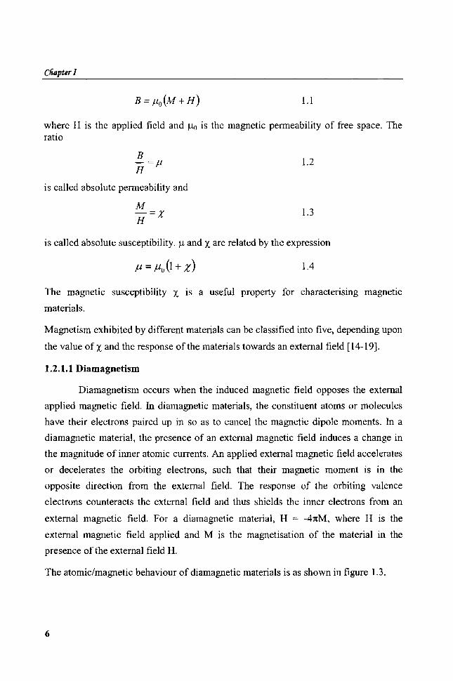
1.2.1.1 Diamagnetism
Diamagnetism occurs when the induced magnetic field opposes the external
applied magnetic field. In diamagnetic materials, the constituent atoms or molecules
have their electrons paired up in so as to cancel the magnetic dipole moments. In a
diamagnetic material, the presence of an external magnetic field induces a change in
the magnitude of inner atomic currents. An applied external magnetic field accelerates
or decelerates the orbiting electrons, such that their magnetic moment is in the
opposite direction from the external field. The response of the orbiting valence
electrons counteracts the external field and thus shields the inner electrons from an
external magnetic field. For a diamagnetic material, H = -41tM, where H is the
external magnetic field applied and M is the magnetisation of the material in the
presence of the external field H.
The atomic/magnetic behaviour of diamagnetic materials is as shown in figure 1.3.
6

®®~® @@@))@l)
®®~@ @®®®
M
Figure 1.3 Atomic/magnetic behaviour of diamagnetic materials
1.2.1.2 Paramagnetism
IntroauctiotJ
Paramagnetic substances are characterised by their intrinsic permanent
magnetic moments. Atoms or ions with one or more unpaired electrons exhibit
paramagnetism. An external magnetic field tries to turn the unfavourably oriented spin
moments in the direction of the external field. This results in an overall magnetic
moment that adds to the external magnetic field. The atomic/magnetic behaviour of
paramagnetic materials is represented in figure 1.4. Paramagnetic susceptability is
independent of the applied field and is temperature dependent. Curie's law governs the
temperature dependence of paramagnetic material. The magnetic susceptibility X is
related to the temperature in degree absolute by the equation X = C . X is small and T
positive for paramagnetic substances. In materials obeying Curie's law, magnetic
moments are localised at the atomic or ionic sites. There is no interaction between
neighbouring magnetic moments.
Paramagnetism is usually exhibited by transition or rare earth metal
compounds that possess unpaired electrons and it is known as spin paramagnetism. In
most of the solids, spin paramagnetism is observed. In crystals, the electron orbits are
essentially coupled to the lattice, which prevents the orbital magnetic moments from
turning into the field direction. Under such circumstances the orbital moments are said
to be quenched. Exceptions to this are the rare earth elements and their derivatives
with unpaired electrons in the deep lying '4f orbitals'. As the outer electrons from the
crystalline field of neighbouring ions shield these electrons, the orbital magnetic
7
ClUzpter 1
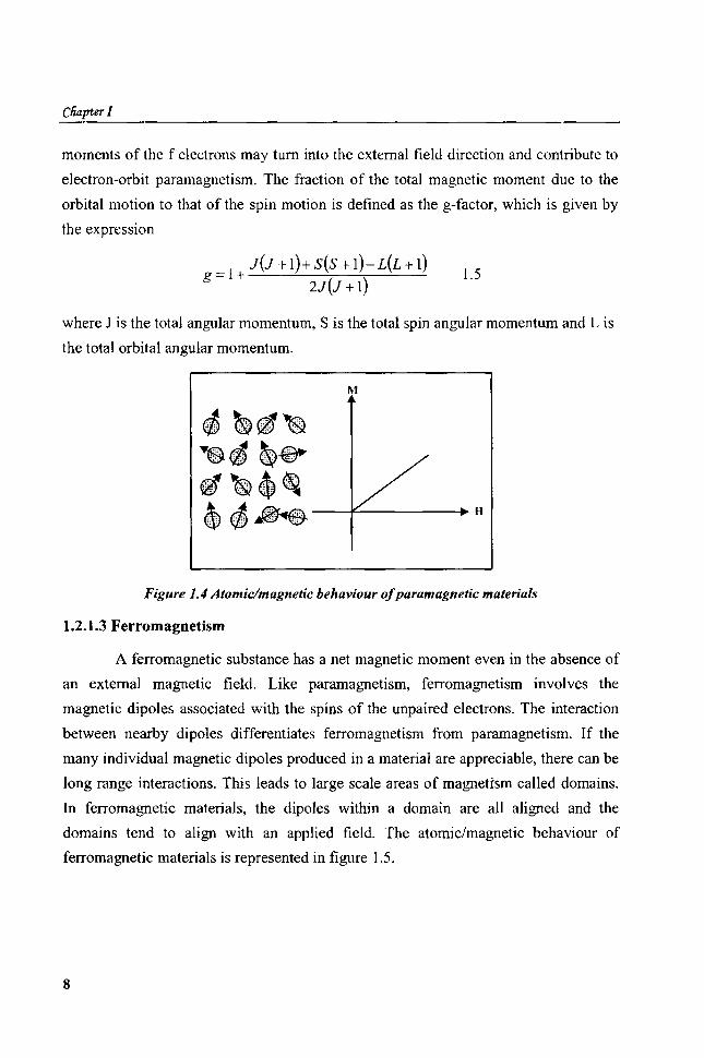
moments of the f electrons may turn into the external field direction and contribute to
electron-orbit paramagnetism. The fraction of the total magnetic moment due to the
orbital motion to that of the spin motion is defined as the g-factor, which is given by
the expression
= 1 + J(J + 1)+ S(S + 1)- L(L + 1) g 21(1 + 1) 1.5
where J is the total angular momentum, S is the total spin angular momentum and L is
the total orbital angular momentum.
M
Figure 1.4 Atomic/magnetic behaviour of paramagnetic materials
1.2.1.3 Ferromagnetism
A ferromagnetic substance has a net magnetic moment even in the absence of
an external magnetic field. Like paramagnetism, ferromagnetism involves the
magnetic dipoles associated with the spins of the unpaired electrons. The interaction
between nearby dipoles differentiates ferromagnetism from paramagnetism. If the
many individual magnetic dipoles produced in a material are appreciable, there can be
long range interactions. This leads to large scale areas of magnetism called domains.
In ferromagnetic materials, the dipoles within a domain are all aligned and the
domains tend to align with an applied field. The atomic/magnetic behaviour of
ferromagnetic materials is represented in figure 1.5.
8

Introauction
M
Figure 1.5 Atomic/magnetic behaviour offerromagnetic materials
A characteristic feature of a ferromagnetic substance is the magnetic
hysteresis. The energy expended in reorienting the domains from the magnetised state
back to the demagnetised state manifests into a lag in response to an applied magnetic
field, known as hysteresis. Another important property of ferromagnets is the Curie
temperature. For ferromagnetic materials, susceptibility X is large and positive and
varies with the absolute temperature. They obey theCurie-Weiss law, X = Cl (T-8),
where C and 8 are Curie Weiss constants. Above Curie temperature, ferromagnets
become paramagnets, since there is sufficient thermal energy to destroy the interaction
between atoms that create domain. Iron, cobalt and nickel are examples of
ferromagnetic materials. Gadollinium (Gd) which belongs to the rare earth family also
exhibit ferromagnetism. The curie temperature of Gd is 295 K. Chromium oxide is
another example of a ferromagnet.
1.2.1.4 Antiferromagnetism
In an antiferromagnet, exchange coupling exists between neighbouring
moments that causes the moments tq align in an antiparallel fashion. This anti parallel
alignment causes the system to have a small positive susceptibility, because an applied
magnetic field tends to align the spins and this induced alignment is larger than the
diamagnetism of the electron orbital. Figure 1.6 shows the atomic/magnetic behaviour
of antiferromagnetic materials. Similar to ferromagnets, the exchange energy can be
defeated at high temperatures and then the system becomes paramagnetic. The
temperature above which a ferromagnetic substance becomes paramagnetic is known
9

Chapter 1
as Neel temperature (T N)' For temperatures greater than T N, the susceptibility of a
ferromagnetic substance follows a paramagnetic Curie-Weiss law with a negative e, X
= C/(T+e). Most antiferromagnetics are found among ionic compounds such as
metallic oxides, sulfides and chlorides. Oxides of manganese and chromium are some
other examples of antiferromagnetic substances.
$~~~ ~ ~'$ 4 ~dP, , ~'$
1\1
---+""'------+H
Figure 1. 6 Atomic/magnetic behaviour of antiferromagnetic materials
1.2.1.5 Ferrimagnetism
Ferrimagnetism is observed in compounds which exhibit complex crystal
structures. Within these materials, the exchange interactions lead to parallel alignment
of atoms in some of the crystal sites and anti-parallel alignment in the other sites. The
material breaks down into magnetic domains, just like in a ferromagnetic material.
The magnetic behaviour is very similar, although ferrimagnetic materials usually have
lower saturation magnetisation. Ferrimagnets are similar to antiferromagnets in which
the opposing dipoles are not equal, so they do not cancel out. Therefore, these
materials exhibit a spontaneous magnetic moment and display hysteresis below Curie
temperature. Ferrimagnets are generally ceramic materials and they are good
insulators, making them very useful in preventing energy losses due to eddy currents
in transformers. Ferrites are typical examples of ferrimagnets and naturally occurring
magnetite and maghemite are examples of ferrimagnetic materials. The
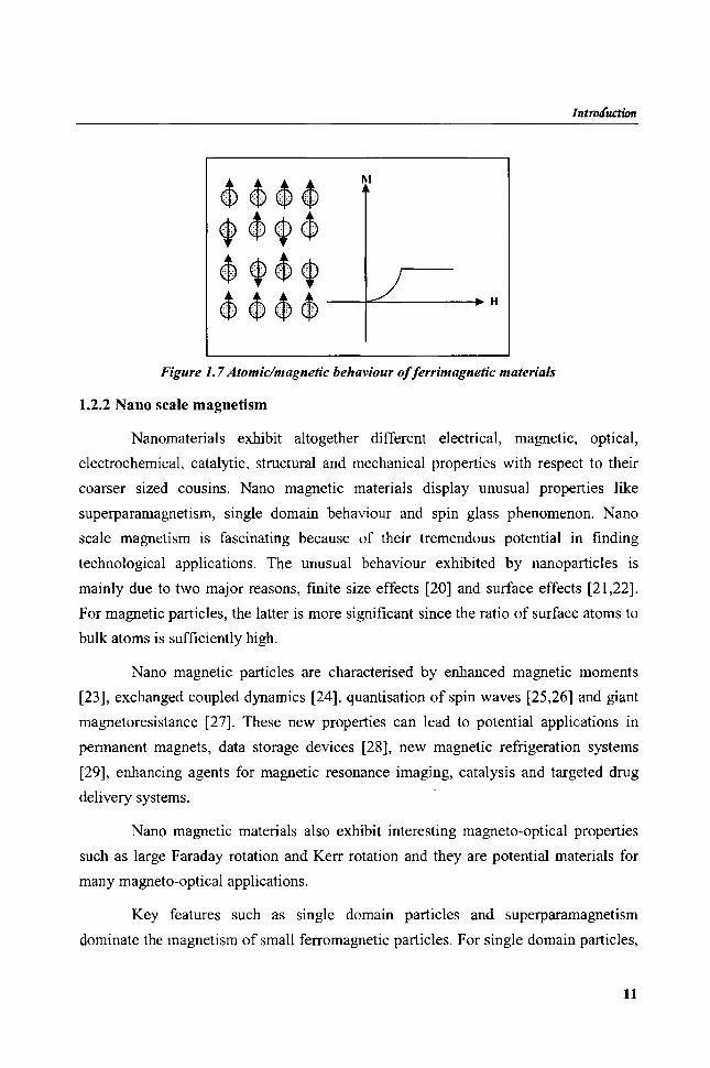
atomic/magnetic behaviour of ferrrimagnetic materials is depicted in figure 1.7.
10
IntrO/[uction
Figure 1. 7 Atomic/magnetic behaviour of ferrimagnetic materials
1.2.2 Nano scale magnetism
Nanomaterials exhibit altogether different electrical, magnetic, optical,
electrochemical, catalytic, structural and mechanical properties with respect to their
coarser sized cousins. Nano magnetic materials display unusual properties like
superparamagnetism, single domain behaviour and spin glass phenomenon. Nano
scale magnetism is fascinating because of their tremendous potential in finding
technological applications. The unusual behaviour exhibited by nanoparticles is
mainly due to two major reasons, finite size effects [20] and surface effects [21,22].
For magnetic particles, the latter is more significant since the ratio of surface atoms to
bulk atoms is sufficiently high.
Nano ma~'lletic particles are characterised by enhanced magnetic moments
[23], exchanged coupled dynamics [24], quantisation of spin waves [25,26] and giant
magnetoresistance [27]. These new properties can lead to potential applications in
pennanent magnets, data storage devices [28], new magnetic refrigeration systems
[29], enhancing agents for magnetic resonance imaging, catalysis and targeted drug
delivery systems.
Nano magnetic materials also exhibit interesting magneto-optical properties
such as large Faraday rotation and Kerr rotation and they are potential materials for
many magneto-optical applications.
Key features such as single domain particles and superparamagnetism
dominate the magnetism of small ferromagnetic particles. For single domain particles,
11
Cliapter 1
magnetisation reversal takes place through spin rotation where as in other cases, it
occurs due to the spin wall movement. Greater energy is required for spin rotation
resulting in higher coercivity for single domain system [30].
1.2.3 General methods employed for the synthesis of nanomaterials
The primary step in any investigation in material science is the preparation
and characterisation of materials. Any suitable method can be adopted for the
preparation of micron sized particles. However, the preparation of nanoparticles
requires some special methods that may be unique with respect to a particular
material. There are mainly two approaches for the synthesis of nanomaterials viz.
bottom up and top down approach.
In the bottom up approach, nanostructures are created, atom by atom or by
assembly of components consisting of a few thousand atoms or molecules. Processes
such as self organisation, self assembly or templating can be used to build a multitude
of nano architectures. Examples for bottom up approach are vapour phase processing
like physical and chemical vapour deposition, inert gas condensation and sputtering.
Chemical synthesis like sol-gel method, precipitation method and electrochemical
synthesis are based on bottom up principle.
Top down approach involves the use of conventional bulk starting materials
that include solid state processing like mechanical attrition, severe plastic
deformation, crystallisation of amorphous precursors and liquid-phase processing.
High energy ball milling (HEBM) is employed for attrition which can impart high
momentum to the milled powder through the high speed of rotation and revolution of
the vials which helps in obtaining high efficiency in low milling times.
Between the two methods, bottom up process is more advantageous. Surface
imperfections and strain will be less in bottom up process as it involves the formation
of nano structured materials via atom by atom growth. Careful control of the
preparative conditions in bottom up process ensures systematic tuning of the grain size
and other characteristics of the nanoparticles. Nanomaterials produced by these
methods mostly require further processing, sintering or thermal spraying to produce
useful structural materials.
12

Introdllcticrr
Several physical aerosol methods have been reported for the synthesis of nano
size particles of ceramic materials. These include gas condensation techniques (31,32],
spray pyrolysis [33-35] and thermochemical decomposition of metal-organic
precursors in flame reactors [36,37]. On the other hand, most widely used liquid phase
chemical method is sol-gel method [38,39]. Other wet chemical methods, including
microemulsion [40,41] and co-precipitation have also been widely used [42].
1.2.3.1 Vapour condensation method
In this method, a super saturated vapour of the metal is condensed under inert
convection of gas inside a chamber. A high pressure of inert gas is usually needed to
achieve super saturation. Frequent collision with the gas atom decreases the diffusion
rate of atoms from the vapour source region and cools the atoms. The powder is
oxidised by allowing oxygen into the chamber. This post oxidation must be carried out
slowly. Due to the highly exothermic reaction, particles heat up for short times to
temperature as high as 1000°C resulting in their agglomeration into large particles by
rapid diffusion processes. A subsequent annealing process at higher temperature is
often required to complete the oxidation.
Advantages of this method over other techniques are versatility, ease of
performance and analysis and production of high-purity products. This method is also
employed to produce films and coatings. The disadvantages are high production cost
and low yield. Heating techniques have other disadvantages like the possibility of
reaction between the metal vapors and the heat source materials. This method can not
be used to prepare a wide variety of materials as the operating temperatures are
limited by the choice of the source material.
1.2.3.2 Spray pyrolysis
In this method, precipitation from a concentrated solution of cations can be
performed by solvent evaporation. The starting precursor for this method is sol or
suspension of appropriate salts. From this, aerosol droplets are prepared by
nebulisation or atomisation of the starting sol at high pressure. The solvent is rapidly
evaporated by an upward stream of hot gas. The microporous particles thus produced
are compacted and calcined to produce the ceramic powders.
13

Chapter 1
Advantages of this method include the formation of high purity and
homogeneous products with nano metric dimensions. Since each particle/droplet
undergo the same reaction conditions, no subsequent milling is necessary. Major
disadvantages of this process are the requirement of large amount of solvents and
difficulty in scaling up of the process. Use of nonaqueous solvents increases the cost
of production, so this process is limited to the aqueous systems.
1.2.3.3 Thermochemicallflame decomposition of metal organic precursors
This is an effective method for the preparation of ceramic nanoparticles. This
process is also referred to as chemical vapor condensation (evC). The starting
materials are liquid chemical precursors which are vapourised and then oxidised in a
combustion process using a fuel oxidant mixture. The process involves the rapid
thermal decomposition of a precursor carrier gas stream at reduced pressures with
simultaneous decomposition of the condensed product particles on substrates.
Organometallic based synthesis, carried out at high temperatures, facilitates the
removal of crystalline defect and results in high quality magnetic nanoparticles.
1.2.3.4 Reverse microemulsioD method
This is one of the promising methods for the preparation of nano crystalline
materials. In this method, micelles are formed by adding surfactants, dissolved in
organic solvents to the aqueous solution of reactive precursors. Nanoparticle synthesis
inside the micelles can be achieved by hydrolysis of reactive precursors or by
precipitation reactions of metal salts. Solvent removal and subsequent calcination lead
to the final product. The final properties of the product such as particle size, particle
size distribution, agglomeration and final phase formation of the ceramics are affected
by several parameters such as the concentration of the reactive precursor in the micelle
and mass percentage of the aqueous phase in microemulsion. Microemulsion
techniques are often carried out at low temperatures but with the disadvantage that the
particles are less crystalline and more polydispersed.
1.2.3.5 Sol- gel method
Sol-gel method is widely used for the preparation of a large number of
inorganic and inorganic/organic composite materials. The process involves the
14
I ntrocfuction
preparation of a sol and typically used for the preparation of metal oxide via the
hydrolysis of reactive metal precursors. The sol of the metal salt is prepared by mixing
concentrated solutions containing the cations of interest, with an organic solvent
(usually alcohol) as the dispersion medium. The solution is then destabilised by
adding water. The presence of water modifies the pH of the sol and reduces the
repulsion between particles. This results in a large increase in the viscosity of the
system, leading to the formation of a gel.
Addition of water to alcoholic solution of alkoxide results in the formation of
corresponding hydroxide. Condensation of hydroxide molecules by elimination of
water leads to the formation of a network of metal hydroxide. When all hydroxide
species are linked in one network structure, gelation is achieved and a dense porous
gel is obtained. The gel is a polymer of three dimensional skelton surrounding
interconnected pores. Removal of the solvents and appropriate drying of the gel results
in an ultrafine powder of the metal hydroxide. Further heat treatment of the hydroxide
leads to the corresponding ultrafine powder of the metal oxide.
Solvent removal from the gel is achieved by two ways. Drying is achieved by
evapouration under normal conditions and the gel network shrinks as a result of
capillary pressure and the hydroxide obtained is known as xerogel. Aerogels are
obtained when drying is being done using a high pressure autoclave at temperatures
higher than the critical temperature of solvents. Aerogel powders have higher
porosities and larger surface areas than analogous xerogel powders (19].
1.2.4 Application of magnetic materials
It is well known that magnetism and magnetic materials have unprecedented
role in data storage and magnetic recording. A novel substitute for the conventional
magnetic materials in these fields is magnetic nano wires. For long term storage,
magnetic materials should have a reasonably high coercivity, because external
magnetic fields should not alter the magnetisation. At the same time it should not be
too large if the medium is to be reusable. Ferromagnetic nano wires encapsulated
within carbon nano tubes provide an ideal system for recording. Small size anisotropy
and the single isolated domain nature of the encapsulated iron crystals provide higher
coercivity. Due to the graphite protecting cover, the magnetic properties of entrapped
15

Chapter 1
nano wires do not degrade with time [43,44]. Magnetic nanocomposites should also
find applications in the fabrication of fine particle magnets, for use in magnetic inks
and as toners in xerography.
Magnetoelastic materials are another class of technologically important
magnetic materials. These materials give the possibility of converting very small
mechanical stress into electrical voltage. Magnetic devices for detecting parked
vehicles are developed based on the principle of magnetoelastic resonance. Coding
devices are developed based on magnetoelastic resonators which rely on the variation
of the Youngs modulus with the bias field [45]. Frequency dependence of
permeability of the nanocrystalline ribbons have been made use in devices such as
current-compensated chokes, saturable reactors and inverter transformers for
integrated services digital network (ISDN) telecommunications [46].
Magnetorheological elastomers composed of ferromagnetic particles
dispersed in a non-ferromagnetic elastomer matrix susceptible to elastic deformations
constitute a very interesting group of magnetic materials [47]. Magnetorheological
elastomers are used for the production of controlled vibration dampers [48].
Superparamagnetism is a unique feature of magnetic nanoparticles and is
crucially related to many modem technologies like ferrofluid technology [49],
magnetocaloric refrigeration [50] magnetic resonance imaging (M RI) [51] and
magnetically guided drug delivery. Ferrofluids are stable suspensions of nano
magnetic particles in a suitable base fluid like oil or water. They are of great research
interest because of their numerous physical, engineering and medical applications.
These smart fluids show many interesting magneto-optical properties. Some of the
engineering applications of these rheological fluids are in making rotary seals,
pressure sensors and loud speakers. Ferrofluids can serve as contaminant exclusion
seals, vacuum seals and dampers in stopper motors. With improvement in
performance and production cost, nano ferrofluids may find applications as cooling
fluids, nano scale bearings and in magnetically controlled heat conductivity [52]. They
are also widely used in bio medical fields especially in cancer therapy [53].
Tumor specific nanocomposites are developed and the technique is named as
magnetic hyperthermia. Magnetic nanoparticles are specifically attached to the cancer
16
Introduction
cells and under the application of an ac electric field, the particles become selectively
heated, damaging (hyperthermia) or destroying (thermoablation) the attached tumor
cell. This method has immediate effect without any side effects. Magnetic
nanoparticles can also be used for controlled drug delivery at a predetermined site
within the body [54-56].
Ferromagnetic semiconductors are obtained by doping magnetic impurities in
host semiconductors. They are key materials for spin electronics (spintronics) in
which the correlation between the charge and spin of electron is used to bring about
spin dependant electronic functionality such as giant magneto resistance (GMR) and
spin field effect.
Magnetic particles coated with protective and functional materials such as
silica can easily be prepared by sol-gel method or liquid phase coating process [57].
Magnetic particles embedded in polymer matrices have been synthesised for the
fabrication of conductive, superparamagnetic plastic films [58-63]. Deposition of
conductive polymer chains and magnetic nanoparticles in a layer by layer fashion may
lead to new properties such as GMR and novel organic based nano structured GMR
materials. Other than serving as a lossless transformer, the nano magnets can act as
miniature switches or sensors. Polymer based nanocomposites can be used as a
dielectric layer in electronic packing applications.
A new class of flexible magnetic composites can be prepared by incorporating
ferrite materials into elastomer medium which are named as rubber ferrite composites.
Rubber ferrite composites find applications in many devices because of their easy
mouldability and microwave absorbing properties [64,65].
1.3 Ferntes
Ferrites are mixed metal oxides with Iron (111) oxides as their mam
component. Based on their crystal structures, ferrites are classified into three types
namely spinels, garnets and magnetoplumbites. They are shown in table 1.1.
Simplest among the ferrites are the spinel ferritcs. The structure of ferrites
resembles that of the mineral spinel MgAI20 4• Spinel ferrites can again be categorised
into two namely normal and inverse spinels. The unit cell of a spinel structure consists
17
CliapteT 1
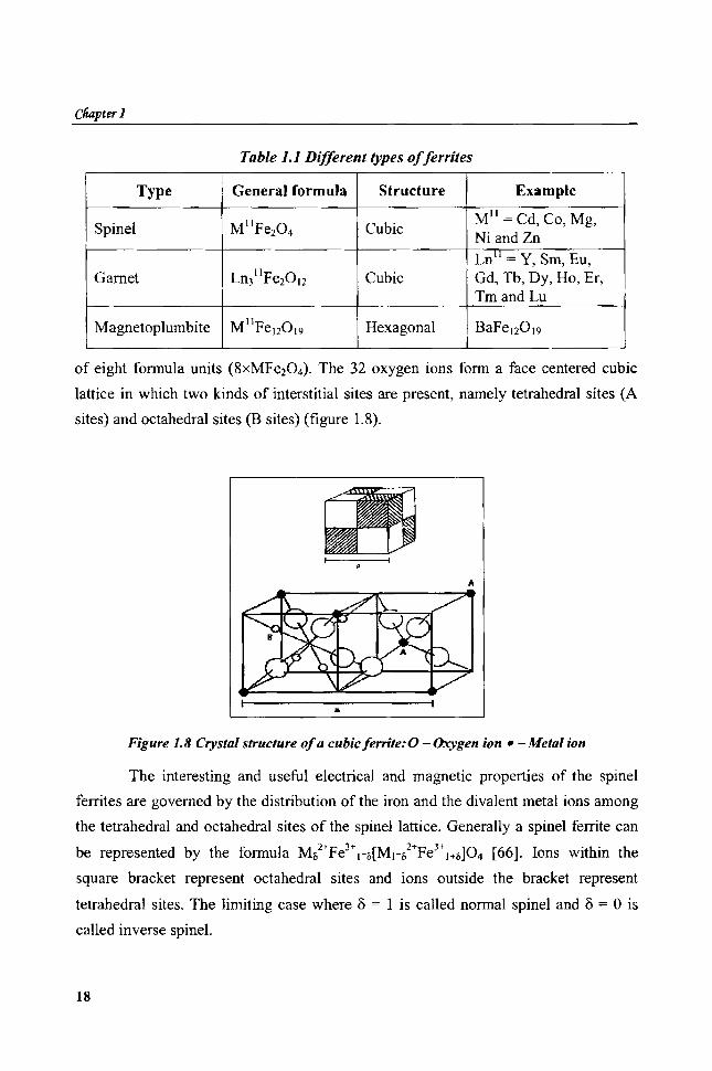
Table 1.1 Different types offerrites
Type General formula Structure Example
Spinel M" Pe20 4 Cubic MII = Cd, Co, Mg, Ni and Zn Ln'l = Y, Srn, Eu,
Garnet Ln31'Pe2012 Cubic Gd, Tb, Dy, Ho, Er, Tmand Lu
Magnetoplumbite M'l FeJ20 '9 Hexagonal BaPe'20 19
of eight formula units (8xMFe204). The 32 oxygen ions form a face centered cubic
lattice in which two kinds of interstitial sites are present, namely tetrahedral sites (A
sites) and octahedral sites (B sites) (figure 1.8) .
•
Figure 1.8 Crystal structure of a cubic ferrite: 0 - Oxygen ion. - Metal ion
The interesting and useful electrical and magnetic properties of the spinel
ferrites are governed by the distribution of the iron and the divalent metal ions among
the tetrahedral and octahedral sites of the spinel lattice. Generally a spinel ferrite can
be represented by the formula M&2+Pe3+n[Mn2+Fe3+'+O]04 [66]. Ions within the
square bracket represent octahedral sites and ions outside the bracket represent
tetrahedral sites. The limiting case where 0 = 1 is called normal spinel and 0 == 0 is
called inverse spine\.
18

IntroauctWn
Site preference of the cations between the octahedral site and tetrahedral site
are explained using crystal field theory by Dunitz and Orgel [67] and also by McClure
[68] where as Blasse [69] has used a simplified molecular orbital approach. According
to the crystal field theory, the five degenerate 3d orbitals in an octahedral field are
split into a lower triplet (t2g) and higher doublet (e2g). These two levels are separated
by an energy difference of 10 Dq. This splitting of orbitals is reversed when the
cations occupy a tetrahedral site. In this case, e2g orbitals become lower and t2g orbitals
become higher energy levels. Thus, the crystalfield stabilisation energy of a cation
will be different in both tetrahedral and octahedral coordination. This determines the
cation distribution in ferrites [70].
Tn the case of NiFe204, Ni2+ ion with d8 configuration contains two unpaired
electrons irrespective of the A or B site. But crystal field stabilisation energy is more
in B site, hence preferably occupies octahedral site, thus forming an inverse spinel
structure. ill addition to simple binary spinels, a number of mixed ferrites are also
possible by partial substitution of cations, either in A or B site. As the properties of
mixed ferrites are highly dependant on the composition, ferrites with predetermined
material characteristics can be designed by properly adjusting the composition. A
large number of mixed ferrites are studied and reported, among this the extensively
studied one is Ni-Zn ferrite.
In addition to the above mentioned forms, some ferrites exhibit distorted
spine! structures. Examples are magnetite (Fe304) and maghemite (y-Fe203). y-Fe203
has a cation deficient spinel structure with a fraction of octahedral sites occupied by
vacancies at all temperatures.
1.3.1 Magnetic properties of ferrites
Ferrites are important ferrimagnetic materials. In ferrites, the metallic ions
occupy two crystallographic sites; octahedral sites and tetrahedral sites. Three kinds of
magnetic interactions are possible between the metallic ions, through the intermediate
0 2• ions, by super exchange mechanisms namely A-A, B-B and A-B interactions.
These interaction energies are negative and induce an anti parallel orientation (as
proposed by Neel in 1948). In ferrites, A-B interaction predominates. Thus spins of A
19
Cliapter 1
site and B site ions In ferrite are oppositely magnetised with a resultant magnetic
moment equal to the difference between those of A and B site ions.
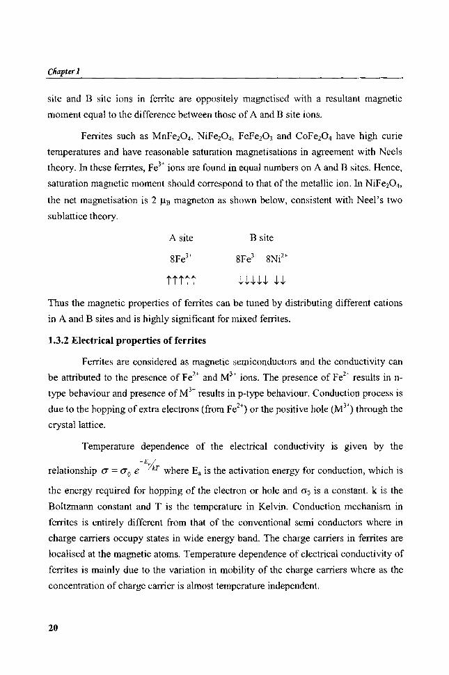
Ferrites such as MnFe204, NiFe204, FeFe203 and CoFe204 have high curie
temperatures and have reasonable saturation magnetisations in agreement with Neels
theory. In these ferrites, Fe3+ ions are found in equal numbers on A and B sites. Hence,
saturation magnetic moment should correspond to that of the metallic ion. In NiFe204,
the net magnetisation is 2 J.!1l magneton as shown below, consistent with Neel's two
sublattice theory.
A site B site
ttttt
Thus the magnetic properties of ferrites can be tuned by distributing different cations
in A and B sites and is highly significant for mixed fenites.
1.3.2 Electrical properties of ferrites
Ferrites are considered as magnetic semiconductors and the conductivity can
be attributed to the presence of Fe2+ and M);- ions. The presence of Fe2
" results in n
type behaviour and presence of M3+ results in p-type behaviour. Conduction process is
due to the hopping of extra electrons (from Fe2+) or the positive hole (M3!) through the
crystal lattice.
Temperature dependence of the electrical conductivity is given by the -E /
relationship a = aD e IkT where Ea is the activation energy for conduction, which is
the energy required for hopping of the electron or hole and Go is a constant. k is the
Boltzmann constant and T is the temperature in Kelvin. Conduction mechanism in
ferrites is entirely different from that of the conventional semi conductors where in
charge carriers occupy states in wide energy band. The charge carriers in ferrites are
localised at the magnetic atoms. Temperature dependence of electrical conductivity of
ferrites is mainly due to the variation in mobility of the charge carriers where as the
concentration of charge carrier is almost temperature independent.
20

Infroiluctjqn
Dielectric properties of fenites depend on several factors including the
method of preparation, chemical composition and grain structure and size. Dielectric
properties of solids can be explained based on phenomenon like polarisation. In
polycrystalline ferrites, three principle mechanisms of polarisation exist within a
frequency spectrum extending from zero frequency to frequencies corresponding to
ultra violet radiations. The electronic contribution arises from the displacement of
electron shell relative to the nucleus. Ionic polarisation comes from the displacement
of charged ion with respect to other ions and dipolar polarisation due to the orientation
of electric dipole in an external field. In addition to this, in heterogeneous materials
interfacial polarisation occurs due to the accumulation of charges at structural
interfaces. Frequency dependence on the polarisability due to several contributions is
represented in figure 1.9.
E mt@'rla[e
Ionic
GHz Optical L-------~----~--______________ ~~Igoo
19ro
Figure 1.9 Frequency dependence of the several contributions to the dielectric polarisability.
1.3.3 Different methods for the preparation offerrites
A number of chemical methods such as micro emulsion or reverse micelle
method, co-precipitation method, sol-gel method and synthesis from different organic
precursors are reported for the preparation of nano fenites.
1.3.3.1 Ceramic method
This is one of the earliest and most popular methods used for the synthesis of
fenite materials. The particle size of the materials prepared by this method is often
found to be of micrometric dimension. Required precursors are mixed in appropriate
21
ClUzpter I
molar ratio and sintered at very high temperature which results in the formation of
crystalline materials [71-74].
The disadvantage of ceramic method is that it is highly difficult to control the
stoichiometirc composition and final structure. Since this technique requires
prolonged heating at very high temperatures, some of the constituents may evapourate
thereby resulting in alteration of the desired stoichiometry [75].
1.3.3.2 Co-precipitation method
In cold co-precipitation method, the precursors are taken in the appropriate
molar ratio in an aqueous medium at an appropriate pH and temperature. The
precipitate is then heated at high temperatures to obtain crystalline ferrite materials
[76].
Nano crystalline ferrite materials can successfully be prepared from different
organic precursors. Citrate and oxalate precursors are used for the synthesis of ferrite
nanopartic1e. This solution method allows the atomic scale mixing of the constituent
cations and allows the formation of ferrite particles at low temperatures [77,78].
C. Caizer and M. Stefanescu had reported the preparation of Ni-Zn ferrite powder
from the glyoxylate precursor. It is practically a low temperature method. The reaction
efficiency is nearly 100% and high purity products are formed [79].
1.3.3.3 Sol-gel technique
This is one of the easiest routes for the synthesis of nanomaterials [80-82]. In
this method, reactants, preferably, metal nitrates or acetates are completely dissolved
in a suitable organic solvent and the solution is allowed to react at low temperature
until a gel is formed. The gel is then heated at high temperature to obtain the desired
final product. The detailed mechanism and sol-gel chemistry is provided in section
1.2.3.5.
1.3.3.4 High energy ball milling
In this method, mechanical energy is utilised for the synthesis of nanoparticles
from micro particles. Here, due to the very high rotation and revolution, the energy
22
Intrrxfuction
imparted to the material is very high. The properties of nano phase materials
synthesised by this method are dependant on ball milling conditions [83].
1.3.4 Applications of ferrites
Polycrystalline ferrites are good dielectric materials with low conductivity and
have a wide field of technological applications. Ferrites are used extensively in many
electronic devices, because of their high permeability in the radio frequency region,
high electrical resistivity, mechanical hardness and chemical stability [84,85].
Hexagonal ferrites based on barium ferrite are efficient replacements for the
metallic magnets in recording media and in microwave devices [86]. High stability in
air, non metallic electrical properties, corrosion resistance and sharp switching fields
make hexagonal ferrites superior to metallic magnets [87]. Among the different types
of hexaferrites, M-type barium hexaferrite has been intensively studied as a material
for permanent magnet, high density magnetic recording media and microwave devices
[88,89]. Anisotropic hexaferrites are highly used in loud speakers and in dc motors.
Stepping motors based on ferrite materials are needed in floppy-disc drivers, printers
and other computer peripherals.
Ferrites are also used in antennas to transform an electromagnetic signal
transmitted through the air into an electric signal. The application of ferrites at
microwave frequencies (1-300 GHz) is based on electromagnetic wave propagation
phenomena. Ferrite isolators are typically employed to isolate source from load in
microwave systems. Circulators and phase shifters based on ferrites are typically used
in microwave antenna systems. As microwave absorbers, ferrites can be used to
suppress electromagnetic interference [90-92].
Ferrite nanoparticles possess superior magnetic properties when compared to
their bulk counter parts. In ferrite nanopartic1es, a strong decrease in saturation
magnetisation and an enhancement in coercivity in comparison to the bulk material
have been reported [93]. Property enhancement of ferrite nanopartic1es makes them
suitable for applications in electronics, bioprocessing, magnetic resonance imaging
and ferrofluids [94].
23

Cliapter 1
Mixed ferrites based on Ni-Zn and Mn-Zn are the most widely used materials
for different applications. These types of ferrites are used in mab1fletic cores of read
write heads for high-speed digital recording. Zn-Mn ferrites are important electronic
ceramic materials because of their high magnetisation polarisations and electrical
resistivity. These are the main constituents of transformer cores, inductors, converters
and yokes [95]. High resistivity and low eddy current loss of Ni-Zn ferrite makes them
adaptable for high frequency applications [96]. Mg-Zn ferrites are used as materials
for coil cores like deflection coils for picture tubes in TV and computer memories
[97].
1.4 Rubber ferrite nanocomposites
Development of magnetic nanocomposites leads to new composite materials
such as plastic magnets or magneto polymers [45,98]. Incorporation of magnetic
fillers into a polymer matrix produces plastic magnets. Rubber ferrite composites are
magnetic polymer composites, prepared by the incorporation of ferrites into rubber
[99, 100]. They have wide range of technological applications. These flexible magnetic
materials have excellent performance characteristics and often on par with ceramic
magnetic materials. The unique advantages of RFCs are their easy processability and
mouldability into convoluted structures. This makes them superior in many respects
over conventional ceramic magnets. The degradation of the polymeric matrix limits
the application potential of these materials at temperature above 200°C. However,
polymer magnets are increasingly used as special purpose composites.
Addition of magnetic fillers to a polymer host medium affects its
processability and mechanical properties; where as the magnetic properties of the
fillers are also affected by encapsulating them with polymeric medium. Magneto
polymers with tailored properties are made with suitable selection of magnetic tillers
and host medium [10 I]. The concentration and orientation of the magnetic particles
and degree of interaction of the filler with the matrix are important factors of concern
in tailor making materials. In selecting the matrix, the mechanical, viscoelastic and
chemical properties of the matrix must be taken into consideration. The compatibility
of the matrix with magnetic particles is a significant factor. Advantages of plastic
magnets over their metallic and ceramic counterparts include light weight and low
24
IntrolfuctUm
cost, resistance to corrosion, ease of machining and preparation and capability of high
production rates [lO2,103].
Polymer composites are important commercial materials, which find
application in vibration damping, electrical insulations, thermal insulations and high
performance composites for use in aircraft. Rubber ferrite composites are one such
special purpose composite in which the flexibility and mechanical properties of an
elastomer and magnetic properties of ferrite filler have been effectively utilised.
The impregnation of magnetic fillers in the matrix imparts magnetic
properties and appreciably modifies the physical properties of the matrix. Proper
selection of the elastomer as well as the ferrite is important for achieving the desired
properties. The polymer must have appropriate physical properties and reasonable
stability. Factors like percolation limits, nature of the matrix namely saturation!
unsaturationl polarity all influence the final properties of the composites. Both natural
and synthetic rubbers can be used as the host matrix for RFCs.
Magnetic properties of the RFCs like saturation magnetisation, coercivity and
remanant magnetisation can easily be controlled by proper selection of the magnetic
filler. Both hard and soft ferrites are used as filler. Soft ferrites like nickel-zinc ferrite
and manganese zinc ferrite are incorporated in the polymer matrices (both natural and
synthetic) to produce RFCs [104-106]. Rubber ferrite composites based on natural
Isynthetic rubbers and hard ferrites like strontium ferrite and barium ferrite are also
reported [107-109].
One of the important factors that determines the processability and properties
of RFCs is the particle size of the filler. When the size of the filler is in the nano
regime, greater enhancement of mechanical properties can be anticipated. Smaller the
particle size, larger the surface area and greater is the polymer-filler interface
interaction. Thus, ferrite particles can act as a semi reinforcing filler, though the main
intention of incorporation of these fillers is to modify the magnetic and dielectric
properties of the elastomer.
Addition of fillers to rubber has a strong impact on its static and dynamic
behaviour. Surface interactions between a reinforcing filler and rubber molecules
involve a range of bond energies from relatively weak Vander-Waal interaction to
25
Cliapter 1
very strong chemical interaction. Physical adsorption of polymers on filler surface
occurs to varying degree depending on the filler surface and nature of the polymer
segments [110, Ill]. Chemical interaction is possible when specific functional groups
like -OH, -COOH, -NH2 etc. are available on the filler surface. Since, such functional
groups are absent in ferrites; the reinforcement may be due to some physical
interactions [112].
Nanocomposite magnets, with both particle and matrix systems being magnet
have received much attention, because they may have high remanance, associated with
exchange coupling at interfaces separating hard and soft magnetic phases and large
energy product, (BH)max relative to conventional magnetic materials [113,114]. The
resistance of RFCs to mutual demagnetisation is as good as that of sintered isotropic
ferrite. RFCs have enormous application potential in electrical and electronic
industries where flexibility is a desired factor. Microwave absorbing characteristics of
ferrites make these magnetic composites applicable in microwave and radar
applications [115,116].
Carbon black, the unique and most widely used reinforcing filler, can improve
the mechanical properties of RFCs. Incorporation of carbon black along with ferrite
filler can modify mechanical, dielectric and microwave properties of elastomers [117-
121 ].
1.5 Motivation for the present study
Incorporation of ultrafine ferrite fillers like nickel ferrite and gamma ferric
oxide in matrices like EPDM and CR results in rubber ferrite nanocomposites. It is
important that the incorporation of these fillers in definite loadings in the host matrix
is according to a specific recipe. Hence specific recipes are to be formulated for
preparing ferrite polymer nanocomposites. The processability of these polymer
composites is to be determined by evaluating the cure characteristics. Incorporation of
fillers along with other compounding ingredients in the polymer matrix should
normally result in a homogeneous composite without agglomeration and segregation.
Morphology study using Scanning electron microscopy (SEM) is an ideal tool for
assessing the homogeneity of these composites.
26

IntroductiJm
Ferrites are commercially important materials due to their unique properties
like appropriate magnetic characteristics, high resistivity and low eddy current lossess.
They are important microwave absorbing materials and are also employed as isolators,
circulators and phase shifters, where they are in the form of ceramic materials. The
inherent draw back of ceramic materials is their lack of flexibility and mouldability
into complex shapes. This can overcome by incorporating these materials into flexible
medium like rubber.
In the present study, nickel ferrite and gamma ferric oxide are used as the
magnetic fillers for the preparation of the composites. Nickel ferrite is an important
member of the family of ferrites. It is an ideal template for the preparation of a number
of mixed ferrites such as nickel zinc ferrites. Gamma ferric oxide is a commercially
important magnetic material extensively used in audio/video recording. It is rather
difficult to synthesise pure y-Fe203 without traces of alpha ferric oxide. Precise
preparative conditions are to be maintained for the synthesis of pure y-Fe203. The
synthetic route adopted for the preparation, generally influences properties of ferrites.
In the present study, sol-gel method is employed for the preparation of the ferrite
nanoparticles. Sol-gel method is adopted as this is one of the simplest and economic
methods for the preparation of nano scale materials. This is a low temperature method
and ensures the formation of pure and crystalline particles.
Before incorporation, fillers are characterised so that comparison and
correlation of various physical properties after the preparation becomes less difficult.
Since the fillers possess high surface area, they contribute a larger interphase and
reinforce the elastomer. They also modify the electrical and magnetic properties of
the composites. So investigations on the mechanical, magnetic and electrical
properties of these composites assume significance. These investigations are necessary
to delve into the fundamental aspects involving fine particle fillers and their
interaction with the matrix.
Mechanical properties of the elastomer are a major concern in the designing of
composite materials for specific applications. The extensibility of the elastomer should
be high so that higher amount of magnetic fillers can be incorporated without any
processing difficulty. Outdoor application of composite materials demands
27

C/UJpter 1
appreciable ageing characteristics. The composite materials must be resistant to heat,
weather, oils and chemicals, oxygen and ozone attack and a number of other factors.
Compared to natural rubber, synthetic rubbers proved to have excellent resistance to
all these factors. Thus, the choice of synthetic rubbers like EPDM and CR for the
preparation of RFCs in the present study is mandatory.
It is also necessary that composites should have appropriate magnetisation and
the required coercivity. So the loading percentage of the magnetic filler was varied to
have optimal properties. Carbon black was incorporated in to the composite having
optimum magnetic and electric properties. This was carried out to study the
microwave absorption property of these RFCs so that the band width of absorption can
be tuned. This IS attempted from an application point of view. A systematic
investigation in to the various fundamental aspects involving the modification of
physical properties viz. mechanical, magnetic and electrical is undertaken. For the
preparation of nano fillers new techniques or the modification of the existing ones are
attempted. Specific recipes are formulated depending upon the nature of the host
matrix. Finally attempts are made to correlate the various results and model them
using simple existing models. The objectives of the present work are shown in a
nutshell.
Objectives of the present work:
28
• Synthesis of nanosized nickel ferrite and gamma ferric oxide by sol-gel
method.
• Structural characterisation of sol-gel synthesised nano ferrites using X-ray
diffractometry and Transmission electron microscopy.
• Preparation of rubber ferrite composites by incorporating precharacterised
nano ferrites at different loading into ethylene propylene diene rubber and
neoprene rubber.
• Evaluation of cure characteristics of the RFCs and determination of kinetics
of the cure reaction.
• Evaluation of mechanical properties of the RFCs.

Introtfuction
• Morphological studies of the RFCs using Scanning electron microscopy and
Electron spin resonance spectroscopy (ESR).
• Evaluation of dielectric properties of ferrites and the RFCs in 0.1-8 mega
hertz frequencies (MHz) and at different temperatures.
• Microwave absorption studies of the RFCs in X and S band frequencies.
• Determination of magnetic properties offerrite nanopartic1es and RFCs.
• Study on the effect of carbon black on processing, mechanical, dielectric,
magnetic and microwave properties of the RFCs.
• Correlation of results.
References
1. Maurice Morton, Rubber Technology, 3'd Edition, Van Nostrand Reinhold, New York
(1999).
2. M.N.Ismail and G.M. Turky, Poym. Plast. Technol. Eng., 40 (2001) 635.
3. Zhenghong Tao, Nantiya Viriyabanthom, Bhavjtt Ghumman, Carol Barry and Joey
Mead, Rubber Chem. Technol.,78 (2005) 489.
4. G.H. Zohuri, M. Vakili, R. Jamjah, S. Ahmadjo and M. Nekomanesh, Rubber Chem.
Technol., 78 (2005) 682.
5. M. Ehsani, H. Borsi, E. Gockenbach, 1. Morshedian, G.R. Bakhshandeh, and A.A.
Shayegani International Conference on Solid Dielectrics, Toulouse, France, (2004) 5-9.
6. Martin Van Duin and Herman G. Dikland, Rubber Chem. Technol., 76 (2003) 132.
7. Peter R. Dluzneski, Rubber Chem. Technol., 74 (2001) 451.
8. Kinsuk Naskar and JacquesW.M. Noordermeer, Rubber Chem. and technol., 77 (2004)
955.
9. M.S. Pinho, M. Dezzoti, M.M. Gorelova and B.G. Soares, J. Appl. Polym. Sci., 71
(1999) 2329.
10. Encyclopedia of Polymer Science and Engineering, Volume 3, Wiley Interscience
Publications, New York, (1985)
11. Abi Santhosh Aprem, KuruviIla Joseph and Sabu Thomas, Rubber Chem. Technol., 78
(2005) 458.
12. Yoshiaki Miyata and Masao Atsumi, Rubber Chem. Technol., 62 (1989) I.
13. R.S. Rajeev and S.K. De, Rubber Chem. Technol., 75 (2002) 475.
14. Rolf E. Hummel, Electronic properties of materials, 2nd Edition, Narosa Publishing
House, New Delhi (1985).
29
Cliapter I
15. 1. Smit, and H.PJ. Wijn, Ferrites, Philips Technical Library Netherlands (1959).
16. Charles Kittel, Introduction to Solid State Physics, 7th Edition, John Wiley & Sons, Inc.,
Singapore (1996).
17. B.D. Cullity, Introduction to Magnetic Materials, Addison-Wesley Publishing Company
Inc., Philippines (1972).
18. A.R. West, Solid State Chemistry and Its Applications, John Wiley & Sons, Singapore
(2003).
19. Kenneth J. Klabunde, Nanoscale Materials in Chemistry, W iley Interscience, New York
(2001).
20. CN. Crunnasamy, A. Narayanasamy, N. Ponpandian, R. Justin Joseyphus, B.
Jeyadevan, K.Tohji and K. Chattopadhyay, J. Magn. Magn. Mater., 238 (2002) 28l.
21. E.C Sousa, CR. Alves, R. Aquino, M.H. Sousa, G.F. Goya, H.R. Rechenberg, F.A.
Tourinho and J. Depeyrot, J. Magn. Magn. Mater., 289 (2005) 118.
22. M.H. Sousa, E. Hasmonay, J. Depeyrot, F.A. Tourinho, J.C Bacri, E. Dubois, R.
Perzynski and Yu.L. Raikher, 1. Magn. Magn. Mater., 242-245 (2002) 572.
23. J.P. Bucher, D.C Douglass and L.A. Bloomfield, Phys. Rev. Lett., 66 (1991), 3052.
24. E.E. Fullerton, J.S. Jiang, CH. Sowers, J.E. Pearson and S.D. Bader, Appl. Phys. Lett.,
72 (J 998) 380.
25. S. Jung, B. Walkins, L. DeLong, J.B. Ketterson and V. Chandrasekhar, Phys.Rev. B, 66
(2002) 132401.
26. U. Ebels, J. L. Duvail, P. E. Wigen, L. Piraux, L.D. Buda and K. Ounadjela, Phys. Rev.
B, 64 (2001) 1442l.
27. John Q. Xiao, 1. Samuel Jiang and CL. Chien, Phys. Rev. B., 46 (1992) 9266.
28. D. Wailer and A. Moser, IEEE Trans. Mag., 35 (1999) 4423.
29. R.D. Shull, IEEE Trans. Mag., 29 (1993) 2614.
30. Yoshiaki Kinemuchi, Kazururo lshizaka, Hisayuki Suematsu, Weihua Jiang and Kiyoshi
Yatsui, Thin Solid Films, 407 (2002) 109.
31. R.W. Siegel, S. Ramasamy, H. Hahn, L. Zongquan, L. Ting and R. Gronsky, J. Mater.
Res.,3 (1988) 1367.
32. M.S. El-Shall, W. Slack, W. Vann, D. Kane and D. Hanley, J. Phys. Chem., 98 (1994)
3067.
33. G.L. Messing, S.C Zhang and G.V. Jayanthi, J. Am. Ceram. Soc., 76 (1993) 2707.
34. Takao Tani, Lutz Madler and Sotiris E. Pratsinis, Journal of Nanopartic1e Research, 4
(2002) 337
35. T.T. Kodas, A. Datye, V. Lee and E. Engler, J. Appl. Phys., 65 (1989) 2149.
36. G.D. Ulrich and J.W. Riehl, Journal of Colloid Interface Sci. Technol., 87 (1982) 257.
37. G. Skanadan, YJ. Chen, N. Glumac and B.H. Kear, Nanostruct. Mater., 11 (1999) 149.
38. V.R. Palkar, Nanostruct. Mater., 11 (1999) 369.
39. F. Hatakeyama and S. Kanzaki, J. Am. Ceram. Soc., 73 (1990) 2107.
30

Introduction
40. L.M. Gan, L.H. Zhang, ILS.O. Chan, C.H. Chew and B.H. Loo, J. Mater.Sci., 31
(1996) 1.
41. J. Wang, S.E. Lee, S.C.Ng and L.M. Gan, Mater. Lett., 30 (1997),119.
42. Qi Chen, Adam J. Rondinone, Bryan C. Chakoumakos and Z. John Zhang, J. Magn.
Magn. Mater., 194 (1999) 1.
43. T. M. Whitney, 1.S. Jiang, P. C. Searson and c.L. Chien, Science, 261 (1993) 1316.
44. S.Y. Chou, Proc. IEEE, 85 (1997) 652.
45. B. Martorana, G. Carotenuto, D. Pullini, K. Zvezdin, G. La Peruta, P. Perlo and
L.Nicolais, Sensors and Actuators A, 129 (2006) 176.
46. P. Martin and A. Hernando, 1. Magn. Magn. Mater., 215-216 (2000) 729.
47. LiIiana Borcea and Oscar Bruno, Journal of the Mechanics and Physics of Solids, 49
(2001) 2877.
48. Stanislaw Bednarek, Materials Science and Engineering, B55 (1998) 201.
49. K. Raj, R. Moskowitz and R. Casciari, J. Magn. Magn. Mater., 149 (1995),174.
50. R.D. McMichael, R.D. Shull, L.J. Swartzendruber and L.H. Bennett, J. Magn. Magn.
Mater., III (1992) 29.
51. D.G. Mitchell, J. Magn. Reson. Imaging, 7 (1997) 1.
52. C.N.R. Rao, A. Muller and A.K. Cheetham, The Chemistry ofNanomaterials Synthesis,
Properties and Applications, Volume-I, WILEY-VCH Verlag GmbH & Co. KgaA,
Weinheim (2004).
53. V.S. Abraham, S. Swapna Nair, S. Rajesh, O.S. Sajeev and M.R. Anantharaman, Bull.
Mater. Sci., 27 (2004) 155.
54. Q.A. Pankhurst, 1. Conolly, S.K. Jones and J. Dobson, J. Phys. D: AppL Phys., 36
(2003) R167.
55. 1. Hilger, R. Hergt and W.A. Kaiser, J. Magn. Magn. Mater. 293 (2005) 314.
56. Rudolf Hergt, Silvio Dutz, Robert Muller and Matthias Zeisberger, J. Phys: Condens.
Matter, 18 (2006) S2919.
57. Senoy Thomas, D. Sakthikumar, P.A. Joy, Yasuhiko Yoshida and M.R.Anantharaman,
Nanotechnology, 17 (2006) 5565.
58. H. Srikanth, R. Hajndl, C. Chirinos, J. Sanders, A. Sampath and T.S. Sudharshan,
Applied Physics Letters, 79 (2001) 3503.
59. Cecilia ~avii, Mihaela Popovici, Corina Enache, .T. Subrt, D. Niznansky, Snejana
Bakarzieva, C. Caizer and I. Hrianca, Solid State lonics, 151 (2002) 219.
60. C. Baker, S. Ismat Shah and S.K. Hasanain, 1. Magn. Magn. Mater., 280 (2004) 412.
61. Juan Carlos Aphesteguy and Silvia E. Jacobo, Physica B, 354 (2004) 224.
62. D.E. EI-Nashar, S.H. Mansour and E. Girgis, J. Mater. Sci., 41 (2006) 5359.
63. N.£. Kazantseva, Yu.I. Bespyatykh, I. Sapurina, J. Stejskal, J. Vilcakova and P. Saha, J.
Magn. Magn. Mater., 301 (2006) 155.
64. V. Provenzano and R.L. Holtz, J. Material Science and Engineering, A204 (1995) 125.
65. Maurice Gell, J. Material Science and Engineering, A204 (1995) 246.
31

Cliapter 1
66. N. Ponpandian, P. Balaya and A Narayanasamy, J. Phys: Condens. Matter, 14 (2002)
3221.
67. J.D. Dunitz and L.E. Orgel, J. Phys. Chem. Solids, 3 (1957) 318.
68. D.S. McClure, J. Phys. Chem. Solids., 3 (1957) 311.
69. G. Blasse, Philips Res: arch Repl. Supplement, 3 (1964) 13.
70. Raul Valenzuela, Magnetic Ceramics, Cambridge University Press, Cambridge (1994).
71. M.A. Ahrned and M.A. El Hiti, J. Phys. III France, 5 (1995) 775.
72. AM. Shaikh, S.S. Bellad and B. K. Chougule, J. Magn. Magn. Mater., 195 (1999) 384.
73. S.J. Alms, e.S. Yoon, S.G. Yoon, e.K. Kim, T.Y. Byun and K.S. Hong, Materials
Science Engineering, B84 (2001) 146.
74. G. Ranga Mohan, D. Ravinder, AV. Ramana Reddy and B.S. Boyanov, Materials
Letters, 40 (1999) 39.
75. Ae.F.M. Costa, E. Tortella, M.R. Morelli, M. Kaufman and R.H.G.A Kiminami, J.
Mater. Sci., 37 (2002) 3569.
76. A.S. Albuquerque, J.D. Ardisson, W.A.A Macedo, J. L. Lopez, R. Paniago and ALC
Persiano, J. Magn. Magn. Mater., 226-230 (2001) 1379.
77. Anjali verma and Ratnamala Chatterjee, J. Magn. Magn. Mater., 306 (2006) 313.
78. R.M. More, TJ. Shinde, N.D. Choudhari and P.N. Vasembekar, J. Mater. Sci., 16
(2005) 72l.
79. e. Caizer and M. Stefanescu, J.Phys. D: Appl. Phys., 35 (2002) 3035.
80. Jae-Gwang Lee, Hi Min Lee, Chul Sung Kim and Young-Jei Oh, J. Magn. Magn.
Mater., 177-181 (1998) 900.
81. Mathew George, Asha Mary John, Swapna S. Nair, P.A Joy and M.R. Anantharaman, J.
Magn. Magn. Mater., 302 (2006) 190.
82. Souilah Zahi, Mansor Hashim and AR. Daud, Materals Letters, 60 (2006) 2803.
83. M.H. Mahrnoud, H.H. Hamdeh, J.e. Ho, MJ. O'Shea and J.e. Walker, J. Magn. Magn.
Mater. 220 (2000) 139.
84. T. Nakamura and E. Hankui, J. Magn. Magn. Mater., 257 (2003) 158.
85. S.A. Ghodake, U.R. Ghodake, S.R. Sawant, S.S. Suryavanshi and P.P. Bakare, 1. Magn.
Magn. Mater., 305 (2006) 110.
86. Miha Drofenik, Matjaz Kristl, Andrey Znidarsic, Darko Hanzel and Darja Lisjak, J. Am.
Ceram. Soci., 90 (2007) 2057.
87. K.B. Paul, Physica B Condensed Matter, 388 (2007) 337.
88. Mukesh e. Dimri, Subhash C. Kashyap and D.e. Dube, Ceramic International, 30
(2004) 1623.
89. Wei Zhang, Weiping Ding, Yumei Jiang, Liang Wang, Ning Zhang, Shiyuan Zhang,
You Wei Du and Qijie Yan, J. Appl. Phy., 85 (1999) 5552.
90. Hong-Mei Xiao, Xian-Ming Liu and Shao-Yun Fu, Composites Science and
Technology, 66 (2006) 2008.
32
IntroQuctUm
91. A. Venna, R.G. Mendiratta, T.e. Goe! and D.e. Dube, Journal of Electroceramics, 8
(2002) 203.
92. Xiangcheng Li, Rongzhou Gong, Zekun Fcng, lunbing Yan, Xiang Shen and Huahui
He, J. Am. Ceram. Soc., 89 (2006) 1450.
93. R.H. Kodama, A.E. Berkowitz, E.]. McNiff lr. and S. Foner, Phys. Rev. Lett., 77 (1996)
394.
94. S. Gubbala, H. Nathani, K. Koizol and R.D.K. Misra, Physica B, 348 (2004) 317.
95. Guoxi Xi, Li Yang and Maixi Lu, Mater. Lett., 60 (2006) 3582.
96. Ramesh Peelamedu, Craig Grimes, Dinesh Agrawal, Rustum Roy and Purushotham
Yadoji, J Mater. Res., 18 (2003) 2292.
97. B. Skolyszewska, W. Tokarz, K. Przybylski, Z. Kakol, Physica C 387 (2003) 290.
98. Courtney Marrett, Alexander Moulart and Jonathan CoIton, Polymer Engineering and
Science, 43 (2003) 822.
99. M.R. Anantharaman, S. Jagathesan, S. Sindhu, K.A. Malini, e.N Chinnasamy, A.
Narayanasamy, P. Kurian and K.Vasudevan, Plast. Rubber Comps. Process AppL, 27
(1998) 77.
100. K.A. Malini, P. Kurian and M.R. Anantharaman, Materials Letters, 57 (2003) 3381.
101. J Matutes-Aquino, D. Rios-lara, O. Ayala-Valenzuela, P. Sifuwentes Gallardo, LF.
Ramos De Valle, and O.S. Rodriguez Fernandez, Polym. Comps., 21 (2000) 734.
102. J. Ormerod and S. Constantinides, J. Appl. Phys., 81 (1997) 4816.
103. J. Xiao and JU Otaigbe, Polym. Comps., 21 (2000) 332.
104. S. Sindhu, M.R. Anantharaman, Bindu P Thampi, K.A. Malini and Philip Kurian, Bull.
Mater. Sic., 25 (2002) 599.
105. E.M. Mohammed, KA Malini. P.A. Joy, S.D. Kulkami, S.K. Date, P. Kurian and M.R.
Anantharaman, Plastics, Rubber and Composites, 31 (2002) 106.
106. Mathew George, Ph.D Thesis, Dept. of Physics, Cochin University of Science and
Technology, Cochin, India, (2004).
107. M.A. Soloman, Phi lip Kurian and M.R. Anantharaman, Progress in Rubber, Plastics and
Recycling Technology, 18 (2002) 269.
108. S. Hamdan, D.MA Hashim and M. Yusop, AJSTD, 21 (2004) 69.
109. D.R. Saini, V.M. Nadkarini, P.D. Grover and KD.P. Nigam, 1. Mater. Sci., 21 (1986)
3710.
110. l.B. Donnet, Rubber Chem. TechnoL, 71 (1998) 323.
Ill. A. Blanchard, Rubber Journal, 153 (1971) 44.
112. N. Dishovsky, K. Ruskova and I. Radulov, Materials Research Bulletin, 36 (2001) 35.
lB. R. Skomski and 1.M.D. Coey, Phys. Rev. B, 48 (1993) 15812.
114. H. Fukunaga, J. Kuma and Y. Kanai, IEEE Trans. Magn., 35 (1999) 3235.
liS. S.M. Abbas, A. K.Dixit, R. Chatterjee and T.e. Goel, J. Magn. Magn. Mater., 309
(2006) 20.
33

Cliapter 1
116. FENG Yongbao, .QIU Tai, SHEN Chunying and Ll Xiaoyun, IEEE APMC 2005
Proceedings.
117. P. Annadurai, A. K. Mallic and D.K. Tripathy, Journal of Applied Polymer Science, 83
(2002) 145.
118. Gerard Kraus. Rubber Chem. and Technol., 51 (1978) 297.
119. Zhuangjun Fan, Guohua Luo, Zengfu Zhang, Li Zhou and Fei Wei, Materials Science
and Engineering B, 132 (2006) 85.
120. Anna A. Barba, Gaetano Lamberti, Matteo d' Amore and Domenico Acierno, Polymer
Bulletin, 57 (2006) 587.
121. M.A. Soloman, Philip Kurian, M.R. Anantharaman and P.A. Joy, Journal of Applied
Polymer Science, 89 (2003) 769.
34