Embed Size (px)
Citation preview

1
OPERATING & MAINTENANCEINSTRUCTIONS
METAL LATHE - CL430
LATHE/MILL DRILL - CL500M
1105
&

2
DISCLAIMER
This manual is intended to instruct the user on the operations peculiar to theCL430 Lathe and CL500M Lathe/Mill Drill ONLY. Although some reference is made,and advice given, regarding various metal turning techniques, it should not beregarded as a general tutorial on the subject.
It is assumed that the user has some knowledge of machinery of this type, and isfamiliar with metal turning and milling . If this is not the case, we strongly advisethat he/she seek advice from a qualified person.

3
INTRODUCTIONThank you for purchasing this CLARKE Lathe.
Model CL430M comprises the lathe only, whereas the CL500M comprises the lathewith Mill Head, making it a complete machine centre. Please note that it is not possibleto add a Mill Head to the CL430M, to convert it to a CL500M, at a later date.
The flat lathe bed is solidly constructed from cast iron giving it exceptional rigidityand stability, making it an ideal tool for general turning operations.
A complete range of accessories is available from your Clarke dealer, such as aFloor Stand with Drip Tray, Four Jaw Chuck, Steadies etc. Please see ‘Accessories’on page 26 for full details.
It is most important that operators read this manual thoroughly before attemptingto use the machine. Please therefore ensure that this manual is kept in a safe placeand is readily accessible for reference purposes. Should the manual become lostor defaced, contact your Clarke dealer or Clarke International Service Departmentfor a replacement.
It is also vital that the machine be maintained in perfect working order at all timesto ensure it performs satisfactorily. Ensure that the maintenance schedule is rigorouslyenforced.
Similarly, the safety precautions, specified in this manual should be carefully followedat all times, thereby ensuring the safety of not only the operator, but other personswho may be in the vicinity.
By following these basic rules, you can look forward to long and satisfactory servicefrom your Clarke Lathe.
GUARANTEEThis product is guaranteed against faults in manufacture for 12 months from dateof purchase. Please keep your receipt as it will be required as proof of purchase.
This guarantee is invalid if the product has been found to have been abused ortampered with in any way, or not used for the purpose for which it was intended.The reason for return must be clearly stated.
This guarantee does not affect your statutory rights.

4
TABLE OF CONTENTS PAGE
Guarantee............................................................................................ 3
Specifications ....................................................................................... 5
General Safety Precautions ............................................................... 5
Additional Safety Rules for Metal Lathes .......................................... 7
Unpacking and Installation ................................................................ 8
Mounting the Mill Head ........................................... 10
List/ Description of Loose Parts ................................ 12
Electrical Connections ...................................................................... 13
Features .............................................................................................. 14
Component Layout .................................................. 14
The Headstock .......................................................... 15
The Running Gear ..................................................... 15
The Tailstock ............................................................... 15
The Saddle ................................................................. 15
The Mill Head ............................................................. 16
Preparation for Use ............................................................................ 17
Simple Turning ............................................................. 17
Using Power Feed....................................................... 19
Bevel Cutting .............................................................. 19
Screw Cutting ............................................................. 20
Changing Gears for Screw Cutting ................................................. 21
Maintenance ..................................................................................... 23
Settings and Adjustments ................................................................. 24
3-Jaw Chuck - External Jaws ..................................... 25
Accessories ......................................................................................... 26
Spare Parts & Service ....................... see enclosed parts list booklet.

5
SPECIFICATIONS
LATHEMotor .................................................................... 230VAC, 50Hz, 1 Phase
Power Rating ............................................... 3/4HP
Fuse Rating .................................................. 13Amps
Distance Between Centres ................................. 430mm
Centre Height ....................................................... 150mm
Max. Work Diameter over Bed ........................... 305mm
Max. Work Diameter over Cross Slide ............... 172mm
Spindle Bore ......................................................... 26mm
Spindle Taper ....................................................... No.4 MT
Tailstock Taper ..................................................... No.3 MT
Spindle Speeds .................................................... 6 (170 to 1630 RPM)
Overall Dimensions (LxWxH) .............................. 1100x600x405mm
Overall Dimensions with Mill Drill attached....... 1100x600x880mm
Weight ................................................................... 129kg
Weight with Mill Drill attached ............................ 164kg
Screw Threads - Imperial .................................... 20 (11 - 40 TPI)
Metric ....................................... 14 (0.5 - 3.0mm pitch)
MILL DRILLDrill capacity ....................................................... 13mm
Spindle Column ................................................... 175mm
Spindle Nose to Table ......................................... 150 - 320mm
Spindle to Bed ...................................................... 212 - 382mm
Spindle Stroke ...................................................... 92mm
Spindle Taper ....................................................... No.3 MT (with Draw Bar)
Spindle Speeds .................................................... 12 (130 - 1660)
Table Size.............................................................. 200x150mm
T-Slots .................................................................... 12mm
CL430 Part No. ...................................................... 7610800
CL500M Part No. .................................................. 7610300
Please note that the details and specifications contained herein, are correct at the time of going to print. However, CLARKE International reservethe right to change specifications at any time without prior notice.

6
GENERAL SAFETY PRECAUTIONSFOR OPERATING MACHINERY
CAUTIONAs with all machinery, there are certain hazards involved with their operationand use. Exercising respect and caution will considerably lessen the risk ofpersonal injury. However, if normal safety precautions are overlooked or
ignored, personal injury to the operator or damage to machinery may result.
1. KNOW YOUR MACHINE. Read the manual carefully. Learn the machines applicationsand limitations, as well as the specific potential hazards peculiar to it.
2. KEEP GUARDS IN PLACE and in working order.
3. EARTH ALL MACHINES. If the machine is equipped with three-pin plug, it shouldbe plugged into a three-pin electrical socket. Never remove the earth pin.
4. REMOVE ALL ADJUSTING KEYS AND WRENCHES. Form the habit of checking toensure that keys, wrenches and tools, are removed from the machine.
5. KEEP WORK AREA CLEAN. Cluttered areas and benches invite accidents.
6. DON’T USE IN DANGEROUS ENVIRONMENT. Don’t use machinery in damp orwet locations, or expose them to rain. Keep work area well lit.
7. MAKE WORKSHOP CHILDPROOF - with padlocks, master switches or by removingstarter keys.
8. KEEP CHILDREN AND VISITORS AWAY. All children and visitors should be kept asafe distance from work area
9. DON’T FORCE THE MACHINE. It will do the job better and safer, at the rate forwhich it was designed.
10. USE THE RIGHT TOOL. Don’t force a tool or attachment to do a job for which itwas not designed.
11. WEAR PROPER APPAREL. Loose clothing, gloves, neckties, rings, bracelets, orother jewellery may get caught in moving parts. Nonslip footwear isrecommended. Long hair should be contained.
12. USE SAFETY GLASSES. Everyday eyeglasses only have impact resistant lenses,they are NOT safety glasses.
13. DON’T OVERREACH. Keep proper footing and balance at all times.
14. MAINTAIN TOOLS IN TOP CONDITION. Keep tools sharp and clean for best andsafest performance. Follow instructions for lubricating and changing accessories.
15. ALWAYS DISCONNECT THE MACHINE before servicing or changing accessories.
17. CHECK FOR DAMAGE. If any part of the machine, (eg. A cover or guard) isdamaged, it should be carefully inspected to ensure that it can perform itsintended function correctly. If in doubt, the part should be renewed. Damage tomoving parts or major components should be Inspected by a qualified technicianbefore operating the machine. Contact your local dealer for advice.

7
18. DO NOT STAND ON THE MACHINE. Serious injury could occur if the machine istipped over. Do not store materials above or near the machine such that it isnecessary to stand on the machine to get to them.
19. NEVER operate a machine when under the influence of alcohol, drugs ormedication.
20. ALWAYS ENSURE THAT ADEQUATE LIGHTING is available. A minimum intensity of300 lux should be provided. Ensure that lighting is placed so that you will not beworking in your own shadow.
ADDITIONAL SAFETY RULES FOR METAL LATHES
WARNING:THIS MACHINE MUST NOT BE MODIFIED OR USED FOR ANY PURPOSE OTHER THAN
THAT FOR WHICH IT IS DESIGNED.
1. IMPORTANT: You should not operate this machine unless you are thoroughlyfamiliar with metal turning lathes and turning techniques. If there is any doubtwhatsoever, you should consult a qualified person.
2. Do not operate the machine until it is completely assembled, and this entiremanual, has been read and understood.
3. Ensure the proper electrical regulations are followed, and that the machine isproperly earthed.
4. a. Ensure all chuck keys, spanners and wrenches are removed from themachine.
b. Examine the setup carefully, ensuring that nothing could possibly interferewith the rotating workpiece.
c. Ensure the tool post is secure and the cutting tool is adjusted to the correctheight.
d. Ensure your clothing is properly adjusted.e. Ensure the workpiece is properly secured.
5. Make all adjustments with the power OFF.
6. ALWAYS cut at correct speed for the size and type of material being worked.(Refer to a suitable Turning Manual for cutting speeds)
7. NEVER leave the lathe unattended whilst it is running.
8. When you have finished with machine, always remove and store the cuttingtools.
9. When using a coolant, On no account must suds be allowed to enter theelectrical system.
8
Fig.1
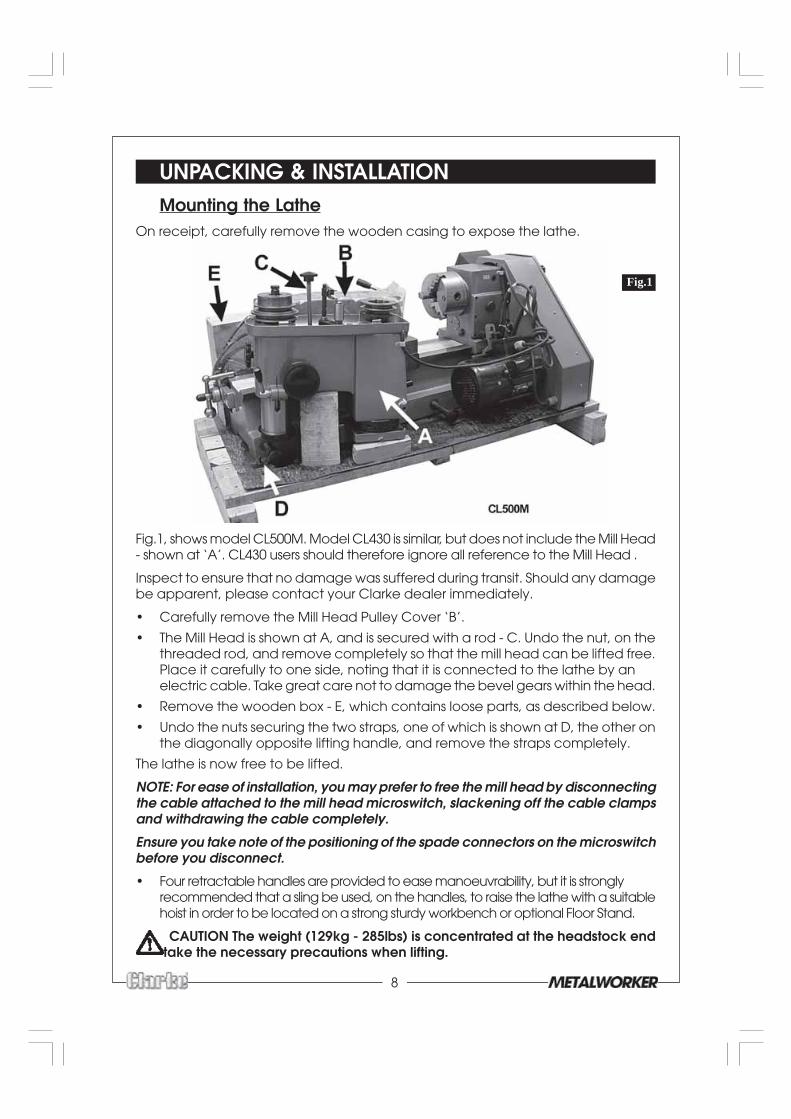
UNPACKING & INSTALLATIONMounting the Lathe
On receipt, carefully remove the wooden casing to expose the lathe.
Fig.1, shows model CL500M. Model CL430 is similar, but does not include the Mill Head- shown at ‘A’. CL430 users should therefore ignore all reference to the Mill Head .
Inspect to ensure that no damage was suffered during transit. Should any damagebe apparent, please contact your Clarke dealer immediately.
• Carefully remove the Mill Head Pulley Cover ‘B’.
• The Mill Head is shown at A, and is secured with a rod - C. Undo the nut, on thethreaded rod, and remove completely so that the mill head can be lifted free.Place it carefully to one side, noting that it is connected to the lathe by anelectric cable. Take great care not to damage the bevel gears within the head.
• Remove the wooden box - E, which contains loose parts, as described below.
• Undo the nuts securing the two straps, one of which is shown at D, the other onthe diagonally opposite lifting handle, and remove the straps completely.
The lathe is now free to be lifted.
NOTE: For ease of installation, you may prefer to free the mill head by disconnectingthe cable attached to the mill head microswitch, slackening off the cable clampsand withdrawing the cable completely.
Ensure you take note of the positioning of the spade connectors on the microswitchbefore you disconnect.
• Four retractable handles are provided to ease manoeuvrability, but it is stronglyrecommended that a sling be used, on the handles, to raise the lathe with a suitablehoist in order to be located on a strong sturdy workbench or optional Floor Stand.
CAUTION The weight (129kg - 285lbs) is concentrated at the headstock end- take the necessary precautions when lifting.
9
• Four holes are provided in the bed, for mounting purposes. Use suitable M10 bolts(not supplied) with flat washers, ensuring they are tight. At the leadscrew side ofthe bed, it will be necessary to thread the mounting bolts up through the bedthen screw on the washers and nuts.
NOTES: Ensure the location is adequately lit and that you will not be working in yourown shadow. Ensure an adequate power supply is close at hand. DO NOT allow cablesto trail on a workshop floor. Ensure there is adequate room for safe working.An optional floor stand complete with drip tray, specially designed for this product,is available from your CLARKE dealer. Bolt the lathe to the stand ensuring bolts arefully tightened. If the stand is not used, then the lathe should be mounted on a strong,heavy workbench, of sufficient height so that you do not need to bend your back toperform normal operations.The lathe should be at a suitable height so that the operator does not need tobend forward when operating. It should also be perfectly level and flat, using shimswhere necessary to ensure it is. Do not tighten bolts if the lathe is not sitting flat onits mounting surface, as this will tend to twist the bed.When the lathe is secure, proceed to remove all traces of preservative with paraffinor white spirits and lightly oil all machined surfaces.
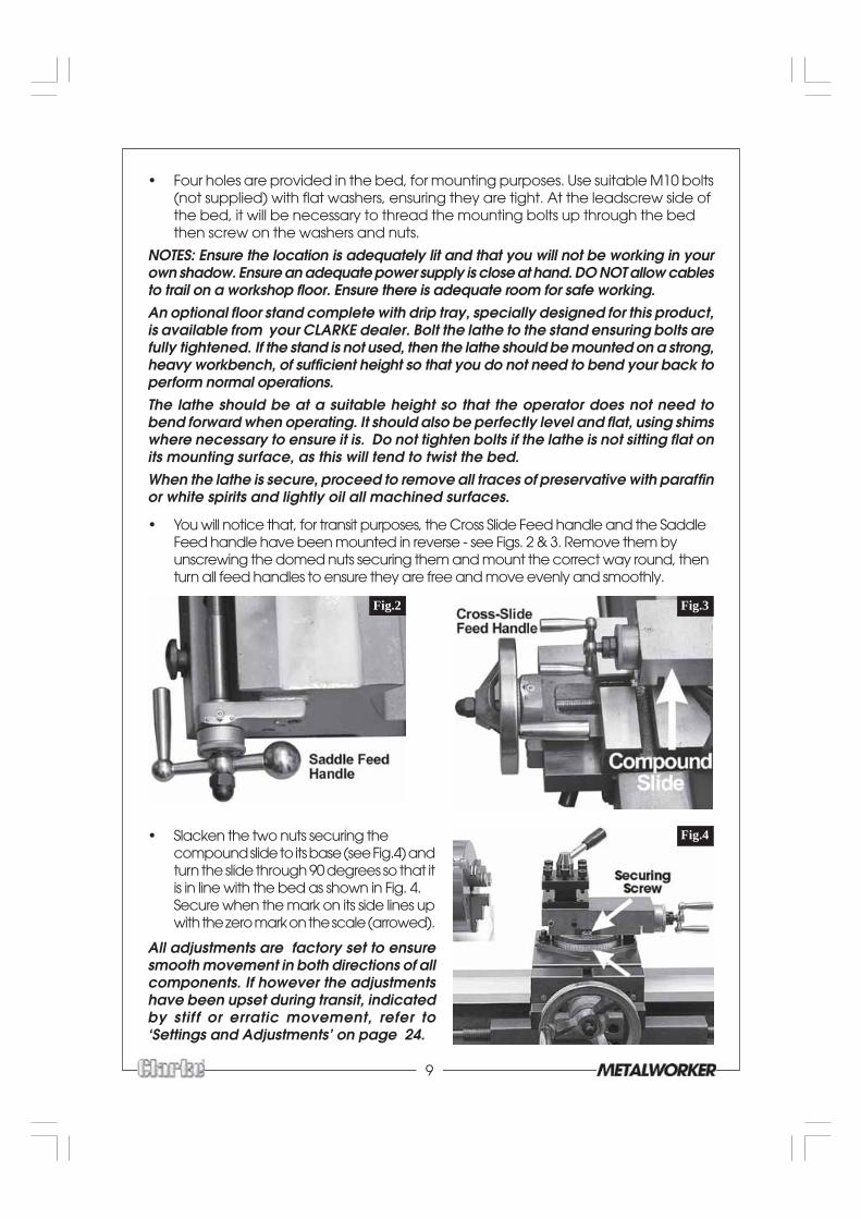
• You will notice that, for transit purposes, the Cross Slide Feed handle and the SaddleFeed handle have been mounted in reverse - see Figs. 2 & 3. Remove them byunscrewing the domed nuts securing them and mount the correct way round, thenturn all feed handles to ensure they are free and move evenly and smoothly.
• Slacken the two nuts securing thecompound slide to its base (see Fig.4) andturn the slide through 90 degrees so that itis in line with the bed as shown in Fig. 4.Secure when the mark on its side lines upwith the zero mark on the scale (arrowed).
All adjustments are factory set to ensuresmooth movement in both directions of allcomponents. If however the adjustmentshave been upset during transit, indicatedby stif f or erratic movement, refer to‘Settings and Adjustments’ on page 24.
Fig.2 Fig.3
Fig.4
10
Mounting the Mill HeadRemove the protective greased paper from the headstock mounting, and ensurethe surface is clean and undamaged.
• Carefully raise the Mill Head, noting that the plastic lower pulley cover is not fullysecured at this stage and is vulnerable. Very carefully lower the head on to itsmounting on the headstock. Secure with the four Hex socket head screws provided.
• If the cable to the microswitch has been disconnected, it should now bereplaced and the cable secured in the clamps on the side of the mill head.
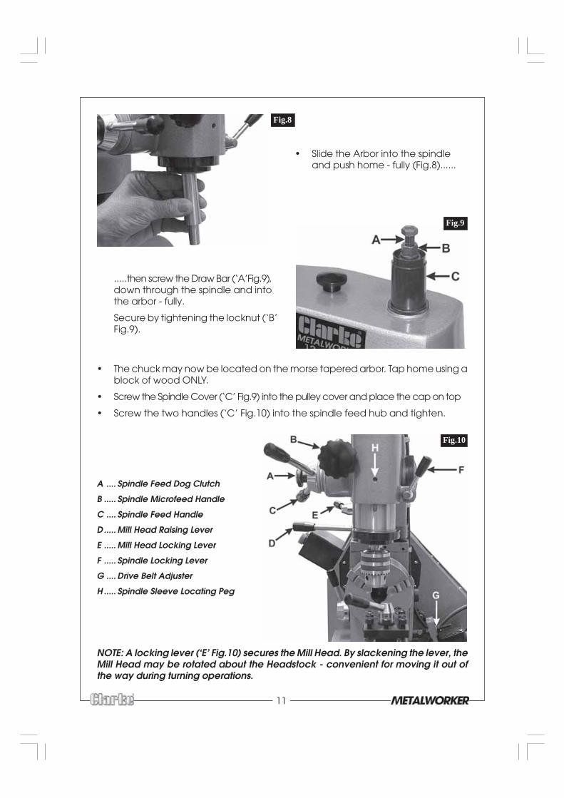
• You will note that cable is secured with a clamp plate, adjacent to the pulley. similar clamp is provided in the box of loose parts, and this should be screwedin place adjacent to the Driven Pulley so that the lower pulley cover is properly
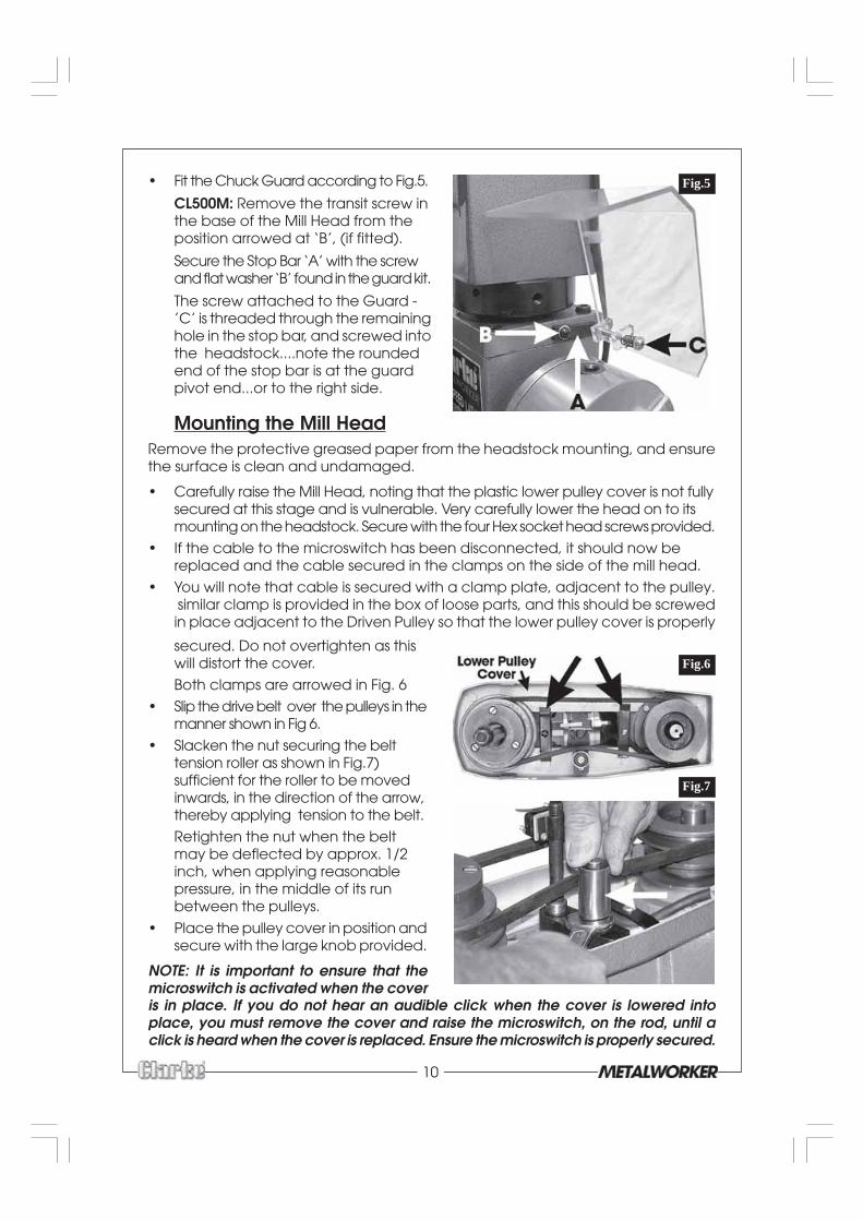
• Fit the Chuck Guard according to Fig.5.
CL500M: Remove the transit screw inthe base of the Mill Head from theposition arrowed at ‘B’, (if fitted).
Secure the Stop Bar ‘A’ with the screwand flat washer ‘B’ found in the guard kit.
The screw attached to the Guard -’C’ is threaded through the remaininghole in the stop bar, and screwed intothe headstock....note the roundedend of the stop bar is at the guardpivot end...or to the right side.
secured. Do not overtighten as thiswill distort the cover.
Both clamps are arrowed in Fig. 6
• Slip the drive belt over the pulleys in themanner shown in Fig 6.
• Slacken the nut securing the belttension roller as shown in Fig.7)sufficient for the roller to be movedinwards, in the direction of the arrow,thereby applying tension to the belt.
Retighten the nut when the beltmay be deflected by approx. 1/2inch, when applying reasonablepressure, in the middle of its runbetween the pulleys.
• Place the pulley cover in position andsecure with the large knob provided.
NOTE: It is important to ensure that themicroswitch is activated when the cover
Fig.7
Fig.5
is in place. If you do not hear an audible click when the cover is lowered intoplace, you must remove the cover and raise the microswitch, on the rod, until aclick is heard when the cover is replaced. Ensure the microswitch is properly secured.
Fig.6
11
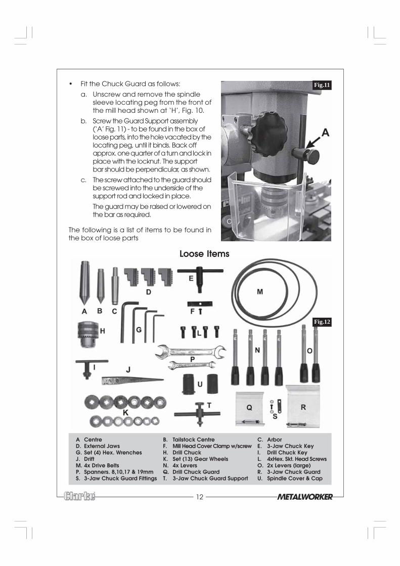
.....then screw the Draw Bar (‘A’Fig.9),down through the spindle and intothe arbor - fully.
Secure by tightening the locknut (‘B’Fig.9).
• The chuck may now be located on the morse tapered arbor. Tap home using ablock of wood ONLY.
• Screw the Spindle Cover (‘C’ Fig.9) into the pulley cover and place the cap on top
• Screw the two handles (‘C’ Fig.10) into the spindle feed hub and tighten.
NOTE: A locking lever (‘E’ Fig.10) secures the Mill Head. By slackening the lever, theMill Head may be rotated about the Headstock - convenient for moving it out ofthe way during turning operations.
Fig.9
Fig.10
A .... Spindle Feed Dog Clutch
B ..... Spindle Microfeed Handle
C .... Spindle Feed Handle
D ..... Mill Head Raising Lever
E ..... Mill Head Locking Lever
F ..... Spindle Locking Lever
G .... Drive Belt Adjuster
H ..... Spindle Sleeve Locating Peg
Fig.8
• Slide the Arbor into the spindleand push home - fully (Fig.8)......
12
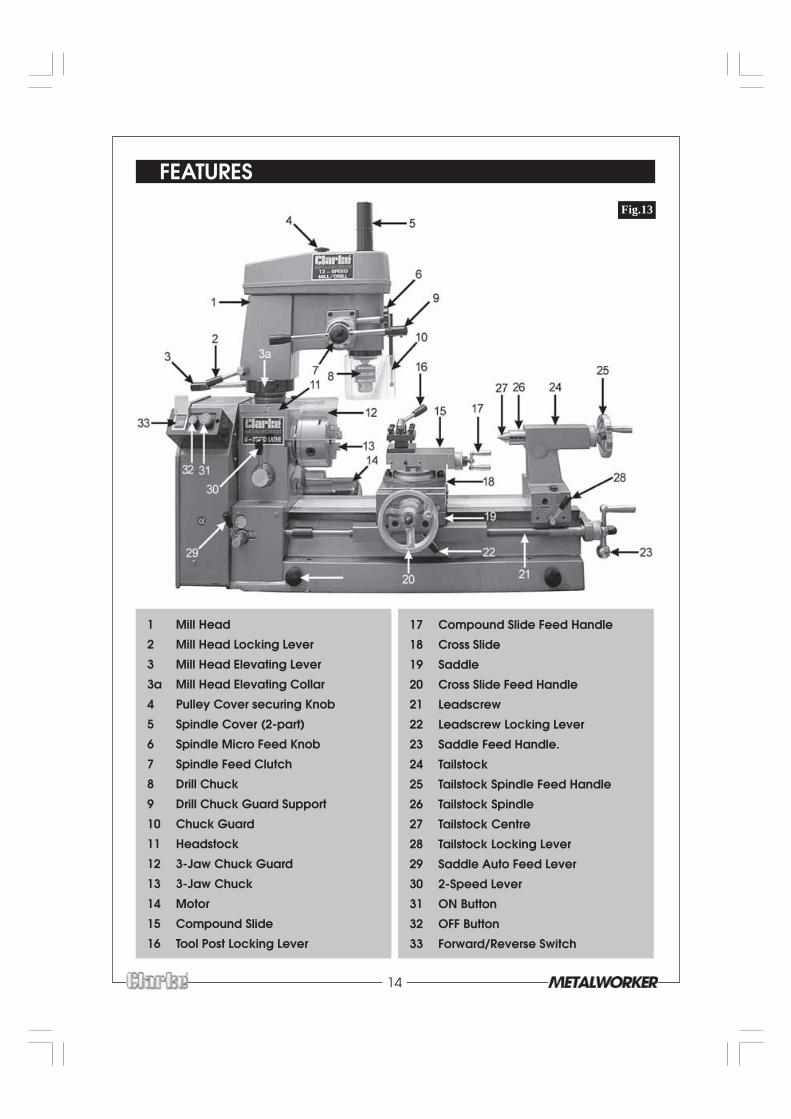
• Fit the Chuck Guard as follows:
a. Unscrew and remove the spindlesleeve locating peg from the front ofthe mill head shown at ‘H’, Fig. 10.
b. Screw the Guard Support assembly(‘A’ Fig. 11) - to be found in the box ofloose parts, into the hole vacated by thelocating peg, until it binds. Back offapprox. one quarter of a turn and lock inplace with the locknut. The supportbar should be perpendicular, as shown.
c. The screw attached to the guard shouldbe screwed into the underside of thesupport rod and locked in place.
The guard may be raised or lowered onthe bar as required.
The following is a list of items to be found inthe box of loose parts
Fig.11
Loose Items
Fig.12
A Centre B. Tailstock Centre C. ArborD. External Jaws F. Mill Head Cover Clamp w/screw E. 3-Jaw Chuck KeyG. Set (4) Hex. Wrenches H. Drill Chuck I. Drill Chuck KeyJ. Drift K. Set (13) Gear Wheels L. 4xHex. Skt. Head ScrewsM. 4x Drive Belts N. 4x Levers O. 2x Levers (large)P. Spanners. 8,10,17 & 19mm Q. Drill Chuck Guard R. 3-Jaw Chuck GuardS. 3-Jaw Chuck Guard Fittings T. 3-Jaw Chuck Guard Support U. Spindle Cover & Cap

13
ELECTRICAL CONNECTIONS
CAUTION!
DO NOT ATTEMPT TO USE THE MACHINE UNTIL INSTALLATION IS COMPLETED, AND ALLPRELIMINARY CHECKS HAVE BEEN MADE IN ACCORDANCE WITH THIS MANUAL.
Connect the mains lead to a standard, 230 Volt (50Hz) electrical supply through anapproved 13 amp BS 1363 plug, or a suitably fused isolator switch.
WARNING! THIS APPLIANCE MUST BE EARTHED
IMPORTANT: The wires in the mains lead are coloured in accordance with thefollowing code:
Green & Yellow - Earth
Blue - Neutral
Brown - Live
As the colours of the flexible lead of this appliance may not correspond with thecoloured markings identifying terminals in your plug proceed as follows:
• Connect GREEN & YELLOW coloured cord to plug terminal marked with aletter “E” or Earth symbol “ ” or coloured GREEN or GREEN & YELLOW.
• Connect BROWN cord to plug terminal marked with a letter “L” or coloured RED.
• Connect BLUE cord to plug terminal marked with a letter “N” or coloured BLACK.
If this appliance is fitted with a plug which is moulded onto the electric cable (i.e.non-wireable) please note:
1. The plug must be thrown away if it is cut from the electric cable. There is adanger of electric shock if it is subsequently inserted into a socket outlet.
2. Never use the plug without the fuse cover fitted.
3. Should you wish to replace a detachable fuse carrier, ensure that the correctreplacement is used (as indicated by marking or colour code).
4. Replacement fuse covers can be obtained from your local dealer or mostelectrical stockists.
5. The fuse in the plug must be replaced with one of the same rating (13amps)and this replacement must be ASTA approved to BS1362.
The Lathe, with Mill Head, is now ready for use, but before proceeding, it isstrongly advised that operators familiarise themselves with all controls,
methods of operation, and the machines limitations. These are describedin the following chapters.
14
FEATURES
Fig.13
1 Mill Head
2 Mill Head Locking Lever
3 Mill Head Elevating Lever
3a Mill Head Elevating Collar
4 Pulley Cover securing Knob
5 Spindle Cover (2-part)
6 Spindle Micro Feed Knob
7 Spindle Feed Clutch
8 Drill Chuck
9 Drill Chuck Guard Support
10 Chuck Guard
11 Headstock
12 3-Jaw Chuck Guard
13 3-Jaw Chuck
14 Motor
15 Compound Slide
16 Tool Post Locking Lever
17 Compound Slide Feed Handle
18 Cross Slide
19 Saddle
20 Cross Slide Feed Handle
21 Leadscrew
22 Leadscrew Locking Lever
23 Saddle Feed Handle.
24 Tailstock
25 Tailstock Spindle Feed Handle
26 Tailstock Spindle
27 Tailstock Centre
28 Tailstock Locking Lever
29 Saddle Auto Feed Lever
30 2-Speed Lever
31 ON Button
32 OFF Button
33 Forward/Reverse Switch
15
THE HEADSTOCKThe Motor drives the spindle via drive belts, which may be configured to provide 6 speeds.
A three jaw self centering chuck is fitted, and may be removed by unscrewing thethree bolts securing it to the spindle flange, so that optional accessories may beused, such as a Face Plate for use with the MT4 Centre provided, or an independent4-Jaw chuck.
Three external jaws are supplied to extend the capacity of the 3-jaw chuck. Themethod of assembly is described on page 25.
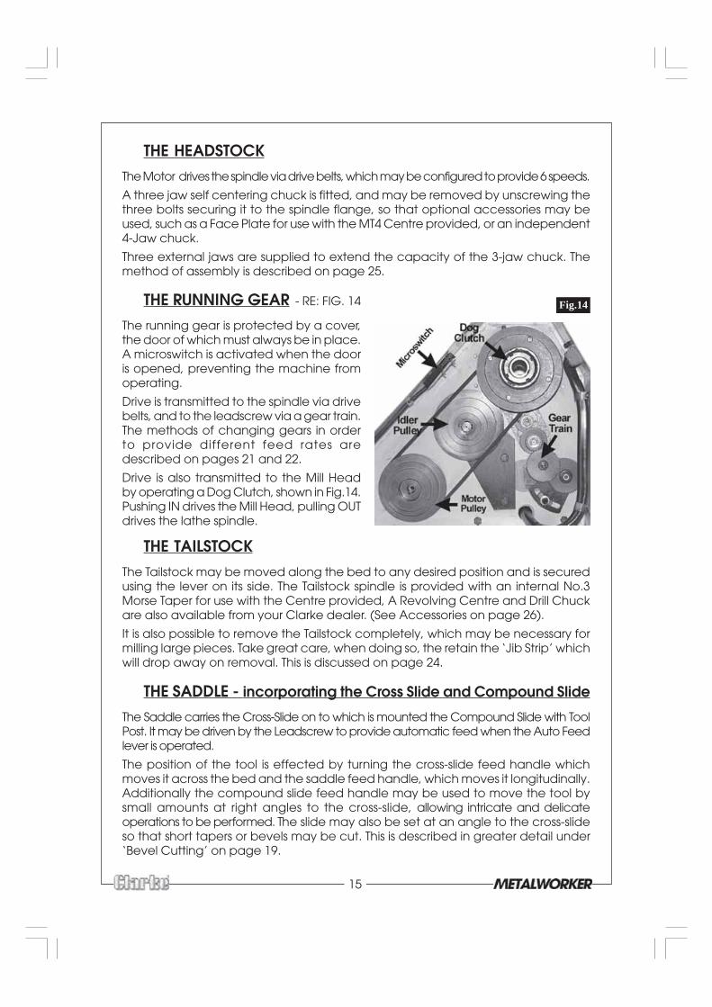
THE RUNNING GEAR - RE: FIG. 14
The running gear is protected by a cover,the door of which must always be in place.A microswitch is activated when the dooris opened, preventing the machine fromoperating.
Drive is transmitted to the spindle via drivebelts, and to the leadscrew via a gear train.The methods of changing gears in orderto provide different feed rates aredescribed on pages 21 and 22.
Drive is also transmitted to the Mill Headby operating a Dog Clutch, shown in Fig.14.Pushing IN drives the Mill Head, pulling OUTdrives the lathe spindle.
THE TAILSTOCKThe Tailstock may be moved along the bed to any desired position and is securedusing the lever on its side. The Tailstock spindle is provided with an internal No.3Morse Taper for use with the Centre provided, A Revolving Centre and Drill Chuckare also available from your Clarke dealer. (See Accessories on page 26).
It is also possible to remove the Tailstock completely, which may be necessary formilling large pieces. Take great care, when doing so, the retain the ‘Jib Strip’ whichwill drop away on removal. This is discussed on page 24.
THE SADDLE - incorporating the Cross Slide and Compound Slide
The Saddle carries the Cross-Slide on to which is mounted the Compound Slide with ToolPost. It may be driven by the Leadscrew to provide automatic feed when the Auto Feedlever is operated.
The position of the tool is effected by turning the cross-slide feed handle whichmoves it across the bed and the saddle feed handle, which moves it longitudinally.Additionally the compound slide feed handle may be used to move the tool bysmall amounts at right angles to the cross-slide, allowing intricate and delicateoperations to be performed. The slide may also be set at an angle to the cross-slideso that short tapers or bevels may be cut. This is described in greater detail under‘Bevel Cutting’ on page 19.
Fig.14

16
The cross-slide and compound slide feeds are provided with a scale. These areused to move the tool by precise amounts - one division being equivalent to 0.001”(0.025mm). As the feed handle is turned, so does the scale. The scale on the cross-slide feed may also be held stationary whilst the handle is turned, allowing thescale to be ‘zeroed’. The manner in which this is put to use is discussed in greaterdetail under ‘Operation’.
The tool post carries 8 hex socket head screws which are used to secure a cuttingtool in any desired position. Four may be mounted for convenience and to speedup your operation.
The tool post is rotated by slackening the lever on its top, sufficient for the post tobe lifted slightly and then turned to the desired position.
ALWAYS ensure the post, and hence the tool, is secured by screwing down thelever firmly before attempting to cut.
The Compound Slide may be removed completely so that a workpiece may bebolted to the machined surface of the Cross Slide, for milling purposes, using the ‘T’slots provided. A 12 piece T-nut and bolt set is available from your CLARKE dealer.Alternatively, a Vice (supplied) may be bolted to the Cross Slide, using the T-slots, inorder to secure a workpiece.
The saddle may be locked in place, using the Leadscrew Locking lever, 22 Fig.13.
This is useful when facing or cutting tapers, where the cross slide or compound slideonly, is used. Under these conditions, care must be taken to ensure the saddleauto feed lever is disengaged.
THE MILL HEAD (Re: Fig 13)
The Mill Head spindle is driven when the dog clutch, within the running gear, (seeFig.16) is pushed INWARDS. 6 Speeds are available from the pulley system, which isincreased to 12 via a 2-speed pulley system, mounted on top of the Mill Head. Thepulley cover must always be in place and the microswitch, within, MUST operatewhen the cover is lowered, otherwise it will not be possible to operate the machine.
The complete Mill Head assembly may be rotated about the Headstock byslackening the locking lever - 2. Take care when rotating to ensure the 3-jaw chuckguard is fully lowered, otherwise damage to it could occur.
Additionally, the head assembly may be raised, to increase its capacity, by turningthe Elevating Collar - 3a, clockwise, (it will be tight to begin with), using the leversprovided. When lowering, simply turn the collar anticlockwise whilst pressing downon the head.
The spindle is provided with an internal No.3 Morse taper. An Arbor is supplied foruse with the Drill Chuck (also supplied), or Mill Chucks and other accessories availablefrom your Clarke dealer (see Accessories).
Spindle feed is controlled using either the feed levers or the micro feed knob. Aclutch -7, on the spindle feed hub, when pushed fully inwards engages the drive tothe micro feed knob. When pulled outwards, drive is transmitted to the feed handles.
NOTE: As the clutch may be tight, It may be necessary to ‘jiggle’ the feed levers inorder to pull OUT or push IN the clutch.The Chuck Guard must always be in place when the Mill Head is in use, positionedso as to provide maximum protection against flying swarf.
17
PREPARATION FOR USE
A. SIMPLE TURNINGThe following notes are guidelines as to how to set up the lathe in order to carry outa simple turning operation.
ALWAYS plan your work. Have drawings or a plan on hand together with anymeasuring instruments you may require, such as micrometers/verniers/callipers etc.
1. Set Spindle speed
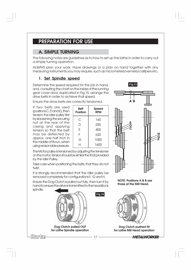
Determine the speed required for the job in hand,and, consulting the chart on the inside of the runninggear cover door, duplicated in Fig.15, arrange thedrive belts in order to achieve that speed.
Ensure the drive belts are correctly tensioned.
Fig.15
C 160
D 250
E 400
F 630
G 1000
H 1600
BeltPosition
SpeedRPM
NOTE: Positions A & B arethose at the Mill Head.
If two belts are used(positions C, D and E), thentension the Idler pulley firstby slackening the securingnut at the rear of thecasing and applyingtension so that the beltmay be deflected byapprox. one half inch inthe middle of its run, whenusing reasonable pressure.
The Motor pulley is tensioned by adjusting the tensioneron the motor. Tension should be similar the that providedby the Idler Pulley.
Take care when positioning the belts, that they do nottwist.
It is strongly recommended that the Idler pulley beremoved completely for configurations F, G and H.
Ensure the Dog Clutch is pulled out fully, then turn it byhand to ensure the drive is transmitted to the headstockspindle.
Fig.16
Dog Clutch pulled OUTfor Lathe Spindle operation
Dog Clutch pushed INfor Lathe Mill Head operation
18
2. Mount the Cutting Tool
Select a cutting tool that will produce the desired cut and mount it in the ToolRest, with as little overhang as possible, securing it using three hex socket headscrews. (Ideally, the overhang should be approx. 10 mm but not more than15mm for a straight tool).
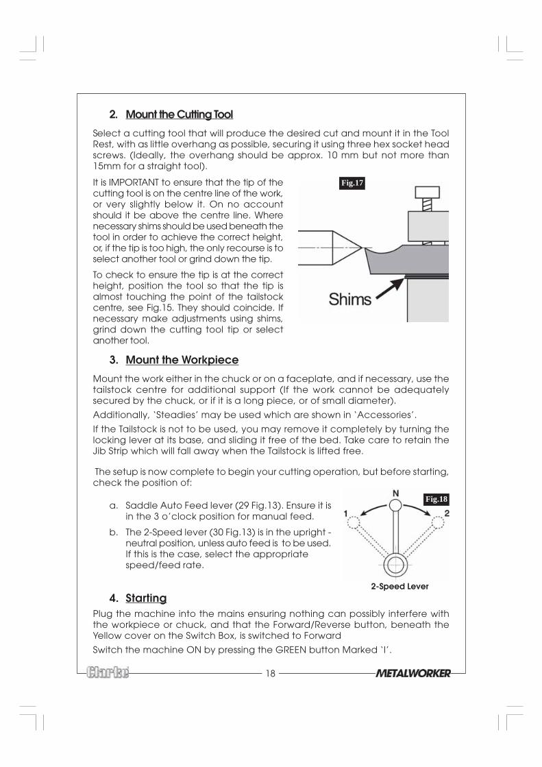
It is IMPORTANT to ensure that the tip of thecutting tool is on the centre line of the work,or very slightly below it. On no accountshould it be above the centre line. Wherenecessary shims should be used beneath thetool in order to achieve the correct height,or, if the tip is too high, the only recourse is toselect another tool or grind down the tip.
To check to ensure the tip is at the correctheight, position the tool so that the tip isalmost touching the point of the tailstockcentre, see Fig.15. They should coincide. Ifnecessary make adjustments using shims,grind down the cutting tool tip or selectanother tool.
3. Mount the Workpiece
Mount the work either in the chuck or on a faceplate, and if necessary, use thetailstock centre for additional support (If the work cannot be adequatelysecured by the chuck, or if it is a long piece, or of small diameter).
Additionally, ‘Steadies’ may be used which are shown in ‘Accessories’.
If the Tailstock is not to be used, you may remove it completely by turning thelocking lever at its base, and sliding it free of the bed. Take care to retain theJib Strip which will fall away when the Tailstock is lifted free.
The setup is now complete to begin your cutting operation, but before starting,check the position of:
Fig.17
a. Saddle Auto Feed lever (29 Fig.13). Ensure it isin the 3 o’clock position for manual feed.
b. The 2-Speed lever (30 Fig.13) is in the upright -neutral position, unless auto feed is to be used.If this is the case, select the appropriatespeed/feed rate.
2-Speed Lever4. Starting
Plug the machine into the mains ensuring nothing can possibly interfere withthe workpiece or chuck, and that the Forward/Reverse button, beneath theYellow cover on the Switch Box, is switched to Forward
Switch the machine ON by pressing the GREEN button Marked ‘I’.
Fig.18

19
B. SIMPLE TURNING WITH POWER FEEDThe same basic setup is used as for simple turning, except that, before starting,the 2-Speed Lever is set to either 1 or 2 in order to provide the desired feed rate.
CAUTION: NEVER attempt to change speeds whilst the machine is operating.
As mentioned previously, the rotational speed of the leadscrew, and hencethe rate of feed of the tool, is dependant upon the gear train configuration.
The feed rate for normal turning is considerably less than that used for screwcutting. The lathe is factory configured for normal turning, however, if you havebeen screw cutting, always remember to reset the gear configuration to thatfor normal turning. Please refer to the chart on page 21 which shows the gearconfigurations, together with an explanation of how to change gears.
1. With the cutting tool at right angles to the workpiece, wind the cross-slideso that the cutting tool tip JUST touches the work surface.
2. Hold the cross-slide handle still whilst turning the scale so that it registerszero, then, using the saddle feed handle. Move the cutting tool so that it issomewhere to the right of the work
3. Advance the cutting tool, using the cross-slide handle, the requisite number ofgraduations to produce the desired depth of cut. 1 graduation = 0.001 inches.
4. Taking all precautions previously mentioned and ensuring there are nopotential obstacles to the rotating workpiece, switch the machine ON
5. Engage the auto feed by moving the lever towards the 12 o’clock position.At this point the cutting tool will begin its travel towards the chuck - beready to disengage the auto feed quickly by knocking the lever firmly tothe 3 o’clock position.
NOTE: Always stop short of an intended shoulder - which should always be finishedmanually, by switching the machine OFF. If you require a shoulder with perfectlyclean corners, then you need to use an appropriately shaped tool.
6. Retract the tool by one or two complete turns on the cross-slide feed, thenwind the saddle so that the tool is at the start point once again.
Advance the tool to its original position, using the scale, then advance itfurther by the required depth of cut. When ready, re-engage the auto feedand proceed to take another cut.
NOTE: You may notice considerable backlash on the screw threads, this is quitenormal and should not cause alarm.
C. BEVEL CUTTING Re: Fig. 19
Bevel cutting involves the use of the compound slide, which is mounted on thecross-slide and set at right angles to it for all normal cutting operations. This isindicated by the zero mark, on the scale, lining up with the mark etched on thebody of the cross-slide.
To set the compound slide so that the cutting tool will cut a bevel, slacken thetwo screws, securing the compound slide to the cross slide, sufficient to allowthe compound slide to be turned to the desired angle, as indicated on thescale. Secure the slide in this position by re-tightening the securing screws.

20
Fig.19The taper, or bevel, is cut by setting the crossslide appropriately then using the compoundslide feed handle to advance the cutting toolin the direction of the arrow as shown in Fig.18.
D. SCREW CUTTINGThis operation requires a degree of skill andaccuracy, and should not be attemptedunless you are completely familiar with allaspects of the lathe.
Essentially, the saddle will move towards theheadstock under power, the same ascutting using auto feed, except the rate offeed is greater, as determined by the gearconfiguration. The cutting tool therefore, ismoving ever closer to the rotating chuck.Great care and concentration must be exercised therefore, to ensure that the twodo not meet when the machine is operating, as this could be disastrous.
Imperial Threads in a range from 11 to 40 threads per inch, and Metric threads witha pitch of 0.5 to 3mm may be cut. It is important to remember that the type ofthread you need to cut, i.e. Metric, UNF, BA, BSP, BSW etc., will be totally dependantupon the cutting tool profile, as profiles differ from thread to thread. .
For detailed information regarding screw cutting techniques, cutting tools etc.,you should consult a suitable handbook or obtain advice from a qualified person.
The general procedure for screw cutting is as follows:
1. Try to get as much distance from the chuck to the end of the proposed screwthread as possible, and if your design allows, cut a ‘run-off’ into the work whichis of a smaller diameter than the root diameter of the proposed screw thread.
NOTE: that for long threads it may be necessary to use steadies.2. Install the appropriate gears for the thread required, and correctly mount the
cutting tool. Set your required depth of cut, in the same manner as that fornormal turning, and position the tool well to the right of the workpiece.
NOTE: Depth of cut is vitally important and may be calculated or obtained from anappropriate reference manual. Bear in mind that more than one pass may be necessary3. Taking all necessary precautions previously stated, and ensuring the FORWARD/
REVERSE switch is in the FORWARD position, start the machine with the powerfeed lever in its’ disengaged (3 o’clock) position.
4. When ready, engage the power feed and prepare to switch OFF the machineas the cutting tool approaches the end of the intended screw thread.
When the machine has stopped, continue to wind the tool forward by turningthe chuck by hand to complete the thread.
5. Switch the FORWARD/REVERSE switch to REVERSE and switch ON the lathe. Thecutting tool will move back towards the start point. DO NOT TOUCH THECROSS-SLIDE HANDLE. Switch OFF again at the end of the thread.
6. Switch back to FORWARD, increase the depth of cut, as required, then switchON again to take another cut.
21
CHANGING GEARS FOR SCREW CUTTINGThe leadscrew is driven via a gear train, The gear ratio will therefore determine therotational speed of the leadscrew with relation to the spindle. i.e. one turn of thespindle will turn the leadscrew an amount determined by the gear ratio.
By setting the gears to a known ratio, we can therefore produce threads to a known size.
As previously mentioned, the actual thread produced will be totally dependantupon the profile of the cutting tool. It is not within the scope of this manual toprovide detailed information regarding types of cutting tool, cutting speeds andworking with various types of material etc., and it is strongly advised that you consultappropriate handbooks or seek advice from a qualified person.
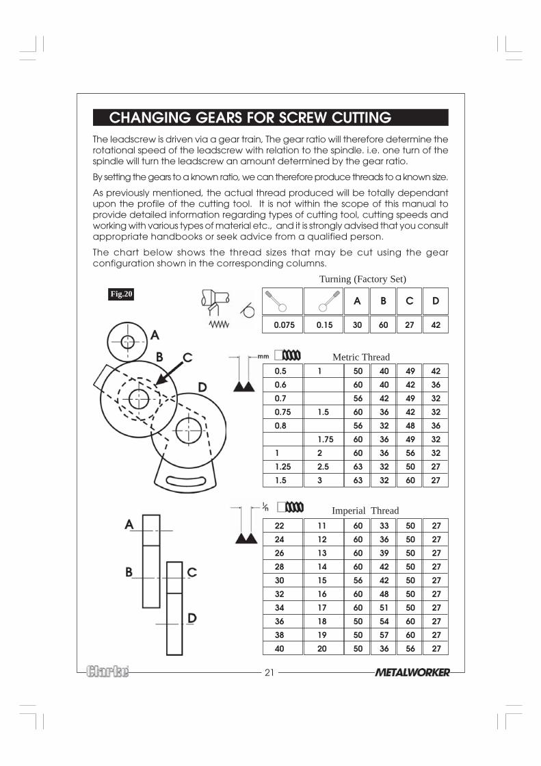
The chart below shows the thread sizes that may be cut using the gearconfiguration shown in the corresponding columns.
0.5 1 50 40 49 42
0.6 60 40 42 36
0.7 56 42 49 32
0.75 1.5 60 36 42 32
0.8 56 32 48 36
1.75 60 36 49 32
1 2 60 36 56 32
1.25 2.5 63 32 50 27
1.5 3 63 32 60 27
22 11 60 33 50 27
24 12 60 36 50 27
26 13 60 39 50 27
28 14 60 42 50 27
30 15 56 42 50 27
32 16 60 48 50 27
34 17 60 51 50 27
36 18 50 54 60 27
38 19 50 57 60 27
40 20 50 36 56 27
A B C D
0.075 0.15 30 60 27 42
Metric Thread
Imperial Thread
Turning (Factory Set)
Fig.20

22
To cut 12 TPI, Imperial Thread, use 60T at position A,
36T at position B
50T at position C
27T at position D
In order to change the gears, ensure the machine is switched OFF and disconnectedfrom the mains supply.
Re: Fig. 21
Open the door to the gear train.
1. Unscrew the hex socket head screw - 6,allowing the gear train to drop so thatgear B becomes disengaged fromgear A - as shown.
2. To change gear A, remove thecirclip - 1 and pull off the gear.Replace ensuring the boss facestowards you.
3. To change gears C and B, removethe circlip -2 and pull off the gears.Replace ensuring the bosses - 5face towards you.
4. To change gear D, unscrew andremove the securing nut and pull offthe flat washer 3, distance piece 4,and the gear. Replace in reverseorder.
5. Re-engage gears A and B andtighten the Hex socket head screw- 6, ensuring a little backlash isevident between the gears.
Fig.21
Note: Backlash should be as little as possible without being over tight. (Turn thespindle by hand to test for backlash).6. Replace the door
NOTE: The machine will not run with the cover removed.
NOTE: Fig. 21 shows a gear configuration for simple turning.
A - 30 B - 60 C - 27 D - 63
23
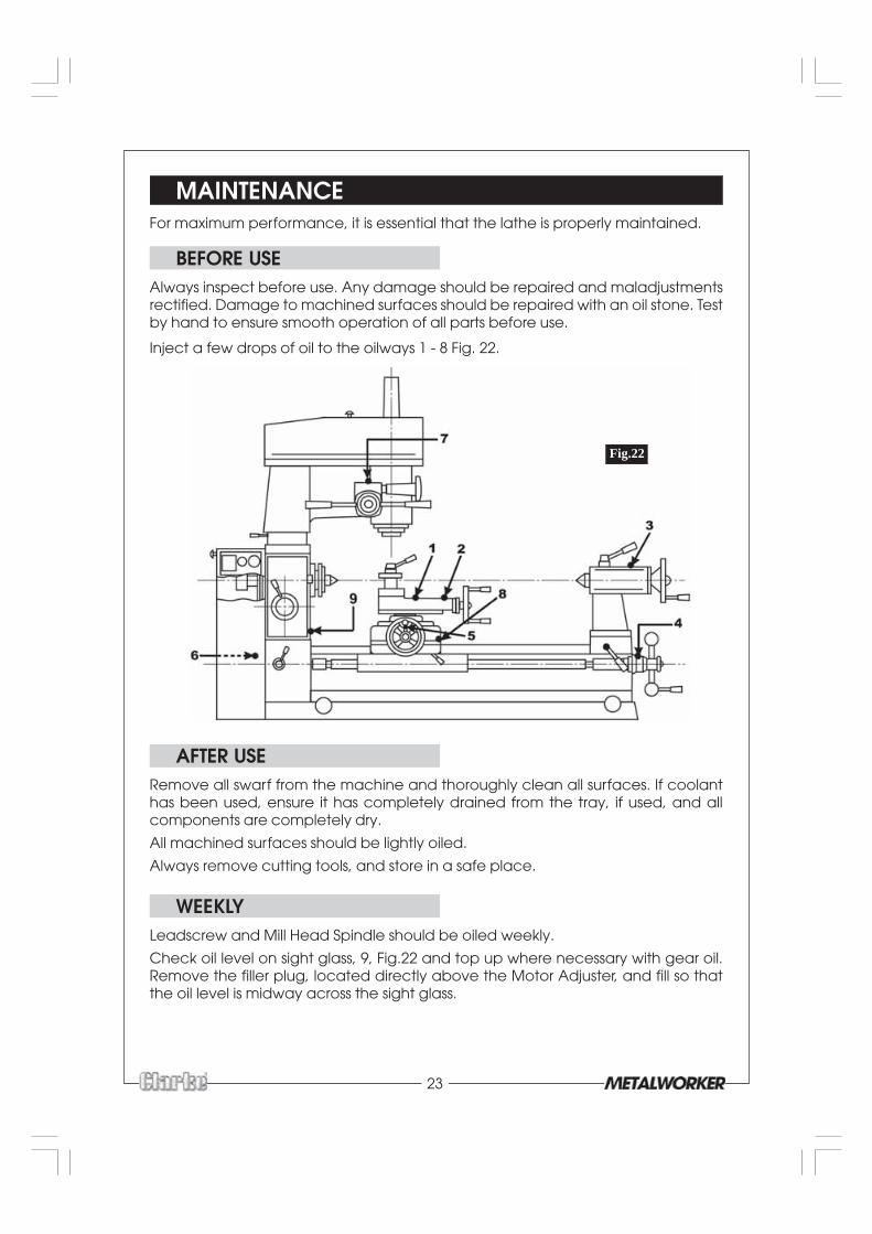
MAINTENANCEFor maximum performance, it is essential that the lathe is properly maintained.
BEFORE USEAlways inspect before use. Any damage should be repaired and maladjustmentsrectified. Damage to machined surfaces should be repaired with an oil stone. Testby hand to ensure smooth operation of all parts before use.
Inject a few drops of oil to the oilways 1 - 8 Fig. 22.
AFTER USERemove all swarf from the machine and thoroughly clean all surfaces. If coolanthas been used, ensure it has completely drained from the tray, if used, and allcomponents are completely dry.
All machined surfaces should be lightly oiled.
Always remove cutting tools, and store in a safe place.
WEEKLYLeadscrew and Mill Head Spindle should be oiled weekly.
Check oil level on sight glass, 9, Fig.22 and top up where necessary with gear oil.Remove the filler plug, located directly above the Motor Adjuster, and fill so thatthe oil level is midway across the sight glass.
Fig.22
24
SETTINGS AND ADJUSTMENTSOccasionally, it may be necessary to readjust various components in order to maintainoptimum performance. The adjustments that may be performed are as follows:
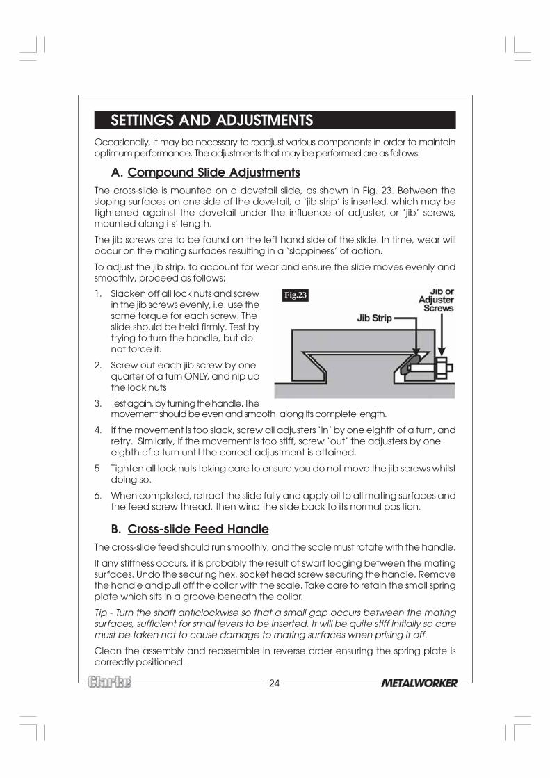
A. Compound Slide AdjustmentsThe cross-slide is mounted on a dovetail slide, as shown in Fig. 23. Between thesloping surfaces on one side of the dovetail, a ‘jib strip’ is inserted, which may betightened against the dovetail under the influence of adjuster, or ’jib’ screws,mounted along its’ length.
The jib screws are to be found on the left hand side of the slide. In time, wear willoccur on the mating surfaces resulting in a ‘sloppiness’ of action.
To adjust the jib strip, to account for wear and ensure the slide moves evenly andsmoothly, proceed as follows:
1. Slacken off all lock nuts and screwin the jib screws evenly, i.e. use thesame torque for each screw. Theslide should be held firmly. Test bytrying to turn the handle, but donot force it.
2. Screw out each jib screw by onequarter of a turn ONLY, and nip upthe lock nuts
3. Test again, by turning the handle. Themovement should be even and smooth along its complete length.
4. If the movement is too slack, screw all adjusters ‘in’ by one eighth of a turn, andretry. Similarly, if the movement is too stiff, screw ‘out’ the adjusters by oneeighth of a turn until the correct adjustment is attained.
5 Tighten all lock nuts taking care to ensure you do not move the jib screws whilstdoing so.
6. When completed, retract the slide fully and apply oil to all mating surfaces andthe feed screw thread, then wind the slide back to its normal position.
B. Cross-slide Feed HandleThe cross-slide feed should run smoothly, and the scale must rotate with the handle.
If any stiffness occurs, it is probably the result of swarf lodging between the matingsurfaces. Undo the securing hex. socket head screw securing the handle. Removethe handle and pull off the collar with the scale. Take care to retain the small springplate which sits in a groove beneath the collar.
Tip - Turn the shaft anticlockwise so that a small gap occurs between the matingsurfaces, sufficient for small levers to be inserted. It will be quite stiff initially so caremust be taken not to cause damage to mating surfaces when prising it off.
Clean the assembly and reassemble in reverse order ensuring the spring plate iscorrectly positioned.
Fig.23
25
C. Cross-slide AdjustmentsCross slide adjustments are made in the same way as those for the compoundslide. The jib screws however are hex socket head screws and are to be found onthe right hand side of the slide, i.e. facing the tailstock.
NOTE:It is important that the cross-slide and compound slide adjustments are correctly carriedout and that there is no ‘sloppiness’ of action. Any maladjustments will have a seriouseffect on the quality of your work, as they will all be transferred to the tool tip.It is vital that there is as little movement of the tool as possible.
D. Fitting External Jaws - 3-Jaw Chuck
To change the jaws, insert the chuck key and open the jaws to their fullest extent.It will then be possible to remove each jaw in turn.
Replace them with the external jaws, noting the following.
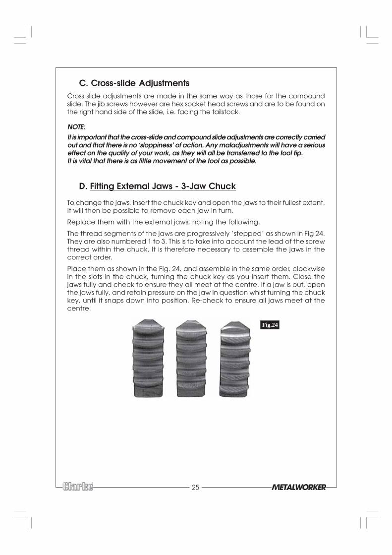
The thread segments of the jaws are progressively ‘stepped’ as shown in Fig 24.They are also numbered 1 to 3. This is to take into account the lead of the screwthread within the chuck. It is therefore necessary to assemble the jaws in thecorrect order.
Place them as shown in the Fig. 24, and assemble in the same order, clockwisein the slots in the chuck, turning the chuck key as you insert them. Close thejaws fully and check to ensure they all meet at the centre. If a jaw is out, openthe jaws fully, and retain pressure on the jaw in question whist turning the chuckkey, until it snaps down into position. Re-check to ensure all jaws meet at thecentre.
Fig.24
26
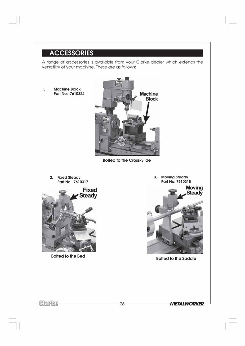
ACCESSORIESA range of accessories is available from your Clarke dealer which extends theversatility of your machine. These are as follows:
3. Moving SteadyPart No: 7610318
2. Fixed SteadyPart No: 7610317
1. Machine BlockPart No: 7610324
Bolted to the Bed Bolted to the Saddle
Bolted to the Cross-Slide
27
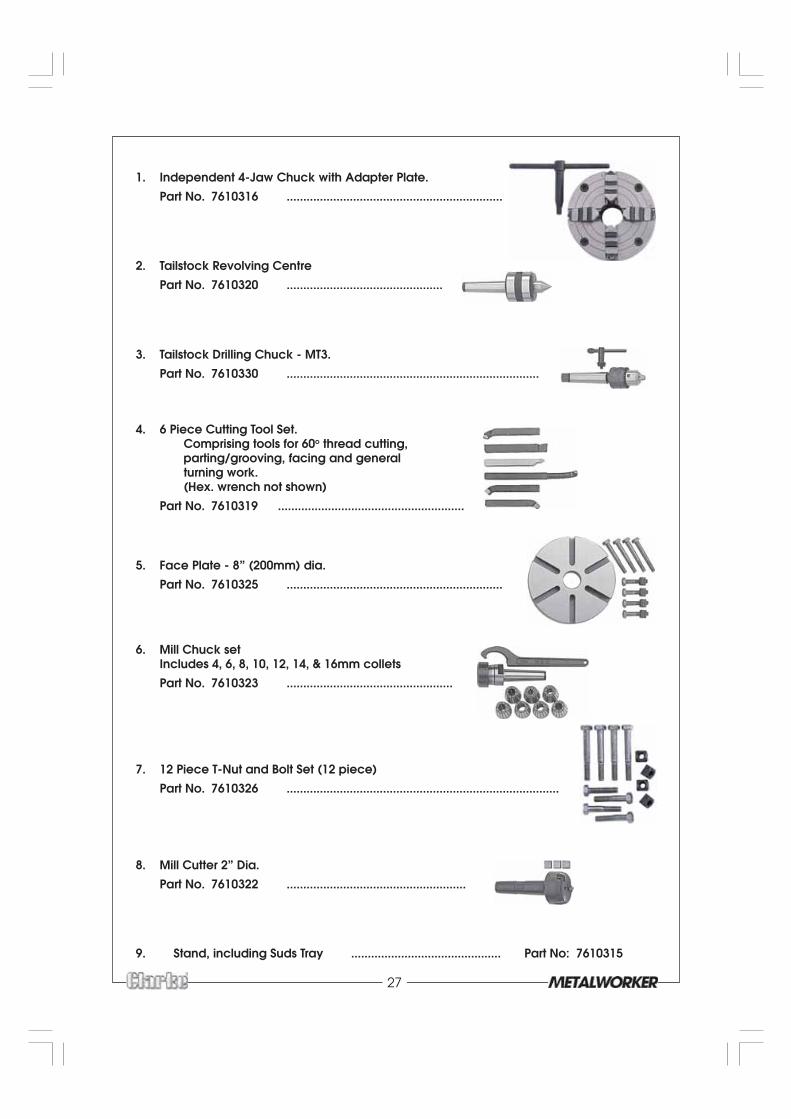
1. Independent 4-Jaw Chuck with Adapter Plate.
Part No. 7610316 .................................................................
2. Tailstock Revolving Centre
Part No. 7610320 ...............................................
3. Tailstock Drilling Chuck - MT3.
Part No. 7610330 ............................................................................
4. 6 Piece Cutting Tool Set.Comprising tools for 60o thread cutting,parting/grooving, facing and generalturning work.(Hex. wrench not shown)
Part No. 7610319 ........................................................
5. Face Plate - 8” (200mm) dia.
Part No. 7610325 .................................................................
6. Mill Chuck setIncludes 4, 6, 8, 10, 12, 14, & 16mm collets
Part No. 7610323 ..................................................
7. 12 Piece T-Nut and Bolt Set (12 piece)
Part No. 7610326 ..................................................................................
8. Mill Cutter 2” Dia.
Part No. 7610322 ......................................................
9. Stand, including Suds Tray ............................................. Part No: 7610315