Embed Size (px)
Citation preview

RD-H147 386 SAFETY EVALUATION OF AN ELECTRONIC TOTALIZER CONTAINING i/iA LI/(CF)X CELL(U) NAVAL SURFACE WEAPONS CENTER SILVERSPRING MD P B DAVIS ET AL. 01 NOV 83 NSkC/TR-B3-58
UNCLASSIFIED F/G 18/3 N
mmmmhmhhmmEIEEE".mmmm
L3.2
II DAI 122 /
!LI
- 11.8
1ff W5 11111=1411116 'a
NSWC TR 83-508
SAFETY EVALUATION OF AN ELECTRONICTOTALIZER CONTAINING A U/(CF)x CELL
BY P.B. DAVIS, R.F. BIS, J.A. BARNES,S. E. BUCHHOLZ, F.C. DEBOLD, L.A. KOWALCHIK
RESEARCH AND TECHNOLOGY DEPARTMENT
I NOVEMBER 1983
Approved for public reletase distribution unlimited.
NOV 9 1984,
UAsw A
*
NAVAL SURFACE WEAPONS CENTERDahigren, Virginia 2248 Silver Spring, Maryland 20910
84 11 05 091
U L - .... , -.
+- . . .-
UNCLASSIFIEDSECU.ITY CLASSIFICATION OF THIS PAGE (Wen Data Entered) _ _._.
REPORT DOCUMENTATION PAGE READ INSTRUCTIONSBEFORE COMPLETING FORM
I. REPORT NUMBER N2 OVAC N 3. IPIENT'S CATALOG NUMBER :2. GO T-~pk
NSWC TR 83-508
4. TITLE (and Subtitle) S. TYPE OF REPORT & PERIOD COVERED
SAFETY EVALUATION OF AN ELECTRONIC TOTALIZER.CONTAINING A Li/(CF)x CELL . PERFORMING ORG. REPORT NUMBER
7. APITHOR(s) 8. CONTRACT OR GRANT NUMBER(&)
P. B. Davis, J. A. Barnes, R. F. Bis,S. E. Buchholz, F. C. DeBold, L. A. Kowalchik
" 9. PERFORMING ORGANIZATION NAME AND ADDRESS 10. PROGRAM ELEMENT. PROJECT. TASK(AREA & WORK UNIT NUMBERS
Naval Surface Weapons Center (Code R33)
White Oak
Silver Spring, MD 2091011. CONTROLLING OFFICE NAME AND ADDRESS 12. REPORT DATE
1 November 198313. NUMBER OF PAGES
3314. MONITORING AGENCY NAME & ADDRESS(If different from Controlling Office) 15. SECURITY CLASS. (of this report)
UNCLASSIFIED
I~DECL ASSI FICATION/ DOWNGRADINGSCHEDULE
16. DISTRIBUTION STATEMENT (of this Report)
Approved for public release, distribution unlimited
17. DISTRIBUTION STATEMENT (of the abstract entored In Block 20, If different from Report)
1 SUPPLEMENTARY NOTES
19. KEY WORDS (Continue on reveree side it neceseary and Identify by block number)
Lithium Battery Safety forced discharge
Li/(CF)x Battery chargingElectronic Totalizer Poly-carbonmonofluoride
short circuitheating
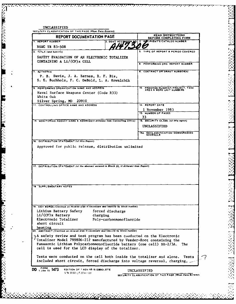
20. ABSTRACT (Continue on reverse aide Itf neceseary end Identify by block number)
IA safety review and test program has been conducted on the ElectronicTotalizer Model 799806-212 manufactured by Veeder-Root containing the
Panasonic Lithium Polycarbonmonofluoride battery (one cell) BR-2/3A. The
cell is used for the LCD display of the totalizer.
Tests were conducted on the cell both inside the totalizer and alone. Tests <7/included short circuit, forced discharge into voltage reversal, charging, .--.
DD IAN 73 1473 EDITION OF I NOV 35 IS OBSOLETE UNCLASSIFIEDS'N 012LF.014'.,1Oi
SECURITY CLASSIFICATION or THIS PAGE (When Date En-eord)
-:.% .. .. .!..
UNCLASSIFIEDSECURITY CLASSIFICATION OP THIS PAGE M'Ila, Di E tered)
'7heat tape, and gas sample collection of combustion products. The tests wererun on both fresh cells and partially discharged cells. The forced dischargeand charging tests were conducted at both the 25OmA and 1 amp level.
No fire or flame was noted during the tests with the exception of the heattape runs. During heat tape tests fire was noted at 450 7< -'
t.-P
S..~ r
*4%*
N'":
I.
UNCLASS IF IEDSECURITY CLASSIFICATION OF THIS PAGE(~hie, Dlil Mnte,.d)

NSWC TR 83-508
0 FOREWORD
Lithium Poly-Carbonsonofluoride (LI/(CF)x) batteries are used to provide
power for the Veeder-Root Electronic Totalizer. This report presents results
of a test program to determine if the system is safe for land-base use and to
characterize the overall safety of the Li/(CF)x cell. The work presented in
this report was sponsored by NAVELEX HQ Code PDE 110-142.
Approved by:
& fR. DIXON, HeadMaterials Division
cssion Paor
• ' Ju~ti i'
-
I), C TAB%p l>in-l~f~ 0
| : nounced
jut~tification---- -- -- -- - - -- --
Dj t r ibutio / ..Availability s
Dist Speciax
i/tiilii#
NSVC TR 83-508
CONENTS
Chpter pg
2 £XPERINNTAL.. ... ... eoe ..... ......... ........ oo*9*
3 RESULTS AND DISCUSSION..o ....... o................9
NSWC TR 83-508
ILLUSTRATIONS .,.'%
Figure Page .. .
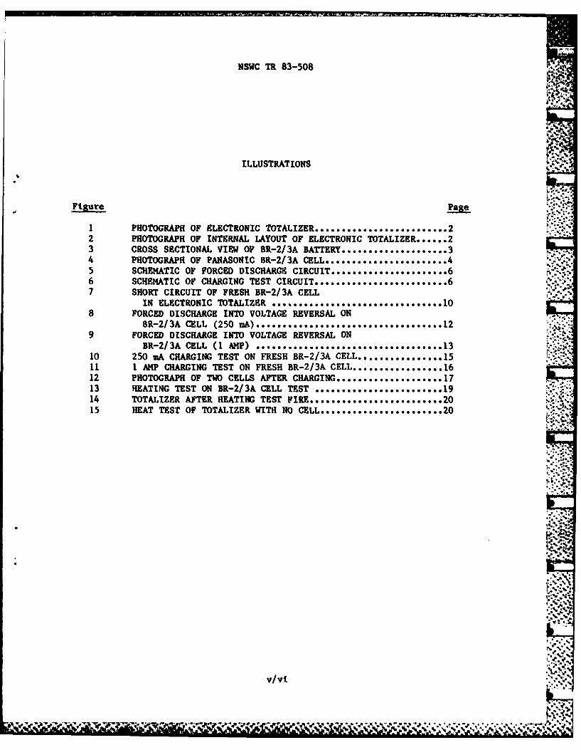
PHOTOGRAPH OF ELECTRONIC TOTALIZER........................22 PHOTOGRAPH OF INTERNAL LAYOUT OF ELECTRONIC TOTALIZER ...... 23 CROSS SECTIONAL VIEW OF BR-2/3A BATTERY .................... 34 PHOTOGRAPH OF PANASONIC BR-2/3A CELL ....................... 45 SCHEMATIC OF FORCED DISCHARGE CIRCUIT ..................... 66 SCHEMATIC OF CHARGING TEST CIRCUIT........................67 SHORT CIRCUIT OF FRESH BR-2/3A CELL *
IN ELECTRONIC TOTALIZER ... t .......................8 FORCED DISCHARGE INTO VOLTAGE REVERSAL ON
BR-2/3A CELL (250 mA) ............ ......... 129 FORCED DISCHARGE INTO VOLTAGE REVERSAL ON
BR-2/3A CELL (1 AMP) ................. ... ....... 13 '10 250 mA CHARGING TEST ON FRESH BR-2/3A CELL .............. .15 .11 1 AMP CHARGING TEST ON FRESH BR-2/3A CELL..,............1612 PHOTOGRAPH OF TWO CELLS AFTER CHARGING ................. 1713 HEATING TEST ON BR-2/3A CELL TEST ........................ 1914 TOTALIZER AFTER HEATING TEST FIRE .............. ....... 2015 HEAT TEST OF TOTALIZER WITH NO CELL ......... 9*....... 20
'.%
A..
V/vi
;... Wll t V~ ~- - - - - -t* . ** . . . *
NSWC TR 83-508
TABLES
Table Page
I SUIHARY OF SHORT CIRCUIT TESTS ...........................l"
2 SUMMARY OF FORCED DISCHARGE/VOLTAGE REVERSAL TESTS ....... 14
3 GAS ANALYSIS OF COMBUSTION PRODUCTS AFTER CELL HEATING .... 21
, *1 0
..::.,
vii, vli
NSWC TR 83-508
CHAPTER 1
INTRODUCTION
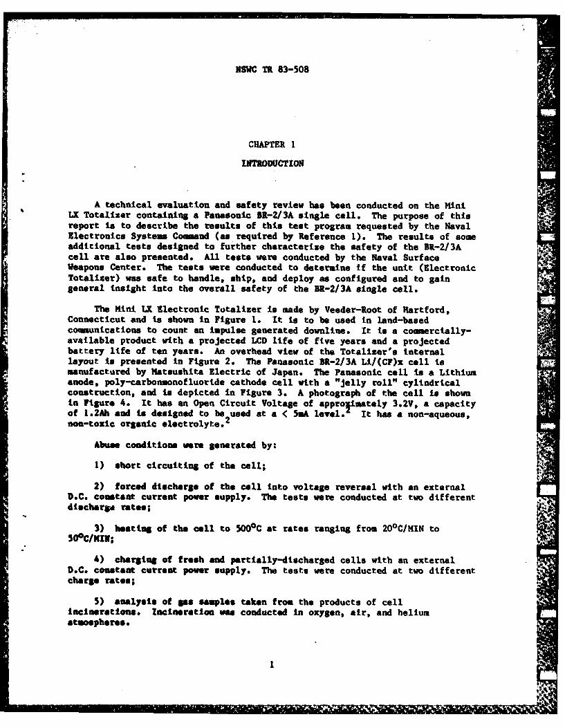
A technical evaluation and safety review has been conducted on the MiniLX Totalizer containing a Panasonic BR-2/3A single cell. The purpose of thisreport is to describe the results of this test program requested by the NavalElectronics Systems Command (as required by Reference 1). The results of someadditional tests designed to further characterize the safety of the BR-2/3Acell are also presented. All tests were conducted by the Naval SurfaceWeapons Center. The tests were conducted to determine if the unit (ElectronicTotalizer) was safe to handle, ship, and deploy as configured and to gaingeneral insight into the overall safety of the BR-2/3A single cell.
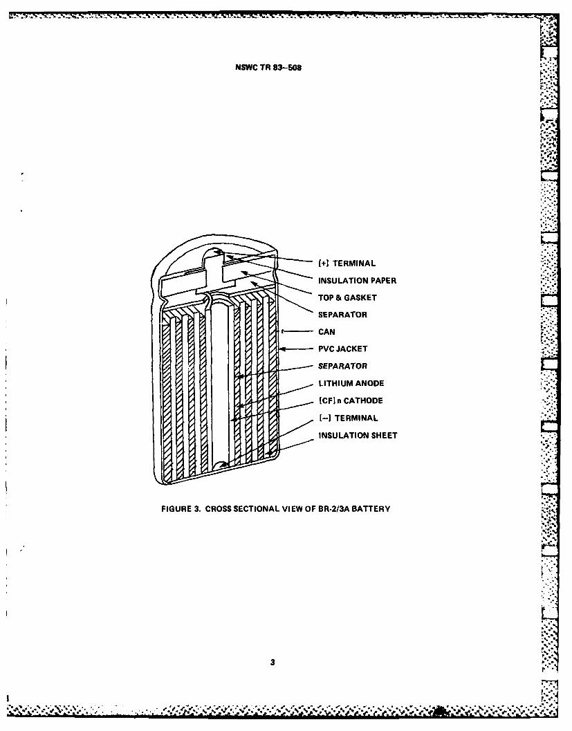
The Mini LX Electronic Totalizer is made by Veeder-Root of Hartford,Connecticut and is shown in Figure 1. It is to be used in land-basedcommunications to count an impulse generated downline. It is a commercially-available product with a projected LCD life of five years and a projectedbattery life of ten years. An overhead view of the Totalizer's internallayout is presented in Figure 2. The Panasonic BR-2/3A Ll/(CF)x cell ismanufactured by Matsushita Electric of Japan. The Panasonic cell is a Lithiumanode, poly-carbonmonofluoride cathode cell with a "Jelly roll" cylindricalconstruction, and is depicted in Figure 3. A photograph of the cell is shownin Figure 4. It has an Open Circuit Voltage of approtimately 3.2V, a capacityof 1.2Ah and is designed to be used at a < 5mA level. It has a non-aqueous,non-toxic organic electrolyte.
Abuse conditions were generated by:
1) short circuiting of the cell;
2) forced discharge of the cell into voltage reversal with an externalD.C. constant current power supply. The tests were conducted at two differentdischargd rates;
3) heating of the cell to 5009C at rates ranging from 20°C/MIN to50°ClN11;
4) charging of fresh and partially-discharged cells with an externalD.C. constant current power supply. The tests were conducted at two differentcharge rates;
5) analysis of gas samples taken from the products of cellincinerationes Incineration was conducted in oxygen, air, and heliumatmospheres.
iI

NSWC TR 83-508
IA
L . ..-
FIGURE 1. PHOTOGRAPH OF ELECTRONIC TOTALIZER
FIGURE 2. PHOTOGRAPH OF INTERNAL LAYOUT OF ELECTRONIC TOTALIZER
2
f- A
.'.
NSWC TR 83-508
+TERMINAL
INSULATION PAPER
TOP & GASKET
SEPARATOR
PVC JACKET ,,
SEPARATOR
LITHIUM ANODE
(CF] n CATHODE
-TERMINAL
INSULATION SHEET *4
FIGURE 3. CROSS SECTIONAL VIEW OF BR-213A BATTERY 4.p.
3
*~ .* o pV\z, e -

4~.* ...~.
NSWC TR 83-508
-4
S B,1.'
'B'p
p4. '4'4
4.
B.
-I'
rB'.
B'.
'.4'..4'.
'B
FIGURE 4. PHOTOGRAPH OF PANASONIC BR-2/3A CELL
4'
q
B a'
.4.
B.a.. B
'a..1
B..a..-
4.
.4a.'
.4
4 9.
_ I
NSWC TR 83-508
CHAPTER 2 6,C
EXPERIMENTAL
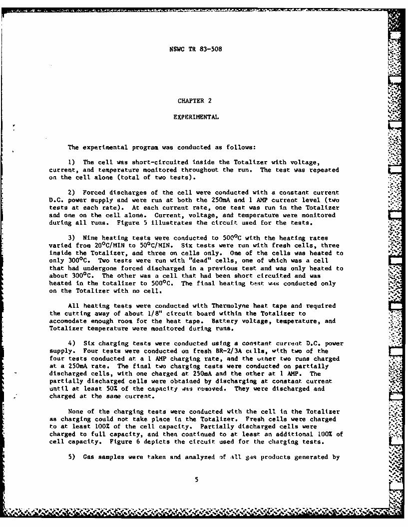
The experimental program was conducted as follows:
1) The cell was short-circuited inside the Totalizer with voltage,current, and temperature monitored throughout the run. The test was repeatedon the cell alone (total of two tests).
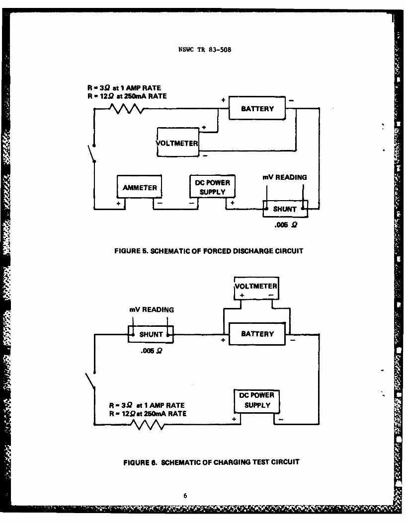
2) Forced discharges of the cell were conducted with a constant currentD.C. power supply and were run at both the 250mA and 1 AMP current level (twotests at each rate). At each current rate, one test was run in the Totalizerand one on the cell alone. Current, voltage, and temperature were monitoredduring all runs. Figure 5 illustrates the circuit used for the tests.
3) Nine heating tests were conducted to 5000C with the heating ratesvaried from 20°C/MIN to 50°C/MIN. Six tests were run with fresh cells, three V1inside the Totalizer, and three on cells only. One of the cells was heated toonly 3000 C. Two tests were run with "dead" cells, one of which was a cellthat had undergone forced discharged in a previous test and was only heated toabout 3000C. The other was a cell that had been short circuited and washeated in the totalizer to 500 0C. The final heating test was conducted onlyon the Totalizer with no cell.
All heating tests were conducted with Thermolyne heat tape and requiredthe cutting away of about 1/8" circuit board within the Totalizer toaccomodate enough room for the heat tape. Battery voltage, temperature, andTotalizer temperature were monitored during runs.
4) Six charging tests were conducted using a constant curreit D.C. powersupply. Four tests were conducted on fresh BR-2/3A ci.lls, w.th two of thefour tests conducted at a 1 AMP charging rate, and the uther two runs chargedat a 25OmA rate. The final two charging tests were conducted on partiallydischarged cells, with one charged at 250mA and the other at 1 AMP. Thepartially discharged cells were obtained by discharging at constant currentuntil at least 50% of the capacity 4as removed. They were discharged andcharged at the same current.
None of the charging tests were conducted with the cell in the Totalizeras charging could not take place in the Totalizer. Fresh cells were chargedto at least 100% of the cell capacity. Partially discharged cells werecharged to full capacity, and then continued to at least an additional 100% ofcell capacity. Figure 6 depicts the circuit used for the charging tests.
'. %*
5) Gas samples were taken and analyzed of all gas products generated by
5
NSWC TR 83-508
R -39 at IAMP RATER -129Q at 25OmA RATE+
VOLTMTER
++
mMV READING
AMMETER POWERER-30 tlMPRATE SUPPLYY
+ 4
FIGURE . SCHEMATIC OF REICHARG E CIRCUIT
6 TEE
NSWC TR 83-508
heating. The cells were placed in a pressure vessel in atmospheres of oxygen,helium, and air at a slight positive pressure ( < 5 p.s.i.g). Samples werethen heated with heat tape until combustion commenced (approximately 4500C).Then gas samples of the combustion products were taken from the pressure b -vessel. Voltage, temperatuare, and internal pressure of the vessel weremonitored The samples were sent to the National Bureau of Standards foranalysis .
Temperatures in all of the tests were monitored with type Kthermocouples. All reported cell temperatures are cell skin temperatures.The D.C. Power supply used in the tests was a LH 121 made by LambdaElectronics Corporation. The pressure transducer used was a PSI-Tronix modelPSIIOO-250-GI, and had lte, cailibrated for values between 0-150 p.s.i.g.
All tests conducted within the Totalizer required two small modifications : 'of the Totalizer unit to allow data aquisition, but in no way affected theoutcome of the tests. The modifications consisted of 1) drilling a smallhole on the top of the unit to allow thermocouples and heat tape leads intothe Totalizer; 2) soldering of leads from the battery terminals to existingposts leaving the rear of the unit. This was done to facilitate the chargingand forced discharge tests and the taking of voltage readings.
P.
%. I
7/8,
t-z..
*.%. e..
:.-*
7/8
. . .. . I - " ... . .. .. .. .. *
- 3ff . f 2_' .... . . Z. .. . .. s.....* :. .* .. '. . r :. . - -X:- 4....: w -ar_ c ' -.. . .. r.- -
NSWC TR 83-508
CHAPTER 3
RESULTS AND DISCUSSION
P.
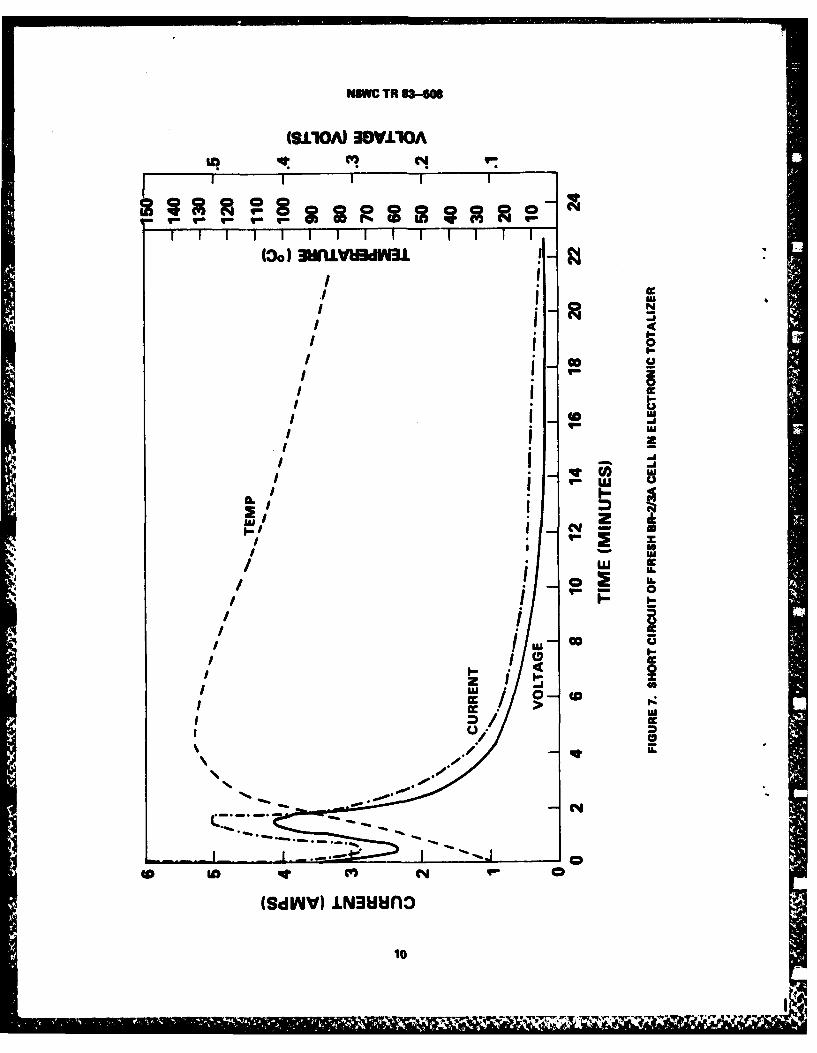
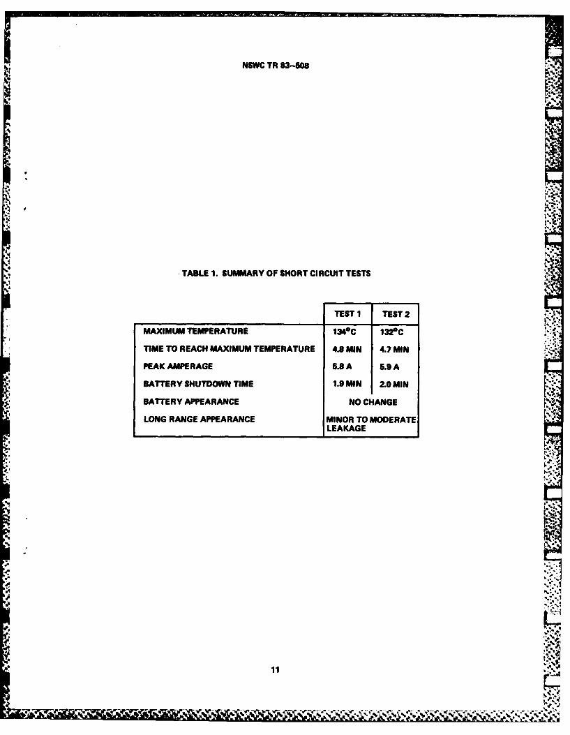
Both short circuit tests yielded similar results, and the results of atypical short circuit test is presented in Figure 7. A summary of significant 4.,.,.
data from both short circuit tests is listed in Table 1. The maximumtemperature obtained in both cases was slightly over 130 0C, and ventings didnot occur. The cell shut itself down in both cases at about two minutes.Cell shutdown occurs when the internal temperature reaches near 1300C and thepolypropylene mesh separator apparently fuses. Several weeks after the teststhe cells were re-examined and minor leakage was noticed. This was probablydue to warpage caused by softening of the plastic top and gasket (one piece)during the high temperatures of the tests. In addition, some minor crackingof the plastic PVC can jacket was noted.
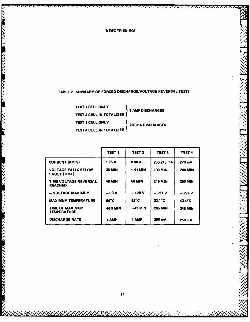
Figures 8 and 9 present the voltage, current and temperature data fromthe forced discharge tests. Table 2 summarizes the data obtained
from all .-
four forced discharge tests. Cells were held in voltage reversal for 100Z of *
cell capacity. Maximum temperature for the 250mA tests was 430C, and for the1 AEP tests it was 840C. No damage to the cell was noticed in any case, andsubsequent checks weeks after the tests revealed no cell leakage. As shown inFigure 9, the power supply voltage was turned up at 62 minutes. This was donebecause the voltage on the constant current power supply had originally beenlimited to slightly above the cell voltage. When it was apparent that thepower supply voltage was limiting the current level during cell voltagereversal, the power supply voltage was increased.
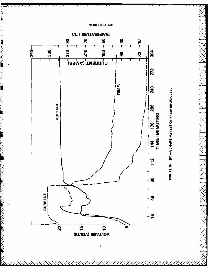
Figures 10 and 11 present the results oF tlie 250mA and 1 AMP chargingtests. During both tests "pops" from the cell were heard, and significantsmoking occurred. Ventings did occur; and in one test, the top insulationpaper was partially pushed out the top during the venting. A photograph oftwo ventings is presented in Figure 12. Ventings consisted of the pushing ofthe plastic cap from its seating to allow the release of internal pressure,but in general did not involve fire or flame. However, in one instance atapproximately 50 min. into a 1 AMP charging test, a minor and brief fireerupted from the end cap where the cell had vented earlier in the test. Thisincident occurred on a cell that had been discharged to one half capacity at IAMP before commencing charging. No other such incident was noted during anyof the charging tasrs. As can be seen by comparing the data curves, the 1 AMPrate produced much more erratic
behavior than did the 250mA rate. In both .. -.
cases, when the amperage fell from the specified charging rate, the voltagerose to 20 volts. This is due to a power supply limiting voltage of 20. Inall cases the PVC outer can jacket was cracked and discolored, but in no testwas the steel can affected.
LD
As previously described, a variety of heat tape tests were conducted.
9
"
L--1
'.t.
NW TR 83-5w
I9.L1OA) 3OVJ1O0AIn mt Vi C
(A dI UJ
ILI
UU
zzI -
NN
(SWV I,~u
* 00
...... .......
NSWC TR 83-508
TABLE 1. SUMMARY OF SHORT CIRCUIT TESTS
TEST I TEST 2
MAXIMUM TEMPERATURE 1340C 1320C
..
TIME TO REACH MAXIMUM TEMPERATURE 4.8 MIN 4.7 MIN
PEAK AMPERAGE 5.8 A 5.9 A
BATTERY SHUTDOWN TIME 1.9 MIN 2.0 MIN
BATTERY APPEARANCE NO CHANGE
LONG RANGE APPEARANCE MINOR TO MODERATELEAKAGE
,.a-s
q H.:.-
a,"
1A
.4p

NSWC TR 83-508
N
0VU I 0 uu_
0 Ei
CO(VW)V ccWf3
I 0 i0
LU
1000
I 0U/ - w
I 0
LU
cc 0NN
(SlIOA)30V110
12w

NSWC TR 83-508
1* 0 0 0 0
(S IV IN I 3I I I I
( C4a.%,
0 -0
CO (A
I NU
I>
'U
onoLO >
0I-2z
0L.
LU
N
IL
C-i
(SJ.1OA) 3OV1O0A
13
NSWC TR 83-508
TABLE 2. SUMMARY OF FORCED DISCHARGENOLTAGE REVERSAL TESTS
TEST 1CELL ONLY1 AMP DISCHARGES
TEST 2 CELL IN TOTALIZER
TEST CELLONLY250 mA DISCHARGES
TEST 4 CELL IN TOTALIZER~
TEST 1 TEST 2 TEST 3 TEST 4
CURRENT (AMPS) 1.05 A 0.98 A 250-275 mA 270 mA
VOLTAGE FALLS BELOW 38 MIN -41 MIN 190 MIN 240 MIN1 VOLT (TIME)
TIME VOLTAGE REVERSAL 48 MIN 50 MIN 245 MIN 250 MINREACHED
-VOLTAGE MAXIMUM -1.0 V -1.28 V -0.51 V -0.99 V
MAXIMUM TEMPERATURE 840 C 820C 32.1 0 C 43.40C
TIME OF MAXIMUM 46.5 MIN -49 MIN 245 MIN 245 MINTEMPERATURE
DISCHARGE RATE 1 AMP 1 AMP 250 mA 250 mA%.
%5
4 "1.
00 Ak.
NSWC TR 83-508
(3d) 3mIVU~dW31
* I- 0
*CV) CV) C1 N CV) *Cy)I (SdL'WV) 1LN~uunf:J j
I 'N
1%i
N CA
> LLI
1 0 0
00
z(
151
I- %

%..%7 - .7 -
NSWC TR 83-508
0 0 0 0 0 C 0
(SdAV) 1.N~&fun3
-j
zz-U N
cc CE
LU
0-
ILI
C4D
>1
S(SIOA) 30VI1OA
16

NSWC TR 83-508
FIGURE 12. PHOTOGRAPH OF TWO CELLS AFTER CHARGING
17 : *.
_____-7 7 .'% L, 7 ~ . ,. :1 .. &b. - T
NSWC TR 83-508
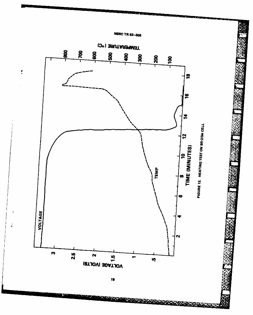
Those tests that were conducted to only 300"C vented between 200-2750C withloss of voltage, and some minior .s.iokiag occurred. Figure 13 presents the Ltypical data obtained for a fresh cell heated to 5000C. On all runs involving -fresh cells significant fire and flame erupted between 450-500°C. Initialvoltage drop off and venting occurred between 200-275 0C. In Figure 13 thetemperature rises sharply near 5000C where ignition commenced and a maximumtempIerature of slightly over 8000C was reached. Those tests on fresh cellsconducted in the Totalizer resulted in significant flames escaping from allseams of the Totalizer followed by the Totalizer catching on fire and beingtotally destroyed. Figure 14 shows the result of the fire on the Totalizer.
Those tests performed on dead cells produced large amounts of smoke atabout 4500C, but did not erupt into flames. A test was run on a Totalizerwith no cell, but containing a "dummy" cell consisting of a piece of coppertubing wrapped ia heat tape and heated to 5000C. This test was designed todetermine if the extreme nature of the fire was due only to the battery flamesor other internal components and/or plastic erupting into flames. As shown inFigure 15, the tests resulted in some melting and warpage of the Totalizer,but no significant fire or flame was noted. Upon later inspection it appearsthat some minor charring did occur to the outside case, but at no time was theTotalizer visibly in flames.
As indicated by the manufacturer, the cathode (poly-carbonmonofluoride)is thermally stable up to 4000C. The fact that the majority of incidents(fire or significant smoking) commenced when the battery skin-heat tapeinterface temperature was approximately 4500C indicates the probable cause ofthe ignition to be cathode thermal breakdown.
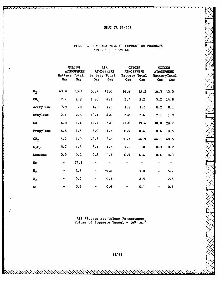
The results of the gas analysis of combustion products is presented inTable 3 The tests were run in a pressure vessel with a volume of169 In., and the ,maximum pressure developed during combustion wasapproximately 150 p.s.i.g. (Oxygen atmosphere). Listed in Table 3 for eachtest are two columns of percentages of the various gases. The first column,labeled battery gas, are the percentages that each individual gas compriseswhen compared to the total gas attributed to originating from the battery.The second column compares th. same individual gases to the total gases in thesample (including gases in the pre-combustion atmosphere). The array of gasesis largely comprised of low molecular weight hydrocarbons, some of which areunsaturated (Acetylene, Ethylene, and Propylene). Also present are -"
Fluorocarbons, C02, CO, Hydrogen and a low level of Benzene (<I%).
a lys.s was completed using Mass Spectroscopy. Species present wereidentified on the basis of their fragmentation patterns in combination withknowledge of the materials present in a fresh cell. Concentration values weredetermined from peak intensities which were compared with spectra obtainedfrom standard samples.
Ie
18 %
tAWC TR 83-sos
(0co
-- I-.
4
I fa
w ~
'pz
IU S
IN
IC
I C4
.
(SL1'O*V 30V.L-1OA

NSWC TR 83-508
FIGURE 14. TOTALIZER AFTER HEATING TEST FIRE
FIGURE 15. HEAT TEST OF TOTALIZER WITH NO CELL
20
NSWC TR 83-508
TABLE 3. GAS ANALYSIS OF COMBUSTION PRODUCTSAFTER CELL HEATING
HELIUM AIR OXYGEN OXYGENATMOSPHERE ATMOSPHERE ATMOSPHERE ATMOSPHERE
Battery Total Battery Total Battery Total BatteryTotalGas Gas Gas Gas Gas Gas Gas Gas
H2 43.8 10.1 33.2 13.0 16.4 15.2 16.3 15.0
CH4 12.7 2.9 10.6 4.2 5.7 5.2 5.2 14.8
Acetylene 7.9 1.8 4.0 1.6 1.2 1.1 0.2 0.1
Ethylene 12.1 2.8 10.1 4.0 2.8 2.6 2.1 1.9
CO 6.0 1.4 12.7 5.0 21.0 19.4 30.8 28.2
Propylene 6.6 1.5 3.0 1.2 0.5 0.4 0.6 0.5
CO2 4.2 1.0 22.5 8.8 50.7 46.9 44.1 40.5
CxFx 5.7 1.3 3.1 1.2 1.1 1.0 0.3 0.2
Benzene 0.9 0.2 0.8 0.3 0.5 0.4 0.4 0.3
e- 73.1 ......
N2 - 3.5 - 59.6 - 5.0 - 5.75.0" 5.7
02 - 0.2 - 0.5 - 2.5 - 2.4
Ar - 0.2 - 0.6 - 0.1 - 0.1
All Figures are Volume Percentages3 v*Volume of Pressure Vessel - 169 in. 3
21/22
*.% ~~.*..p*,* -... ..... .. *,.*...S "_ ,, - . % ' , -,.' % =,, ,. -. % . ,% ".-. % , % % -.. ,,=. % % . % * %~ ." , .%-,.

NSWC TR 83-508
REFERENCES
1. NAVSEAINST 9310.1, March 1979.2. Panasonic Lithium Batteries Technical Handbook, 1983.3. Dorko, William D., "Mass Spectrometric Analysis of Gaseous 0ff-gas Products of
Four Carbon Monofluoride Lithium Batteries," National Bureau of Standards* Report of Analysis 553-11-84, Feb., 1984.
do,
23/244
NSWC TR 83-508
DISTRIBUTION
Copies Copies
Defense Technical Information CommanderCenter Naval Weapons Center 1
Cameron Station Attn: Code 38 (E. Royce) 1Alexandria, VA 22314 12 Code 3852 (A. Fletcher) 1
Mr. L. Pracchia 1 *' *
Commander China Lake, CA 93555Naval Sea Systems CommandAttn: SEA 06R (D. J. Pastine) 1 Office of Naval Research
SEA 63R3 (F. Romano) 1 Attn: ONR 472 (G. Neece) 1SEA 9823 1 ONR 472 (J. Smith) 1SEA 06H (E. Daugherty) 2 800 N. Quincy StreetSEA 09G32 2 Arlington, VA 22217SEA 921AN(LCDR K. A. Tobin) 1 Commander
NAVSEA 543 1 Naval Weapons Support CenterWashington, DC 20362 Electrochemical Power Sources
DivisionCommander Attn: Code 305 (M. Robertson) 1Naval Ocean Systems Center Code 3061 (S. Shuler) 1Attn: Code 922 1 Code 7056 (R. Haag) 1
Code 712 (J. McCartney) 1 Crane, IN 47522Code 6343 (S. Spazk) I
San Diego, CA 92152 CommanderNaval Electronics Systems Command
Commander Attn: Code PME 124-31Naval Intelligence Support Center (A. H. Sobel) 1Attn: Code 362 (H. Ruskie) 1 NAVELEX 01K (A. Sliwa) 1Washington, DC 20390 40736 (W. J. Weingartner) 1
PME 110-242W (W. J. Hunter) IWashington, DC 20360
Office of Navy TechnologyAssociate Director CommanderAttn: Support Technology (072) 1 Naval Air Development Center800 N. Quincy Street Attn: Library 1Arlington, VA 22217 Warminster, PA 18974 *.>.*-
( k-.'C",
NSWC TR 83-508
DISTRIBUTION (Cont.)
Copies Copiesr
Chief of Naval Operations CommanderOperating Evaluation Group Naval Underwater Systems CenterWashington, DC 20360 1 Attn: Code 3642 (R. Lazar) 2
(J. Moden) 1Newport, RI 02840
David W. Taylor Naval Ship Research Navy Environmental Health Centerand Development Center Attn: J. R. Crawl, Head 1
Annapolis Laboratory Hazardous Mat. Eval. BranchAttn: Code 2724 (H. R. Urbach 1 Naval StationAnnapolis, MD 21401 Norfolk, VA 23511
US Army HQDA-DAEN-ASR-SL Altus CorporationWashington, DC 20314 1 1610 Crane Court
San Jose, CA 95112 1US Army Electronics CommandAttn: Code DELET-P (T. Reiss) 1 Yardney Electric Corporation
Code DRSEL-TR-PR Attn: Library(Dr. S. Gilman) 1 82 Mechanic Street
Fort Monmouth, NJ 07703 Pawcatuck, CT 02891
Air Force Aero Propulsion Lab Duracell Inc.Attn: AFAPL/OPE-1 (W. S. Bishop) 1 Attn: B. McDonald 1
AFAPL/OPE-1 (D. Marsh) 1 South BroadwayWright-Patterson AFB, OH 45433 Tarrytown, NY 10591
Central Intelligence Agency Power Conversion, Inc.Attn: OTS (C. Scuilla) 1 495 BoulevardWashington, DC 20505 Elmwood Park, NJ 07407 1
Headquarters Duracell Inc.Department of Transportation Laboratory for Physical ScienceU. S. Coast Guard Attn: Library 1Ocean Engineering Division Burlington, MA 01803Attn: GEOE-3/61 (R. Potter) 1Washington, DC 20590 Eagle-Picher Industries
Couples DepartmentNASA Goddard Space Flight Center Attn: Library 1Attn: Code 711 1 Joplin, MO 64801Greenbelt, MD 20771
Spartan ElectronicsNASA Langley Attn: Carroll H. Bush 1
* Attn: Code 488 (James Bene) 1 2400 East Ganson Street. Hampton, VA 23665 Jackson, MI 49202
NASA Johnson Space Center Sonatech, Inc.NASA Rd I Attn: R. Cyr 1Attn: Code EP5 (B. J. Bragg) 1 700 Francis Botello Road
Houston, TX 77058 Goleta, CA 93017
(2)
9 •

NSWC TR 83-508
DISTRIBUTION (cont.)
CopiesCopies
Lockheed Palo Alto Research Sanders AssociatesLaboratory Attn: George Disco
Lockheed Missiles & Space Co., 95 Canal StreetInc. Nashua, NH 03061
Attn: Library 13251 Hanover Street Wilson Greatbatch Ltd.Palo Alto, CA 94304 Attn: Dr. Arnold Keller
10,000 Wehrle DriveMcDonnell Douglas Corporation Clarence, NY 140311150 17th Street, NWSuite 500 EIC CorporationWashington, DC 20036 1 Attn: Dr. K. M. Abraham 1
55 Chapel StreetMagnavox Newton, MA 02158Department 529Attn: Carl Keuneke 1 General Electric Co.1313 Production Road Attn: Dr. R. W. Race, ManagerFort Wayne, IN 46808 Advance Programs Marketing
Room 2544A - OP#2 1RAY-0-VAC 100 Plastics AvenueAttn: R. F. Udell 1 Pittsfield, MA 01201
B. C. Bergum 1101 East Washington Avenue Norton Air Force BaseMadison, WI 53703 Attn: Code BMO/ENBE
(Capt. A. S. Alanis) 1Gould, Inc. Code AFISC/SES 1Gould Laboratories Norton AFB, CA 9240940 Gould CenterRolling Meadows, IL 60000 1 Battery Engineering
Attn: Dr. N. MarincicThe Boeing Company 80 Oak StreetAttn: Dr. A. C. Johnson 1 Newton, MA 02164PO Box 3707Seattle, WA 98124 NOAA Data Buoy Center
Attn: Mr. D. ScullyGTE Laboratories, Inc. NSTL STATION, MS 39529Attn: Library I40 Sylvan Road Teledyne ElectronicsWaltham, MA 02154 Attn: Mr. G. Lamb 1
649 Lawrence DriveMartin Marietta Aerospace Newbury Park, CA 91320Attn: John W. Wear 1PO Box 179 Mare Island Naval Ship YardDenver, CO 80201 Attn: Code 280.08
Stop 060 (R. Houlder) 1Vallejo, CA 94592
(3)

NSWC TR 83-508
DISTRIBUTION (cont.)
Copies Copies
GTE Sylvania Acoustic Systems, Inc.Attn: Dr. R. McDonald 1 Attn: Dr. James Fish 1189 B Street 600 Norman Firestone RoadNeedham Heights, MA 02194 Goleta, CA 93117
The Aerospace Corporation Dr. Robert Murphy 1Attn: Mr. Albert Heller 1 Advance Battery Group2350 East El Segundo Blvd. 269 Westwood RoadPO Box 92957 Lancaster, NY 14086Los Angeles, CA 90009
Jet Propulsion LaboratoryMr. David Yedwab 1 Code 198-220 (G. Halpert) 2AMCCOM 4800 Oak Grove DriveBldg. 61 South Pasadena, CA 91109Dover, NJ 07801
Mr. William DorkoMr. Les Hanson 1 B364 (CHEM)Code 3042 National Bureau of StandardsNaval Air Dev. Center Washington, DC 20234Warninster, PA 18974
Library of CongressHoneywell Incorporated Attn: Gift and Exchange Division 4Power Sources Center Washington, DC 20540Attn: Library104 Rock RoadHorsham, PA 19044
Internal Distribution:R30 1
. R33 (Mueller) 2. R33 (Staff) 20" R33 (Bis) 70
E35 1E431 9E432 3
P-i
OPO 909-719
(4)
,I-.k" 6- "-,, . -1
tlr' P '--q-t~lr'II' (-- "--+'I(L.IW'L It4(' t"tlll . .( +*q qi'--l-** * I+* I ' +* .. --*ri Jl. % * IW" I" % .+Ii 1 +'.+* j~l +* j I lj s4IA
...... ........
CAA
, e
St
I~~~S tt ~ w 1
-V1
Ml-b
* '0VAib. ILL
4A 1kf-