Embed Size (px)
Citation preview

GEL, 079
50,000 WATTS OF
FM
GENERAL ELECTRIC

Technical Data on New 50,000 -Watt
G -E Equipment Installed at
Our FM Proving Ground
by
W. R. DAVID
Radio and Television Department
GENERAL ELECTRIC COMPANY
Schenectady, N. Y.
Reprinted from September, 1941, issue of FM magazine Copyright 1941, M. B. Sleeper

,

FIG. 1. 50 -KW. G.E. FM TRANSMITTER SET UP FOR TESTS UNDER OPERATING CONDITIONS
50,000 -WATT FM TRANSMITTER
Technical Data on New G.E. Equipment Installed in the Helderbergs
BY W. R. DAVID *
HE photograph in Fig. 1 shows General Elec- tric'sT new 50 -kw. FM broadcast transmitter,
installed at the Helderberg station, twelve miles south of Schenectady. This is General Electric's "Proving Ground" for FM and tele- vision transmitters. Lacking factory floor space on account of National Defense radio work, the transmitter has been set up at the Helderberg station for tests which normally would be con- ducted in the factory.
General Design * In the early days of planning General Eli (tric FM broadcast transmitters, it was decided to design a basic unit which could be used as a low -power transmitter or as an exciter for the high power units. Two hun- dred fifty watts were determined upon as the output rating of the basic unit, this being con- sidered the smallest practical FM transmitter for any service area. Also, because of the cir-
* Radio and Television Department, General Electric
cuits and component parts required for generat- ing high -quality FM with the mean carrier frequency stability as specified by the Federal Communications Commission for broadcast service, there would be no appreciable saving in making a smaller transmitter.
In designing the high power units, three fac- tors were considered, namely, logical steps of power from the standpoint 0 economy and service area; possible tube complements with tubes then being developed by G. E. especially for high frequency applications such as FM and television; and, third, flexibility of the units in making up complete high power trans- mitters. Fig. 2 shows the manner in which it is possible to assemble high power transmitters from the basic unit and the intermediate power -amplifiers. As can be seen from the illus- trations, modern styling is employed so that the cabinets of the various units, when placed together, present an overall coordinated unit
Company, Schenectady, N. Y. assembly. 5

PAGE 6 50,000 -WATT FM TRANSMITTER
250 W.
TRANSMITTER
250 W 1000 W.
EXCITER PA
250 W. 3000 W.
EXCITER PA
250 W. 1000W 10000 W.
EXCITER I PA PA.
250 W 3000 W. 50000 W EXCITER I.PA PA
r MDRE THAN I 250W 1000W. 10000 W
EXCITER I.P A LPA ¡ 50000 W. I J RATED OUTPUT
250 WATTS 1000 WATTS 3000 WATTS
10000 WATTS 50000 WATTS
POWER INCREMENT RATIO POWER OUTPUT RANGE
50 TO 250 WATTS 1.4 250 TO 1000 WATTS 13 1000 TO 3000 WATTS
3.3 3000 TO 10000WATTS 15 10000 TO 50000 WATTS
G -E FM TRANSMITTER RATINGS
FIG. 2. COMBINATIONS OF FM UNITS REQUIRED TO DELIVER ANY GIVEN OUTPUT
Special Features * The following special features i the complete 50 -kw. transmitter are listed
to indicate the careful attention that has been given to reliability in general and specifically to continuity of service for transmitting com- mercial programs. 1. Simplified transmitter circuit design. See schematic diagram Fig. 5 and schematic block diagram Fig. 3.
2. Direct frequency modulation is accom- plished with only two tubes. Total frequency multiplication in the RF circuits requires nine. 3. Instant -acting electronic center frequency control is accomplished with only four tubes, by comparison of the transmitter output fre- quency with that of a crystal. The correction factor is approximately 100 to 1. There are no moving parts. 4. Temperature -compensated oscillator and discriminator circuits. 5. Voltage -regulated power supply for the modulator and oscillator. 6. The new G-31 crystal unit is hermetically sealed with built-in thermostat and heater. In addition, the crystal is the low temperature - coefficient type. 7. A spare crystal is furnished with the 50 -kw. transmitter, and provision is made in all trans- mitters for mounting a spare crystal with the
heater connected. It is possible to switch in- stantly from the active crystal to the spare and back to the active. 8. No temperature -controlled compartments other than the crystal chamber. 9. Tubes with air-cooling fins are used in the 3 -kw. amplifier. The 50 -kw. power -amplifier tubes are water-cooled and a closed water- cooling system is furnished (except for installa- tion piping). 10. The 3 -kw. and 50 -kw. RF amplifiers of the transmitter employ tubes developed by General Electric tube engineers especially for high frequency applications such as FM and television - the same engineers who developed many of the present-day broadcast transmitter tubes, notably, the GL -862, GL -858, GL -846, GL -207, GL -857B, and GL -869B. The type numbers of the new high -frequency tubes used in the 50 -kw. transmitter are GL -8002, and GL -880. The former is used with an air-cooled radiator. 11. Power cut-back is provided in the 50 -kw. transmitter. This is accomplished by a single switch control which cuts the 50 -kw. trans- mitter back to 3 kw. This feature avoids more than a momentary interruption of program in case of power -amplifier tube failure. It is pos- sible to service the 50 -kw. power -amplifier and its rectifier while the 3 -kw. unit is on the air, with complete safety to the operator.
50,000 -WATT FM TRANSMITTER PAGE 1
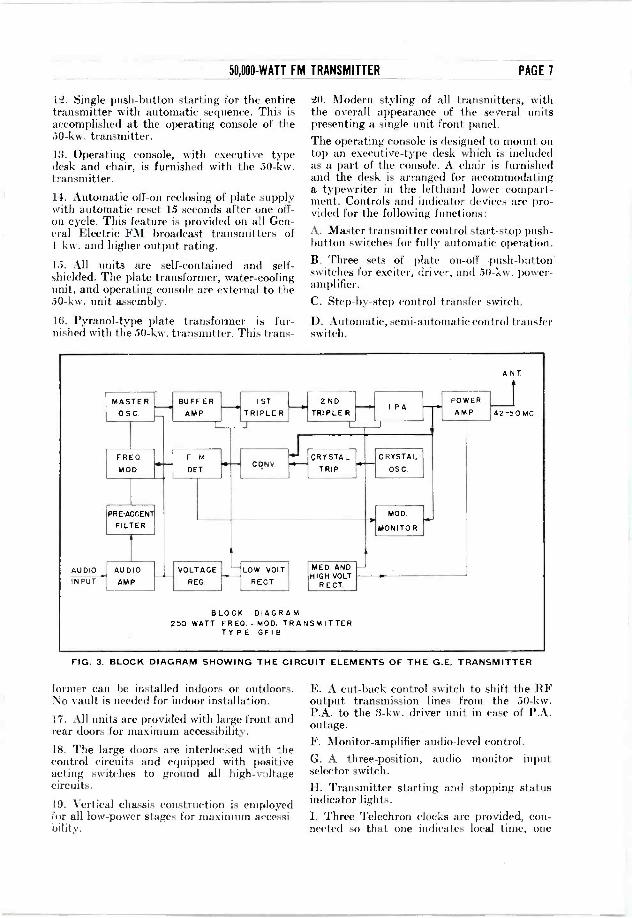
12. Single push-button starting for the entire transmitter with automatic sequence. This is accomplished at the operating console of the 50 -kw. transmitter. 13. Operating console, with executive type desk and chair, is furnished with the 50 -kw. transmitter. 14. Automatic off -on reclosing of plate supply with automatic reset 15 seconds after one off - on cycle. This feature is provided on all Gen- eral Electric FM broadcast transmitters of 1 kw. and higher output rating.
15. All units are self-contained and self - shielded. The plate transformer, water-cooling unit, and operating console are external to the 50 -kw. unit assembly.
16. Pyranol-type plate transformer is fur- nished with the 50 -kw. transmitter. This trans -
20. Modern styling of all transmitters, with the overall appearance of the several units presenting a single unit front panel. The operating console is designed to mount on top an executive -type desk which is included as a part of the console. A chair is furnished and the desk is arranged for accommodating a typewriter in the lefthand lower compart- ment. Controls and indicator devices are pro- vided for the following functions: A. Master transmitter control start -stop push- button switches for fully automatic operation. B. Three sets of plate on -off push-button switches for exciter, driver, and 50 -kw. power - amplifier.
C. Step-by-step control transfer switch.
D. Automatic, semi -automatic control transfer switch.
AUDIO INPUT
MASTER OSC.
BUFFER AMP
IST TRIPLER
2ND TRIPLE R
I.PA. POWER
AMP
FRED
MOD.
F -M DET
CONY CRYSTAL
TRIP
CRYSTAL
OSC.
PRE -ACCENT
FILTER MOD.
MONITOR
AU DIO
AMP
VOLTAGE
REG.
LOW VOLT
RECT
MED. AND HIGH VOLT
R ECT.
BLOCK DIAGRAM 250 WATT FRED. -MOD. TRANSMITTER
TYPE GFIB
ANT
42-50 MC
FIG. 3. BLOCK DIAGRAM SHOWING THE CIRCUIT ELEMENTS OF THE G.E. TRANSMITTER
former can be installed indoors or outdoors. No vault is needed for indoor installation.
17. All units are provided with large front and rear doors for maximum accessibility.
18. The large doors are interlocked with the control circuits and equipped with positive acting switches to ground all high -voltage circuits.
19. Vertical chassis construction is employed for all low -power stages for maximum accessi- bility.
E. A cut-back control switch to shift the RF output transmission lines from the 50 -kw. P.A. to the 3 -kw. driver unit in case of P.A. outage. F. Monitor -amplifier audio -level control. G. A three -position, audio monitor input selector switch. H. Transmitter starting and stopping status indicator lights. I. Three Telechron clocks are provided, con- nected so that one indicates local time, one

PAGE 8 50,000WATT FM TRANSMITTER
indicates time of carrier failure, and the third indicates total time cl carrier -off in case of an outage of the set during operation. A reset push button is provided to re -start the time - of -carrier -failure clock.
J. Extension instruments for installations
where a General Electric FM station monitor is employed. The instruments indicate center frequency deviation and percentage of modula- tion. Also, an adjustable peak modulation flasher is included.
The indicator light associated with each push-button switch is located inside the push button. The push buttons are appropriately colored and semi -transparent.
These and other convenience features are the result of General Electric's many years of ex- perience in building all types of radio trans- mitters for broadcast, television, emergency, Government and other services.
Technical Characteristics * The heart of the 50 -kw. transmitter and, for that matter, all General Electric FM broadcast transmitters, is the basic exciter unit. Its circuit is shown in the schematic diagram, Fig. 5, and the block diagram, Fig. 3. The fine characteristics of the basic exciter unit are unaltered in the amp- lifier stages. AM ripple, contributed by the amplifier, is made negligibly small in the out- put by a degenerative feed-back circuit in- ductively coupled to the final power -amplifier tank circuit.
The guaranteed performance characteristics for the 50,000 -watt transmitter are listed below.
FIG. 4. CLOSE- UP OF THE AN- TENNA USED AT THE HELDER- BERG STATION FOR TESTING THE 5 0 - K W .
TRANSMITTER, AND A VIEW FROM THE STA- TION OF THE VALLEY BELOW
Radio -Frequency Range * A single mean frequency in the range of 42 to 50 me., but all tuned cir- cuits can be adjusted to operate at any fre- quency within this band.
Power Output * The rated power output is 50 kw.

50,000 -WATT FM TRANSMITTER PAGE 9
Power Supply Requirements * The power consump- tion for the three units is as follows:
Exciter -1.25 kw., 115 volts, single-phase, 60 cycles
3000 -Watt Amplifier -8.25 kw., 230 volts, three-phase, 60 cycles
50,000 -Watt Amplifier* -109.00 kw., 230 volts, three-phase, 60 cycles
Over-all Power factor approximately 95%.
Audio -Frequency Response * Plus or minus 1 db from 30 to 16,000 cycles without pre -emphasis; with pre -emphasis, plus or minus 1 db of RMA pre -emphasis standard.
Audio Input Level * Normal, 0 vu; balanced "H" pad, incorporated in transmitter, permits lev- els from -7 vu to +8 vu in thirty %-db steps; input impedance, 600 ohms.
Harmonic Distortion * Less than 1% per cent for
1853 MODULATOR
65J7 AUDIO
H -PAD ATTENUATOR
6J5 OSCILLATOR
PRE - EMPHASIS CIRCUIT
AUDIO REGULATED M.V.
INPUT
TEMPERATURE COMPENSATORS
250 -WATT OUTPUT
J BUFFERTRPLER TRPLER GL 807 PA
GL -1611 Gl-161<..GL-80GL-B07
+b REGULATED H.V.
DISCRIMINATOR
6H6 DETECTOR
SEPARATOR CIRCUIT FOR INSTANT- ACTING FREQUENCY- STABILIZATION
O90 RELAY PREVENTS j OT OPERATION WITHOUT AI AI CRYSTAL STABIL-
IZATION.
TO PLATE CONTACTOR V
SIMPLIFIED SCHEMATIC. DIAGRAM G -E 250 -WATT FREQUENCY MODULATION BROADCAST
TYPE GF -I -B
GL -1614 CONVERTER
TRIPLER
GL -I614
TRANSMITTER
LIMZeril MOOULATDN INDICATOR
AUDIO
ACTS AS A
LIMITER
GL -8I0 PA
GL -810
TEMPERATURE CONTROLLED CRYSTAL
CRYSTAL OSCILLATOR MW TRIPLER
FIG. 5. FURTHER DETAILS OF THE TRANSMITTER CIRCUIT ARE GIVEN IN THIS DIAGRAM
Frequency Stability * Plus or minus 1000 cycles over a normal room temperature range.
Frequency Modulation * Normal frequency swing plus or minus 75 kilocycles, representing 100 per cent modulation.
* Power input for the amplifier is an estimate and includes power for the blowers and water cooling unit. Actual meas- urements are to be taken on the Helderberg transmitter.
1 Type GL -2A3 " ` 5Z3
] " 902 1 " " 6H6 1 " 6J5 3 " "6SJ7 2 " " 810
Exciter
modulating frequencies between 30 and 15,000 cycles, for carrier -frequency swing of ±75 kilocycles with pre -emphasis.
Intermodulation * Less than 1 per cent rms with audio input combinations of 400 and 700 cycles, and of 4000 and 7000 cycles.
FM Carrier Noise Level * Down 70 db at ±75 kilocycle swing.
TUBE COMPLEMENT
3 -kw. Amplifier
4 Type GL -866A/ 866 Type GL -8002R 5 " 1614 Ii " " 872.E 1 " " 1853
1 " " VR105-30 3 " " 807
50 -kw. Amplifier and Rectifier
2 Type GL -880 6 " " 869B 2 " " 866A/866 1 " " 83V 1 " 83 1 " " 6AC7 2 " " 6L6

PAGE 10 50,000 -WATT FM TRANSMITTER
AM Carrier Noise Level * 60 db below loo per cent amplitude modulation.
Output Coupling * The output circuit is arranged for concentric transmission line feed to the antenna and the coupling is variable from front of panel. Provision is made to tune out the reactance of the output coupling circuit.
Tube Complement * The complete complement of
Water-cooling unit (including water) 3000 " Operating console 350 "
It should be noted that the values stated represent guarantees rather than actual per- formance. As a matter of fact, the measured characteristics of the transmitter are expected to be appreciably better. Physical Layout * The 50 -kw. transmitter com- prises five self-contained and shielded units
10 FT. -+- ..18FT8
G
+18FT2¡ I-
LAVATORY
6 FT-H
ZZ. 20 FT I"
Left F- sFTE'-I °._/
RECEPTION ROOM
_ - 20 ;T
oT RAI L
T I
SO FT.
(
10 FT.
.TUBE STORAGE a
WORK SHOP
8 -T -L RECEIVER
AUDIO ROOM
OFFICE
20 FT.
11
A - 250 -WATT EXCITER E - 50 -KW CONTROL SECTION
B - 3 -KW AMPLIFIER & RECTIFIER F -OPERATOR'S CONSOLE
C - 50 -KW POWER AMPLIFIER R -F SECTION G - WATER COOLING UNIT
D -50 -KW RECTIFIER SECTION H- MAIN PLATE TRANSFORMER (PYRANOL COOLED)
ITEMS G & H MAY BE INSTALLED IN BASEMENT
FIG. 6. SUGGESTED LAYOUT FOR A TRANSMITTER
tubes for the transmitter units are given in the accompanying table.
Total cost one set of tubes $2903.44. Two sets of tubes are furnished with the transmit- ter. Provision is made for mounting one of the spare 869B tubes in the main rectifier where it is kept in readiness for quick substitution in one of the other positions.
Dimensions * For overall dimensions, see Fig. 6. The net weights of the units are: Exciter 635 lbs. 3 -kw. amplifier 1182 " 50 kw. amplifier 1500 " Main rectifier 2000 " Control unit 1400 lbs. Plate transformer 4500 "
ROOM TO HOUSE THE 50 -KW. EQUIPMENT
each 6% feet high. A suggested arrangement is given, with dimensions, in Fig. 6. The units are identified as follows, from left to right facing the front panel.
250 -watt basic exciter unit 3 -kw, intermediate power -amplifier 50 -kw. power -amplifier Main rectifier for power -amplifier Relay and contactor control unit
In addition, there are three external units: Plate transformer Water-cooling assembly Operating console
All units are designed for maximum accessi- bility of components to facilitate inspection and maintenance. All tubes in the equipment are replaceable without removal of shielding.
50,000 -WATT FM TRANSMITTER PAGE 11
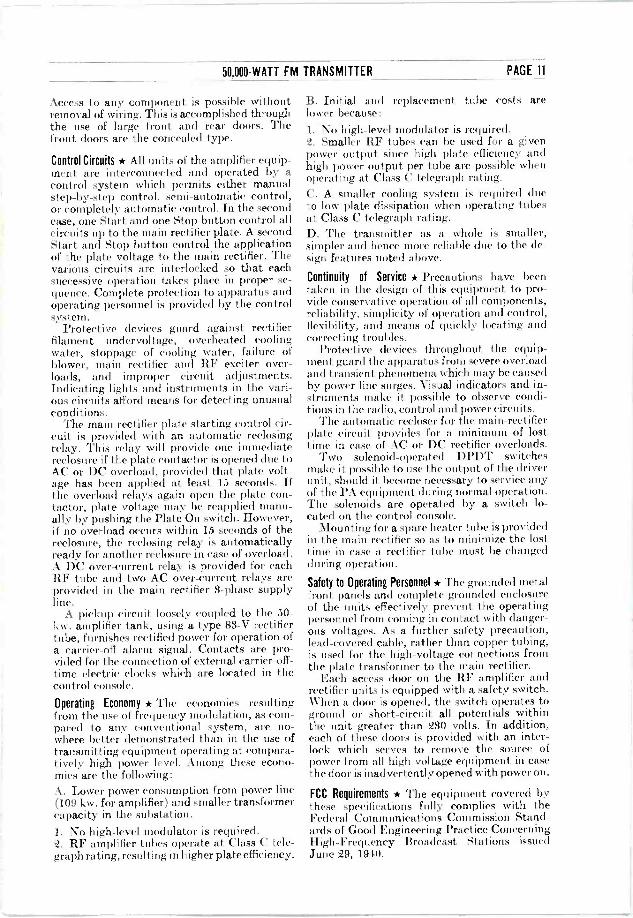
Access to any component is possible without removal of wiring. This is accomplished through the use of large front and rear doors. The front doors are the concealed type.
Control Circuits * All units of the amplifier equip- ment are interconnected and operated by a control system which permits either manual step-by-step control, semi -automatic control, or completely automatic control. In the second case, one Start and one Stop button control all circuits up to the main rectifier plate. A second Start and Stop button control the application of the plate voltage to the main rectifier. The various circuits are interlocked so that each successive operation takes place in proper se- quence. Complete protection to apparatus and operating personnel is provided by the control system.
Protective devices guard against rectifier filament undervoltage, overheated cooling water, stoppage of cooling water, failure of blower, main rectifier and RF exciter over- loads, and improper circuit adjustments. Indicating lights and instruments in the vari- ous circuits afford means for detecting unusual conditions.
The main rectifier plate starting control cir- cuit is provided with an automatic reclosing relay. This relay will provide one immediate reclosure if the plate contactor is opened due to AC or DC overload, provided that plate volt- age has been applied at least 15 seconds. If the overload relays again open the plate con- tactor, plate voltage may be reapplied manu- ally by pushing the Plate On switch. However, if no overload occurs within 15 seconds of the reclosure, the reclosing relay is automatically ready for another reclosure in case of overload. A DC over -current relay is provided for each RF tube and two AC over -current relays are provided in the main rectifier 3 -phase supply line.
A pickup circuit loosely coupled to the 50 - kw. amplifier tank, using a type 83-V rectifier tube, furnishes rectified power for operation of a carrier -off alarm signal. Contacts are pro- vided for the connection of external carrier -off - time electric clocks which are located in the control console.
Operating Economy * The economies resulting from the use of frequency modulation, as com- pared to any conventional system, are no- where better demonstrated than in the use of transmitting equipment operating at compara- tively high power level. Among these econo- mies are the following: A. Lower power consumption from power line (109 kw. for amplifier) and smaller transformer capacity in the substation. 1. No high-level modulator is required. 2. RF amplifier tubes operate at Class C tele- graph rating, resulting in higher plate efficiency.
B. Initial and replacement tube costs are lower because:
1. No high-level modulator is required. Q. Smaller RF tubes can be used for a given power output since high plate efficiency and high power output per tube are possible when operating at Class C telegraph rating. C. A smaller cooling system is required due to low plate dissipation when operating tubes at Class C telegraph rating. D. The transmitter as a whole is smaller, simpler and hence more reliable due to the de- sign features noted above.
Continuity of Service * Precautions have been taken in the design of this equipment to pro- vide conservative operation of all components, reliability, simplicity of operation and control, flexibility, and means of quickly locating and correcting troubles.
Protective devices throughout the equip- ment guard the apparatus from severe overload and transient phenomena which may be caused by power line surges. Visual indicators and in- struments make it possible to observe condi- tions in the radio, control and power circuits.
The automatic recloser for the main -rectifier plate circuit provides for a minimum of lost time in case of AC or DC rectifier overloads.
Two solenoid -operated DPDT switches make it possible to use the output of the driver unit, should it become necessary to service any of the PA equipment during normal operation. The solenoids are operated by a switch lo- cated on the control console.
Mounting for a spare heater tube is provided in the main rectifier so as to minimize the lost time in case a rectifier tube must be changed during operation.
Safety to Operating Personnel * The grounded metal front panels and complete grounded enclosure of the units effectively prevent the operating personnel from coming in contact with danger- ous voltages. As a further safety precaution, lead -covered cable, rather than copper tubing, is used for the high -voltage connections from the plate transformer to the main rectifier.
Each access door on the RF amplifier and rectifier units is equipped with a safety switch. When a door is opened, the switch operates to ground or short-circuit all potentials within the unit greater than 230 volts. In addition, each of these doors is provided with an inter- lock which serves to remove the source of power from all high voltage equipment in case the (loor is inadvertently opened with power on.
FCC Requirements * The equipment covered by these specifications fully complies with the Federal Communications Commission Stand- ards of Good Engineering Practice Concerning High -Frequency Broadcast Stations issued June 29, 1940.

RADIO AND TELEVISION DEPARTMENT
GENERAL (J1+) ELECTRIC SCHENECTADY, N. Y.
10-41 (2500) Filing No. 6914
Printed in
U.S.A.