Embed Size (px)
Citation preview
Operator’s Manual
1000 and 2000Product FamiliesInternationalModels
OM4118EN
C
M
Y
CM
MY
CY
CMY
K
OM4118EN F.pdf 9/30/05 8:46:29 AMOM4118EN F.pdf 9/30/05 8:46:29 AM
Allison Transmission
INTERNATIONAL MODELS
Operator’sManual
2005 MAY
Rev. 1 2005 SEPTEMBER
OM4118EN
1000 and 2000 Product FamiliesIncludes Allison 4
th
Generation Controls
1000 2100 2200 25001000 MH 2100 MH 2200 MH 2500 MH1000 SP 2100 SP 2200 SP 2500 SP
Printed in USA Copyright © 2005 General Motors Corporation

2
NOTES
TABLE OF CONTENTS
INTRODUCTIONKEEPING THAT ALLISON ADVANTAGE . . . . . . . . . . . . . . . . . . . . . . . . 7A BRIEF DESCRIPTION OF THE ALLISON 1000 AND 2000 PRODUCT FAMILYTRANSMISSIONS . . . . . . . . . . . . . . . . . . . . . . . . . . . . . . . . . . . . . . 11ELECTRONIC CONTROL SYSTEM . . . . . . . . . . . . . . . . . . . . . . . . . . . 11TORQUE CONVERTER . . . . . . . . . . . . . . . . . . . . . . . . . . . . . . . . . . . 12PLANETARY GEARS AND CLUTCHES . . . . . . . . . . . . . . . . . . . . . . . . 13COOLER CIRCUIT . . . . . . . . . . . . . . . . . . . . . . . . . . . . . . . . . . . . . . 13
SHIFT SELECTORSDESCRIPTION OF AVAILABLE TYPES . . . . . . . . . . . . . . . . . . . . . . . . . 14OPERATION OF THE SHIFT SELECTOR . . . . . . . . . . . . . . . . . . . . . . . . 14RANGE SELECTION—ALL 1000 AND 2200 TRANSMISSION MODELS WITHPARK PAWL AND P (PARK) POSITION . . . . . . . . . . . . . . . . . . . . . . . . 17RANGE SELECTION—ALL 2100 AND 2500 TRANSMISSION MODELS WITHPB (AUTO-APPLY PARKING BRAKE) POSITION . . . . . . . . . . . . . . . . . . 21RANGE SELECTION—ALL 1000 AND 2000 PRODUCT FAMILYTRANSMISSIONS WITHOUT EITHER P (PARK) OR PB (AUTO-APPLYPARKING BRAKE) POSITIONS . . . . . . . . . . . . . . . . . . . . . . . . . . . . . . 25
DRIVING TIPSPREVENT MAJOR PROBLEMS . . . . . . . . . . . . . . . . . . . . . . . . . . . . . . 29TURNING THE VEHICLE ON/OFF . . . . . . . . . . . . . . . . . . . . . . . . . . . 29MAXIMUM VEHICLE LOADING . . . . . . . . . . . . . . . . . . . . . . . . . . . . 30ACCELERATOR CONTROL . . . . . . . . . . . . . . . . . . . . . . . . . . . . . . . . 31PRIMARY/SECONDARY SHIFT SCHEDULES . . . . . . . . . . . . . . . . . . . . 31KICKDOWN . . . . . . . . . . . . . . . . . . . . . . . . . . . . . . . . . . . . . . . . . . 31OUTPUT SPEED INDICATOR . . . . . . . . . . . . . . . . . . . . . . . . . . . . . . . 32DIAGNOSTIC CODES . . . . . . . . . . . . . . . . . . . . . . . . . . . . . . . . . . . . 32RANGE INHIBIT(ED) LIGHT . . . . . . . . . . . . . . . . . . . . . . . . . . . . . . . 32CHECK TRANS OR MALFUNCTION INDICATOR LIGHT . . . . . . . . . . . . 32SHIFT INHIBITS . . . . . . . . . . . . . . . . . . . . . . . . . . . . . . . . . . . . . . . 33USING THE ENGINE TO SLOW THE VEHICLE . . . . . . . . . . . . . . . . . . . 35RANGE PRESELECTION . . . . . . . . . . . . . . . . . . . . . . . . . . . . . . . . . . 36REVERSE . . . . . . . . . . . . . . . . . . . . . . . . . . . . . . . . . . . . . . . . . . . . 37REFUSE PACKER STEP SWITCH . . . . . . . . . . . . . . . . . . . . . . . . . . . . 37TWO-SPEED AXLE (Some General Transmission Applications) . . . . . . . . . . . 37DRIVING ON SNOW OR ICE . . . . . . . . . . . . . . . . . . . . . . . . . . . . . . . 37ROCKING OUT . . . . . . . . . . . . . . . . . . . . . . . . . . . . . . . . . . . . . . . . 38OPERATING TEMPERATURES . . . . . . . . . . . . . . . . . . . . . . . . . . . . . . 38HIGH FLUID TEMPERATURE . . . . . . . . . . . . . . . . . . . . . . . . . . . . . . 39
3
PARKING BRAKE . . . . . . . . . . . . . . . . . . . . . . . . . . . . . . . . . . . . . . 39PARK PAWL . . . . . . . . . . . . . . . . . . . . . . . . . . . . . . . . . . . . . . . . . . 40PARKING/LEAVING VEHICLE WITH ENGINE RUNNING . . . . . . . . . . . . 41TOWING OR PUSHING . . . . . . . . . . . . . . . . . . . . . . . . . . . . . . . . . . . 42SURGING NATURAL GAS ENGINES . . . . . . . . . . . . . . . . . . . . . . . . . . 43
POWER TAKEOFFPOWER TAKEOFF (PTO) SYSTEMS . . . . . . . . . . . . . . . . . . . . . . . . . . 44TURBINE-DRIVEN POWER TAKEOFF (PTO) . . . . . . . . . . . . . . . . . . . . . 44SPLIT-SHAFT POWER TAKEOFF (PTO) . . . . . . . . . . . . . . . . . . . . . . . . 48
CARE AND MAINTENANCEPERIODIC INSPECTIONS AND CARE . . . . . . . . . . . . . . . . . . . . . . . . . 49IMPORTANCE OF PROPER TRANSMISSION FLUID LEVEL . . . . . . . . . . . 50TRANSMISSION FLUID CHECK . . . . . . . . . . . . . . . . . . . . . . . . . . . . . 50KEEPING FLUID CLEAN . . . . . . . . . . . . . . . . . . . . . . . . . . . . . . . . . . 54FLUID RECOMMENDATIONS . . . . . . . . . . . . . . . . . . . . . . . . . . . . . . 54TRANSMISSION FLUID AND FILTER CHANGE INTERVALS . . . . . . . . . . 56TRANSMISSION FLUID CONTAMINATION . . . . . . . . . . . . . . . . . . . . . 58TRANSMISSION FLUID AND FILTER CHANGE PROCEDURE . . . . . . . . . 59BREATHER . . . . . . . . . . . . . . . . . . . . . . . . . . . . . . . . . . . . . . . . . . . 61
DIAGNOSTICSDIAGNOSTIC CODES AND TOOLS . . . . . . . . . . . . . . . . . . . . . . . . . . . 62
CUSTOMER SERVICEOWNER ASSISTANCE . . . . . . . . . . . . . . . . . . . . . . . . . . . . . . . . . . . 63SERVICE LITERATURE . . . . . . . . . . . . . . . . . . . . . . . . . . . . . . . . . . . 65ALLISON TRANSMISSION REGIONAL OFFICES . . . . . . . . . . . . . . . . . . 66
4

TRADEMARK USAGEThe following trademarks are the property of the companies indicated:
• DEXRON® is a registered trademark of the General Motors Corporation.
• TranSynd™ is a trademark of Castrol Ltd.
• Allison DOC™ is a trademark of General Motors Corporation.
5
WARNINGS, CAUTIONS, NOTES
IT IS YOUR RESPONSIBILITY to be completely familiar with the warningsand cautions described in this manual. It is, however, important to understand thatthese warnings and cautions are not exhaustive. Allison Transmission could notpossibly know, evaluate, and advise the service trade of all conceivable ways inwhich service might be done or of the possible hazardous consequences of eachway. The vehicle manufacturer is responsible for providing information related tothe operation of vehicle systems (including appropriate warnings, cautions, andnotes). Consequently, Allison Transmission has not undertaken any such broadevaluation. Accordingly, ANYONE WHO USES A SERVICE PROCEDUREOR TOOL WHICH IS NOT RECOMMENDED BY ALLISONTRANSMISSION OR THE VEHICLE MANUFACTURER MUST first bethoroughly satisfied that neither personal safety nor equipment safety will bejeopardized by the service methods selected.
Proper service and repair is important to the safe, reliable operation of theequipment. The service procedures recommended by Allison Transmission (or thevehicle manufacturer) and described in this manual are effective methods forperforming service operations. Some of these service operations require the use oftools specially designed for the purpose. The special tools should be used whenand as recommended.
Three types of headings are used in this manual to attract your attention. Thesewarnings and cautions advise of specific methods or actions that can result inpersonal injury, damage to the equipment, or cause the equipment to becomeunsafe.
WARNING: A warning is used when an operating procedure, practice,etc., if not correctly followed, could result in personal injury or loss oflife.
CAUTION: A caution is used when an operating procedure, practice,etc., if not strictly observed, could result in damage to or destruction ofequipment.
NOTE: A note is used when an operating procedure, practice, etc., isessential to highlight.
6
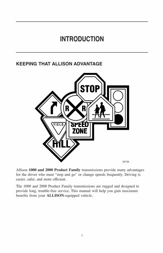
KEEPING THAT ALLISON ADVANTAGE
Allison 1000 and 2000 Product Family transmissions provide many advantagesfor the driver who must “stop and go” or change speeds frequently. Driving iseasier, safer, and more efficient.
The 1000 and 2000 Product Family transmissions are rugged and designed toprovide long, trouble-free service. This manual will help you gain maximumbenefits from your ALLISON-equipped vehicle.
INTRODUCTION
7
TURB
INE
SPE
EDSE
NSO
R
BREA
THER
ENG
INE
SPE
EDSE
NSO
R
NSBU
SW
ITCH
PARK
ING
BRA
KEM
OUN
TING
PRO
VISI
ON
OUT
PUT
SPE
ED S
ENSO
R
SELE
CTO
R S
HAFT
CONT
ROL
MAI
N O
IL F
ILTE
R
V066
92.0
0.03
SAE
6-BO
LTPT
O P
AD
AVAI
LABL
EO
IL F
ILL
TUB
ELO
CATI
ON
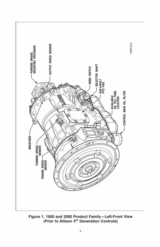
Figure 1. 1000 and 2000 Product Family—Left-Front View(Prior to Allison 4th Generation Controls)
8
TURB
INE
SPE
ED S
ENSO
R
BREA
THER
ENG
INE
SPE
EDSE
NSO
R
PARK
ING
BRA
KEM
OUN
TING
PRO
VISI
ON
OUT
PUT
SPE
ED S
ENSO
R
CONT
ROL
MAI
N O
IL F
ILTE
R
SAE
6-BO
LT P
TO P
AD
AVAI
LABL
E O
IL F
ILL
TUB
E L
OCA
TIO
N
SELE
CTO
R S
HAFT
V066
92.0
2.00
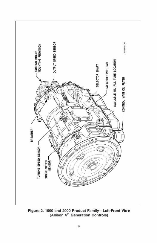
Figure 2. 1000 and 2000 Product Family—Left-Front View(Allison 4th Generation Controls)
9
TURB
INE
SPE
EDSE
NSO
R
OUT
PUT
SPE
EDSE
NSO
R
BREA
THER
ENG
INE
SPE
EDSE
NSO
R
MO
UNTI
NG P
AD(S
AE #
3 H
OUS
ING
ONL
Y)
MAI
N E
LECT
RICA
LCO
NNEC
TOR
OPT
IONA
LTA
CHO
GRA
PHPR
OVI
SIO
N
V066
93.0
0.03
SAE
6-BO
LTPT
O P
ADAVAI
LABL
EO
IL F
ILL
TUB
ELO
CATI
ON
COO
LER
PO
RTS
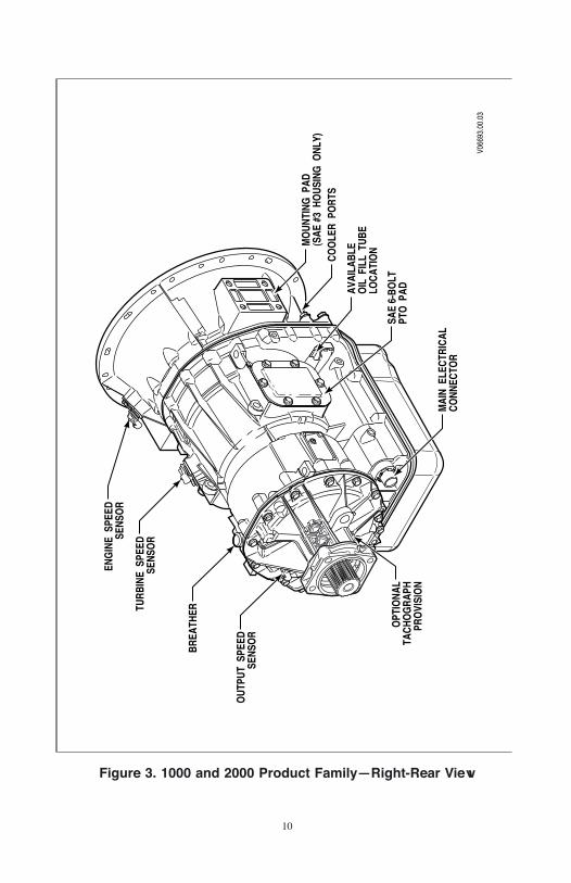
Figure 3. 1000 and 2000 Product Family—Right-Rear View
10
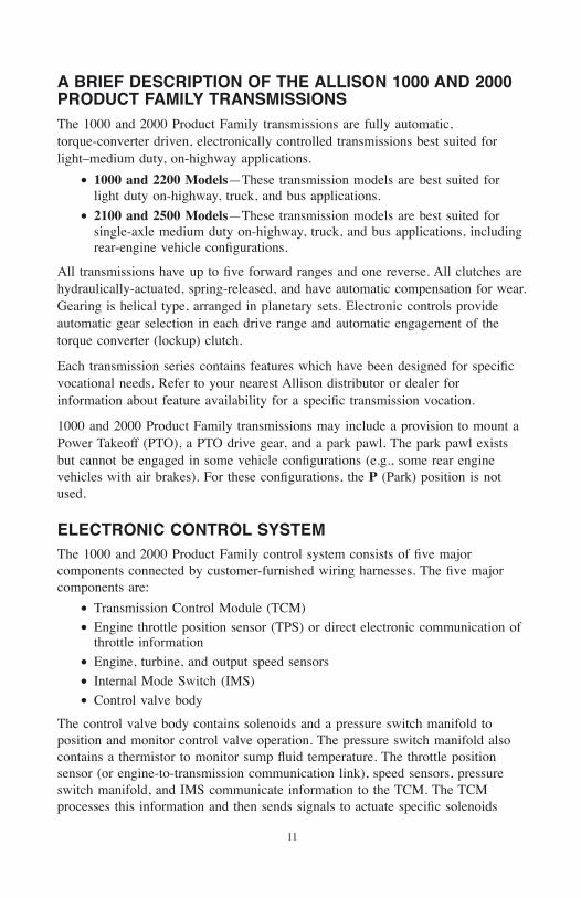
A BRIEF DESCRIPTION OF THE ALLISON 1000 AND 2000PRODUCT FAMILY TRANSMISSIONSThe 1000 and 2000 Product Family transmissions are fully automatic,torque-converter driven, electronically controlled transmissions best suited forlight–medium duty, on-highway applications.
• 1000 and 2200 Models—These transmission models are best suited forlight duty on-highway, truck, and bus applications.
• 2100 and 2500 Models—These transmission models are best suited forsingle-axle medium duty on-highway, truck, and bus applications, includingrear-engine vehicle configurations.
All transmissions have up to five forward ranges and one reverse. All clutches arehydraulically-actuated, spring-released, and have automatic compensation for wear.Gearing is helical type, arranged in planetary sets. Electronic controls provideautomatic gear selection in each drive range and automatic engagement of thetorque converter (lockup) clutch.
Each transmission series contains features which have been designed for specificvocational needs. Refer to your nearest Allison distributor or dealer forinformation about feature availability for a specific transmission vocation.
1000 and 2000 Product Family transmissions may include a provision to mount aPower Takeoff (PTO), a PTO drive gear, and a park pawl. The park pawl existsbut cannot be engaged in some vehicle configurations (e.g., some rear enginevehicles with air brakes). For these configurations, the P (Park) position is notused.
ELECTRONIC CONTROL SYSTEMThe 1000 and 2000 Product Family control system consists of five majorcomponents connected by customer-furnished wiring harnesses. The five majorcomponents are:
• Transmission Control Module (TCM)
• Engine throttle position sensor (TPS) or direct electronic communication ofthrottle information
• Engine, turbine, and output speed sensors
• Internal Mode Switch (IMS)
• Control valve body
The control valve body contains solenoids and a pressure switch manifold toposition and monitor control valve operation. The pressure switch manifold alsocontains a thermistor to monitor sump fluid temperature. The throttle positionsensor (or engine-to-transmission communication link), speed sensors, pressureswitch manifold, and IMS communicate information to the TCM. The TCMprocesses this information and then sends signals to actuate specific solenoids
11
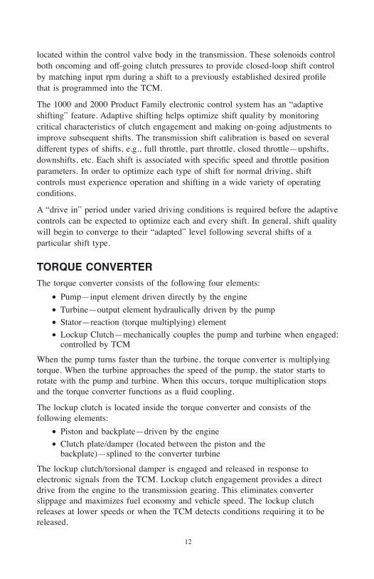
located within the control valve body in the transmission. These solenoids controlboth oncoming and off-going clutch pressures to provide closed-loop shift controlby matching input rpm during a shift to a previously established desired profilethat is programmed into the TCM.
The 1000 and 2000 Product Family electronic control system has an “adaptiveshifting” feature. Adaptive shifting helps optimize shift quality by monitoringcritical characteristics of clutch engagement and making on-going adjustments toimprove subsequent shifts. The transmission shift calibration is based on severaldifferent types of shifts, e.g., full throttle, part throttle, closed throttle—upshifts,downshifts, etc. Each shift is associated with specific speed and throttle positionparameters. In order to optimize each type of shift for normal driving, shiftcontrols must experience operation and shifting in a wide variety of operatingconditions.
A “drive in” period under varied driving conditions is required before the adaptivecontrols can be expected to optimize each and every shift. In general, shift qualitywill begin to converge to their “adapted” level following several shifts of aparticular shift type.
TORQUE CONVERTERThe torque converter consists of the following four elements:
• Pump—input element driven directly by the engine
• Turbine—output element hydraulically driven by the pump
• Stator—reaction (torque multiplying) element
• Lockup Clutch—mechanically couples the pump and turbine when engaged;controlled by TCM
When the pump turns faster than the turbine, the torque converter is multiplyingtorque. When the turbine approaches the speed of the pump, the stator starts torotate with the pump and turbine. When this occurs, torque multiplication stopsand the torque converter functions as a fluid coupling.
The lockup clutch is located inside the torque converter and consists of thefollowing elements:
• Piston and backplate—driven by the engine
• Clutch plate/damper (located between the piston and thebackplate)—splined to the converter turbine
The lockup clutch/torsional damper is engaged and released in response toelectronic signals from the TCM. Lockup clutch engagement provides a directdrive from the engine to the transmission gearing. This eliminates converterslippage and maximizes fuel economy and vehicle speed. The lockup clutchreleases at lower speeds or when the TCM detects conditions requiring it to bereleased.
12
The torsional damper absorbs engine torsional vibration to prevent transmittingvibrations through the powertrain.
PLANETARY GEARS AND CLUTCHESA series of three helical planetary gear sets and shafts provides the mechanicalgear ratios and direction of travel for the vehicle. The planetary gear sets arecontrolled by five multiplate clutches that work in pairs to produce up to fiveforward speeds and one reverse speed. The clutches are applied and releasedhydraulically in response to electronic signals from the TCM to the appropriatesolenoids.
COOLER CIRCUITThe transmission fluid is cooled by a remote-mounted oil cooler. The bottom ofthe transmission torque converter housing provides for the direct mounting of acontrol main filter and includes two ports to facilitate the attachment of the oilcooler lines.
13
DESCRIPTION OF AVAILABLE TYPESThe 1000 and 2000 Product Family transmissions use lever-type shift selectors.The shift positions on the shift selector can vary according to the OEM-suppliedshift selector installed.
OPERATION OF THE SHIFT SELECTORThe shift selector is used by the operator to select the following ranges:
• P (Park) for transmissions with park pawls
• PB (Auto-Apply Parking Brake) for vehicles with automatically engagedparking brakes
• R (Reverse)
• N (Neutral)
• D (Drive)*
• 4 (Fourth Range)**
• 3 (Third Range)**
• 2 (Second Range)**
• 1 (First Range)
Ranges are selected by moving the lever to the desired selector position (P, PB,R, N, D, 4, 3, 2, or 1). Five speed transmission models have five forward ranges,first through fifth. Four speed models have four forward ranges, first throughfourth. When a forward range has been selected, the transmission automaticallyupshifts through each range. As the vehicle slows, the transmission will downshiftautomatically through each range.
* The shift selector position representing this gear range may be labeled “5” (forthe highest gear in the range), “OD” (for Overdrive), “D” (for the normal Driveposition), or “1–5” (for the complete gear range).
** In calibrations with five forward ranges, one of these selector positions will notbe available.
The following tables list the shift selector positions and corresponding ranges forall 1000 and 2000 Product Family transmissions.
SHIFT SELECTORS
14
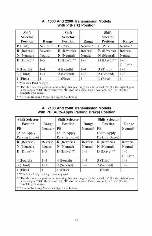
All 1000 And 2200 Transmission ModelsWith P (Park) Position
ShiftSelectorPosition Range
ShiftSelectorPosition Range
ShiftSelectorPosition Range
P (Park) Neutral* P (Park) Neutral* P (Park) Neutral*R (Reverse) Reverse R (Reverse) Reverse R (Reverse) ReverseN (Neutral) Neutral N (Neutral) Neutral N (Neutral) NeutralD (Drive)** 1–5 D (Drive)** 1–5 D (Drive)** 1–5
(1–4)***
4 (Fourth) 1–4 4 (Fourth) 1–4 3 (Third) 1–33 (Third) 1–3 2 (Second) 1–2 2 (Second) 1–21 (First) 1 1 (First) 1 1 (First) 1* With Park Pawl engaged
** The shift selector position representing this gear range may be labeled “5” (for the highest gearin the range), “OD” (for Overdrive), “D” (for the normal Drive position), or “1–5” (for thecomplete gear range)
*** 1–4 in Trailering Mode or 4-Speed Calibration
All 2100 And 2500 Transmission ModelsWith PB (Auto-Apply Parking Brake) Position
Shift SelectorPosition Range
Shift SelectorPosition Range
Shift SelectorPosition Range
PB(Auto-ApplyParking Brake)
Neutral* PB(Auto-ApplyParking Brake)
Neutral* PB(Auto-ApplyParking Brake)
Neutral*
R (Reverse) Reverse R (Reverse) Reverse R (Reverse) ReverseN (Neutral) Neutral N (Neutral) Neutral N (Neutral) NeutralD (Drive)** 1–5 D (Drive)** 1–5 D (Drive)** 1–5
(1–4)***
4 (Fourth) 1–4 4 (Fourth) 1–4 3 (Third) 1–33 (Third) 1–3 2 (Second) 1–2 2 (Second) 1–21 (First) 1 1 (First) 1 1 (First) 1* With Auto-Apply Parking Brake engaged
** The shift selector position representing this gear range may be labeled “5” (for the highest gearin the range), “OD” (for Overdrive), “D” (for the normal Drive position), or “1–5” (for thecomplete gear range).
*** 1–4 in Trailering Mode or 4-Speed Calibration
15
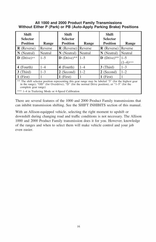
All 1000 and 2000 Product Family TransmissionsWithout Either P (Park) or PB (Auto-Apply Parking Brake) Positions
ShiftSelectorPosition Range
ShiftSelectorPosition Range
ShiftSelectorPosition Range
R (Reverse) Reverse R (Reverse) Reverse R (Reverse) ReverseN (Neutral) Neutral N (Neutral) Neutral N (Neutral) NeutralD (Drive)** 1–5 D (Drive)** 1–5 D (Drive)** 1–5
(1–4)***
4 (Fourth) 1–4 4 (Fourth) 1–4 3 (Third) 1–33 (Third) 1–3 2 (Second) 1–2 2 (Second) 1–21 (First) 1 1 (First) 1 1 (First) 1** The shift selector position representing this gear range may be labeled “5” (for the highest gear
in the range), “OD” (for Overdrive), “D” (for the normal Drive position), or “1–5” (for thecomplete gear range)
*** 1–4 in Trailering Mode or 4-Speed Calibration
There are several features of the 1000 and 2000 Product Family transmissions thatcan inhibit transmission shifting. See the SHIFT INHIBITS section of this manual.
With an Allison-equipped vehicle, selecting the right moment to upshift ordownshift during changing road and traffic conditions is not necessary. The Allison1000 and 2000 Product Family transmission does it for you. However, knowledgeof the ranges and when to select them will make vehicle control and your jobeven easier.
16
RANGE SELECTION—ALL 1000 AND 2200 TRANSMISSIONMODELS WITH PARK PAWL AND P (PARK) POSITION
ALL 1000 AND 2200 TRANSMISSION MODELS WITH P (PARK)POSITION
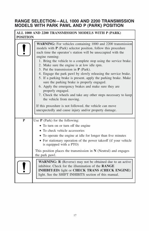
WARNING: For vehicles containing 1000 and 2200 transmissionmodels with P (Park) selector position, follow this procedureeach time the operator’s station will be unoccupied with theengine running:
1. Bring the vehicle to a complete stop using the service brake.2. Make sure the engine is at low idle rpm.3. Put the transmission in P (Park).4. Engage the park pawl by slowly releasing the service brake.5. If a parking brake is present, apply the parking brake. Make
sure the parking brake is properly engaged.6. Apply the emergency brakes and make sure they are
properly engaged.7. Chock the wheels and take any other steps necessary to keep
the vehicle from moving.
If this procedure is not followed, the vehicle can moveunexpectedly and cause injury and/or property damage.
P Use P (Park) for the following:
• To turn on or turn off the engine
• To check vehicle accessories
• To operate the engine at idle for longer than five minutes
• For stationary operation of the power takeoff (if your vehicleis equipped with a PTO)
This position places the transmission in N (Neutral) and engagesthe park pawl.
WARNING: R (Reverse) may not be obtained due to an activeinhibitor. Check for the illumination of the RANGEINHIBIT(ED) light or CHECK TRANS (CHECK ENGINE)light. See the SHIFT INHIBITS section of this manual.
17
ALL 1000 AND 2200 TRANSMISSION MODELS WITH P (PARK)POSITION
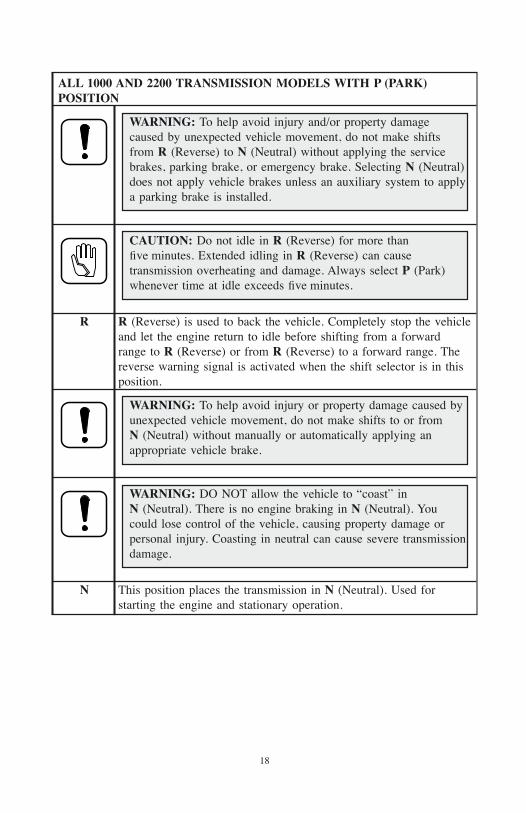
WARNING: To help avoid injury and/or property damagecaused by unexpected vehicle movement, do not make shiftsfrom R (Reverse) to N (Neutral) without applying the servicebrakes, parking brake, or emergency brake. Selecting N (Neutral)does not apply vehicle brakes unless an auxiliary system to applya parking brake is installed.
CAUTION: Do not idle in R (Reverse) for more thanfive minutes. Extended idling in R (Reverse) can causetransmission overheating and damage. Always select P (Park)whenever time at idle exceeds five minutes.
R R (Reverse) is used to back the vehicle. Completely stop the vehicleand let the engine return to idle before shifting from a forwardrange to R (Reverse) or from R (Reverse) to a forward range. Thereverse warning signal is activated when the shift selector is in thisposition.
WARNING: To help avoid injury or property damage caused byunexpected vehicle movement, do not make shifts to or fromN (Neutral) without manually or automatically applying anappropriate vehicle brake.
WARNING: DO NOT allow the vehicle to “coast” inN (Neutral). There is no engine braking in N (Neutral). Youcould lose control of the vehicle, causing property damage orpersonal injury. Coasting in neutral can cause severe transmissiondamage.
N This position places the transmission in N (Neutral). Used forstarting the engine and stationary operation.
18
ALL 1000 AND 2200 TRANSMISSION MODELS WITH P (PARK)POSITION
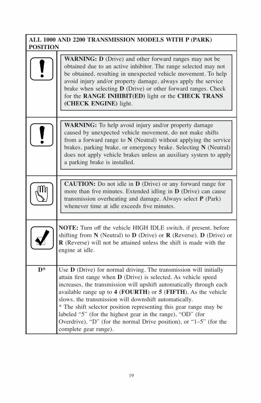
WARNING: D (Drive) and other forward ranges may not beobtained due to an active inhibitor. The range selected may notbe obtained, resulting in unexpected vehicle movement. To helpavoid injury and/or property damage, always apply the servicebrake when selecting D (Drive) or other forward ranges. Checkfor the RANGE INHIBIT(ED) light or the CHECK TRANS(CHECK ENGINE) light.
WARNING: To help avoid injury and/or property damagecaused by unexpected vehicle movement, do not make shiftsfrom a forward range to N (Neutral) without applying the servicebrakes, parking brake, or emergency brake. Selecting N (Neutral)does not apply vehicle brakes unless an auxiliary system to applya parking brake is installed.
CAUTION: Do not idle in D (Drive) or any forward range formore than five minutes. Extended idling in D (Drive) can causetransmission overheating and damage. Always select P (Park)whenever time at idle exceeds five minutes.
NOTE: Turn off the vehicle HIGH IDLE switch, if present, beforeshifting from N (Neutral) to D (Drive) or R (Reverse). D (Drive) orR (Reverse) will not be attained unless the shift is made with theengine at idle.
D* Use D (Drive) for normal driving. The transmission will initiallyattain first range when D (Drive) is selected. As vehicle speedincreases, the transmission will upshift automatically through eachavailable range up to 4 (FOURTH) or 5 (FIFTH). As the vehicleslows, the transmission will downshift automatically.* The shift selector position representing this gear range may belabeled “5” (for the highest gear in the range), “OD” (forOverdrive), “D” (for the normal Drive position), or “1–5” (for thecomplete gear range).
19
ALL 1000 AND 2200 TRANSMISSION MODELS WITH P (PARK)POSITION
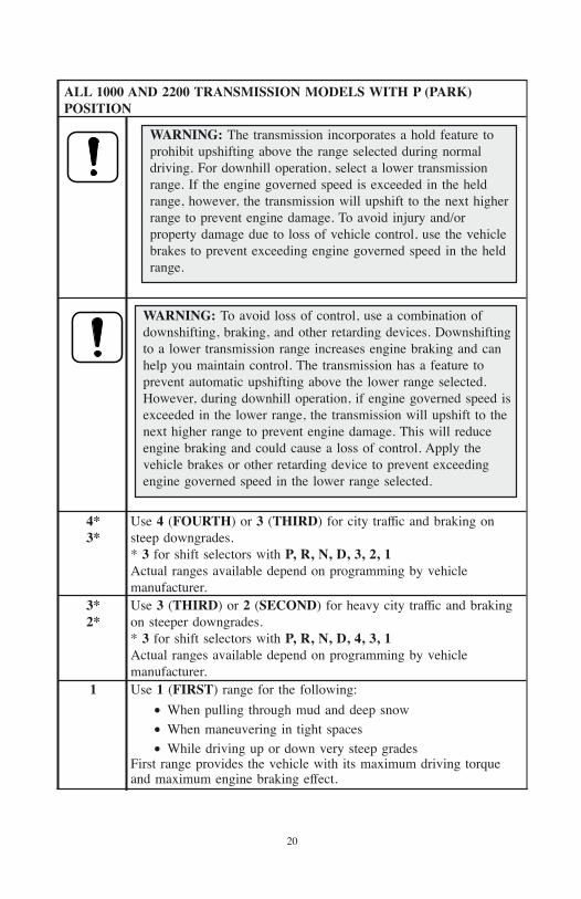
WARNING: The transmission incorporates a hold feature toprohibit upshifting above the range selected during normaldriving. For downhill operation, select a lower transmissionrange. If the engine governed speed is exceeded in the heldrange, however, the transmission will upshift to the next higherrange to prevent engine damage. To avoid injury and/orproperty damage due to loss of vehicle control, use the vehiclebrakes to prevent exceeding engine governed speed in the heldrange.
WARNING: To avoid loss of control, use a combination ofdownshifting, braking, and other retarding devices. Downshiftingto a lower transmission range increases engine braking and canhelp you maintain control. The transmission has a feature toprevent automatic upshifting above the lower range selected.However, during downhill operation, if engine governed speed isexceeded in the lower range, the transmission will upshift to thenext higher range to prevent engine damage. This will reduceengine braking and could cause a loss of control. Apply thevehicle brakes or other retarding device to prevent exceedingengine governed speed in the lower range selected.
4*3*
Use 4 (FOURTH) or 3 (THIRD) for city traffic and braking onsteep downgrades.* 3 for shift selectors with P, R, N, D, 3, 2, 1Actual ranges available depend on programming by vehiclemanufacturer.
3*2*
Use 3 (THIRD) or 2 (SECOND) for heavy city traffic and brakingon steeper downgrades.* 3 for shift selectors with P, R, N, D, 4, 3, 1Actual ranges available depend on programming by vehiclemanufacturer.
1 Use 1 (FIRST) range for the following:
• When pulling through mud and deep snow
• When maneuvering in tight spaces
• While driving up or down very steep gradesFirst range provides the vehicle with its maximum driving torqueand maximum engine braking effect.
20
RANGE SELECTION—ALL 2100 AND 2500 TRANSMISSIONMODELS WITH PB (AUTO-APPLY PARKING BRAKE)POSITION
ALL 2100 AND 2500 TRANSMISSION MODELS WITH PB (AUTO-APPLY PARKING BRAKE) POSITION
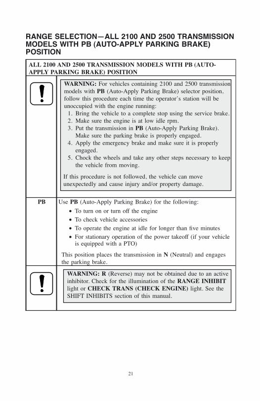
WARNING: For vehicles containing 2100 and 2500 transmissionmodels with PB (Auto-Apply Parking Brake) selector position,follow this procedure each time the operator’s station will beunoccupied with the engine running:
1. Bring the vehicle to a complete stop using the service brake.2. Make sure the engine is at low idle rpm.3. Put the transmission in PB (Auto-Apply Parking Brake).
Make sure the parking brake is properly engaged.4. Apply the emergency brake and make sure it is properly
engaged.5. Chock the wheels and take any other steps necessary to keep
the vehicle from moving.
If this procedure is not followed, the vehicle can moveunexpectedly and cause injury and/or property damage.
PB Use PB (Auto-Apply Parking Brake) for the following:
• To turn on or turn off the engine
• To check vehicle accessories
• To operate the engine at idle for longer than five minutes
• For stationary operation of the power takeoff (if your vehicleis equipped with a PTO)
This position places the transmission in N (Neutral) and engagesthe parking brake.
WARNING: R (Reverse) may not be obtained due to an activeinhibitor. Check for the illumination of the RANGE INHIBITlight or CHECK TRANS (CHECK ENGINE) light. See theSHIFT INHIBITS section of this manual.
21
ALL 2100 AND 2500 TRANSMISSION MODELS WITH PB (AUTO-APPLY PARKING BRAKE) POSITION
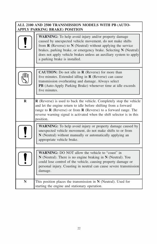
WARNING: To help avoid injury and/or property damagecaused by unexpected vehicle movement, do not make shiftsfrom R (Reverse) to N (Neutral) without applying the servicebrakes, parking brake, or emergency brake. Selecting N (Neutral)does not apply vehicle brakes unless an auxiliary system to applya parking brake is installed.
CAUTION: Do not idle in R (Reverse) for more thanfive minutes. Extended idling in R (Reverse) can causetransmission overheating and damage. Always selectPB (Auto-Apply Parking Brake) whenever time at idle exceedsfive minutes.
R R (Reverse) is used to back the vehicle. Completely stop the vehicleand let the engine return to idle before shifting from a forwardrange to R (Reverse) or from R (Reverse) to a forward range. Thereverse warning signal is activated when the shift selector is in thisposition.
WARNING: To help avoid injury or property damage caused byunexpected vehicle movement, do not make shifts to or fromN (Neutral) without manually or automatically applying anappropriate vehicle brake.
WARNING: DO NOT allow the vehicle to “coast” inN (Neutral). There is no engine braking in N (Neutral). Youcould lose control of the vehicle, causing property damage orpersonal injury. Coasting in neutral can cause severe transmissiondamage.
N This position places the transmission in N (Neutral). Used forstarting the engine and stationary operation.
22

ALL 2100 AND 2500 TRANSMISSION MODELS WITH PB (AUTO-APPLY PARKING BRAKE) POSITION
WARNING: D (Drive) and other forward ranges may not beobtained due to an active inhibitor. The range selected may notbe obtained, resulting in unexpected vehicle movement. To helpavoid injury and/or property damage, always apply the servicebrake when selecting D (Drive) or other forward ranges. Checkfor the RANGE INHIBIT(ED) light or the CHECK TRANS(CHECK ENGINE) light.
WARNING: To help avoid injury and/or property damagecaused by unexpected vehicle movement, do not make shiftsfrom a forward range to N (Neutral) without applying the servicebrakes, parking brake, or emergency brake. Selecting N (Neutral)does not apply vehicle brakes unless an auxiliary system to applya parking brake is installed.
CAUTION: Do not idle in D (Drive) or any forward range formore than five minutes. Extended idling in D (Drive) can causetransmission overheating and damage. Always selectPB (Auto-Apply Parking Brake) whenever time at idle exceedsfive minutes.
NOTE: Turn off the vehicle HIGH IDLE switch, if present, beforeshifting from N (Neutral) to D (Drive) or R (Reverse). D (Drive) orR (Reverse) will not be attained unless the shift is made with theengine at idle.
D* Use D (Drive) for normal driving. The transmission will initiallyattain first range when D (Drive) is selected. As vehicle speedincreases, the transmission will upshift automatically through eachavailable range up to 4 (FOURTH) or 5 (FIFTH). As the vehicleslows, the transmission will downshift automatically.* The shift selector position representing this gear range may belabeled “5” (for the highest gear in the range), “OD” (forOverdrive), “D” (for the normal Drive position), or “1–5” (for thecomplete gear range).
23
ALL 2100 AND 2500 TRANSMISSION MODELS WITH PB (AUTO-APPLY PARKING BRAKE) POSITION
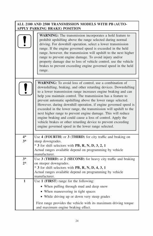
WARNING: The transmission incorporates a hold feature toprohibit upshifting above the range selected during normaldriving. For downhill operation, select a lower transmissionrange. If the engine governed speed is exceeded in the heldrange, however, the transmission will upshift to the next higherrange to prevent engine damage. To avoid injury and/orproperty damage due to loss of vehicle control, use the vehiclebrakes to prevent exceeding engine governed speed in the heldrange.
WARNING: To avoid loss of control, use a combination ofdownshifting, braking, and other retarding devices. Downshiftingto a lower transmission range increases engine braking and canhelp you maintain control. The transmission has a feature toprevent automatic upshifting above the lower range selected.However, during downhill operation, if engine governed speed isexceeded in the lower range, the transmission will upshift to thenext higher range to prevent engine damage. This will reduceengine braking and could cause a loss of control. Apply thevehicle brakes or other retarding device to prevent exceedingengine governed speed in the lower range selected.
4*3*
Use 4 (FOURTH) or 3 (THIRD) for city traffic and braking onsteep downgrades.* 3 for shift selectors with PB, R, N, D, 3, 2, 1Actual ranges available depend on programming by vehiclemanufacturer.
3*2*
Use 3 (THIRD) or 2 (SECOND) for heavy city traffic and brakingon steeper downgrades.* 3 for shift selectors with PB, R, N, D, 4, 3, 1Actual ranges available depend on programming by vehiclemanufacturer.
1 Use 1 (FIRST) range for the following:
• When pulling through mud and deep snow
• When maneuvering in tight spaces
• While driving up or down very steep grades
First range provides the vehicle with its maximum driving torqueand maximum engine braking effect.
24
RANGE SELECTION—ALL 1000 AND 2000 PRODUCTFAMILY TRANSMISSIONS WITHOUT EITHER P (PARK) ORPB (AUTO-APPLY PARKING BRAKE) POSITIONS
ALL 1000 AND 2000 PRODUCT FAMILY TRANSMISSIONS WITHOUTEITHER P (PARK) OR PB (AUTO-APPLY PARKING BRAKE)POSITIONS
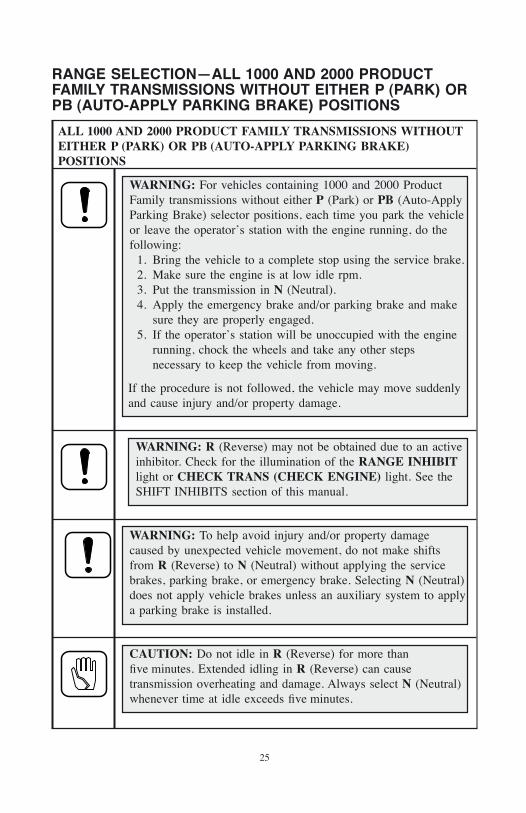
WARNING: For vehicles containing 1000 and 2000 ProductFamily transmissions without either P (Park) or PB (Auto-ApplyParking Brake) selector positions, each time you park the vehicleor leave the operator’s station with the engine running, do thefollowing:
1. Bring the vehicle to a complete stop using the service brake.2. Make sure the engine is at low idle rpm.3. Put the transmission in N (Neutral).4. Apply the emergency brake and/or parking brake and make
sure they are properly engaged.5. If the operator’s station will be unoccupied with the engine
running, chock the wheels and take any other stepsnecessary to keep the vehicle from moving.
If the procedure is not followed, the vehicle may move suddenlyand cause injury and/or property damage.
WARNING: R (Reverse) may not be obtained due to an activeinhibitor. Check for the illumination of the RANGE INHIBITlight or CHECK TRANS (CHECK ENGINE) light. See theSHIFT INHIBITS section of this manual.
WARNING: To help avoid injury and/or property damagecaused by unexpected vehicle movement, do not make shiftsfrom R (Reverse) to N (Neutral) without applying the servicebrakes, parking brake, or emergency brake. Selecting N (Neutral)does not apply vehicle brakes unless an auxiliary system to applya parking brake is installed.
CAUTION: Do not idle in R (Reverse) for more thanfive minutes. Extended idling in R (Reverse) can causetransmission overheating and damage. Always select N (Neutral)whenever time at idle exceeds five minutes.
25
ALL 1000 AND 2000 PRODUCT FAMILY TRANSMISSIONS WITHOUTEITHER P (PARK) OR PB (AUTO-APPLY PARKING BRAKE)POSITIONS
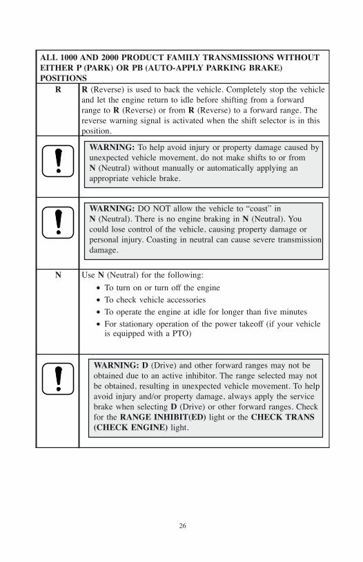
R R (Reverse) is used to back the vehicle. Completely stop the vehicleand let the engine return to idle before shifting from a forwardrange to R (Reverse) or from R (Reverse) to a forward range. Thereverse warning signal is activated when the shift selector is in thisposition.
WARNING: To help avoid injury or property damage caused byunexpected vehicle movement, do not make shifts to or fromN (Neutral) without manually or automatically applying anappropriate vehicle brake.
WARNING: DO NOT allow the vehicle to “coast” inN (Neutral). There is no engine braking in N (Neutral). Youcould lose control of the vehicle, causing property damage orpersonal injury. Coasting in neutral can cause severe transmissiondamage.
N Use N (Neutral) for the following:
• To turn on or turn off the engine
• To check vehicle accessories
• To operate the engine at idle for longer than five minutes
• For stationary operation of the power takeoff (if your vehicleis equipped with a PTO)
WARNING: D (Drive) and other forward ranges may not beobtained due to an active inhibitor. The range selected may notbe obtained, resulting in unexpected vehicle movement. To helpavoid injury and/or property damage, always apply the servicebrake when selecting D (Drive) or other forward ranges. Checkfor the RANGE INHIBIT(ED) light or the CHECK TRANS(CHECK ENGINE) light.
26
ALL 1000 AND 2000 PRODUCT FAMILY TRANSMISSIONS WITHOUTEITHER P (PARK) OR PB (AUTO-APPLY PARKING BRAKE)POSITIONS
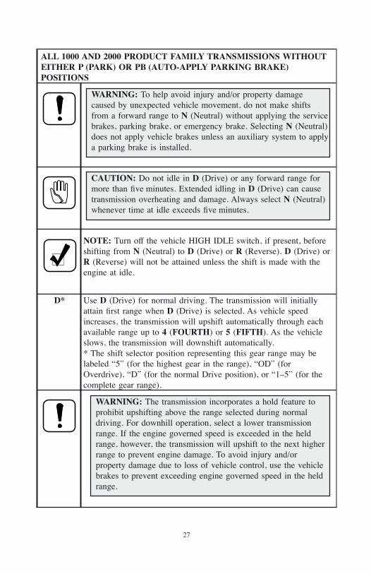
WARNING: To help avoid injury and/or property damagecaused by unexpected vehicle movement, do not make shiftsfrom a forward range to N (Neutral) without applying the servicebrakes, parking brake, or emergency brake. Selecting N (Neutral)does not apply vehicle brakes unless an auxiliary system to applya parking brake is installed.
CAUTION: Do not idle in D (Drive) or any forward range formore than five minutes. Extended idling in D (Drive) can causetransmission overheating and damage. Always select N (Neutral)whenever time at idle exceeds five minutes.
NOTE: Turn off the vehicle HIGH IDLE switch, if present, beforeshifting from N (Neutral) to D (Drive) or R (Reverse). D (Drive) orR (Reverse) will not be attained unless the shift is made with theengine at idle.
D* Use D (Drive) for normal driving. The transmission will initiallyattain first range when D (Drive) is selected. As vehicle speedincreases, the transmission will upshift automatically through eachavailable range up to 4 (FOURTH) or 5 (FIFTH). As the vehicleslows, the transmission will downshift automatically.* The shift selector position representing this gear range may belabeled “5” (for the highest gear in the range), “OD” (forOverdrive), “D” (for the normal Drive position), or “1–5” (for thecomplete gear range).
WARNING: The transmission incorporates a hold feature toprohibit upshifting above the range selected during normaldriving. For downhill operation, select a lower transmissionrange. If the engine governed speed is exceeded in the heldrange, however, the transmission will upshift to the next higherrange to prevent engine damage. To avoid injury and/orproperty damage due to loss of vehicle control, use the vehiclebrakes to prevent exceeding engine governed speed in the heldrange.
27
ALL 1000 AND 2000 PRODUCT FAMILY TRANSMISSIONS WITHOUTEITHER P (PARK) OR PB (AUTO-APPLY PARKING BRAKE)POSITIONS
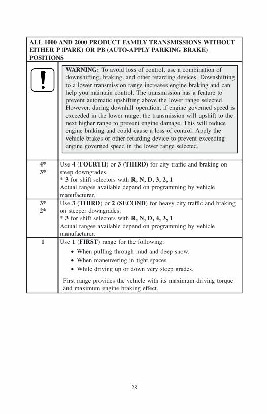
WARNING: To avoid loss of control, use a combination ofdownshifting, braking, and other retarding devices. Downshiftingto a lower transmission range increases engine braking and canhelp you maintain control. The transmission has a feature toprevent automatic upshifting above the lower range selected.However, during downhill operation, if engine governed speed isexceeded in the lower range, the transmission will upshift to thenext higher range to prevent engine damage. This will reduceengine braking and could cause a loss of control. Apply thevehicle brakes or other retarding device to prevent exceedingengine governed speed in the lower range selected.
4*3*
Use 4 (FOURTH) or 3 (THIRD) for city traffic and braking onsteep downgrades.* 3 for shift selectors with R, N, D, 3, 2, 1Actual ranges available depend on programming by vehiclemanufacturer.
3*2*
Use 3 (THIRD) or 2 (SECOND) for heavy city traffic and brakingon steeper downgrades.* 3 for shift selectors with R, N, D, 4, 3, 1Actual ranges available depend on programming by vehiclemanufacturer.
1 Use 1 (FIRST) range for the following:
• When pulling through mud and deep snow.
• When maneuvering in tight spaces.
• While driving up or down very steep grades.
First range provides the vehicle with its maximum driving torqueand maximum engine braking effect.
28
PREVENT MAJOR PROBLEMSMinor problems can be kept from becoming major problems if you notify yourservice management or an Allison Transmission distributor or dealer when any ofthese conditions occur:
• Shifting feels abnormal.
• Transmission leaks fluid.
• Unusual transmission-related sounds (changes in sound caused by normalengine thermostatic fan cycling, while climbing a long grade with a heavyload, have been mistaken for transmission-related sounds).
• CHECK TRANS light or RANGE INHIBIT(ED) light comes onfrequently.
TURNING THE VEHICLE ON/OFFBefore turning on or off the engine, the driver must verify that the service brake isengaged and one of the following ranges has been selected and engaged:
• P (Park)
• PB (Auto-Apply Parking Brake)
• N (Neutral) if P (Park) or PB (Auto-Apply Parking Brake) is not available
NOTE: The vehicle should not start unless these ranges have beenselected. If the vehicle starts in any other range, seek serviceimmediately.
Transmission operation at cold ambient temperatures may require preheating orthe use of a lower viscosity transmission fluid. See the FLUID RECOMMENDA-TIONS section in this manual.
Even when the engine is warm and capable of full-throttle output, the transmissionshould not be taken out of P (Park), PB (Auto-Apply Parking Brake), orN (Neutral) for at least thirty seconds to allow for buildup of transmission fluidpressure.
DRIVING TIPS
29
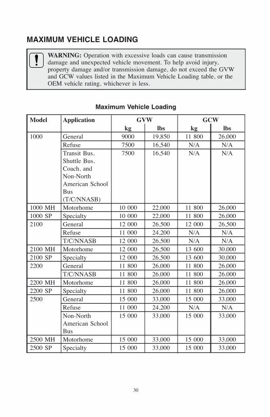
MAXIMUM VEHICLE LOADING
WARNING: Operation with excessive loads can cause transmissiondamage and unexpected vehicle movement. To help avoid injury,property damage and/or transmission damage, do not exceed the GVWand GCW values listed in the Maximum Vehicle Loading table, or theOEM vehicle rating, whichever is less.
Maximum Vehicle Loading
Model Application GVW GCWkg lbs kg lbs
1000 General 9000 19,850 11 800 26,000Refuse 7500 16,540 N/A N/ATransit Bus,Shuttle Bus,Coach, andNon-NorthAmerican SchoolBus(T/C/NNASB)
7500 16,540 N/A N/A
1000 MH Motorhome 10 000 22,000 11 800 26,0001000 SP Specialty 10 000 22,000 11 800 26,0002100 General 12 000 26,500 12 000 26,500
Refuse 11 000 24,200 N/A N/AT/C/NNASB 12 000 26,500 N/A N/A
2100 MH Motorhome 12 000 26,500 13 600 30,0002100 SP Specialty 12 000 26,500 13 600 30,0002200 General 11 800 26,000 11 800 26,000
T/C/NNASB 11 800 26,000 11 800 26,0002200 MH Motorhome 11 800 26,000 11 800 26,0002200 SP Specialty 11 800 26,000 11 800 26,0002500 General 15 000 33,000 15 000 33,000
Refuse 11 000 24,200 N/A N/ANon-NorthAmerican SchoolBus
15 000 33,000 15 000 33,000
2500 MH Motorhome 15 000 33,000 15 000 33,0002500 SP Specialty 15 000 33,000 15 000 33,000
30
ACCELERATOR CONTROL
WARNING: To avoid injury or property damage caused by suddenmovement of the vehicle, do not make shifts from N (Neutral) to aforward range or R (Reverse) when the throttle is open. The vehicle willlurch forward or rearward and the transmission can be damaged. Avoidthis condition by making shifts from N (Neutral) to a forward range orR (Reverse) only when the throttle is closed and service brakes areapplied.
The position of the accelerator pedal influences when automatic shifting occurs.When the pedal is fully depressed, upshifts will occur automatically at high enginespeeds. A partially depressed position of the pedal will cause the upshifts to occurat lower engine speeds. An electronic throttle position signal tells the TCM howmuch the operator has depressed the pedal. Excessive throttle position may inhibitthe directional shift.
PRIMARY/SECONDARY SHIFT SCHEDULESThe points at which shifts occur depend upon predetermined speeds and otheroperating conditions. A transmission “shift calibration” includes several sets ofshift points which may be used according to current or anticipated operatingconditions. Some shift schedules may be inhibited as a result of operatingconditions, such as engine or transmission fluid temperature. Shift schedules maybe changed through selection of a remote (usually dash-mounted) switch—whichis typically associated with a change in anticipated vehicle operation.
The TCM includes the capacity for two separate and distinct shift calibrations(customer-selectable), one for use in primary mode of operation and one insecondary mode.
• Primary—This shift schedule is typically used for all normal vehicleoperations.
• Secondary—This is an alternate shift schedule that the TCM uses uponrequest. Not all vehicles will be equipped with a secondary shift schedule.The request can be interlocked with a vehicle component, or beoperator-controlled using a dash-mounted switch.
Your vehicle may have a dash-mounted light that illuminates when the secondarymode is active.
KICKDOWNSome vehicles have a “kickdown” feature that allows the operator to choosebetween an “Economy” primary shift schedule and “Performance” secondary shiftschedule. The throttle pedal will have a detent feel when full-throttle is achieved
31
using “Economy” shift points. When the operator “steps through” this detent, thefunction is activated and “Performance” shift points are achieved.
OUTPUT SPEED INDICATORYour vehicle may contain a light or other indicator that is activated when a presetoutput speed has been exceeded in the vehicle, transmission, or auxiliaryequipment. The output speed may occur in either the forward or reverse direction.This indicator may be used to alert the operator that a specific overspeed conditionhas occurred or to indicate that a minimum or maximum operating speed wasattained.
DIAGNOSTIC CODESSee detailed information in the DIAGNOSTICS section.
RANGE INHIBIT(ED) LIGHTThe red or amber RANGE INHIBIT(ED) warning light is located on or near theshift selector. The purpose of this indicator is to alert the operator thattransmission operation is being inhibited and that range shifts being requested bythe operator may not occur. When certain operating conditions are detected by theTCM, the controls will command the transmission to be locked in the rangecurrently in use. If the torque converter clutch is applied when the condition isdetected, the clutch will be disengaged concurrently with the activation of theRANGE INHIBIT(ED) light.
Each time the engine is started, the RANGE INHIBIT(ED) light will illuminate,then turn off after two seconds. If the light does not illuminate during ignition, orif the light remains on after ignition, the transmission system should be checkedimmediately.
For the conditions under which shift inhibits occur, see the SHIFT INHIBITSsection in this manual.
CHECK TRANS OR MALFUNCTION INDICATOR LIGHTThe red or amber CHECK TRANS light or Malfunction Indicator Light (MIL) islocated on the dash panel. A MIL is present on vehicles that meet industry OnBoard Diagnostics II (OBD II) requirements. A CHECK TRANS light is presenton vehicles not subject to industry OBD II requirements.
Each time the engine is started, the CHECK TRANS light or MIL willilluminate, then turn off after two seconds. If the light does not illuminate duringignition, or if the light remains on after ignition, the transmission system shouldbe checked immediately.
32
Illumination of the CHECK TRANS light or MIL at any time after start-upindicates that a problem has been detected. The TCM will register a diagnosticcode and shifts may be restricted. Depending upon the severity of the problem,operation may continue in order to reach service assistance. The TCM may notrespond to shift selector requests since upshifts and downshifts may be restrictedand direction changes may not occur.
Illumination of the CHECK TRANS light or MIL at any time after start-up mayindicate a problem with the engine or transmission Refer to the DIAGNOSTICSsection for more information on diagnostic codes.
SHIFT INHIBITSThe transmission control system will inhibit shifting to protect the transmissionfrom some types of abusive operation, in response to diagnostic trouble codes, andto satisfy transmission feature/option requirements. These shift inhibits fall withinthe following types:
• Above-idle neutral-to-range shifts
• Forward/reverse directional shifts
• Transmission problems
• Auxiliary equipment operation
Above-Idle Neutral-to-Range Shifts.
WARNING: To avoid injury or property damage caused by suddenmovement of the vehicle, do not make shifts from N (Neutral) to aforward range or R (Reverse) when the throttle is open. The vehicle willlurch forward or rearward and the transmission can be damaged. Avoidthis condition by making shifts from N (Neutral) to a forward range orR (Reverse) only when the throttle is closed and service brakes areapplied.
Above-idle (greater than 900 rpm) shifts from N (Neutral) to R (Reverse) orN (Neutral) to a forward range are normally inhibited (except in emergencyvehicles or some other type of specialized equipment).
When these shifts are inhibited, the RANGE INHIBIT(ED) light will illuminate.See the RANGE INHIBIT(ED) LIGHT section in this manual for furtherinformation.
33
Forward/Reverse Directional Shifts.
WARNING: To avoid injury or property damage caused by suddenmovement of the vehicle, do not make shifts from N (Neutral) to aforward range or R (Reverse) when the throttle is open. The vehicle willlurch forward or rearward and the transmission can be damaged. Avoidthis condition by making shifts from N (Neutral) to a forward range orR (Reverse) only when the throttle is closed and service brakes areapplied.
Forward/reverse directional changes are typically not permitted if appreciableoutput shaft speed is detected.
When these shifts are inhibited, the RANGE INHIBIT(ED) light will illuminate.See the RANGE INHIBIT(ED) LIGHT section in this manual for furtherinformation.
Transmission Problems. Lights such as the RANGE INHIBIT(ED), CHECKTRANS, or Malfunction Indicator Light (MIL), and a flashing PRNDL displaywill be illuminated when the transmission detects a functional concern.
An illuminated RANGE INHIBIT(ED) light or a flashing PRNDL displayindicates that the Transmission Control Module (TCM) has detected a conditionwhere directional shifts are not allowed to be made. This inhibited state can be aself-clearing or lasting condition depending on the amount of time the condition ispresent.
The following conditions may cause an inhibited state:
• Engine speed too high
• Throttle percentage incorrect
• Output speed movement
See the RANGE INHIBIT(ED) LIGHT or CHECK TRANS OR MALFUNCTIONINDICATOR LIGHT section in this manual for further information.
Depending on the severity of the Diagnostic Trouble Code (DTC), thetransmission may default to an operating state predefined by the TCM such as“Limp Home”. “Limp Home” will temporarily limit normal transmission operationuntil the vehicle can be driven to a service location and the severity of theproblem is determined. The transmission will remain in the “Limp Home” stateuntil the problem has been corrected. Following an engine restart, the transmissionmay obtain THIRD, NEUTRAL, or REVERSE. Reference the Sales andService Directory (SA2229EN) for the current listing of Allison Transmissionauthorized distributor and service dealers.
See the RANGE INHIBIT(ED) LIGHT and SHIFT INHIBITS sections in thismanual for further information.
34
Auxiliary Equipment Operation. The TCM will prevent shifts from P (Park),PB (Auto-Apply Parking Brake), or N (Neutral)-to-range when auxiliaryequipment is in operation (e.g., a wheelchair lift). For some vehicles such asbuses, shifts from P (Park), PB (Auto-Apply Parking Brake), orN (Neutral)-to-range will be prevented unless the brake pedal is depressed.
USING THE ENGINE TO SLOW THE VEHICLE
WARNING: The transmission incorporates a hold feature to prohibitupshifting above the range selected during normal driving. For downhilloperation, select a lower transmission range. If the engine governedspeed is exceeded in the held range, however, the transmission willupshift to the next higher range to prevent engine damage. To avoidinjury and/or property damage due to loss of vehicle control, use thevehicle brakes to prevent exceeding engine governed speed in the heldrange.
WARNING: To avoid loss of control, use a combination ofdownshifting, braking, and other retarding devices. Downshifting to alower transmission range increases engine braking and can help youmaintain control. The transmission has a feature to prevent automaticupshifting above the lower range selected. However, during downhilloperation, if engine governed speed is exceeded in the lower range, thetransmission will upshift to the next higher range to prevent enginedamage. This will reduce engine braking and could cause a loss ofcontrol. Apply the vehicle brakes or other retarding device to preventexceeding engine governed speed in the lower range selected.
To use the engine as a braking force, select the next lower range. If the vehicle isexceeding the maximum speed for this range, use the service brakes and/or otherretarding devices to slow the vehicle. When a lower speed is reached, the TCMwill automatically downshift the transmission. Engine braking provides goodspeed control for going down grades. When the vehicle is heavily loaded, or thegrade is steep, it may be desirable to preselect a lower range before reaching thegrade. If the engine-governed speed is exceeded, the transmission will upshiftautomatically to the next range.
CAUTION: Using the engine brake on wet or slippery roads may causeloss of traction on the drive wheels—your vehicle may slide out ofcontrol. To help avoid injury or property damage, turn the engine brakeenable to OFF when driving on wet or slippery roads.
35
RANGE PRESELECTIONRange preselection means selecting a lower range to match driving conditions youencounter or expect to encounter. Learning to take advantage of preselected shiftswill give you better control on slick or icy roads and on downgrades.Downshifting to a lower range increases engine braking. The selection of a lowerrange often prevents cycling between that range and the next higher range on aseries of short up-and-down hills.
NOTE: Preselecting during normal operation may result in reduced fueleconomy.
Manual range downshifts will not occur until a calibration value of output speed isreached. When a range downshift is manually selected and the transmission outputspeed is above the calibration value, the transmission will stay in the range it wasin even though a lower range was requested. Apply the vehicle service brakes orsome retarding device to reduce the transmission output speed to the calibrationvalue and then the shift to the lower range will occur.
Two shift schedules are used with range preselection: hold upshift and preselectdownshift.
Hold Upshift. This shift schedule keeps the transmission from shifting above theselected range. This shift schedule permits upshifts to occur if an engineoverspeed condition could result by the transmission remaining (by operatorselection) in a range lower than its highest range. When the hold feature isactivated, transmission upshift points occur at engine speeds which are higher thannormal upshifts in order to “hold” the transmission from upshifting beyond thecurrent range.
WARNING: The transmission incorporates a hold feature to prohibitupshifting above the range selected during normal driving. For downhilloperation, select a lower transmission range. If the engine governedspeed is exceeded in the held range, however, the transmission willupshift to the next higher range to prevent engine damage. To avoidinjury and/or property damage due to loss of vehicle control, use thevehicle brakes to prevent exceeding engine governed speed in the heldrange.
Preselect Downshift. This shift schedule is used when the driver preselects alower range. The operator may preselect any range below D (Drive) on the shiftselector at any time. When a range has been “preselected” in this manner, shiftpoints to and from ranges above the preselected range are higher than the normalshift points. The transmission will downshift when an engine overspeed conditionwill not result after the shift. Shifts below the preselected range are not affected.
36
REVERSEPutting the transmission into R (Reverse) may activate vehicle backup lightsand/or reverse warning devices.
To achieve REVERSE range in some European transit and tour buses, aninstrument panel-mounted switch must be pressed simultaneously with theR (Reverse) shift selector button.
REFUSE PACKER STEP SWITCHWhen personnel are on the rear step of a refuse packer, the transmission willoperate in FIRST and NEUTRAL only.
• An operator request to upshift beyond FIRST or to shift to REVERSE isignored by the TCM.
• If the transmission is in REVERSE, the TCM will cause the transmissionto shift to NEUTRAL.
• If the transmission is in a forward range higher than FIRST, the TCM willinvoke “preselect downshifts” until FIRST is attained.
TWO-SPEED AXLE (Some General TransmissionApplications)The two-speed axle may be shifted while the vehicle is moving. However, theaxle or vehicle manufacturer’s recommendations should be followed for shiftingthe axle. It is recommended that axle shifts be made with the transmission in thehighest range, or vehicle stopped, to prevent a transmission shift from coincidingwith an axle shift.
DRIVING ON SNOW OR ICEIf possible, reduce your speed and select a lower range before you lose traction.Select the range that will not exceed the speed you expect to maintain. Accelerateor decelerate very gradually to prevent losing traction. It is very important toreduce speed gradually when a lower range is selected. It is important that youreach the selected lower range before attempting to accelerate. This will avoid anunexpected downshift during acceleration.
NOTE: If the Anti-lock Brake System (ABS) is activated, the lockupclutch is automatically disengaged.
37
ROCKING OUT
WARNING: To avoid injury or property damage caused by suddenmovement of the vehicle, do not make shifts from N (Neutral) to aforward range or R (Reverse) when the throttle is open. The vehicle willlurch forward or rearward and the transmission can be damaged. Avoidthis condition by making shifts from N (Neutral) to a forward range orR (Reverse) only when the throttle is closed and service brakes areapplied.
CAUTION: If the wheels are stuck and not turning, do not apply fullpower for more than 10 seconds in either D (Drive) or R (Reverse). Fullpower for more than 10 seconds under these conditions will cause thetransmission to overheat. If the transmission overheats, shift toN (Neutral) and operate the engine at 1200–1500 rpm until it cools(2–3 minutes).
If the vehicle is stuck in deep sand, snow, or mud, it may be possible to rock itout. Shift to D (Drive) and apply steady, light throttle (never full throttle). Whenthe vehicle has rocked forward as far as it will go, apply and hold the vehicleservice brakes. Allow the engine to return to idle; then select R (Reverse). Releasethe brakes and apply a steady, light throttle and allow the vehicle to rock inR (Reverse) as far as it will go. Again, apply and hold the service brakes andallow the engine to return to idle. This procedure may be repeated in D (Drive)and R (Reverse) if each directional shift continues to move the vehicle a greaterdistance. Never make N (Neutral)-to-D (Drive) or directional shift changes whenthe engine rpm is above idle.
OPERATING TEMPERATURESTo properly operate the transmission, adhere to the following minimum andmaximum transmission operating temperatures:
Sump, minimum continuous 40°C (100°F)Sump, maximum intermittent 121°C (250°F)To cooler, maximum intermittent 149°C (300°F)
Your transmission may have a converter-out transmission temperature gauge nearthe “to-cooler” port on the transmission converter housing.
38
HIGH FLUID TEMPERATURE
CAUTION: Always select P (Park), PB (Auto-Apply Parking Brake),or N (Neutral) whenever time at idle exceeds five minutes. Extendedidling in any other ranges can cause transmission overheating anddamage.
CAUTION: Sustained use of the parking brake with the engine runningand the transmission in range can cause an overheating failure of thetransmission. The vehicle can contain a buzzer or dash-mounted light toalert the operator when the ignition switch is “ON”, the parking brake isapplied, and the transmission selector is in range.
CAUTION: The engine should never be operated for more than10 seconds at full throttle with the transmission in range and the outputstalled. Prolonged operation of this type will cause the transmission fluidtemperature to become excessively high and will cause severe overheatdamage to the transmission.
Your vehicle may have a dash indicator or other alarm that turns on when thetransmission sump temperature or to-cooler temperature exceeds specified limits.
If the transmission overheats during normal operations, do the following:
• Check the fluid level in the transmission. See the CARE ANDMAINTENANCE section of this manual.
• Safely stop the vehicle and check the cooling system. If it appears to befunctioning properly, run the engine at 1200–1500 rpm with thetransmission in N (Neutral). This should reduce the transmission and enginetemperatures to normal operating levels in 2 or 3 minutes. If temperaturesdo not decrease, reduce the engine rpm.
• If high temperature in either the engine or transmission persists, stop theengine and have the overheating condition investigated by servicemanagement.
PARKING BRAKEFor shift selectors with a PB (Auto-Apply Parking Brake) position, selectingPB (Auto-Apply Parking Brake) places the transmission in NEUTRAL andautomatically engages the parking brake. For shift selectors without aPB (Auto-Apply Parking Brake) position, the parking brake must be manuallyengaged. Your vehicle may have an indicator light that illuminates when theparking brake is applied.
39
CAUTION: Do not apply the transmission-mounted parking brake withthe vehicle in motion. Transmission and/or driveline damage can result.In the event of a dynamic brake apply, recheck the torque of all brakemounting bolts to verify the integrity of the mount.
CAUTION: Sustained use of the parking brake with the engine runningand the transmission in range can cause an overheating failure of thetransmission. The vehicle can contain a buzzer or dash-mounted light toalert the operator when the ignition switch is “ON”, the parking brake isapplied, and the transmission selector is in range.
PARK PAWLA park pawl is standard on 1000 and 2200 transmission models and is notavailable on 2100 and 2500 transmission models. The park pawl effectivelygrounds the transmission output shaft, thereby preventing rotation of the driveline.Provided the vehicle is stationary, selecting P (Park) on the shift selector placesthe transmission in NEUTRAL and engages the park pawl. The park pawl existsbut cannot be engaged in some vehicle configurations using 1000 and 2200transmission models (e.g., some rear engine vehicles with air brakes). For theseconfigurations, the P (Park) position is not used.
WARNING: To help avoid injury and/or property damage caused byunexpected vehicle movement, do not attempt to engage P (Park) withthe vehicle in motion (2 km/hr (1 mph) or higher). If you attempt toengage P (Park) with the vehicle in motion (2 km/hr (1 mph) or higher),the park pawl will ratchet, will not engage, and will not hold thevehicle. Repeated park pawl ratcheting can cause transmission damage.
WARNING: If the vehicle has four-wheel-drive and the transfer case isin Neutral, the vehicle can be free to roll even if the P (Park) position isselected. To avoid injury and/or property damage caused by unexpectedmovement of the vehicle, be certain that the transfer case is in “high”drive range, not Neutral, whenever the vehicle is parked.
40
WARNING: If the vehicle is equipped with a two-speed axle ortwo-speed transfer case which is engaged in “low”, even very lowvehicle speeds can produce appreciable transmission output shaft speed.Even the slightest vehicle motion can deter engagement of the park pawlin such cases. To help avoid injury and/or property damage caused byunexpected vehicle movement, be certain that the axle or transfer case isin “high” drive range whenever the vehicle is parked and the park pawlis engaged.
Torque Lock. If the vehicle is parked on an incline and P (Park) is properlyengaged, the weight of the vehicle may generate an excessive amount of torque onthe park pawl in the transmission. In this situation, it may be difficult to shift thetransmission out of the P (Park) position. This condition is commonly called“torque lock.”
To alleviate torque lock, do the following:
1. Taking the vehicle’s weight into consideration, push the vehicle uphill asmall amount to release the pressure on the park pawl and permit a shiftout of P (Park).
2. Shift the transmission out of P (Park) while applying the service brakes.
3. Release the parking brake.
PARKING/LEAVING VEHICLE WITH ENGINE RUNNING
WARNING: For vehicles containing 1000 and 2200 transmissionmodels, with P (Park) selector position, follow this procedure each timethe operator’s station will be unoccupied with the engine running:
1. Bring the vehicle to a complete stop using the service brake.2. Make sure the engine is at low idle rpm.3. Put the transmission in P (Park).4. Engage the park pawl by slowly releasing the service brake.5. If a parking brake is present, apply the parking brake. Make sure
the parking brake is properly engaged.6. Apply the emergency brakes and make sure they are properly
engaged.7. Chock the wheels and take any other steps necessary to keep the
vehicle from moving.
If this procedure is not followed, the vehicle can move unexpectedlyand cause injury and/or property damage.
41
WARNING: For vehicles containing 2100 and 2500 transmissionmodels with PB (Auto-Apply Parking Brake) selector position, followthis procedure each time the operator’s station will be unoccupied withthe engine running:
1. Bring the vehicle to a complete stop using the service brake.2. Make sure the engine is at low idle rpm.3. Put the transmission in PB (Auto-Apply Parking Brake). Make
sure the parking brake is properly engaged.4. Apply the emergency brakes and make sure they are properly
engaged.5. Chock the wheels and take any other steps necessary to keep the
vehicle from moving.
If this procedure is not followed, the vehicle can move unexpectedlyand cause injury and/or property damage.
WARNING: For vehicles containing 1000, 2100, 2200, and 2500transmission models without either P (Park) or PB (Auto-Apply ParkingBrake) selector positions, each time you park the vehicle or leave theoperator’s station with the engine running, do the following:
1. Bring the vehicle to a complete stop using the service brake.2. Make sure the engine is at low idle rpm.3. Put the transmission in N (Neutral).4. Apply the emergency brakes and/or parking brake and make sure
they are properly engaged.5. If the operator’s station will be unoccupied with the engine
running, chock the wheels and take any other steps necessary tokeep the vehicle from moving.
If this procedure is not followed, the vehicle can move unexpectedlyand cause injury and/or property damage.
TOWING OR PUSHING
CAUTION: Failure to lift the driving wheels off the road, disconnectthe driveline, or remove the axle shafts before pushing or towing cancause serious transmission damage.
The engine cannot be started by pushing or towing. Before pushing or towing avehicle, lift the drive wheels off the road, disconnect the driveline, or remove theaxle shafts from the drive wheels. When the axle shafts are removed, be sure tocover the wheel openings to prevent loss of lubricant and entry of dust and dirt.An auxiliary air supply will usually be required to release the vehicle brakesystem.
42
SURGING NATURAL GAS ENGINES
NOTE: Engine surging or engine speed cycling may occur on naturalgas powered equipment. This condition typically occurs when thetransmission is being operated in a hold position with throttle appliedand the engine speed above full load engine governed speed. Surgingmay also occur at closed and part throttle. This condition is an enginecharacteristic and NOT a transmission concern.
43
POWER TAKEOFF (PTO) SYSTEMSThree types of PTO systems may be used with 1000 and 2000 Product Familytransmissions:
• Transmission-Mounted Turbine-Driven PTO—A transmission-mountedturbine-driven PTO drive provides both an infinitely-variable PTO driveratio and a protective hydraulic cushion against abrupt loading/unloading(during “converter mode” operation) and engine-driven PTO speed control(during “torque converter clutch mode” operation).
• Split-Shaft PTO—A split-shaft PTO, a chassis-mounted component, istypically used in applications which require full engine power beingavailable to either propel the vehicle or to power auxiliary equipmentthrough the PTO drive—but not both simultaneously. In both cases, thetransmission output shaft delivers power to the split-shaft transfer case. Thesplit-shaft transfer case is then shifted to deliver this power to either thedriveline or PTO drive.
• Flywheel-Driven PTO—A flywheel-driven PTO, often called a “sandwichPTO,” mounts between the engine and transmission. The PTO is normallydriven directly by the engine.
TURBINE-DRIVEN POWER TAKEOFF (PTO)The following pertains to Transmission-Mounted Turbine-Driven PTOs only.
PTO Configuration. The PTO is mounted on the left and/or right side of thetransmission housing. The PTO drivetrain consists of a large drive gear in thetransmission, an idler gear arrangement, and a smaller driven gear in the PTO.The drive gear is integral to the transmission rotating clutch housing, whichrotates at the same speed as the torque converter turbine. With this driveconfiguration, the PTO rotates in the same direction as the engine.
POWER TAKEOFF
44
Two types of transmission-mounted PTOs may be used with these transmissionmodels.
• Constant-drive PTO—Used in applications which require full-time PTOoperation. The PTO driven gear is in constant mesh with the drive gear andcannot be disengaged.
• Clutch shift PTO—Used in applications which require only part-timeoperation of the PTO or the capability to engage or disengage the drivenequipment. Clutch shift PTO engagement/disengagement is accomplished bya hydraulic clutch mechanism in the PTO assembly. The PTO can beengaged or disengaged at any time (except when the PTO is controlled bythe TCM).
PTO Engagement—PTO With Internal Slide Engagement.
CAUTION: Only use “constant-mesh” PTOs. DO NOT use “manualshift” PTOs which engage/disengage with the PTO drive gear in thetransmission or the transmission may be damaged. Only use PTOswhere the sliding gear is within the PTO.
Engage the PTO drivetrain as follows:
1. With the vehicle stopped, put the shift selector in a forward range whilekeeping the service brakes applied.
2. Set the engine speed at idle.
3. Engage the PTO. If gears do not engage, release the brakes momentarily toallow slight vehicle movement. Engage the PTO. Repeat as needed untilthe PTO is engaged.
4. Shift to N (Neutral)and operate the PTO as needed.
Disengage the PTO drivetrain as follows:
1. Idle the engine.
2. Set the brake.
3. Place the shift selector in a drive range.
4. Stop the PTO-driven equipment.
5. Disengage the PTO.
6. Operate the vehicle in the normal matter.
PTO Engagement—Manual Shift PTO. Manually shifted (Cable, Electrical, Airshifted) PTOs that engage internally inside the PTO can be used.
45
WARNING: If you leave the vehicle and the engine is running, thevehicle can move unexpectedly and you or others could be injured. DONOT leave the vehicle with the engine running unless you have takenall of the following precautions:
• Shift the transmission to N (Neutral), P (Park), or PB (Auto-ApplyParking Brake).
• Make sure that the engine is at low idle (500–800 rpm)• Apply the park brake or emergency brake and make sure it is
properly engaged• Chock the wheels and take any other steps necessary to keep the
vehicle from moving
On automatic transmissions, the gears in the transmission turn when thetransmission is in neutral, therefore, gears clashing will occur if the PTO is shiftedinto range or out of range at this time.
With Turbine-Driven Gear:
1. Engine idle. With the operator seated in the driver’s seat and whileactivating the vehicle’s brake, shift transmission lever into any of the drivepositions. (This will stop transmission gear from turning.)
2. Shift PTO into or out of range.
3. If the PTO does not engage, release the PTO to the disengage position.Shift the transmission to N (Neutral) and repeat the above steps fromstep 1.
4. Shift the transmission into P (Park) or N (Neutral). (This will starttransmission gears turning.) If you hear a grinding or ratcheting sound turnPTO off and repeat these procedures from step 1.
PTO Engagement—Clutch Driven. The PTO will engage only when the PTOswitch is on, the throttle position is low, and engine speed and output speed arewithin user-specified limits. If the PTO is controlled by the TCM, your vehiclemay have a light on the dash that illuminates when the PTO is engaged.
CAUTION: Some vehicles “creep” in range at low vehicle speeds whilemaintaining a specified engine speed for PTO operation (e.g., paintstripers and feedlot trucks). DO NOT use the vehicle brakes to controlvehicle speed during PTO operation. Use ONLY throttle to control bothengine and vehicle speed when the transmission is in reverse or aforward range. Applying BOTH brakes and throttle will cause thetransmission to overheat. Extended operation at elevated temperatureswill damage the transmission.
46
CAUTION: Do not exceed the engagement and operational speed limitsimposed on the driven equipment during the operation of the PTO.Exceeding the speed limits produces high hydraulic pressure in the PTOthat can damage the PTO components. Consult the vehiclemanufacturer’s literature for these speed limits.
PTO Operation. The transmission operates in either converter mode or torqueconverter clutch mode. In converter mode, the torque converter (lockup) clutch isnot engaged and the PTO is driven through the torque converter, producing atorque at the PTO drive gear that is always greater than the input torque. In torqueconverter clutch mode, the torque converter (lockup) clutch is engaged, the PTOdrivetrain is driven at a speed proportional to the engine speed.
The PTO drive is normally in continuous converter mode operation when thetransmission is in P (Park), PB (Auto-Apply Parking Brake), R (Reverse),N (Neutral), and D (Drive). Torque converter clutch operation in N (Neutral) isavailable for some applications. If the PTO is used with the transmission inD (Drive) or another forward range, transmission shifts (both converter/torqueconverter clutch mode shifts and shifts between gears) are based on the automaticshift sequence of the transmission shift controls. PTO drive gear speed will beaffected each time a shift occurs.
With the vehicle stopped and the engine at idle, PTO output speed is dependentupon the transmission gear selection.
• If the transmission is in D (Drive) or R (Reverse), the PTO output speed iszero.
• If the transmission is in N (Neutral), P (Park), or PB (Auto-Apply ParkingBrake), the PTO output will rotate.
In some vehicles, the transmission will shift into N (Neutral) regardless of theshift selector position under the following conditions:
• The PTO is enabled
• The transmission output speed is near zero
• The throttle position is near zero
To reselect a range after the PTO is turned off, the operator must shift intoN (Neutral), then shift to the desired range.
CAUTION: Do not exceed the engagement and operational speed limitsimposed on the driven equipment during the operation of the PTO.Exceeding the speed limits produces high hydraulic pressure in the PTOthat can damage the PTO components. Consult the vehiclemanufacturer’s literature for these speed limits.
47
CAUTION: When PTO disengagement occurs due to an overspeedcondition, the PTO will automatically re-engage at a lower,user-specified speed. Re-engaging the PTO at a high speed can causere-engagement shock that could damage a high-inertia PTO-drivensystem. PTO re-engagement speed parameters must be set by qualified,Allison trained personnel.
PTO Overspeed Protection. All 1000 and 2000 Product Family-equippedvehicles with PTO enable have engagement and operational speed limitsprogrammed into the TCM to help protect PTO equipment. The PTO willdeactivate when operational speeds (either engine or transmission output) areexceeded. When the PTO is disengaged due to overspeed, the PTO will beautomatically re-engaged at a user specified speed, which is relatively low.
SPLIT-SHAFT POWER TAKEOFF (PTO)For many split-shaft PTOs, holding the transmission in direct drive at all enginespeeds is desirable. In this manner, the automatic range shifts are eliminated,thereby eliminating rapid torque changes which would occur at the drivenequipment during a shift in the transmission. Such a condition, for instance, couldcreate an undesirable pressure surge (and directional control problem) at thenozzle-end of a fire hose.
NOTE: Transmissions for General and Specialty applications equippedwith Allison 4th Generation Controls have a control provision thatsupports a split-shaft PTO application. This function will allow forTHIRD range lockup operation only. Consult your Allison distributorfor additional requirements and operational information associated withthis feature.
48
PERIODIC INSPECTIONS AND CARE
Transmission Inspection.
CAUTION: Do not spray steam, water, or cleaning solution directly atelectrical connectors or the breather. Fluids forced into electricalconnectors can cause false codes and cross-talk. Steam, water, orcleaning solution forced into the breather will contaminate thetransmission fluid. Seal all openings, the breather, and electricalconnections before spraying steam, water, or cleaning solution on thetransmission.
Clean and inspect the exterior of the transmission at regular intervals. Severity ofservice and operating conditions determine the frequency of these inspections.Inspect the transmission for the following:
• Loose bolts—transmission and mounting components
• Fluid leaks—repair immediately
• Loose, dirty, or improperly adjusted throttle sensor or shift selector linkage
• Damaged or loose hoses
• Worn, frayed, or improperly routed electrical harnesses
• Worn or damaged electrical connectors
• Worn or out-of-phase driveline U-joints and slip fittings
• Clogged or dirty breather
Vehicle Inspection. Check the vehicle cooling system occasionally for evidence oftransmission fluid (which would indicate a faulty oil cooler) and for blocked orrestricted air flow through the radiator or transmission cooler.
CARE AND MAINTENANCE
49
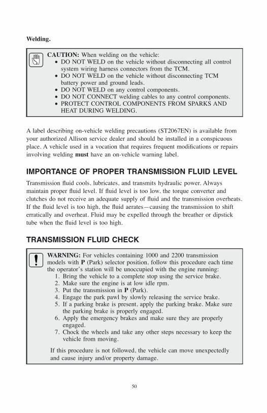
Welding.
CAUTION: When welding on the vehicle:• DO NOT WELD on the vehicle without disconnecting all control
system wiring harness connectors from the TCM.• DO NOT WELD on the vehicle without disconnecting TCM
battery power and ground leads.• DO NOT WELD on any control components.• DO NOT CONNECT welding cables to any control components.• PROTECT CONTROL COMPONENTS FROM SPARKS AND
HEAT DURING WELDING.
A label describing on-vehicle welding precautions (ST2067EN) is available fromyour authorized Allison service dealer and should be installed in a conspicuousplace. A vehicle used in a vocation that requires frequent modifications or repairsinvolving welding must have an on-vehicle warning label.
IMPORTANCE OF PROPER TRANSMISSION FLUID LEVELTransmission fluid cools, lubricates, and transmits hydraulic power. Alwaysmaintain proper fluid level. If fluid level is too low, the torque converter andclutches do not receive an adequate supply of fluid and the transmission overheats.If the fluid level is too high, the fluid aerates—causing the transmission to shifterratically and overheat. Fluid may be expelled through the breather or dipsticktube when the fluid level is too high.
TRANSMISSION FLUID CHECK
WARNING: For vehicles containing 1000 and 2200 transmissionmodels with P (Park) selector position, follow this procedure each timethe operator’s station will be unoccupied with the engine running:
1. Bring the vehicle to a complete stop using the service brake.2. Make sure the engine is at low idle rpm.3. Put the transmission in P (Park).4. Engage the park pawl by slowly releasing the service brake.5. If a parking brake is present, apply the parking brake. Make sure
the parking brake is properly engaged.6. Apply the emergency brakes and make sure they are properly
engaged.7. Chock the wheels and take any other steps necessary to keep the
vehicle from moving.
If this procedure is not followed, the vehicle can move unexpectedlyand cause injury and/or property damage.
50
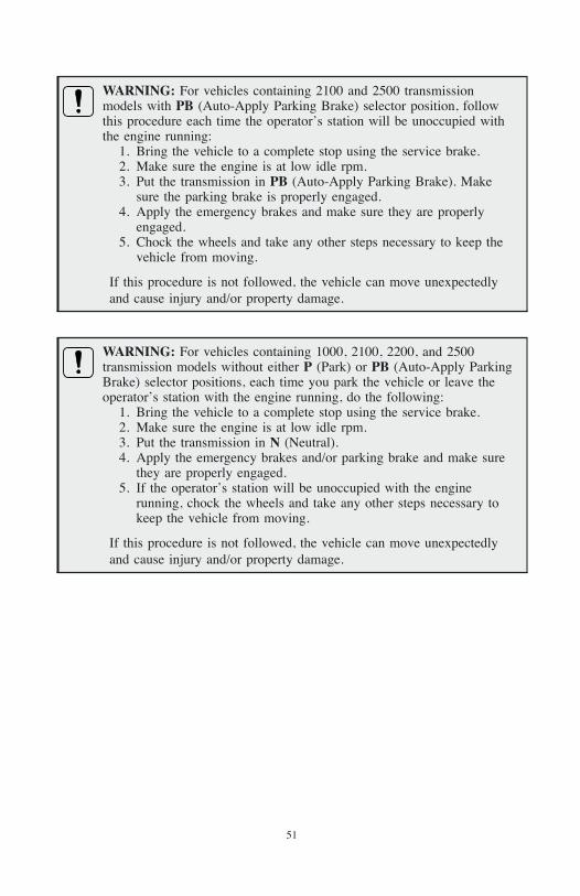
WARNING: For vehicles containing 2100 and 2500 transmissionmodels with PB (Auto-Apply Parking Brake) selector position, followthis procedure each time the operator’s station will be unoccupied withthe engine running:
1. Bring the vehicle to a complete stop using the service brake.2. Make sure the engine is at low idle rpm.3. Put the transmission in PB (Auto-Apply Parking Brake). Make
sure the parking brake is properly engaged.4. Apply the emergency brakes and make sure they are properly
engaged.5. Chock the wheels and take any other steps necessary to keep the
vehicle from moving.
If this procedure is not followed, the vehicle can move unexpectedlyand cause injury and/or property damage.
WARNING: For vehicles containing 1000, 2100, 2200, and 2500transmission models without either P (Park) or PB (Auto-Apply ParkingBrake) selector positions, each time you park the vehicle or leave theoperator’s station with the engine running, do the following:
1. Bring the vehicle to a complete stop using the service brake.2. Make sure the engine is at low idle rpm.3. Put the transmission in N (Neutral).4. Apply the emergency brakes and/or parking brake and make sure
they are properly engaged.5. If the operator’s station will be unoccupied with the engine
running, chock the wheels and take any other steps necessary tokeep the vehicle from moving.
If this procedure is not followed, the vehicle can move unexpectedlyand cause injury and/or property damage.
51
Fluid Check Procedure. Clean all dirt from around the end of the fluid fill tubebefore removing the dipstick. Do not allow dirt or foreign matter to enter thetransmission. Dirt or foreign matter in the hydraulic system may cause undue wearof transmission parts, make valves stick, and clog passages. Check the fluid levelusing the following procedure and report any abnormal fluid levels to your servicemanagement or an Allison distributor or dealer.
Cold Check Procedure. The purpose of the cold check is to determine if thetransmission has enough fluid to be operated safely until a hot check can be made.
CAUTION: The fluid level rises as fluid temperature rises. DO NOT fillthe transmission above the “COLD CHECK” band if the transmissionfluid is below normal operating temperatures. During operation, anoverfull transmission can become overheated, leading to transmissiondamage.
Check the fluid level as follows:
1. Bring the vehicle to a complete stop on a level surface using the servicebrake.
2. Make sure the engine is at low idle rpm (with fast idle disabled).
3. Put the transmission in P (Park), PB (Auto-Apply Parking Brake), orN (Neutral).
4. Apply any other parking brake, if present, and make sure it is properlyengaged.
5. Chock the wheels and take any other steps necessary to keep the vehiclefrom moving.
6. Run the engine at 1000–1500 rpm for at least one minute to purge air fromthe system. Apply the service brakes and shift to D (Drive), then toN (Neutral), and then shift to R (Reverse) to fill the hydraulic system.Finally, shift to P (Park) or PB (Auto-Apply Parking Brake), if available,or N (Neutral) and allow the engine to idle (500–800 rpm). Slowly releasethe service brakes.
7. With the engine running, remove the dipstick from the tube and wipe thedipstick clean.
8. Insert the dipstick into the tube and remove. Check the fluid level reading.Repeat the check procedure to verify the reading.
9. If the fluid level is within the “COLD CHECK” band (refer to Figure 4),the transmission may be operated until the fluid is hot enough to perform a“HOT RUN” check. If the fluid level is not within the “COLD CHECK”band, add or drain as necessary to bring it to the middle of the “COLDCHECK” band.
52
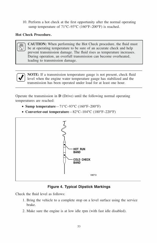
10. Perform a hot check at the first opportunity after the normal operatingsump temperature of 71°C–93°C (160°F–200°F) is reached.
Hot Check Procedure.
CAUTION: When performing the Hot Check procedure, the fluid mustbe at operating temperature to be sure of an accurate check and helpprevent transmission damage. The fluid rises as temperature increases.During operation, an overfull transmission can become overheated,leading to transmission damage.
NOTE: If a transmission temperature gauge is not present, check fluidlevel when the engine water temperature gauge has stabilized and thetransmission has been operated under load for at least one hour.
Operate the transmission in D (Drive) until the following normal operatingtemperatures are reached:
• Sump temperature—71°C–93°C (160°F–200°F)
• Converter-out temperature—82°C–104°C (180°F–220°F)
Check the fluid level as follows:
1. Bring the vehicle to a complete stop on a level surface using the servicebrake.
2. Make sure the engine is at low idle rpm (with fast idle disabled).
V06713
HOT RUNBAND
COLD CHECKBAND
Figure 4. Typical Dipstick Markings
53
3. Put the transmission in P (Park), PB (Auto-Apply Parking Brake), orN (Neutral).
4. Apply any other parking brake, if present, and make sure it is properlyengaged.
5. Chock the wheels and take any other steps necessary to keep the vehiclefrom moving.
6. With the engine running, remove the dipstick from the tube and wipe thedipstick clean.
7. Insert the dipstick into the tube and remove. Check the fluid level reading.Repeat the check procedure to verify the reading.
NOTE: Safe operating level is within the “HOT RUN” band on thedipstick (refer to Figure 4). The width of the “HOT RUN” bandrepresents approximately 1.0 liter (1.06 quart) of fluid at normaloperating sump temperature.
8. If the fluid level is not within the “HOT RUN” band, add or drain asnecessary to bring the fluid level to within the “HOT RUN” band.
Consistency of Readings. Always check the fluid level at least twice using theprocedure described above. Consistency (repeatable readings) is important tomaintaining proper fluid level. If inconsistent readings persist, check thetransmission breather to be sure it is clean and unclogged. If readings are stillinconsistent, contact your nearest Allison distributor or dealer.
KEEPING FLUID CLEANPrevent foreign material from entering the transmission by using clean containers,fillers, etc. Lay the dipstick in a clean place while filling the transmission.
CAUTION: Containers or fillers that have been used for antifreezesolution or engine coolant must NEVER be used for transmission fluid.Antifreeze and coolant solutions contain ethylene glycol which, if putinto the transmission, can cause the clutch plates and some seals to fail.
FLUID RECOMMENDATIONSHydraulic fluids (oils) used in the transmission are important influences ontransmission performance, reliability, and durability. Any fluids meetingDEXRON®-III specifications are acceptable for use in the 1000 and 2000 ProductFamily transmissions. TranSynd™ fluids fully meet the DEXRON®-IIIspecifications.
54
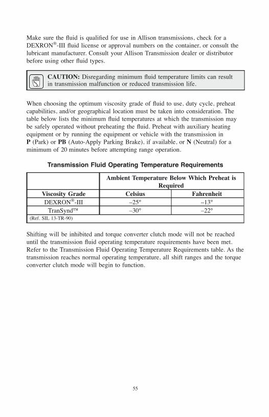
Make sure the fluid is qualified for use in Allison transmissions, check for aDEXRON®-III fluid license or approval numbers on the container, or consult thelubricant manufacturer. Consult your Allison Transmission dealer or distributorbefore using other fluid types.
CAUTION: Disregarding minimum fluid temperature limits can resultin transmission malfunction or reduced transmission life.
When choosing the optimum viscosity grade of fluid to use, duty cycle, preheatcapabilities, and/or geographical location must be taken into consideration. Thetable below lists the minimum fluid temperatures at which the transmission maybe safely operated without preheating the fluid. Preheat with auxiliary heatingequipment or by running the equipment or vehicle with the transmission inP (Park) or PB (Auto-Apply Parking Brake), if available, or N (Neutral) for aminimum of 20 minutes before attempting range operation.
Transmission Fluid Operating Temperature Requirements
Ambient Temperature Below Which Preheat isRequired
Viscosity Grade Celsius FahrenheitDEXRON®-III –25° –13°
TranSynd™ –30° –22°(Ref. SIL 13-TR-90)
Shifting will be inhibited and torque converter clutch mode will not be reacheduntil the transmission fluid operating temperature requirements have been met.Refer to the Transmission Fluid Operating Temperature Requirements table. As thetransmission reaches normal operating temperature, all shift ranges and the torqueconverter clutch mode will begin to function.
55
TRANSMISSION FLUID AND FILTER CHANGE INTERVALS
CAUTION: Transmission fluid and filter change frequency isdetermined by the severity of transmission service. To help avoidtransmission damage, more frequent changes can be necessary thanrecommended in the general guidelines when operating conditions createhigh levels of contamination or overheating.
Frequency. New vehicles delivered from the OEM with a mixture of TranSynd™and non-TranSynd™ fluid must follow fluid/filter change recommendationsoutlined in Schedule 1 of the Recommended Fluid and Filter Change Intervalsschedules. If the customer fills the transmission with TranSynd™ or TES 295equivalent, the change recommendations of Schedule 1 must be followed.
Upon the next oil change, if the customer reinstalls TranSynd™ or TES 295equivalent, the fluid/filter change recommendations outlined in Schedule 2 may beused. The recommendations in Schedule 2 are based upon Allison fluid changeprocedures and the transmission containing 100 percent of TranSynd™ fluid.
For transmissions that contain a mixture of TranSynd™ and non-TranSynd™fluids, refer to Schedule 1.
NOTE: Fluid Exchanging Machines are not recommended or recognizeddue to variation and inconsistencies that may not guarantee removal of100 percent of the used fluid.
Allison Transmission requires an initial filter change for the Spin-On ControlMain Filter during the first 8000 km (5000 miles) or 200 hours of service,whichever comes first. Following the initial filter change, change fluid/filters afterrecommended mileage, months, or hours have elapsed, whichever occurs first.Refer to the fluid change intervals listed in Schedule 1 or Schedule 2 forrecommendations. The transmission sump filter is permanent and does not requirereplacement except at overhaul.
Severe Vocations include On/Off-Highway, Refuse, City Transit, Shuttle, andMotorhomes. General Vocations include all other vocations. Local conditions,severity of operation or duty cycle may require more or less frequent fluid changeintervals that differ from the published recommended fluid change intervals ofAllison Transmission. Transmission protection and fluid change intervals can beoptimized by the use of fluid analysis.
The following tables are given only as a general guide for fluid and filter changeintervals.
56
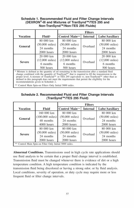
Schedule 1. Recommended Fluid and Filter Change Intervals(DEXRON®-III and Mixtures of TranSynd™/TES 295 and
Non-TranSynd™/Non-TES 295 Fluids)
Vocation Fluid*
FiltersControl Main** Internal Lube/Auxiliary
General
80 000 km(50,000 miles)
24 months2000 hours
80 000 km(50,000 miles)
24 months2000 hours
Overhaul
80 000 km(50,000 miles)
24 months2000 hours
Severe
20 000 km(12,000 miles)
6 months500 hours
20 000 km(12,000 miles)
6 months500 hours
Overhaul
20 000 km(12,000 miles)
6 months500 hours
* Mixture is defined as the quantity of oil remaining in the transmission after a standard fluidchange combined with the quantity of TranSynd™ that is required to fill the transmission to theproper level. A mixture of TranSynd™ or TES 295 equivalent vs. non-TranSynd™ other than asdefined in this paragraph does not meet the requirements that permit the eligibility for therecommendations given in Schedule 2.
** Control Main Spin-on Filters Only Initial 5000 miles.
Schedule 2. Recommended Fluid and Filter Change Intervals(TranSynd™/TES 295 Fluid)
Vocation FluidFilters
Control Main** Internal Lube/Auxiliary
General
160 000 km(100,000 miles)
48 months4000 hours
80 000 km(50,000 miles)
24 months2000 hours
Overhaul
80 000 km(50,000 miles)
24 months2000 hours
Severe
80 000 km(50,000 miles)
24 months2000 hours
80 000 km(50,000 miles)
24 months2000 hours
Overhaul
80 000 km(50,000 miles)
24 months2000 hours
** Control Main Spin-on Filter Only Initial 5000 miles.
Abnormal Conditions. Transmissions used in high cycle rate applications shoulduse fluid analysis to be certain that a proper fluid change interval is established.Transmission fluid must be changed whenever there is evidence of dirt or a hightemperature condition. A high temperature condition is indicated by thetransmission fluid being discolored or having a strong odor, or by fluid analysis.Local conditions, severity of operation, or duty cycle may require more or lessfrequent fluid or filter change intervals.
57
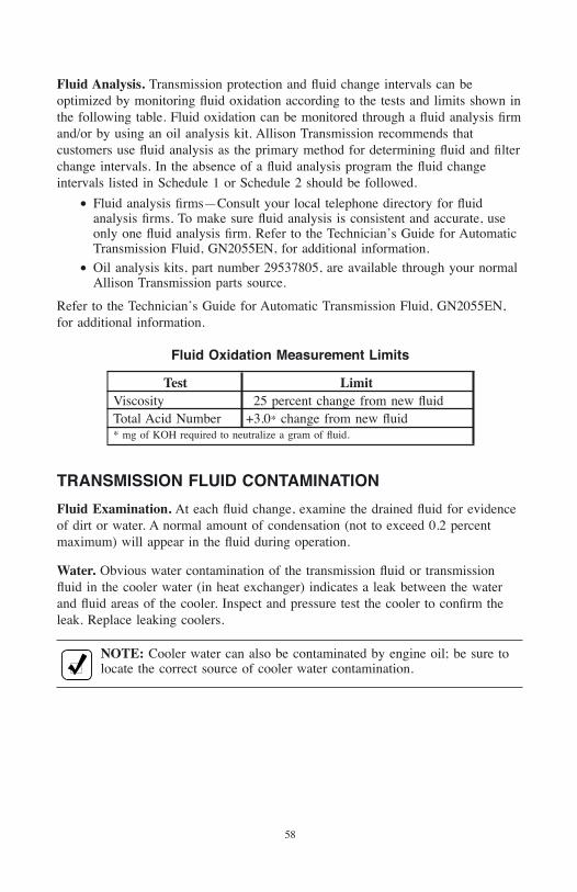
Fluid Analysis. Transmission protection and fluid change intervals can beoptimized by monitoring fluid oxidation according to the tests and limits shown inthe following table. Fluid oxidation can be monitored through a fluid analysis firmand/or by using an oil analysis kit. Allison Transmission recommends thatcustomers use fluid analysis as the primary method for determining fluid and filterchange intervals. In the absence of a fluid analysis program the fluid changeintervals listed in Schedule 1 or Schedule 2 should be followed.
• Fluid analysis firms—Consult your local telephone directory for fluidanalysis firms. To make sure fluid analysis is consistent and accurate, useonly one fluid analysis firm. Refer to the Technician’s Guide for AutomaticTransmission Fluid, GN2055EN, for additional information.
• Oil analysis kits, part number 29537805, are available through your normalAllison Transmission parts source.
Refer to the Technician’s Guide for Automatic Transmission Fluid, GN2055EN,for additional information.
Fluid Oxidation Measurement Limits
Test LimitViscosity 25 percent change from new fluidTotal Acid Number +3.0* change from new fluid* mg of KOH required to neutralize a gram of fluid.
TRANSMISSION FLUID CONTAMINATION
Fluid Examination. At each fluid change, examine the drained fluid for evidenceof dirt or water. A normal amount of condensation (not to exceed 0.2 percentmaximum) will appear in the fluid during operation.
Water. Obvious water contamination of the transmission fluid or transmissionfluid in the cooler water (in heat exchanger) indicates a leak between the waterand fluid areas of the cooler. Inspect and pressure test the cooler to confirm theleak. Replace leaking coolers.
NOTE: Cooler water can also be contaminated by engine oil; be sure tolocate the correct source of cooler water contamination.
58
Engine Coolant.
CAUTION: If the transmission fluid is contaminated by water, not toexceed 0.2 percent maximum by volume, or any trace of ethyleneglycol, disassemble the transmission and replace the following:
• Seals• Gaskets• Clutch/Friction plates• Bearings• Torque converters that cannot be disassembled• Components that have rusted• Solenoids that do not meet resistance specifications• Pressure switch manifold (PSM)• Internal Mode Switch (IMS)
Remove all traces of ethylene glycol and varnish deposits. Failure tofollow this procedure decreases transmission reliability and durability.
Metal. Metal particles in the fluid (except for the minute particles normallytrapped in the oil filter) indicate internal transmission damage. If these particlesare found in the sump, the transmission must be disassembled and closelyinspected to find their source. Metal contamination requires complete transmissiondisassembly. Clean all internal and external hydraulic circuits, cooler, and all otherareas where the particles could lodge.
TRANSMISSION FLUID AND FILTER CHANGEPROCEDURE
Drain Fluid.
1. Drain the fluid when the transmission is at normal operating sumptemperature of 71–93°C (160–200°F). Hot fluid flows quicker and drainsmore completely.
2. Remove the drain plug from the oil pan and allow the fluid to drain into asuitable container.
3. Examine the fluid as described in the TRANSMISSION FLUIDCONTAMINATION paragraph in this Section.
Replace Control-Main Filter.
1. Using a standard strap-type filter wrench or the J 45023 tool, remove thecontrol-main filter (refer to Figure 5) by rotating it in the counterclockwisedirection.
2. Remove the magnet from the filter attachment tube or from the top of thefilter element.
59
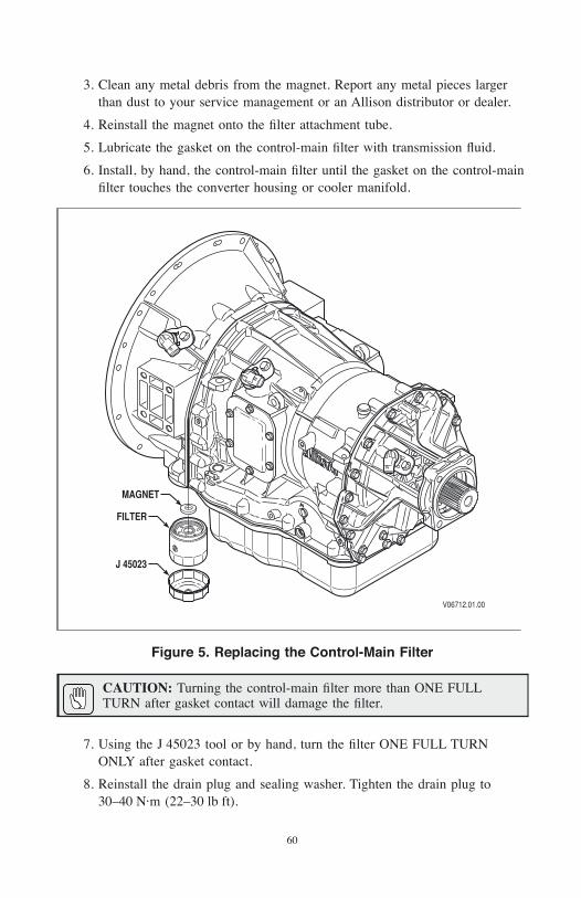
3. Clean any metal debris from the magnet. Report any metal pieces largerthan dust to your service management or an Allison distributor or dealer.
4. Reinstall the magnet onto the filter attachment tube.
5. Lubricate the gasket on the control-main filter with transmission fluid.
6. Install, by hand, the control-main filter until the gasket on the control-mainfilter touches the converter housing or cooler manifold.
CAUTION: Turning the control-main filter more than ONE FULLTURN after gasket contact will damage the filter.
7. Using the J 45023 tool or by hand, turn the filter ONE FULL TURNONLY after gasket contact.
8. Reinstall the drain plug and sealing washer. Tighten the drain plug to30–40 N·m (22–30 lb ft).
MAGNET
FILTER
J 45023
V06712.01.00
Figure 5. Replacing the Control-Main Filter
60
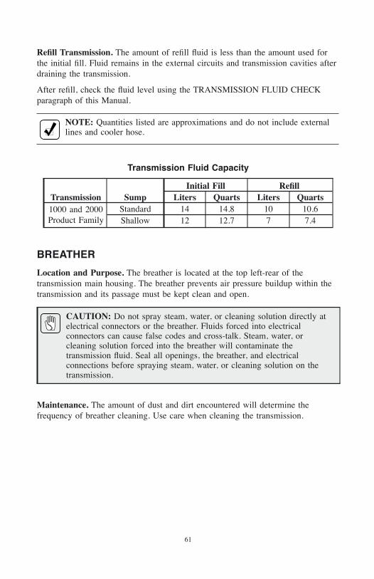
Refill Transmission. The amount of refill fluid is less than the amount used forthe initial fill. Fluid remains in the external circuits and transmission cavities afterdraining the transmission.
After refill, check the fluid level using the TRANSMISSION FLUID CHECKparagraph of this Manual.
NOTE: Quantities listed are approximations and do not include externallines and cooler hose.
Transmission Fluid Capacity
Transmission SumpInitial Fill Refill
Liters Quarts Liters Quarts1000 and 2000Product Family
Standard 14 14.8 10 10.6Shallow 12 12.7 7 7.4
BREATHER
Location and Purpose. The breather is located at the top left-rear of thetransmission main housing. The breather prevents air pressure buildup within thetransmission and its passage must be kept clean and open.
CAUTION: Do not spray steam, water, or cleaning solution directly atelectrical connectors or the breather. Fluids forced into electricalconnectors can cause false codes and cross-talk. Steam, water, orcleaning solution forced into the breather will contaminate thetransmission fluid. Seal all openings, the breather, and electricalconnections before spraying steam, water, or cleaning solution on thetransmission.
Maintenance. The amount of dust and dirt encountered will determine thefrequency of breather cleaning. Use care when cleaning the transmission.
61
DIAGNOSTIC CODES AND TOOLSThe illumination of the CHECK TRANS light or MIL (Malfunction IndicatorLight) any time after start-up indicates that the TCM has registered a DiagnosticTrouble Code (DTC). DTCs are used to identify the nature of a malfunction.
Use any Allison DOC™ diagnostic tool to access DTCs and troubleshoottransmission complaints.
The following Allison DOC™ diagnostic tools are available:
• Allison DOC™ For PC–Service Tool—full feature service tool.
• Allison DOC™ For Fleets–Service Tool—diagnostic only.
For more information regarding Allison DOC™ diagnostic tools, please visit
www.allisontransmission.com—Click on “Service” and then click on “DiagnosticTools”.
For additional help, contact an authorized Allison Transmission distributor orservice dealer or the Allison Technical Assistance Center at 800-252-5283.Refer to the Sales and Service Directory (SA2229EN) or use the AllisonTransmission Sales and Service Locator Tool on the Allison Transmission web siteat www.allisontransmission.com for current Allison Transmission authorizeddistributors and service dealers.
DIAGNOSTICS
62
OWNER ASSISTANCEThe satisfaction and goodwill of the owners of Allison transmissions are ofprimary concern to Allison Transmission, its distributors, and their dealers.
As an owner of an Allison transmission, you have service locations throughout theworld that are eager to meet your parts and service needs with:
• Expert service by trained personnel.
• Emergency service 24 hours a day in many areas.
• Complete parts support.
• Sales teams to help determine your transmission requirements.
• Product information and literature.
Normally, any situation that arises in connection with the sale, operation, orservice of your transmission will be handled by the distributor or dealer in yourarea. Check the telephone directory for the Allison Transmission service outletnearest you or utilize Allison Transmission’s Sales and Service Locator tool on theAllison Transmission web site at www.allisontransmission.com. You may alsorefer to Allison Transmission’s Worldwide Sales and Service Directory(SA2229EN).
We recognize, however, that despite the best intentions of everyone concerned,misunderstandings may occur. To further assure your complete satisfaction, wehave developed the following three-step procedure to be followed in the event aproblem has not been handled satisfactorily.
Step One—Discuss your problem with a member of management from thedistributorship or dealership. Frequently, complaints are the result of abreakdown in communication and can quickly be resolved by a member ofmanagement. If you have already discussed the problem with the Sales or ServiceManager, contact the General Manager. All Allison Transmission dealers areassociated with an Allison Transmission distributor. If the problem originates witha dealer, explain the matter to a management member of the distributorship withwhom the dealer has his service agreement. The dealer will provide his AllisonTransmission distributor’s name, address, and telephone number on request.
CUSTOMER SERVICE
63
Step Two—When it appears the problem cannot be readily resolved at thedistributor level without additional assistance, contact the Allison TechnicalAssistance Center at 800-252-5283. They will place you in contact with theRegional Customer Support Manager for your area.
For prompt assistance, please have the following information available:
• Name and location of authorized distributor or dealer.
• Type and make of vehicle/equipment.
• Transmission model number, serial number, and assembly number (ifequipped with electronic controls, also provide the TCM assembly number).
• Transmission delivery date and accumulated miles and/or hours ofoperation.
• Nature of problem.
• Chronological summary of your transmission’s history.
Step Three—If you are still not satisfied after contacting the Regional CustomerSupport Manager, present the entire matter to the Home Office by writing tothe following address:Allison TransmissionManager, Warranty AdministrationPO Box 894, Mail Code 462-470-PF9Indianapolis, IN 46206-0894
The inclusion of all pertinent information will assist the Home Office inexpediting the matter.
When contacting the Home Office, please keep in mind that ultimately theproblem will likely be resolved at the distributorship or dealership using theirfacilities, equipment, and personnel. Therefore, it is suggested that Step One befollowed when experiencing a problem.
Your purchase of an Allison Transmission product is greatly appreciated, and it isour sincere desire to assure complete satisfaction.
64
SERVICE LITERATUREAdditional service literature is available. This service literature provides fullyillustrated instructions for the operation, maintenance, service, overhaul, and partssupport of your transmission. To be sure you get maximum performance andservice life from your unit, you may order publications from:
SGI, Inc.Attn: Allison Literature Fulfillment Desk8350 Allison AvenueIndianapolis, IN 46268TOLL FREE: 888–666–5799INTERNATIONAL: 317–471–4995www.allisontransmission.com
Service Literature
Allison DOC™ For PC Users Guide GN3433ENAutomatic Transmission Fluid Technician’s Guide GN2055EN*In-Chassis Maintenance JA3664EN*In-Chassis Maintenance (Allison 4th Generation Controls) GN4008EN*Mechanic’s Tips MT3190EN*Mechanic’s Tips (Allison 4th Generation Controls) MT4007EN*Operator’s Manual OM4118EN*Parts Catalog PC3062ENParts Catalog CD-ROM CD3062ENPrinciples of Operation PO3065ENPrinciples of Operation (Allison 4th Generation Controls) PO4009ENService Manual SM3191ENService Manual (Allison 4th Generation Controls) SM4006ENTroubleshooting Manual TS3192ENTroubleshooting Manual (Allison 4th Generation Controls) TS3977EN*Worldwide Sales and Service Directory SA2229EN*Also available on the internet at www.allisontransmission.com
65
ALLISON TRANSMISSION REGIONAL OFFICES
EUROPE, MIDDLE EAST, AFRICA, AND INDIA
Allison Transmission Europe BVBaanhoek 1883361 GN Sliedrecht, The Netherlands31-78-6422-100
AUSTRIAAllison TransmissionAlmrauschwegA-4400 Steyr, Austria43-7252-46843
ENGLANDAllison TransmissionMillbrook Proving GroundsMidbrook, Bedford MK45 2JQUK44-1525-408600
FINLANDAllison TransmissionGeneral Motors Finland OYPajuniityntie 500320 Helsinki, Finland
FRANCEAllison TransmissionOpel France1 á 9 Avenue du MaraisB.P. 8495 101 Argenteuil Cedex, France33-1-3426-2153
GERMANYAllison TransmissionEisenstrasse 2D-65428 Rüsselsheim, Germany49-6142-602+322
SPAINAllison Transmission Spainc/o TransdieselE-28820 Coslada, MadridSpain34-91-6699-759
ITALYAllison Transmission Italyc/o Delphi Automotive SystemsVia Torino, 16610097 Collegno (TO)Italy39-011-4043.1
SWEDENAllison Transmission, NordenP.O. Box 100517 23 Bollebygd, Sweden46-33-2857-99
SOUTH AFRICAAllison Transmission DivisionEntrance 2, Second FloorSanlam Arena10 Cradock AvenueRosebank, JohannesburgSouth Africa27-11-788-4682
66
ASIA
JAPANAISIN GM Allison Co., Ltd.Shinagawa East One Tower 3F2-16-1, KonanMinato-ku, Tokyo108–0075 Japan81-3-6718-1660
KOREANo. 2110, 21 Fl. KEC Bldg.#275-7 Yangjea-dongSeocho-kuSeoul, 137-895, Korea82-2-3497-0401
BEIJINGAllison TransmissionBeijing Representative BranchGeneral Motors (China) InvestmentCompany, Ltd.Block C Guo Men Building, Rm. 3191 Zuo Jia ZhuangChao Yang DistrictBeijing 100028People’s Republic of China86-10-6468-785086-10-6468-7788
SHANGHAIAsia Pacific Office23rd Floor, Aurora PlazaNo. 99 Fucheng Road, PudongShanghai, 200120, China86-21-28996888
SOUTH EAST ASIA AND OCEANA
AUSTRALIAMTU Detroit Diesel Australia Pty Ltd.569 Grand Junction RoadGepps Cross, South AustraliaAustralia 509461-8-8300-8100
SINGAPOREAllison Transmission15 Benoi SectorJurong Town, Singapore 62984965-6267-1600
SOUTH AMERICA
BRAZILAllison TransmissionRua Agostinho Togneri57 - Jardim Jurubatuba - Santo AmaroSao Paulo (SP), Brazil CEP 04690-09055-11-5633-2599
ARGENTINA, CHILE, PARAGUAY,URUGUAY, VENEZUELAAv. Leandro Alem, 855Piso 2Buenos Aires, Capital Federal CP C1001AAPArgentina54-11-4510-2758
67

OM4118EN 200509 Printed in USA 200509www.allisontransmission.com
C
M
Y
CM
MY
CY
CMY
K
OM4118EN B.pdf 9/30/05 8:38:22 AMOM4118EN B.pdf 9/30/05 8:38:22 AM