Embed Size (px)
Citation preview
Programming with the Intel Galileo
Joystick Control
Welcome to another lesson of programming with the Intel Galileo. In this lesson we will be using
a joystick to control LED’s on an LED matrix.
The joystick has two voltage inputs, one for Up/Down tilting, and the other for Left/Right
tilting. A variable resistor is connected to each of the two voltage inputs. The amount of
resistance provided by the variable resistors is dependent upon how far the joystick is
tilted from center.
For example, when the joystick is tilted to the right, the resistance on the variable resistor,
connected to the L/R voltage supply, is decreased, resulting in a greater voltage value
being output on the L/R pin. When the joystick is tilted to the left, the resistance on the
variable resistor is increased, resulting in a lower voltage value being output on the L/R
pin.
Follow the diagram below to correctly connect the joystick to the micro-controller.
Note: Your capacitors may have a polarity that must match up.
Important: Make sure to include the resistors and capacitors when connecting the
joystick to the Galileo. Without them, there is a risk of burning out the microcontroller.
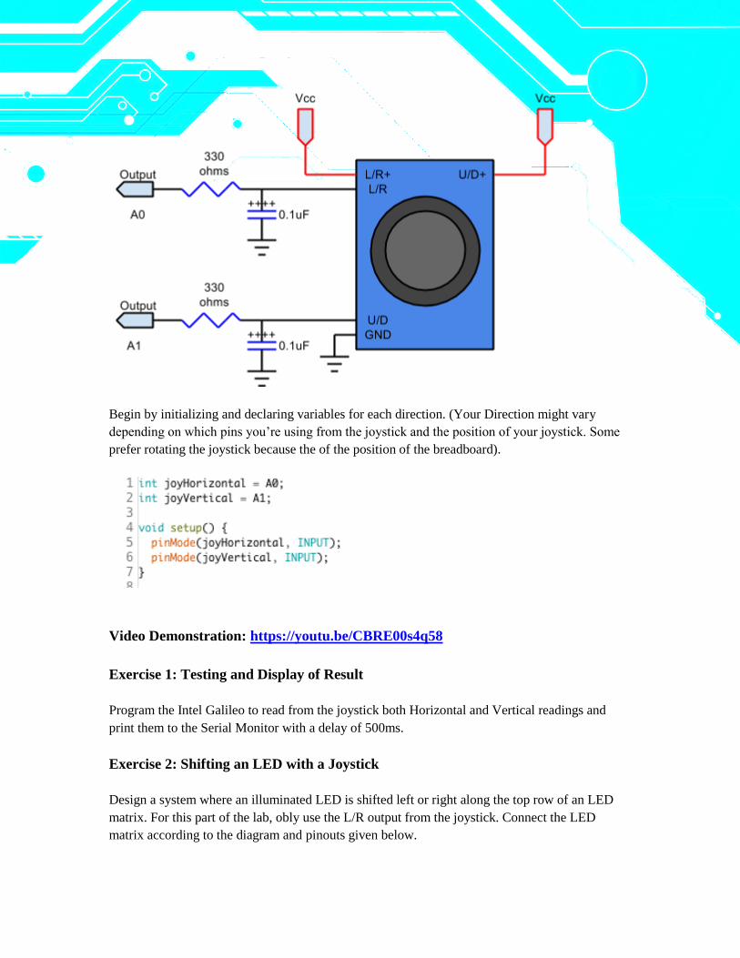
Begin by initializing and declaring variables for each direction. (Your Direction might vary
depending on which pins you’re using from the joystick and the position of your joystick. Some
prefer rotating the joystick because the of the position of the breadboard).
Video Demonstration: https://youtu.be/CBRE00s4q58
Exercise 1: Testing and Display of Result
Program the Intel Galileo to read from the joystick both Horizontal and Vertical readings and
print them to the Serial Monitor with a delay of 500ms.
Exercise 2: Shifting an LED with a Joystick
Design a system where an illuminated LED is shifted left or right along the top row of an LED
matrix. For this part of the lab, obly use the L/R output from the joystick. Connect the LED
matrix according to the diagram and pinouts given below.
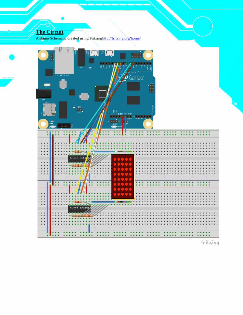
The Circuit Arduino Schematic created using Fritzinghttp://fritzing.org/home/
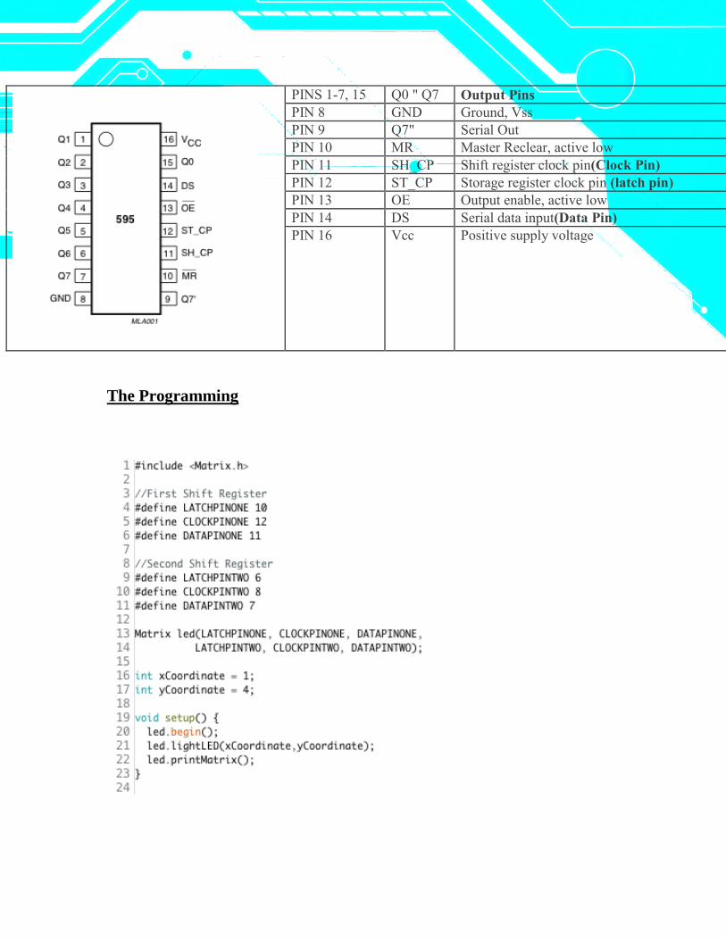
PINS 1-7, 15 Q0 " Q7 Output Pins
PIN 8 GND Ground, Vss
PIN 9 Q7" Serial Out
PIN 10 MR Master Reclear, active low
PIN 11 SH_CP Shift register clock pin(Clock Pin)
PIN 12 ST_CP Storage register clock pin (latch pin)
PIN 13 OE Output enable, active low
PIN 14 DS Serial data input(Data Pin)
PIN 16 Vcc Positive supply voltage
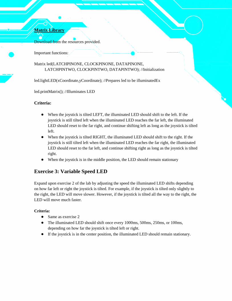
The Programming
Matrix Library
Download from the resources provided.
Important functions:
Matrix led(LATCHPINONE, CLOCKPINONE, DATAPINONE,
LATCHPINTWO, CLOCKPINTWO, DATAPINTWO); //Initialization
led.lightLED(xCoordinate,yCoordinate); //Prepares led to be illuminatedEx
led.printMatrix(); //Illuminates LED
Criteria:
● When the joystick is tilted LEFT, the illuminated LED should shift to the left. If the
joystick is still tilted left when the illuminated LED reaches the far left, the illuminated
LED should reset to the far right, and continue shifting left as long as the joystick is tilted
left.
● When the joystick is tilted RIGHT, the illuminated LED should shift to the right. If the
joystick is still tilted left when the illuminated LED reaches the far right, the illuminated
LED should reset to the far left, and continue shifting right as long as the joystick is tilted
right.
● When the joystick is in the middle position, the LED should remain stationary
Exercise 3: Variable Speed LED
Expand upon exercise 2 of the lab by adjusting the speed the illuminated LED shifts depending
on how far left or right the joystick is tilted. For example, if the joystick is tilted only slightly to
the right, the LED will move slower. However, if the joystick is tilted all the way to the right, the
LED will move much faster.
Criteria:
● Same as exercise 2
● The illuminated LED should shift once every 1000ms, 500ms, 250ms, or 100ms,
depending on how far the joystick is tilted left or right.
● If the joystick is in the center position, the illuminated LED should remain stationary.
Exercise 4: Shifting an LED in 8 Directions
Design a system that moves an illuminated LED (controlled by the joystick) around a 5x8 LED
matrix. The LED can be moved up, down, left, right, up/left, up/right, down/left, or down/right.
Criteria:
● If the illuminated LED reaches an edge of a matrix, it remains there unless moved away
from the edge. For example, if the illuminated LED reaches the far left edge of the
matrix, continuing to tilt the joystick left will have no effect, but tilting the joystick right
will move the illuminated LED away from the edge.
Exercise 5 (challenge): Variable Speed LED in 8 Directions
Expand upon exercise 4 by increasing the speed at which the illuminated LED shifts depending
upon how far the joystick is tilted from center.
Criteria:
● Same as part 4 only with the added criteria of variable shifting speed.
● Possible shifting speeds are: 1000 ms, 500 ms, 250 ms, and 100 ms.
● The farther the joystick is tilted away from center, the faster the LED is shifted.