Embed Size (px)
Citation preview
Copyright © 2014 Rockwell Automation, Inc. All Rights Reserved.Rev 5058-CO900F
PUBLIC INFORMATION
T99 - ISO 14119:2013Interlocking Devices Associated With Guards: A Small Standard With a Lot of Requirements

Copyright © 2014 Rockwell Automation, Inc. All Rights Reserved.PUBLIC INFORMATION 2
Agenda
Who does this affect and how?
ISO 14119:2013 – Major Shifts
Scope, What, Where, When and Why…
Key Impacts

Copyright © 2014 Rockwell Automation, Inc. All Rights Reserved.PUBLIC INFORMATION
Scope: What is ISO 14119:2013?
ISO 14119:2013 is a B2 standard
Guard Interlocking
Design – interlocking device manufactures
Selection – machine builders and integrators
Replaces ISO 14119:1998 as a harmonized standard (BS EN ISO)
Supersedes EN 1088:1995
C: Detailed Safety Requirements for Particular MachinesB2: Standards on SafeguardsB1: Particular Safety Aspects
A: Basic Concepts & Principles - Applies to all Machinery
3

Copyright © 2014 Rockwell Automation, Inc. All Rights Reserved.PUBLIC INFORMATION
Where Does ISO 14119:2013 apply?
4
Europe as EN ISO 14119
Any country that uses ISO standards
ISO 14119 is THE global safety interlock device standard
Anyone who follows ANSI standards
ANSI/ISO 12100 - references ISO 14119 (x10)
No equivalent standard in the USA or Canada.
ANSI B11.19, CSA Z432, ANSI RIA R15.06 and CSA Z434
Discuss safeguarding and interlocking
No standards for certifying interlocking devices used for safeguarding.

Copyright © 2014 Rockwell Automation, Inc. All Rights Reserved.PUBLIC INFORMATION
When Does ISO 14119:2013 apply?
April 2015 - conflicting standards must be withdrawn
18 months from October 2013 allows time to meet the standard
Testing
Design
Documentation
5
Copyright © 2014 Rockwell Automation, Inc. All Rights Reserved.PUBLIC INFORMATION
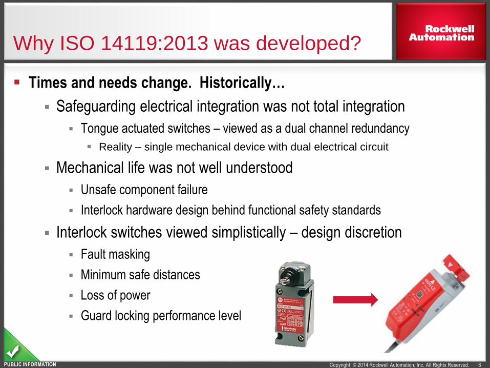
Why ISO 14119:2013 was developed?
6
Times and needs change. Historically…
Safeguarding electrical integration was not total integration
Tongue actuated switches – viewed as a dual channel redundancy
Reality – single mechanical device with dual electrical circuit
Mechanical life was not well understood
Unsafe component failure
Interlock hardware design behind functional safety standards
Interlock switches viewed simplistically – design discretion
Fault masking
Minimum safe distances
Loss of power
Guard locking performance level

Copyright © 2014 Rockwell Automation, Inc. All Rights Reserved.PUBLIC INFORMATION
Major Shifts: ISO 14119:2013
References ISO standards
Four types of interlocking devices defined and described
Minimizing interlock defeat is a requirement
Interlock technology affects functional safety
Guard locking has added descriptions and requirements Power to lock vs. power to unlock
Supplementary release
Mechanical requirements
Multiple safety functions
Product certification requirements
Mechanical and integration requirements
7
Expect that the next revision will clean-up some things and address functional safety issues

Copyright © 2014 Rockwell Automation, Inc. All Rights Reserved.PUBLIC INFORMATION
ISO 14119 references many standards
8
Normative References: ”Indispensable for its application”
ISO 12100 Risk assessment and risk reduction
ISO 13849-1&2 Safety-related parts of control systems
IEC 60204-1 Electrical equipment of machines
IEC 60947-5-3 Control circuit devices and switching elements
IEC 62061 Functional Safety
Other standards referenced in ISO 14119
ISO 11161 Integrated Manufacturing Systems
ISO 13855 Safeguard safe distance and approach speeds
ISO 13857 Safe distance to prevent reaching hazards by limbs
ISO 14120 Guards, fixed and moveable
ISO TR 24119 Fault masking of series guard interlocking

Copyright © 2014 Rockwell Automation, Inc. All Rights Reserved.PUBLIC INFORMATION 9
Interlocking Device TypesDefined by actuation principle and actuator type
Actuation Principle Actuator Coding & ExamplesType Interlockper ISO 14119
Example Rockwell
Automation®
Product Line*
MechanicalPhysical
contact
force
uncoded
Rotary cam
Type 1
Safety Limit Switch
Linear cam Safety Limit Switch
HingeRotocam™ &
Safety Limit Switch
coded
Tongue low coding
(shaped actuator) Type 2Trojan™ / TLS GD2
ProSafe®Trapped-key med or high
Non-
contact
Inductive
uncoded
Suitable ferric metal
Type 3(see 7.1a)
– – –
Magnetic Magnet, solenoid Ferrogard™
Capacitive Any suitable object – – –
Ultrasonic Any suitable object – – –
Optic Any suitable object – – –
Magnetic
coded
Coded magnet
Type 4
Sipha™ & MC1/MC2
SensaGuard™,
TLSZ & LZRFID Coded RFID tag
– – –Optic Optically coded tag
Reference: ISO 14119 – Table 1
* Pending Approval
Types are NOT
in hierarchal order

Copyright © 2014 Rockwell Automation, Inc. All Rights Reserved.PUBLIC INFORMATION
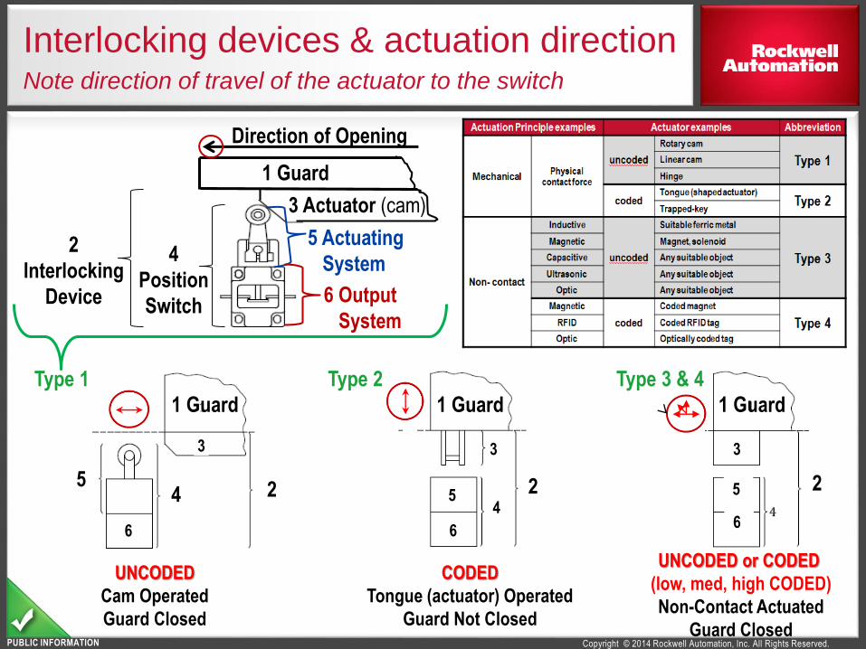
Interlocking devices & actuation directionNote direction of travel of the actuator to the switch
Type 1Type 3 & 4
3 Actuator (cam)
Direction of Opening
1 Guard
5 Actuating
System
6 Output
System
4
Position
Switch
2
Interlocking
Device
1 Guard1 Guard
1 Guard
2 22
55 5
6 6 6
44
Type 2
Type 2: CODED
Tongue (actuator) Operated
Guard Not Closed
Type 1: UNCODED
Cam Operated
Guard Closed
Type 3: UNCODED or Type 4: CODED
(Type 4 can be low, med, high CODED)
Non-Contact Actuated – Guard Closed
333
Actuation Actuator Coding & Example Type
Mec
han
ical
Physical
contact
force
uncodedRotary cam
Type 1Linear cam
Hinge
codedTongue
Type 2Trapped-key
No
n-
con
tact
Inductive
uncoded
Suitable ferric metal
Type 3Magnetic Magnet, solenoid
CapacitiveAny suitable objectUltrasonic
Optic
Magnetic
codedCoded magnet
Type 4RFID Coded RFID tag
Optic Optically coded tag

Copyright © 2014 Rockwell Automation, Inc. All Rights Reserved.PUBLIC INFORMATION
ISO 14119 Coded actuator definition
11
Coded actuator (3.13)
actuator which is specially designed (e.g. by shape) to actuate a certain position switch <manufacturer must specify the coding>
low level coded actuator (3.13.1)coded actuator for which 1 to 9 variations in code are available
Example: most coded magnetic actuators and standard coded safety RFID actuators
medium level coded actuator (3.13.2)coded actuator for which 10 to 1,000 variations in code are available
high level <unique> coded actuator (3.13.3)coded actuator for which more than 1,000 variations are available
Example: Unique coding for most RFID safety switches
with high coded safety switches, there are fewer installation requirements & defeat analysis
Actuation Actuator Coding & Example ISO 14119
Mec
han
ical
Physical
contact
force
Un-coded
Rotary cam
Type 1Linear cam
Hinge
CodedTongue low coding
Type 2Trapped-key med or high coding
No
n-
con
tact
Inductive
Un-coded
Suitable ferric metal
Type 3
Magnetic Magnet, solenoid
Capacitive
ANY suitable objectUltrasonic
Optic
Magnetic
Coded
Coded magnet
Type 4RFID Coded RFID tag
Optic Optically coded tag

Copyright © 2014 Rockwell Automation, Inc. All Rights Reserved.PUBLIC INFORMATION
ISO 14119 “Defeat” definitions
12
Defeat (3.7): action that makes interlocking devices inoperative or bypasses
them with the result that a machine is used in a manner not intended by the
designer or without the necessary safety measures.
Defeat in a reasonably foreseeable manner (3.8): defeat of an interlocking
device either manually or by using readily available objects (see Note 2)
Note 1: This definition includes the removal of switches or actuators using tools that are
needed for the intended use of the machine or that are readily available (screwdrivers,
wrenches, hexagon keys, pliers).
Note 2: Readily available objects for substitute actuation include screws, needles and
sheet-metal pieces, objects in daily use such as keys, coins, adhesive tape, string and
wire, spare keys for the trapped-key interlocking devices, and spare actuators (hence
emphasis on UNIQUE/ HIGH coding).
Emphasis on HIGH coding

Copyright © 2014 Rockwell Automation, Inc. All Rights Reserved.PUBLIC INFORMATION
7. Design to minimize defeat possibilities
Implement interlock & guard locking devices to minimize
motivation to defeat (hide limit switches & cams, hide low
coded actuators, OR use HIGH coded actuators …)
Modify the machine(add modes with risk reduction features) to minimize the motivation to defeat
Annex H is a lot of work for the integrator
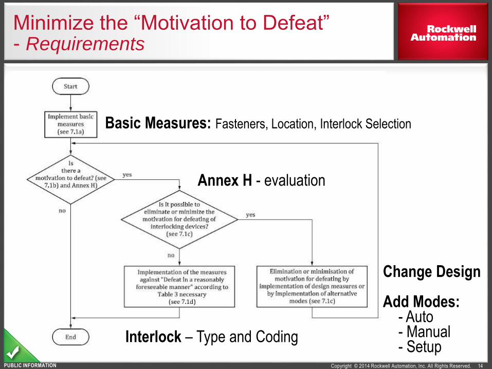
Figure 9 – Methodology for determining the possible incentive and the required measures by the manufacturer <integrator>
Copyright © 2014 Rockwell Automation, Inc. All Rights Reserved.PUBLIC INFORMATION
Basic Measures: Fasteners, Location, Interlock Selection
Change Design
Add Modes:- Auto- Manual- Setup
Minimize the “Motivation to Defeat”- Requirements
Annex H - evaluation
Interlock – Type and Coding
14

Copyright © 2014 Rockwell Automation, Inc. All Rights Reserved.PUBLIC INFORMATION
Minimizing Defeat: Achieved by Selection, Installation, Integration
15
ISO 14119, Clause 7.1 a): Design to minimize defeat possibilities of interlocking devices
a) Implement the basic measures described in 5.2 Arrangement and fastening of switches, 5.3 Arrangement
and fastening of actuators, 5.4 Actuation modes of interlocking devices, 5.7.3.3 Basic measures for minimizing
defeat possibilities and 6.2.2 Specific requirements for selection of guard locking devices.
Type 3 interlocking devices shall not be used unless it is shown by risk assessment that in the application the
device cannot be defeated in a reasonably foreseeable manner.
b) Check whether the motivation to defeat the interlocking devices in reasonably foreseeable manner exists.
c) Check whether the motivation can be minimized or minimized by:
— design measures and/or
— alternative modes.
Implement those measures if possible.
NOTE 3: The implementation of alternative modes of operation can avoid the motivation to defeat. Alternative
modes of operation can be, for example, special modes for setting, tool changing, fault finding, maintenance or
process observation. They depend highly on the type of machine and its application and cannot be dealt with
comprehensively in this standard.
d) If foreseeable motivation for defeat continues to exist, additional measures are required (see 7.2).
Type 3 (non-contact UNCODED) shall NOT be used unless risk assessment shows the device cannot be
defeated in a reasonably foreseeable manner.

Copyright © 2014 Rockwell Automation, Inc. All Rights Reserved.PUBLIC INFORMATION
Minimizing Defeat by Install / IntegrationType 1 Hinged – Requirements
16
Mandatory
Non-detachablefixing of switch & actuator
ISO 14119, 7.2.c & Table 3
OR if detachable fixing used, then it might be mandatory to do one of the following:
1) Mount out of reach ISO 14119, 7.2.a) 1) & Table 3OR
2) Additional interlocking device and plausibility checking ISO 14119, 7.2.d) 2) & Table 3
Recommended
Additional interlocking device
and plausibility checking ISO 14119, 7.2.d) 2) & Table 3
Non-detachable fixing (for example, welding, gluing, one-way screws, riveting)
Actuator examples ISO 14119 Product *
Mechanical
uncodedHinge Type 1 Rotocam™
* Pending Approval

Copyright © 2014 Rockwell Automation, Inc. All Rights Reserved.PUBLIC INFORMATION
Define Design RequirementsAvoid the defeat of interlock devices
17
Type 1 - Hinged
Mandatory: Non-detachable
fixing of switch and actuator
Type 1 (Not Hinged) and Type 3
Mandatory to do 1 of the following:
1) Mount out of Reach
2) Physically Obstruct / Shield
3) Hide the switch
4) Status Monitoring or Cyclic Testing
5) Non-detachable switch and actuator
Recommended: Additional interlocking device and plausibility checking
Non-detachable fixing (e.g. welding, gluing, one-way screws, riveting)
Actuation Principle Actuator ExampleISO
14119
Example
Product *
Mechanical
UNCODED
Physical
contact
force
Rotary cam
Type
1
Safety Limit
SwitchLinear cam
Hinge Rotocam™
Non-
contact
UNCODED
InductiveSuitable ferric
metal
Type
3
– – –
Magnetic Magnet, solenoid Ferrogard™
CapacitiveAny suitable
object
– – –
Ultrasonic – – –
Optic – – –

Copyright © 2014 Rockwell Automation, Inc. All Rights Reserved.PUBLIC INFORMATION
Minimizing Defeat by Install / Integration
18
Type 1 HINGED:
Mandatory: non-detachablefixing of switch and actuator
ISO 14119, 7.2.c & Table 3
Type 1 NOT Hinge, Type 2 & Type 3
Mandatory: choose at least 1 (risk assessment determines if more than 1 of the following is needed):
1) Mount out of reach ISO 14119, 7.2.a) 1) & Table 3
2) Physical obstruction / shielding ISO 14119, 7.2.a) 2) & Table 3
3) Mounting in a hidden position ISO 14119, 7.2.a) 3) & Table 3
4) Status monitoring or cyclic testing ISO 14119, 7.2.d) 1) i) and ii) & Table 3
For Type 1 (not hinge) and Type 3, this is also a choice in addition to 1 through 4
5) Non-detachable switch and actuator ISO 14119, 7.2.c) & Table 3
Recommended: Additional interlocking device and plausibility checking ISO 14119, 7.2.d) 2) & Table 3
Non-detachable fixing (For example, welding, gluing, one-way screws, riveting)
Actuator examples Interlock Product Line*
Mechanical
uncoded
Rotary or Linear cam
Type 1Safety Limit Switch
HingeRotocam™ &
Safety Limit Switch
Mechanical
codedTongue low coding
(shaped actuator)Type 2
Trojan™ / TLS GD2
Prosafe™
Non-
Contact
uncoded
Suitable ferric metal
Type 3
– – –
Ferrogard™Magnet, solenoid
Any suitable object – – –
* Pending Approval

Copyright © 2014 Rockwell Automation, Inc. All Rights Reserved.PUBLIC INFORMATION
Minimizing Defeat by Install / IntegrationType 1 (not Hinged) Type 2, Type 3 & low/med coded Type 4
19
Mandatory: choose at least 1 (risk assessment determines
if more than 1 is needed):
1) Mount out of reach ISO 14119, 7.2.a) 1) & Table 3
2) Physical obstruction / shielding ISO 14119, 7.2.a) 2) & Table 3
3) Mounting in a hidden position ISO 14119, 7.2.a) 3) & Table 3
4) Status monitoring or cyclic testing ISO 14119, 7.2.d) 1) i) and ii) & Table 3
5) Non-detachable fixing of
* switch and actuator (Type 1 & Type 2) ISO 14119, 7.2.c) & Table 3
* actuator only (Type 3 & low/med Type 4) ISO 14119, 7.2.c) & Table 3
Recommended: Additional interlocking device
and plausibility checking ISO 14119, 7.2.d) 2) & Table 3
Non-detachable fixing (For example, welding, gluing, one-way screws, riveting)
Actuator examplesMechanical
uncodedRotary or Linear
Mechanical
codedTongue low coding
(shaped actuator)
Non-
Contact
uncoded
Suitable ferric metal
Magnet, solenoid
Any suitable object
* Pending Approval

Copyright © 2014 Rockwell Automation, Inc. All Rights Reserved.PUBLIC INFORMATION
Minimizing Defeat by Install / IntegrationType 1 (not Hinged) – Requirements
20
Type 1 NOT Hinge, Type 2 & Type 3 (not high)
Mandatory: choose at least 1 (risk assessment determines if more than 1 is needed):
1) Mount out of reach ISO 14119, 7.2.a) 1) & Table 3
2) Physical obstruction / shielding ISO 14119, 7.2.a) 2) & Table 3
3) Mounting in a hidden position ISO 14119, 7.2.a) 3) & Table 3
4) Status monitoring or cyclic testing ISO 14119, 7.2.d) 1) i) and ii) & Table 3
For Type 1 (not hinge) and Type 3, this is also a choice in addition to 1 through 4
5) Non-detachable switch and actuator ISO 14119, 7.2.c) & Table 3
Recommended: Additional interlocking device and plausibility checking ISO 14119, 7.2.d) 2) & Table 3
Non-detachable fixing (For example, welding, gluing, one-way screws, riveting)
Actuator examples Interlock Product Line*Mechanical
uncodedRotary or Linear cam Type 1 Safety Limit Switch
Mechanical
codedTongue low coding
(shaped actuator)Type 2
Trojan™ / TLS GD2
Prosafe™
Non-
Contact
uncoded
Suitable ferric metal
Type 3
– – –
Ferrogard™Magnet, solenoid
Any suitable object – – –
* Pending Approval

Copyright © 2014 Rockwell Automation, Inc. All Rights Reserved.PUBLIC INFORMATION
Define Design RequirementsAvoid the defeat of interlock devices
21
Type 2 and Type 4
ALL coding Mandatory:
Non-detachable actuator
Low or Medium Coding
Mandatory: at least 1 of the following:
1) Mount out of Reach
2) Physically Obstruct / Shield
3) Hide
4) Status Monitoring or Cyclic Testing
Recommended: Additional interlocking device and plausibility checking
Non-detachable fixing, e.g. welding, gluing, one-way screws, riveting
Measures Against Defeat: Simplified with high coded safety switches
Actuation PrincipleActuator
Example
ISO
14119
Example
Product*
Mechanical
CODED
Physical
contact
force
Tongue
low coding Type
2
Trojan™
TLS GD2
ProSafe®Trapped-key
med or high
Non-
contact
CODED
MagneticCoded
magnet
Type
4
Sipha™ &
MC1/MC2
SensaGuard™
TLSZ & LZRFIDCoded RFID
tag
– – –OpticOptically
coded tag

Copyright © 2014 Rockwell Automation, Inc. All Rights Reserved.PUBLIC INFORMATION
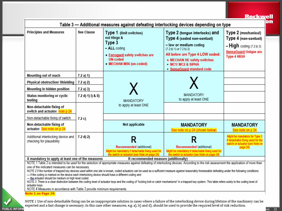
Measures Against Defeat: documentation
required unless using high coded safety switches
There are new requirements of the design process, design decisions, and proof of due diligence.
Part of Clause 7.2: Additional measures to minimize defeat possibilities
Copyright © 2014 Rockwell Automation, Inc. All Rights Reserved.PUBLIC INFORMATION 23

Copyright © 2014 Rockwell Automation, Inc. All Rights Reserved.PUBLIC INFORMATION
Annex HEvaluation of Motivation to Defeat
24

Copyright © 2014 Rockwell Automation, Inc. All Rights Reserved.PUBLIC INFORMATION
Minimizing Defeat by Coding Selection
25
Coded Actuator (3.13)
actuator which is specially designed to actuate a certain position switch
low level coded actuator (3.13.1)
coded actuator for which 1 to 9 variations in code are available
Ex: tongue interlocks, coded magnetic, and standard-code RFID
medium level coded actuator (3.13.2)
coded actuator for which 10 to 1,000 variations in code are available
high level <unique> coded actuator (3.13.3)
coded actuator for which more than 1,000 variations are available
Ex: Unique coded RFID
High coded safety switches have fewer installation and defeat analysis requirements

Copyright © 2014 Rockwell Automation, Inc. All Rights Reserved.PUBLIC INFORMATION
Series Connection
26
Restrictions for series connected contacts (electromechanical)
8.6 Logical series connection of interlocking devices
When interlocking devices with redundant contacts are connected in series the detection of a single fault can be
masked by the actuation of any interlocking device connected between the fault and the safety related control system.
Maximum of 5 dry contact switches in series for PLd - for 1 frequently used guard
Detailed in: ISO/TR 24119
>1/hr <1/hr <1/hr <1/hr <1/hr

Copyright © 2014 Rockwell Automation, Inc. All Rights Reserved.PUBLIC INFORMATION
Motivation to Defeat
27
Defeat
Action that makes interlocking devices inoperative or bypasses them with the result that a
machine is used in a manner not intended by the designer or without the necessary safety
measures
Defeat in a reasonably foreseeable manner
Defeat of an interlocking device either manually or by using readily available objects
Note 1: This definition includes the removal of switches or actuators using tools that are needed for
the intended use of the machine or that are readily available (screw drivers, wrenches, hexagon
keys, pliers)
Note 2: Readily available objects for substitute actuation include screws, needles and sheet-metal
pieces, objects in daily use such as keys, coins, adhesive tape, string and wire, spare keys for the
trapped-key interlocking devices, and spare actuators
Emphasis on HIGH coding

Copyright © 2014 Rockwell Automation, Inc. All Rights Reserved.PUBLIC INFORMATION
Interlocking – guard location and guard openings
28
While the guards are closed and equipment can operate, the guard openings and its distance to the hazards
is required to meet ISO 13857.
Example Body PartGraphic
(upper limbs shown, but table is
applicable to both upper & lower)
Opening (e)
(Smallest Dimension) in mm
Minimum (Safe) Distance Sr
Slotted Square Round
Finger tip
0 < e ≤ 4 ≥ 2 ≥ 2 ≥ 2
4 < e ≤ 6 ≥ 10 ≥ 5 ≥ 5
6 < e ≤ 8 ≥ 20 ≥ 15 ≥ 5
Finger to knuckle joint
6 < e ≤ 8 ≥ 20 ≥ 15 ≥ 5
8 < e ≤ 10 ≥ 80 ≥ 25 ≥ 20
Hand
10 < e ≤ 12 ≥ 100 ≥ 80 ≥ 80
12 < e ≤ 20 ≥ 120 ≥ 120 ≥ 120
20 < e ≤ 30 ≥ 850 ≥ 120 ≥ 120
Arm up to junction with
shoulder
30 < e ≤ 40 ≥ 850 ≥ 200 ≥ 120
40 < e ≤ 120 ≥ 850 ≥ 850 ≥ 850
Over
(reach over the guard)UPPER Limb ONLY 120 < e See Reaching Over
Under
(reach under the guard)Upper or Lower Limbs 180 < e See Reaching Under
Source: ISO 13857:2008, 4.2.4.1, Table 4, with addition of “Over” and “Under” rows]
Copyright © 2014 Rockwell Automation, Inc. All Rights Reserved.PUBLIC INFORMATION
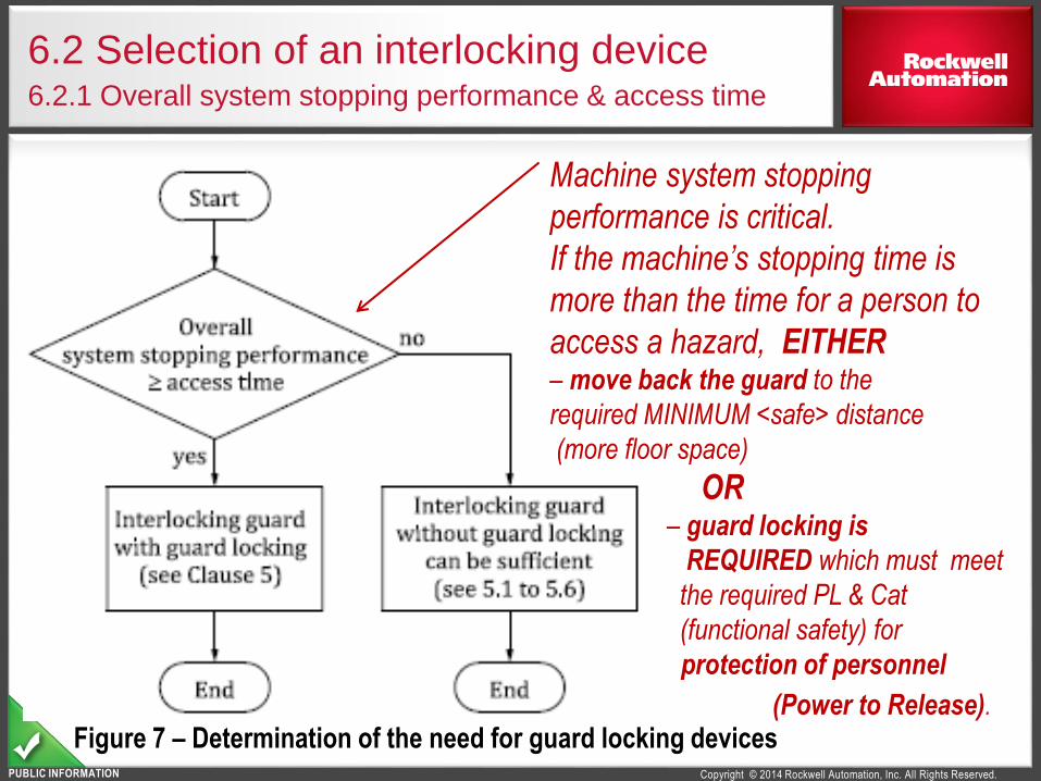
6.2 Selection of an interlocking device6.2.1 Overall system stopping performance & access time
Machine system stopping
performance is critical.
If the machine’s stopping time is
more than the time for a person to
access a hazard, EITHER– move back the guard to the
required MINIMUM <safe> distance
(more floor space)
OR– guard locking is
REQUIRED which must meet
the required PL & Cat
(functional safety) for
protection of personnel
(Power to Release).Figure 7 – Determination of the need for guard locking devices
Copyright © 2014 Rockwell Automation, Inc. All Rights Reserved.PUBLIC INFORMATION
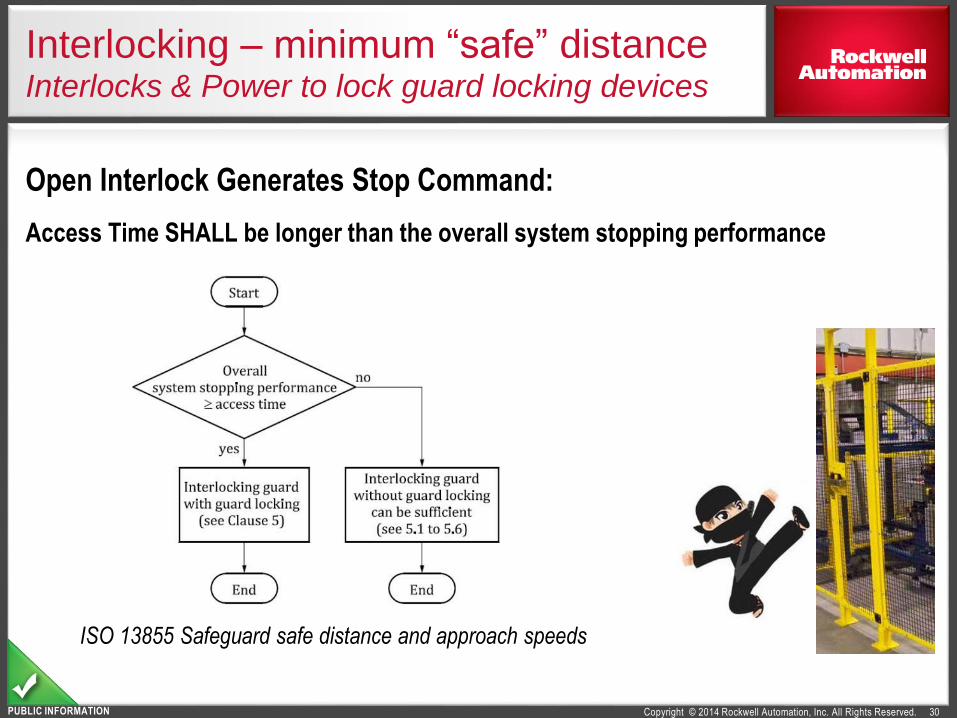
Interlocking – minimum “safe” distanceInterlocks & Power to lock guard locking devices
30
Open Interlock Generates Stop Command:
Access Time SHALL be longer than the overall system stopping performance
ISO 13855 Safeguard safe distance and approach speeds

Copyright © 2014 Rockwell Automation, Inc. All Rights Reserved.PUBLIC INFORMATION
Minimum Safe Distance FormulaRequired for Interlocks
31
ISO 13855:2010 is required by ISO 14119
S = (K x T) + C
S = Minimum (safe) distance between the safeguarding device and the hazard, in mm
K = Speed constant, based on approach speeds of the body or parts of the body (either ≥ 1,600 or 2,000 mm/sec)
T = Overall system stopping time, in seconds (ISO 10218: anticipated worst case)
C = Intrusion distance (Depth penetration factor), in mm
For info: ANSI B11.19-2010, CSA Z432, CSA Z434
Ds = [K x (Ts + Tc + Tr)] + Dpf
Ds = Minimum (safe) distance between the safeguarding device and the hazard, in mm
K = Speed constant, based on approach speeds of the body or parts of the body (≥ 1600 mm/sec)
Ts = Worst anticipated stopping time of the machine or equipment, in seconds
Tc = Worst anticipated response time of the control system, in seconds
Tr = Response time of the protective device, including its interface, in seconds
Dpf = Depth penetration factor (intrusion distance), in millimeters
S

Copyright © 2014 Rockwell Automation, Inc. All Rights Reserved.PUBLIC INFORMATION
Interlocking with Guard Locking
32
Guard Locking Devices:
Protection of People: Shall be A or C – unless not appropriate by Risk Assessment

Copyright © 2014 Rockwell Automation, Inc. All Rights Reserved.PUBLIC INFORMATION
InterlockingWith Guard Locking – Releases
33
Foreseeable Access – as defined by Risk Assessment
Release
Type
Guard
Locking
Safety
Actuated Operating
Release Result Reset Notes
Wh
ere
Aid
sUnlocking
Escape People Inside No
Directly on
Locking
Mechanism
Stop Command
-Emergency and Escape release can be
SAME, if Escape Release Requirements
met (mounted inside)
Emergency People Outside No
Directly on
Locking
Mechanism
Stop Command and
Lock Blocking
Tool,Replacement,
Control System
-Marked for Emergency Only
-Shielded from accidental use
-Emergency and Escape release can be
SAME, if Escape Release Requirements
met (mounted inside)
Auxiliary Process Outside
Tool
or
Key
Stop Command
Tool,Replacement,
Control System
-For Exceptional Use
-Shielded from accidental use

Copyright © 2014 Rockwell Automation, Inc. All Rights Reserved.PUBLIC INFORMATION
Interlocking – Performance Level
34
Control System Requirements:
Interlocks are safety related parts of a control system (ISO 13849-1)
Fault Exclusion of Broken Tongue Actuator
PLd requires full written justification
PLe not justifiable
When Manual Functional Test required to detect accumulation of faults:
PLd = 12 months
PLe = monthly
Guard Door Locking must meet PLr
PLr of unlocking often less than PLr interlock
Lock engaged
Includes release conditions: speed, position, time delay

Copyright © 2014 Rockwell Automation, Inc. All Rights Reserved.PUBLIC INFORMATION
Series Connection
35
Restrictions for series connected contacts (electromechanical)
8.6 Logical series connection of interlocking devices
When interlocking devices with redundant contacts are connected in series the detection of a single fault can be masked by the actuation of any interlocking device connected between the fault and the safety related control system. It could also lead to the unexpected reset from a detected fault condition.
Maximum of 5 dry contact switches in series for PLd - for 1 frequently used guard (ref: ISO TR 24119)
>1/hr <1/hr <1/hr <1/hr <1/hr
Number of frequently used movable guards1
Number of additional movable guards
Masking probability Diagnostic CoverageMaximum
Achievable PL
0
2 to 4 Low > 60 % PL d
5 to 30 Medium > 60 % PL d
> 30 High < 60 % (none) PL c
1
1 Low > 60 % PL d
2 to 4 Medium > 60 % PL d
> 5 High < 60 % (none) PL c
> 1 - High < 60 % (none) PL c1switching frequency greater than once per hour

Copyright © 2014 Rockwell Automation, Inc. All Rights Reserved.PUBLIC INFORMATION
Fault Masking
36
ISO TR 24119 is expected to state…
PLe not be allowed for devices with simple dry contacts connected
in series (the maximum PL will be PLd ).
As it is, one simple switch with dry contacts cannot achieve PLe because fault
exclusion is used for breakage of the tongue actuator/ key.
In systems where fault masking is foreseeable for series connection
of dry (zero voltage) contacts, DC is reduced to NONE and the
system is limited to a maximum of PLc
Monitoring
Safety
Relay
Door 1 Door 2

Copyright © 2014 Rockwell Automation, Inc. All Rights Reserved.PUBLIC INFORMATION
ISO 14119: How are Products Affected?
Safety Switches
Update documentation stating compliance to ISO 14119 by 4/15/2015
Refer to ISO 14119 for interlocking installation and use issues
Type 2: Tongue interlocks & guard locking (except TLSZ & 440G-LZ)
Max PLd when used for guard interlocking (requires fault exclusion)
Limitation of # of switches in series wiring & achieving the required PL
Type 2: Guard locking (except TLSZ & 440G-LZ)
Tested and certified to the new holding force requirements
Type 4: Non-contact interlocks
List actuator coding: low, medium, and high
Only LOW (standard RFID & others) and HIGH (unique RFID)
Type 4: Non-contact sensing for Guard locking (TLSZ, 440G-LZ)
State compliance, holding forces
State PL for both guard position monitoring (interlocking) and lock monitoring
37
Copyright © 2014 Rockwell Automation, Inc. All Rights Reserved.PUBLIC INFORMATION
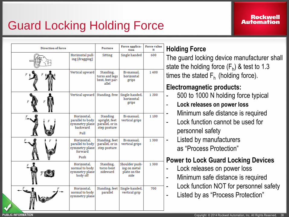
Guard Locking Holding Force
38
Holding Force
The guard locking device manufacturer shall
state the holding force (Fh) & test to 1.3
times the stated Fh (holding force).
Electromagnetic products:- 500 to 1000 N holding force typical
- Lock releases on power loss
- Minimum safe distance is required
- Lock function cannot be used for
personnel safety
- Listed by manufacturers
as “Process Protection”
Power to Lock Guard Locking Devices - Lock releases on power loss
- Minimum safe distance is required
- Lock function NOT for personnel safety
- Listed by as “Process Protection”

Copyright © 2014 Rockwell Automation, Inc. All Rights Reserved.PUBLIC INFORMATION
Summary: Mechanical Design Requirements
39
Minimize motivation to defeat interlock devices:
Installation and Location
Protected from foreseeable damage
Sufficiently rigid to maintain operation
Withstand expected forces: vibration, door slamming
Not used as a door stop, unless impact rating declared by manufacturer
Fastening shall be designed to withstand the locking device holding force
Copyright © 2014 Rockwell Automation, Inc. All Rights Reserved.PUBLIC INFORMATION
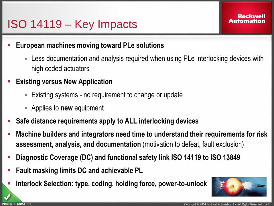
ISO 14119 – Key Impacts
40
European machines moving toward PLe solutions
Less documentation and analysis required when using PLe interlocking devices with
high coded actuators
Existing versus New Application
Existing systems - no requirement to change or update
Applies to new equipment
Safe distance requirements apply to ALL interlocking devices
Machine builders and integrators need time to understand their requirements for risk
assessment, analysis, and documentation (motivation to defeat, fault exclusion)
Diagnostic Coverage (DC) and functional safety link ISO 14119 to ISO 13849
Fault masking limits DC and achievable PL
Interlock Selection: type, coding, holding force, power-to-unlock

Copyright © 2014 Rockwell Automation, Inc. All Rights Reserved.PUBLIC INFORMATION
Four (4) types of interlocking devices
41
Actuation Principle Actuator examplesAbbreviation
(NOT Functional Safety)
MechanicalPhysical
contact
force
uncoded
Rotary cam
Type 1Linear cam
Hinge
coded
Tongue
(shaped actuator) Type 2Trapped-key
Non-
contact
Inductive
uncoded
Suitable ferric metal
Type 3For restrictions, see 7.1a
Magnetic Magnet, solenoid
Capacitive Any suitable object
Ultrasonic Any suitable object
Optic Any suitable object
Magnetic Coded(low,
medium,
high)
Coded magnet
Type 4RFID Coded RFID tag
Optic Optically coded tag
Copyright © 2014 Rockwell Automation, Inc. All Rights Reserved.PUBLIC INFORMATION
Interlocking devices & actuation directionNote direction of travel of the actuator to the switch
Type 1 Type 3 & 4
3 Actuator (cam)
Direction of Opening
1 Guard
5 Actuating
System
6 Output
System
4
Position
Switch
2
Interlocking
Device
1 Guard 1 Guard1 Guard
2 2 255 5
6 66
44
Type 2
CODED
Tongue (actuator) Operated
Guard Not Closed
UNCODED
Cam Operated
Guard Closed
UNCODED or CODED
(low, med, high CODED)
Non-Contact Actuated
Guard Closed
333

Copyright © 2014 Rockwell Automation, Inc. All Rights Reserved.PUBLIC INFORMATION
TYPE 1 - Mechanical - Uncoded
43
Examples
Rotary Cam Annex A.1
Linear Cam Annex A.2, A.4
Hinge Annex A.3
4.1 Overview of interlocking Devices Table 1
Type 1
AbbreviationActuation Principles
Uncoded
Actuator Examples
Mechanical Physical contact / force
Annex A.1
Product?
Mode of operation?
Annex A.2 Annex A.4 Annex A.3

Copyright © 2014 Rockwell Automation, Inc. All Rights Reserved.PUBLIC INFORMATION
TYPE 2 - Mechanical - Coded
44
Annex B.1
Product?
Annex B.2
Examples
Tongue ( shaped Actuator Annex B.1
Trapped key Annex B.2
4.1 Overview of interlocking Devices Table 1
Type 2
AbbreviationActuation Principles
Coded
Actuator Examples
Mechanical Physical contact/force
The standard does not provide all the specificrequirements for trapped key systems

Copyright © 2014 Rockwell Automation, Inc. All Rights Reserved.PUBLIC INFORMATION
Examples
Inductive Suitable ferric metal
Magnetic Magnetic Solenoid
Capacitive any suitable object
Ultrasonic any suitable object
Optic any suitable object
4.1 Overview of interlocking Devices Table 1
Type 3 Annex CNon Contact Uncoded
AbbreviationActuation Principles Actuator Examples
TYPE 3 - Non Contact - Uncoded
45
Annex C
Product?
Annex C
5.4 - Type 3 & 4 devices to meet the requirements of 60947-5-3 proximity deviceswith defined behaviour under fault condition

Copyright © 2014 Rockwell Automation, Inc. All Rights Reserved.PUBLIC INFORMATION
TYPE 4 - Non Contact - Coded
46
Annex D.1
Product?
Examples
Magnetic coded magnet Annex D1
RFID coded RFID tag Annex D2
Optic optically coded tag -
4.1 Overview of interlocking Devices Table 1
Type 4Non Contact Coded
AbbreviationActuation Principles Actuator Examples
Annex D.2

Copyright © 2014 Rockwell Automation, Inc. All Rights Reserved.PUBLIC INFORMATION
Distance to the closest hazard when reaching through or around a guard
47
Example Body
Part
Graphic (upper limbs shown because of
their smaller dimensions, but
table is applicable to both upper
and lower limbs)
Opening (e)
(Smallest Dimension)
Minimum (Safe) Distance Srdoes NOT replace C or Dpf in safety distance formula
Slotted mm
inSquare mm
inRound mm
in
Finger tip
mm
in.
0 < e ≤ 4
0 < e ≤ 0.16
≥ 2
0.08
≥ 2
0.08
≥ 2
0.08
mm
in.
4 < e ≤ 6
0.16 < e ≤ 0.24
≥ 10
0.39
≥ 5
0.20
≥ 5
0.20
mm
in.
6 < e ≤ 8
0.24 < e ≤ 0.31
≥ 20
0.79
≥ 15
0.59
≥ 5
0.20
Finger to knuckle
joint
mm
in.
6 < e ≤ 8
0.24 < e ≤ 0.31
≥ 20
0.79
≥ 15
0.59
≥ 5
0.20
mm
in.
8 < e ≤ 10
0.31 < e ≤ 0.39
≥ 80
3.1
≥ 25
0.98
≥ 20
0.20
Hand
mm
in.
10 < e ≤ 12
0.39 < e ≤ 0.47
≥ 100 ≥ 80 ≥ 80
mm
in.
12 < e ≤ 20
0.47 < e ≤ 0.79
≥ 120 ≥ 120 ≥ 120
mm
in.
20 < e ≤ 30
0.79 < e ≤ 1.2
≥ 850* ≥ 120 ≥ 120
Arm up to junction
with shoulder
mm
in.
30 < e ≤ 40
1.2 < e ≤ 1.6
≥ 850* ≥ 200 ≥ 120
mm
in.
40 < e ≤ 120
1.6 < e ≤ 4.7
≥ 850* ≥ 850* ≥ 850*
OVER (reach over)UPPER
Limb ONLYmm
in.
120 < e
4.7 < eSee Reaching OVER
Requirements
UNDER
(reach under the
guard)
Upper or
Lower Limbsmm
in.
180 < e
7 < e
Use SLOTTED column above. Additional safeguarding required if opening
greater than 180mm
Source: ISO 13857:2008, 4.2.4.1, Table 4, with RIA R15.406 addition of “Over” and “Under” rows
The
dim
ensi
on o
f the
ope
ning
, e, c
orre
spon
ds to
the
side
of a
squ
are
open
ing,
the
diam
eter
of a
rou
nd o
peni
ng a
nd th
e na
rrow
est d
imen
sion
of a
slo
t ope
ning
* P
er A
NS
IB
11.1
9, C
SA
Z43
4 &
CS
A
Z43
2: a
rm r
each
is 9
15 m
m (
36 in
.)

Copyright © 2014 Rockwell Automation, Inc. All Rights Reserved.PUBLIC INFORMATION
Reaching OVER a guard…
48
High Risk:For hazard zones above 2,500 mm (98 in.) (reaching upwards), H shall be at least 2,700 mm (106 in.)
Low Risk: For hazard zones above 2,500 mm (98 in.) (reaching upwards), H shall be at least 2,500 mm (98 in.)
[ISO 13857:2008]

Copyright © 2014 Rockwell Automation, Inc. All Rights Reserved.PUBLIC INFORMATION
Reach OVER – HIGH RISK situations
49
Height of
Hazard area
Height of Protective Structure (b) Dimensions in mm
1,000 1,200 1,400 1,600 1,800 2,000 2,200 2,400 2,500 2,700
(a) Horizontal minimum (safety) distance to hazard zone (c) in HIGH RISK situations
2,700 0 0 0 0 0 0 0 0 0 0
2,600 900 800 700 600 600 500 400 300 100 0
2,400 1,100 1,000 900 800 700 600 400 300 100 0
2,200 1,300 1,200 1,000 900 800 600 400 300 0 0
2,000 1,400 1,300 1,100 900 800 600 400 0 0 0
1,800 1,500 1,400 1,100 900 800 600 0 0 0 0
1,600 1,500 1,400 1,100 900 800 500 0 0 0 0
1,400 1,500 1,400 1,100 900 800 0 0 0 0 0
1,200 1,500 1,400 1,100 900 700 0 0 0 0 0
1,000 1,500 1,400 1,000 800 0 0 0 0 0 0
800 1,500 1,300 900 600 0 0 0 0 0 0
600 1,400 1,300 800 0 0 0 0 0 0 0
400 1,400 1,200 400 0 0 0 0 0 0 0
200 1,200 900 0 0 0 0 0 0 0 0
0 1,100 500 0 0 0 0 0 0 0 0
[ISO 13857:2008, Table 2]NOTE – Do not interpolate numbers. Use the figures that will result in a more conservative outcome.
For example, if the height of the hazard area (a) is 1,300 mm (51 in.), then use 1,400 mm (55 in.).
If the protective structure height (b) is 1,900 mm (75 in.), use the 1,800 mm (72 in.) column for the protective height structure.
Copyright © 2014 Rockwell Automation, Inc. All Rights Reserved.PUBLIC INFORMATION
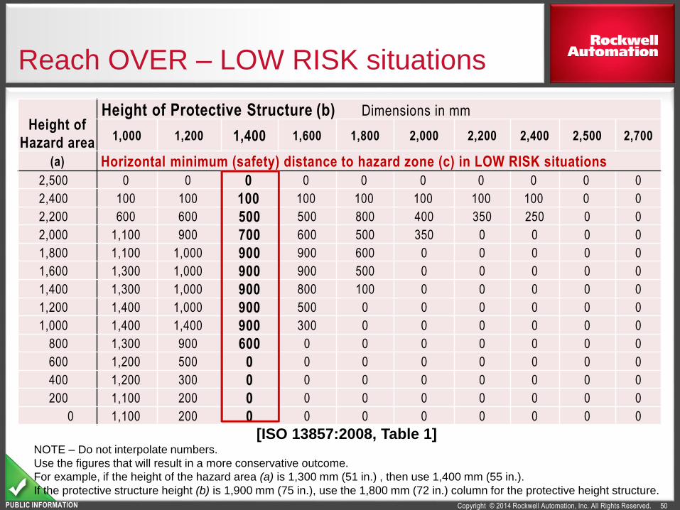
Reach OVER – LOW RISK situations
50
Height of
Hazard area
Height of Protective Structure (b) Dimensions in mm
1,000 1,200 1,400 1,600 1,800 2,000 2,200 2,400 2,500 2,700
(a) Horizontal minimum (safety) distance to hazard zone (c) in LOW RISK situations
2,500 0 0 0 0 0 0 0 0 0 0
2,400 100 100 100 100 100 100 100 100 0 0
2,200 600 600 500 500 800 400 350 250 0 0
2,000 1,100 900 700 600 500 350 0 0 0 0
1,800 1,100 1,000 900 900 600 0 0 0 0 0
1,600 1,300 1,000 900 900 500 0 0 0 0 0
1,400 1,300 1,000 900 800 100 0 0 0 0 0
1,200 1,400 1,000 900 500 0 0 0 0 0 0
1,000 1,400 1,400 900 300 0 0 0 0 0 0
800 1,300 900 600 0 0 0 0 0 0 0
600 1,200 500 0 0 0 0 0 0 0 0
400 1,200 300 0 0 0 0 0 0 0 0
200 1,100 200 0 0 0 0 0 0 0 0
0 1,100 200 0 0 0 0 0 0 0 0
[ISO 13857:2008, Table 1]NOTE – Do not interpolate numbers.
Use the figures that will result in a more conservative outcome.
For example, if the height of the hazard area (a) is 1,300 mm (51 in.) , then use 1,400 mm (55 in.).
If the protective structure height (b) is 1,900 mm (75 in.), use the 1,800 mm (72 in.) column for the protective height structure.

Copyright © 2014 Rockwell Automation, Inc. All Rights Reserved.PUBLIC INFORMATION
Perimeter Guard (reach over, reach under)
EXAMPLE R15.06-1999ISO 10218
R15.06-2012CSA Z434
Lower Dimension, max 300mm (12”) 180mm ( 7”) 150mm (6”)
Upper Dimension, min 1500mm (60”) 1400mm (55”) 1800mm (72”)
Lower Dimension Upper Dimension
Presumes no hazard can be reached over the guard or under the guard (by arm or leg). This means no hazard within 1100mm for High Risk (over and under). See ISO 13857.
If hazard can be reached, the dimensions change.

Copyright © 2014 Rockwell Automation, Inc. All Rights Reserved.PUBLIC INFORMATION
Minimum (Safe) Distance Formularequired for the “interlocked portion of the guard”
52
ISO 13855:2010 is required by ISO 14119
S = (K x T) + C Where:
S = Minimum (safe) distance between the safeguarding device and the hazard, in mm
K = Speed constant, based on approach speeds of the body or parts of the body (either ≥ 1,600 or 2,000 mm/sec)
T = Overall system stopping time, in seconds (anticipated worst case – see standard for details)
C = Intrusion distance (Depth penetration factor), in mm
For info: ANSI B11.19-2010, RIA R15.06-1999, CSA Z432 & CSA Z434
Ds = [K x (Ts + Tc + Tr)] + Dpf Where:
Ds = Minimum (safe) distance between the safeguarding device and the hazard, in mm
K = Speed constant, based on approach speeds of the body or parts of the body (≥ 1600 mm/sec)
Ts = Worst anticipated stopping time of the machine or equipment, in seconds
Tc = Worst anticipated response time of the control system, in seconds
Tr = Response time of the protective device, including its interface, in seconds
Dpf = Depth penetration factor (intrusion distance), in millimeters
S
not all guarding shown

Copyright © 2014 Rockwell Automation, Inc. All Rights Reserved.PUBLIC INFORMATION
Various guard locking requirements…
53
Definitions
3.4 Guard Locking Device: a device intended to lock a guard in the
closed position and linked to the control system
3.5 Interlocking Guard with Guard Locking
3.24 Prevention of inadvertent locking position (G3.3.)
3.25 Emergency release of guard locking (from outside) (5.7.2, 5.7.5.3)
3.26 Auxiliary release of guard locking (from outside) (5.7.5.4)
3.27 Escape release of guard locking (from inside) (5.7.5.2)
3.28 Guard locking for protection of a person
3.29 Guard locking for protection of the process (or production)
5.7 Additional requirements on guard locking devices: manufacturer of
device, machine builder, integrator of device See 5.7.6: requirement that fastening must also withstand holding force rating.

Copyright © 2014 Rockwell Automation, Inc. All Rights Reserved.
www.rockwellautomation.com
Follow ROKAutomation on Facebook & Twitter.Connect with us on LinkedIn.
Rev 5058-CO900F
PUBLIC INFORMATION
Questions?