Embed Size (px)
Citation preview

The Development of Structural Health Monitoring (SHM) Procedures for the Structural Integrity and Maintenance Repair of Offshore Ageing Pipelines
Mahadi ABD MURAD Department of Applied Mechanics, School of Engineering
Cranfield University, United Kingdom
Abstract. In the oil and gas industry, pipelines are essential components of the energy supply chain. This infrastructure will still need to perform for many more decades, as the world demand for oil and gas continues to increase. Oil and gas pipeline operations are considered one of the highest risk activities in the industry. Any failure of a pipeline system will cause a significant impact to the environment and economy.
However, many oil and gas pipelines are nearing the end of their design life but have many more years of production left. Despite the best designed and well maintained pipelines, the unavoidable defects such as metal loss due to corrosion, erosion, cracks and others mean structural integrity can be compromised.
Operators need to be aware of the effects of these defects on their pipelines, and more importantly to be able to assess and monitor structural integrity. Pipeline monitoring is frequently restricted to visual inspection and mass or flow measurements leading to very limited capabilities to detect and locate pipeline failures such as leakages. As a result, pipeline failures are usually noticed only when the output flow is affected or when they have severe effects on the surrounding environment leading to potentially costly situations.
The integrity assessment of oil and gas pipelines is well developed. Formerly, inspection and maintenance have been carried out at predefined intervals in order to ensure structural integrity. Today with the increasing availability of advanced sensor methods, pipeline operators have available very powerful and cost-effective tools. Structural Health Monitoring (SHM) can be used for rapid condition screening and aims to provide, in near real time, reliable information regarding the integrity of the structure.
This paper reviews the development of SHM procedures in particular, introducing optical fiber sensors (FBG) and electrical sensors (electrical gauges) embedded between composite wrapping and parent material (i.e. steel pipelines) that contain identified defects. A methodology for structural integrity and pipeline maintenance and repair is presented in this paper.
4th European-American Workshop on Reliability of NDE - Th.2.A.1
1
ww
w.ndt.net/index.php?id=
8332

1. INTRODUCTION
In today’s global competitive market, pipeline operators face challenging performance requirements whereby the product must be delivered per contractual obligations and in a safe and cost effective manner. As the public scrutiny of the pipeline industry increases, security and environmental issues have to manage and demonstrate the best performance and confidence. To meet safety and environmental regulations, and operate cost effectively- striking the right balance between operational costs versus performance and potential failures are the main challenges 1.
In addition, one of the most important problems in science and engineering at the beginning of 21st century is ensuring the reliability and safety of operating gas and oil pipelines. The large number of pipe ruptures in recent years has led to loss of human life, the destruction of dwellings and industrial facilities, and huge environmental losses 2.
Thodi, et al.3 indicate that Hydrocarbon leaks pose a serious threat to the safety of operation in chemical installations. Studies indicate that corrosion is the principal cause of about 15% of leakage occurrences and accounts for 21% of failures in submarine gas pipelines. Erosion corrosion modes account for 24.6% of pipe leakages in process plants. Moreover, 40% of the accidental hydrocarbon releases to the environment are corrosion related.
However, there is an increasing requirement around the world to defer the replacement of ageing pipelines. Pipelines reaching the end of or exceeding their original design life are likely to have their life extended. The composite sleeve repair system has been introduced in order to extend the life of an old or ageing pipe for many years without interrupting the oil supply 4.
In the North Sea as highlighted by Clausard5, many assets have been in operation for up to 20 years and have almost reached their design lives of 25-30 years. Kotrechko et al 6 in their study also mention that the operation period of the major part of the existing pipelines can be estimated as 20-30 years. This long operation leads not only to the appearance of macro defects but also affects the mechanical properties of pipelines. It is necessary to determine their current engineering state and predict the residual service life since the ability to ensure the integrity of ageing assets and extending safe remaining life has become more critical.
A lot of effort has been put in by many companies, individuals and others in upholding the integrity of ageing pipelines. The key success of realizing the extension of pipeline life is counting on the systematic strategy on how to develop and implement integrity management programs by each pipeline operator 7. Based on the data generated by the inspection programme for instance, an operator can go forward and make decisions related to the current and future integrity of a pipeline, remaining life assessment and appropriate preventative maintenance and inspection activities to maintain the design plan for the pipeline and others 5.
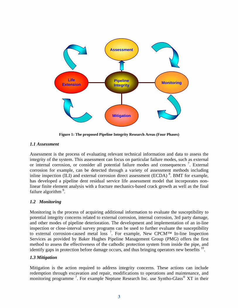
The status of integrity programs is a function of operational experience, corporate philosophy and mandates, and asset management. Thus, there is no single approach that provides the best solution for all pipeline systems. Four components namely Assessment, Monitoring, Mitigation, and Life Extension provide the means to develop a comprehensive integrity management program tailored to meet specific needs and situations for each pipeline operator and pipeline system 7. In fact these four components have also become the main focus of my research study in the pipeline integrity and they are illustrated in Figure 1 below.
2
Life Extension
Mitigation
Monitoring
Assessment
Pipeline Integrity
Figure 1: The proposed Pipeline Integrity Research Areas (Four Phases)
1.1 Assessment
Assessment is the process of evaluating relevant technical information and data to assess the integrity of the system. This assessment can focus on particular failure modes, such as external or internal corrosion, or consider all potential failure modes and consequences 7. External corrosion for example, can be detected through a variety of assessment methods including inline inspection (ILI) and external corrosion direct assessment (ECDA) 8. BMT for example, has developed a pipeline dent residual service life assessment model that incorporates non-linear finite element analysis with a fracture mechanics-based crack growth as well as the final failure algorithm 9.
1.2 Monitoring
Monitoring is the process of acquiring additional information to evaluate the susceptibility to potential integrity concerns related to external corrosion, internal corrosion, 3rd party damage, and other modes of pipeline deterioration. The development and implementation of an in-line inspection or close-interval survey programs can be used to further evaluate the susceptibility to external corrosion-caused metal loss 7. For example, New CPCM™ In-line Inspection Services as provided by Baker Hughes Pipeline Management Group (PMG) offers the first method to assess the effectiveness of the cathodic protection system from inside the pipe, and identify gaps in protection before damage occurs, and thus bringing operators new benefits 10.
1.3 Mitigation
Mitigation is the action required to address integrity concerns. These actions can include redemption through excavation and repair, modifications to operations and maintenance, and monitoring programme 7. For example Neptune Research Inc. use Syntho-Glass® XT in their
3
pipeline repair works which complies to ASME PCC-2, DOT and API570. This unique pre-impregnated, bi-directional fiberglass composite is used to repair and reinforce both internal and external corrosion damage 11.
1.4 Life Extension
tify the most appropriate strategy for continued monito
d localization of leakage and or ground movem
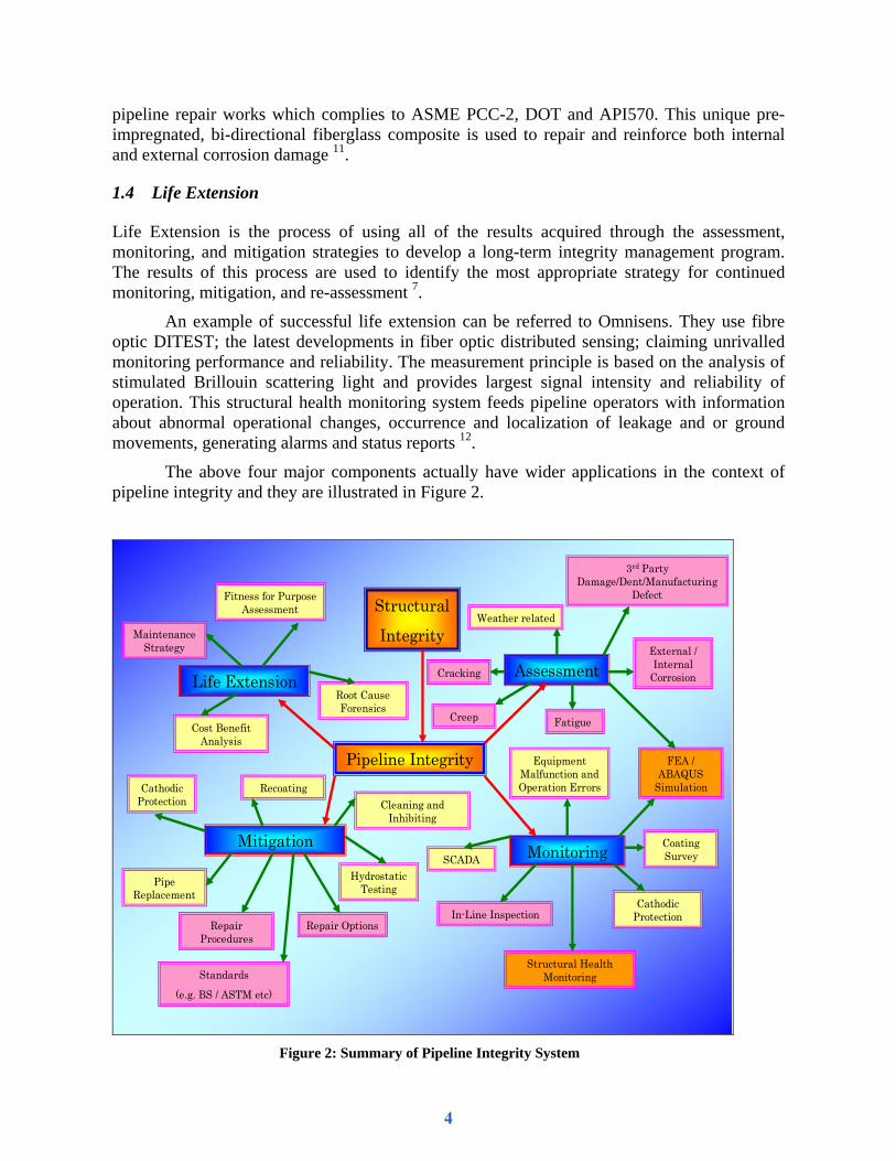
ve wider applications in the context of ipeline integrity and they are illustrated in Figure 2.
Life Extension is the process of using all of the results acquired through the assessment, monitoring, and mitigation strategies to develop a long-term integrity management program. The results of this process are used to iden
ring, mitigation, and re-assessment 7.
An example of successful life extension can be referred to Omnisens. They use fibre optic DITEST; the latest developments in fiber optic distributed sensing; claiming unrivalled monitoring performance and reliability. The measurement principle is based on the analysis of stimulated Brillouin scattering light and provides largest signal intensity and reliability of operation. This structural health monitoring system feeds pipeline operators with information about abnormal operational changes, occurrence an
ents, generating alarms and status reports 12.
The above four major components actually hap
Pipeline Integrity
Assessment
MonitoringMitigation
Life Extension
Structural Integrity
Weather related
External / Internal
Corrosion
3rd Party Damage/Dent/Manufacturing
Defect
Fatigue
Cracking
FEA / ABAQUS
Simulation
Equipment Malfunction and Operation Errors
SCADA
In-Line Inspection
Structural Health Monitoring
CathodicProtection
Coating Survey
Repair Procedures
Standards
(e.g. BS / ASTM etc)
Repair Options
Hydrostatic TestingPipe
Replacement
CathodicProtection
RecoatingCleaning and
Inhibiting
Cost Benefit Analysis
Root Cause Forensics
Fitness for Purpose Assessment
Maintenance Strategy
Creep
Figure 2: Summary of Pipeline Integrity System
4
2. STRUCTURAL HEALTH MONITORING (SHM)
an array of sensors, the extraction of damage-sensitive
in and Raman scattering and these systems have been improved in terms of spatial, temperature and strain
asurement time, data processing and system cost.
Sensors
literature review
in my research study, I would be using optical fibre sensor particularly Fibre Bragg Grating (FBG) and reasons for that selection are further explained in the following
the literature study by Fixter and Caroline 14, the types of optical sensors are identified as llows:
n optical fibre
ors
)
2. 1 Definitions of SHM
Structural Health Monitoring (SHM) can be defined as the acquisition of information to enable the diagnosis and prognosis of structural integrity. According to Chung DLL 13, SHM refers to the monitoring of the integrity of a structure for the purpose of hazard mitigation, whether the hazard is due to live load, ocean, waves, earthquake, fatigue, heat, ageing and other factors. This process involves the observation of a system over time using periodically sampled dynamic response measurements fromfeatures from these measurements, and the statistical analysis of these features to determine the current state of the system’s health 14. In addition, Sohn15 states that SHM has the ability to perform its intended function in light of the inevitable ageing and degradation resulting from operational environments. Inaudi and Glisic16 describe the SHM as one of the most powerful management tools and becomes important the civil engineering community. A typical health monitoring system is composed of a network of sensors that measure the parameters relevant to the state of the structure and its environment. The most developed distributed fibre optics are based on Brillou
resolution, distance range, me
2.2 Optical Fibre
2.2.1 Introduction
In order to develop SHM techniques for a pipeline repair system, I have to study the scope and capability of the most suitable sensors in my experimental work later on. In this
, I have made some comparisons between optical fibre and electrical sensors and notice that both of these technologies contribute towards SHM.
The selection of these sensors actually depends on several factors such environment, cost, and etc. Hence,
section of this paper.
2.2.2 Types of optical fibre sensors
Info
i) Triboluminescent Sensors
ii) High Birefringence damage detectio
iii) Multicore Optical Fibre Sens
iv) Acoustic Emission Sensors
v) Fused Tapered Coupler (FTC
vi) E-glass Fibre Light Guides
5
vii) Surface Mounted Optical Fibres
viii) Embedded Optical Fibres
the core of a single mode fibre, as a result of the interference pattern produc
e by hanging the angle between the interfering beams of the lasers when creating the grating 14.
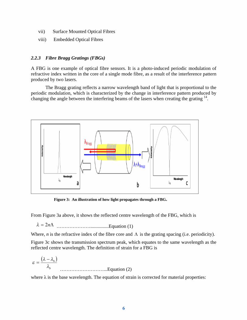
2.2.3 Fibre Bragg Gratings (FBGs)
A FBG is one example of optical fibre sensors. It is a photo-induced periodic modulation of refractive index written in
ed by two lasers.
The Bragg grating reflects a narrow wavelength band of light that is proportional to the periodic modulation, which is characterized by the change in interference pattern produc d c
Figure 3: An illustration of how light propagates through a FBG.
From Figure avelength of the FBG, which is
3a above, it shows the reflected centre w
…………………...............Equation (1)
Where, n is the refractive index of the fibre core and Λ is the grating spacing (i.e. periodicity).
Figure 3c shows the transmission spectrum peak, which equates to the same wavelength as the reflected centre wavelength. The definition of strain for a FBG is
………………………...Equation (2)
where λ is the base wavelength. The equation of strain is corrected for material properties:
6

……..…Equation (3)
here, K is a function of the Poisson’s ratio, strain-optic constants of the fibre, and refractive efficient and ∆T is the temperature change. Typical wavelength rain and 10 pm/K for the temperature of Bragg gratings around
1.53µm
rot sensor and this sensor is developed as AE sensors, where the sensor is illuminated using a laser at a fixed wavelength. When the stress wave generated by the AE propagates through the composite to the sensor, it produces small mechanical strain changes at the air gap of the sensor, which cause the laser light to fluctuate. Figure 4 illustrates how the FBG sensor works.
Windex, ξ is the thermal optic coshifts are 1.2pm/(µm/m) for st
.
2.2.4 FBG sensor functions A simple explanation on how the sensor works can be referred to the literature study
by Fixter and Caroline 14. They used a Fabry-Pe
Figure 4: Fibre Bragg Grating sensor and multiplexing principle 17
2.2.5 FBG sensor methods The dominant current methods for fibre Bragg grating wavelength interrogation are reviewed by Todd et al. 18 as follows;
i) WDM interferometry
7

ii) Tunable filter that includes both scanning Fabry–Perot (SFP) and acousto-optic (AOTF)
iii) CCD or prism technique
erometric
ities of Fibre Bragg Gratings (FBGs) and other optical fibre sensors
Asundi justif
rain gauges, FBGs cannot be positioned directly on top of each
y of real-time monitoring of the fatigue damage of
rimetric sensors (FOPSs) and fiber optic curvature sensors (FOCSs) can both be used for on-line damage sensing and monitoring on any specimen with different cracks.
iv) A newer hybrid method utilizing Fabry–Perot and March Zender interftechniques.
2.2.6 CapabilIn the literature studies by Fixter and Caroline 14 and Rao et al 19, Lee et al 20, and Ma and
21, they state the above sensors have their own capabilities based on the following ications;
i) Chirped FBGs (CFBGs) sensor for instance is versatile and can be used to detect transverse cracking which is at a 90º ply interface and delamination growth in Glass Reinforced Plastic (GRP).
ii) Whenever AE is emitted in bursts, it propagates through the structure, giving a pre - warning that damage is initiating. Conventionally, piezoceramic transducer sensors are used to monitor these events. However, optical fibres are proving to be a viable alternative.
iii) FBG sensors are more durable and sensitive than conventional foil strain gauges based on the composite wing of a mini air vehicle (MAV) experiment. FBG sensors are as good as rosette strain gauges in strain measurement and so are suitable for structural health monitoring for large structures.
iv) FBGs measure strain, but a distribution of FBGs can be used to detect impact events in real time, by measuring both the strain drop-off and time delay in the strain changes between the sensors. By using the difference in arrival time of the strain response, the position of the impact event can be determined.
v) Unlike electrical stother, in the same position on a fibre. However, a rosette formation of FBGs can be used to derive more than one orientation of strain measurement near one point. This concept has been used extensively for surface mounting (where the micro-bending can be controlled)
vi) The use of FBGs to monitor cure processes highlights the potential of FBGs to be integrated into as structure for the whole of its life. Embedded FBGs could be used to monitor the structure through its fabrication processes, during qualification tests, and used in SHM.
vii) In order to evaluate the feasibilitcomposite laminates under fatigue loading, embedded intensity-based optical fiber (IBOF) sensors are used. Since the continuous damage assessment cannot be made in situ during the service of the structures by all the NDE techniques, optical fiber (OF) sensors have been applied.
viii) The surface mounted fiber optic pola
8

2.2.7 Conditions of Fibre Bragg Grating (FBG)
One of the conditions of FBG that has to be made clear before using it is that the sensors can not measure two different parameters at the same time and position. Since the wavelength of a FBG shifts with temperature and strain, in real environments and on real structures, both of these will be varying. However, there is a requirement that one is measured independently of the other. One technique for measuring only one parameter is to effectively null the other. For xample, if a strain measurement is required, then a dummy FBG shall measure the effect of
14
TRATEGY FOR SHM EXPERIMENTAL WORK
nce (ACPD) is another good exampl
idth and lar
ill also be further studied and they function as back-up techniques which may be sed in this experiment later if any technically unsolved problem arises with this fibre optic pplication.
etemperature at the same position .
3. PLANNING S
3.1. Introduction There have been many research techniques in nondestructive testing and monitoring especially in the study of plastic deformation and fracture mechanics of the structure. For example acoustic emission has been successfully applied to the field tests. High sensitivity transducers using PZT-5A piezoelectric have been used to detect the elastic wave which propagates through the material 22. Alternating Current Potential Differe
e of measuring the crack sizing in terms of depth and length, and allows the cracks being monitored in a non-destructive manner during testing 23.
Fibre optic sensors will be used since they offer numerous advantages in terms of low inertia, high speed, immunity to electromagnetic interference, nonelectrical contact to the sensing region and intrinsically safe. At least five modulation techniques have been identified such as intensity, phase, frequency, colour and polarization 24. Under various options of fibre optics, Fibre Bragg Grating (FBG) will be applied in this experiment. Despite 18 claims that FBG have a number of advantages over other sensors in their paper such as immunity to electromagnetic noise, negligible weight penalty, extremely high resolution, large bandw
ge multiplexing capability, even with heterogeneous sensor types (e.g. strain gauges and accelerometers) yet this sensor will be studied extensively prior to starting the experiment.
For SHM experimental work, FBG using Wavelength Division Multiplexing equipment (WDM) as referred to Figure 5; expected to be a best technique in principle, would be chosen after knowing its potentials from previous literature studies. However, Piezoelectric transducer and ACPD wua
9
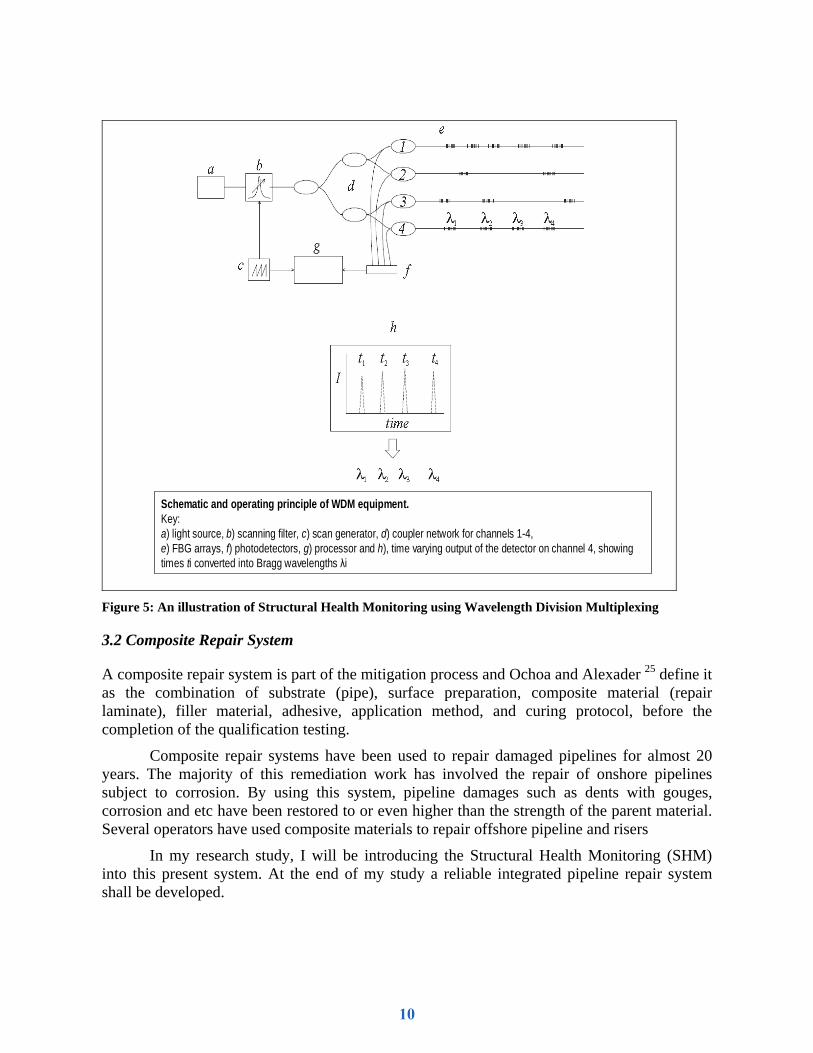
Schematic and operating principle of WDM equipment. Key: a) light source, b) scanning filter, c) scan generator, d) coupler network for channels 1-4, e) FBG arrays, f) photodetectors, g) processor and h), time varying output of the detector on channel 4, showing times ti converted into Bragg wavelengths λi
Figure 5: An illustration of Structural Health Monitoring using Wavelength Division Multiplexing
plication method, and curing protocol, before the comple
material. Severa
tem. At the end of my study a reliable integrated pipeline repair system hall be developed.
3.2 Composite Repair System
A composite repair system is part of the mitigation process and Ochoa and Alexader 25 define it as the combination of substrate (pipe), surface preparation, composite material (repair laminate), filler material, adhesive, ap
tion of the qualification testing.
Composite repair systems have been used to repair damaged pipelines for almost 20 years. The majority of this remediation work has involved the repair of onshore pipelines subject to corrosion. By using this system, pipeline damages such as dents with gouges, corrosion and etc have been restored to or even higher than the strength of the parent
l operators have used composite materials to repair offshore pipeline and risers
In my research study, I will be introducing the Structural Health Monitoring (SHM) into this present syss
10
3.3 The Methodology of Large Scale Experiment
There are 3 types of API 5L Grade B pipes namely Pipe A, B, and C as referred to the proposed general assembly of experimental test set-up (refer to Figure 6 and 7). Pipe B is further divided into 2 zones namely zone 1 and 2. Zone 1 is where the sensor (i.e. using Smart Tape form Smart Fibers Ltd) is patched directly onto the pipe surface which has crack or corrosion and the locations of the sensor remain there throughout all tests. The same locations of sensors are identified in zone 2 but for this zone, the position of sensors will be different with respect to the different technique and its procedure. The reason for zone 1 is to provide some comparisons of measured values obtained in zone 2. In this experiment, there will be only two different products of composite wrap being introduced. Product A refers to Carbon Fibre with Epoxy Matrix and Product B refers to E Glass Fibre with Epoxy Matrix.
In order to determine the best and reliable SHM measuring techniques, 6 tests have been proposed for this experiment. For the first technique, its procedure is defined by placing the sensor directly on the identified defect beneath the epoxy putty of the composite wrap. For the second technique, the sensor is embedded in the epoxy putty itself and the third technique is slightly difficult because the sensor will be embedded between the fiber layers. However, the previous successful research studies particularly discussing the methods of embedding the sensor at different orientation of the fiber will be referred and this will save a lot of times later.
In order to realize the above processes, pressure and temperature will be used as the main controlled parameters in this experiment. By referring to the general assembly of the test set-up, normal water will be used as a medium in the pipe and will be pressurized by the manual pump and heated up by the heating element system. 4 tests will be carried out under pressure against strain at constant temperature of 25 ºC. The operating pressure will be varying from 5 to 30 bars.
The remaining two tests will be performed under strain rate against temperature at a constant pressure of 20 bars. Normally, the working pressure for oil and gas pipeline on site is between 5 to 30 bars. The temperature will be varying from 5 ºC up to 60 ºC. The tabulated readings will be plotted in the graphs of Pressure against Strain and Strain Rate against Temperature before further detailed analyses are being carried out. The tested specimens of each test can also be sent to the machine shop to cut into smaller specimens for the purpose of hardness and etc. The mechanics of microstructure at zone 1 and 2 can also be analyzed in the metallurgical laboratory.
11
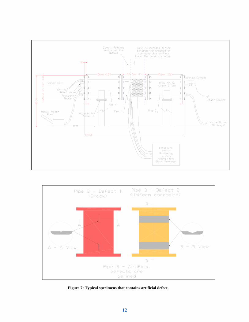
Figure 6: General assembly of the experimental test set-up
Figure 7: Typical specimens that contains artificial defect.
12

4. THE DEVELOPMENT OF INTEGRATED PIPELINE REPAIR
The below figure summarizes the whole idea of the thesis research which is considered as one of the most innovative systems of integrated pipeline repair strategies.
Figure 8: The Methodology of Integrated Pipeline Repair System
5. CONCLUSIONS
A detailed literature review has been conducted into pipeline integrity subject that consists of the four main components namely assessment, monitoring, mitigation and life extension. Under these sections, topics such as SHM, sensors (includes FBGs), composite repair system have been reviewed. A detailed experimental plan has been discussed in terms of large scale development plans, and the whole idea of the thesis research has been summarized in the development of integrated pipeline repair.
13

References: 1. www.dnvsoftware.com (2006), ORBIT Pipeline Integrity, available at:
http://www.dnv.com/binaries/orbit+pipelineintegrity_brochure_tcm4-159685.pdf (accessed December 27, 2008).
2. Kaminskii, A. A. and Bastun, V. N. (1997), "Methods of Determining the Stress-Strain State and Fracture Toughness of Gas and Oil Line Pipe", International Applied Mechanics, vol. 33, no. 8, pp. 595-618.
3. Thodi, P., Khan, F. and Haddara, M. (2008), "The Selection of Corrosion prior Distributions for Risk Based-Integriy Modeling", Stoch Environ Res Risk Assess-Springer, vol. DOI 10.1007/s00477, no. 008-0259-X, pp. 1-17.
4. Alexander's Gas & Oil Connections, ( January 17, 2005), Petra Perdana believes oil and gas sector is bright, Volume 10, Issue 1 ed., Star Publications, http://www.gasandoil.com/goc/company/cns50323.htm.
5. Clausard, C. (2006), Pipeline integrity Management Strategy for Aging Offshore Pipelines, Pigging Products and Services Association,
http://www.ppsa-online.com/papers/2006-Aberdeen-7-Clausard.pdf. 6. Kotrechko, S. A., Krasovskii, A. Y., Meshkov, Y. Y., Mettus, G. S., Polushkin, Y. A. and
Torop, V. M. (2002), "Influence of Long Term Operation on the Toughness of 17GS Pipeline Steel", Strength of Materials, vol. 34, no. 6, pp. 541-547.
7. www.CCTecnologies.com (2008), Pipeline Integrity Management, available at: http://cctechnologies.com/services/pipelineintegrity/index.htm (accessed December 26, 2008).
8. Amend, B. and Structural Integrity Associates, I., ( March 2009), New Soil Corrosiveness and External Corrosion Rate Mode, Volume No 236, Number 3 ed., Pipeline & Gas Journal, Houston, Texas.
9. BMT Fleet Technology (2005), Pipeline Structural Integrity Assessment, Business Briefing: Exploration & Production: The Oil & Gas Review 2004, Touch Briefings, http://www.touchbriefings.com/download.cfm?step=3&fileID=3550.
10. Janda, D. and Baker Hughes Inc., ( March 2009), A Revolution Proclaimed In Cathodic Potection Assessment, Volume No 236, Number 3 ed., Pipeline & Gas Journal, Houston Texas.
11. Neptune Research Inc. (2009), Syntho-Glass XT XtremeStrength Fiberglass Composite System 2X Conventional Strength, available at: http://www.neptuneresearch.com/products/glass.html (accessed April 2009).
12. OMNISONS (2007), Protect Your Pipeline with Omnisens DITEST-AIM Fiber Optic Monitoring Solution, available at: http://www.omnisens.ch/ditest/321-company.php (accessed November 2008, 26).
13. Chung DLL (2001), "Structural Health Monitoring by Electrical Resistance Measurement", Full, vol. 10, no. Smart Mater. Struct; (2001) 624–636, pp. 624-631, 634.
14. Fixter, L. and Caroline, W. (2006), State of the Art Review - Structural Health Monitoring, Qinetic/S&DU/T&P/E&M/TR0601122, Qinetic and SMART.mat, http://amf.globalwatchonline.com/epicentric_portal/binary/com.epicentric.contentmanagement.servlet.ContentDeliveryServlet/AMF/smartmat/locked_SHM%20SMART_mat%20v12.pdf.
15. Sohn, H. (2007), "Effects of environmental and operational variability on structural health monitoring", Philosophical transactions.Series A, Mathematical, physical, and engineering sciences, vol. 365, no. 1851, pp. 539-560.
14

16. Inaudi, D. and Glisic, B. (2006), "Distributed fiber optic strain and temperature sensing for structural health monitoring", Th Third Intrnational Conference on Bridge Maintenance, Safety and Management, 16-19 July 2006, Porto Portugal, IABMAS, Portugal.
17. Ecke, W. (2008), Application of Fibre Bragg Grating Sensors, OFS-19 Tutorial, Insitute of Photonic Technology (IPHT) Jena, Germany.
18. Todd, M. D., Nichols, J. M., Trickey, S. T., Seaver, M., Nichols, C. J. and Virgin, L. N. (2007), "Bragg grating-based fibre optic sensors in structural health monitoring", Philosophical transactions.Series A, Mathematical, physical, and engineering sciences, vol. 365, no. 1851, pp. 317-343.
19. Rao, M. B., Bhat, M. R., Murthy, C. R. L., Madhav, K. Y. and Asokan, S. (2006), "Structural Health Monitoring (SHM) Using Strain Gauges, PVDF Film and Fiber Bragg Grating (FBG) Sensors: A Comparative Study", Proc. National Seminar on Non-Destructive Evaluation, Dec 7 - 9, 2006, Hyderabad India, Indian Society for Non-Destructive Testing.
20. Lee, D. C., Lee, J. J., Kwon, I. B. and Seo, D. C. (2001), "Monitoring of fatigue damage of composite structures by using embedded intensity-based optical fiber sensors", Institute of Physics Publishing, Smart Mater. Struct., [Online], vol. 10, no. PII:S0964-1726(01)20971-9, pp. January 2009 available at: www.iop.org/Journals/sm.
21. Ma, J. and Asundi, A. (2001), "Structural health monitoring using a fiber optic polarimetric sensor and a fiber optic curvature sensor - Static and dynamic test", Institute of Physics Publishing, Smart Mater. Struct., vol. 10, no. S0964-1726(01)19025-7, pp. 181-188-www.iop.org/Journals/sm.
22. Hutton, P. H. and Ord, R. N. (1970), "Acoustic Emission", in Sharpe, R. S. (ed.) Research Technique in Non Destructive Testing, Academic Press, London, pp. Chapter 1.
23. Brennan, F. P., Ngiam, S. S. and Lee, C. W. (March 2007), " An experimental and analytical study of fatigue crack shape control by cold working", Science Direct Engineering Fracture Mechanics, [Online], vol. 75, , pp. April 2009-355-363 available at: www.sciencedirect.com.
24. Culshaw, B. (1984), "Fibre Optic Sensing Technique", in Sharpe, R. S. (ed.) Research Techniques in Non Destructive Testing Volume 7, Academic Press, London.
25. Ochoa, O. O. and Alexader, C. (2007), Composites Repair Methods for Steel Pipes, 12/07A184, Offshore Technology Research Center, Texas.
15