Embed Size (px)
Citation preview
Donald B. Cheke www.textualcreations.ca
1
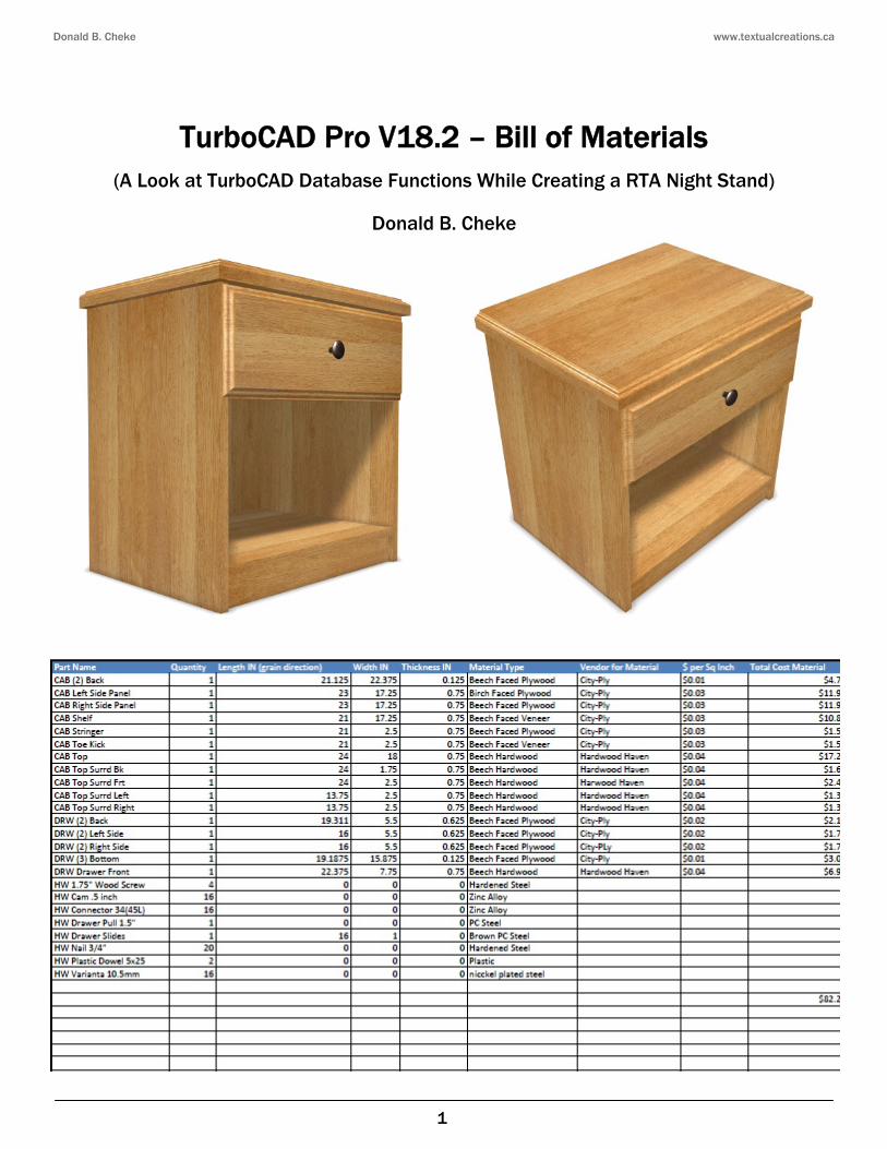
TurboCAD Pro V18.2 – Bill of Materials
(A Look at TurboCAD Database Functions While Creating a RTA Night Stand)
Donald B. Cheke
Donald B. Cheke www.textualcreations.ca
2
Copyright © 2011 Donald B. Cheke TurboCAD is a registered trademark of IMSI/Design.
Published by: Donald B. Cheke Saskatoon, SK Canada Visit: www.textualcreations.ca
All rights reserved No part of this document may be reproduced, copied, stored on a retrieval system or transmitted in any form without written permission from the author. The purchaser may, however, print one copy of the document to paper and may make one backup copy of the downloaded material for personal safe keeping. Limitation of Liability While every effort has been taken in the preparation and the writing of this document the author assumes no responsibility for errors and/or omissions nor for the uses of the material and the decisions based on such use. No warranties are made, express or implied with regard to either the contents of the document, its merchant ability or fitness for a particular purpose. The author should not be liable for direct, indirect, special, incidental or consequential damages arising out of the use or inability to use the contents of this document. Special Note All of the work presented within this tutorial is based on TurboCAD Pro V18.2. Although users of previous versions are welcome to try the tutorial it cannot be stated what results will be achieved. Many changes, some subtle and others not so subtle, are made with each program revision. Although many steps and directions would be generic some may not be. The same can be said for tools between versions. Older versions may not have the same tools as Pro V18.2 and if the same tools are available the tools themselves may have been revised and hence, work in a different manner than they previously did.
Donald B. Cheke www.textualcreations.ca
3
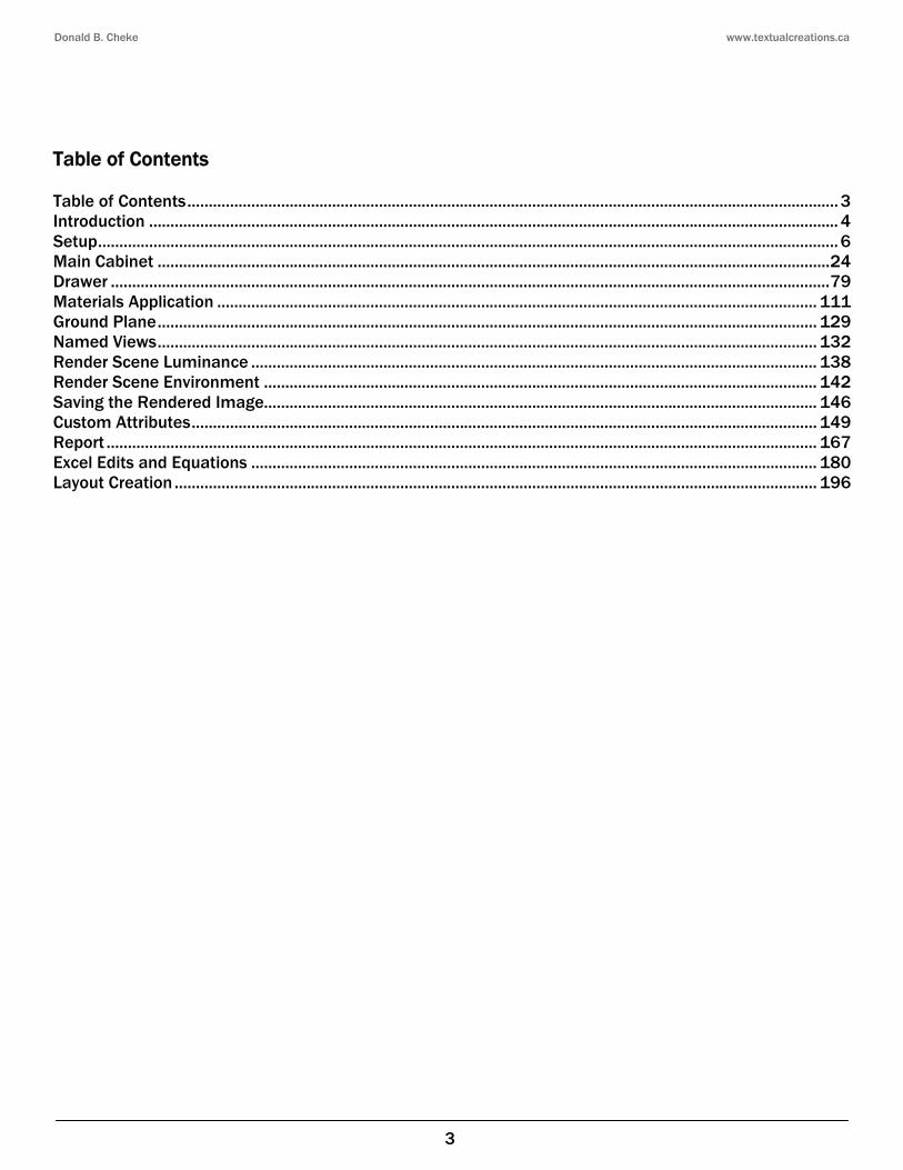
Table of Contents Table of Contents ......................................................................................................................................................... 3 Introduction .................................................................................................................................................................. 4 Setup .............................................................................................................................................................................. 6 Main Cabinet .............................................................................................................................................................. 24 Drawer ......................................................................................................................................................................... 79 Materials Application ............................................................................................................................................. 111 Ground Plane ........................................................................................................................................................... 129 Named Views ........................................................................................................................................................... 132 Render Scene Luminance ..................................................................................................................................... 138 Render Scene Environment .................................................................................................................................. 142 Saving the Rendered Image.................................................................................................................................. 146 Custom Attributes ................................................................................................................................................... 149 Report ....................................................................................................................................................................... 167 Excel Edits and Equations ..................................................................................................................................... 180 Layout Creation ....................................................................................................................................................... 196
Donald B. Cheke www.textualcreations.ca
4
Introduction An important part of any design scheme is the ability to create a list of parts and materials used within a drawing. Although TurboCAD does not have a dedicated bill of materials function per se it does come with some tools that can be used to create a report that can be used in the production of a bill of materials. All of the initial work is done right in TurboCAD and through the onboard export functions some additional automation can be added using Microsoft Excel or other such spreadsheet software. Within the tutorial the reader will be led through each keystroke to produce all components of the night stand that is illustrated on the cover of the tutorial, with the exception of the hardware which has been supplied. Aside from learning how to draw in TurboCAD, the user will learn how to set up the drawing and how to insert standard lighting. The reader will learn how to establish render scene luminance and a render scene environment. The reader will also learn how to render their drawing and save it in a high resolution image format. The reader will also learn what steps to take to give custom attributes to all the parts of the night stand and how to create a detailed report for use in a final Excel bill of materials. The user will also learn how to use the layout tool to create a cutting plan, a plan that could be exported and perhaps used in conjunction with one's cnc machine. As a commercial cabinet maker the author always worked in metric and utilized the European System 32. In determining what measures to use while creating this tutorial the author considered one thing over all others - that of calculating material costs. It was decided that Imperial (inches) would be used because the calculations for cost ($ per square inch seemed more reasonable that $ per square millimeter). This tutorial is in no way intended to teach the fundamentals of furniture design or construction but rather it is intended to teach the use of some of the tools that TurboCAD has to offer and to introduce the new user to a drawing methodology. The author feels confident that the techniques outlined within the tutorial can help lay the foundation for future successful TurboCAD drawing and illustration for even the newest user. As with any technically advanced software, the user is generally faced with a steep learning curve. It is the hope of the author that the money and time spent working through a Textual Creations tutorial will help ease the learning and allow the reader to come away feeling confident that they made a wise decision. This tutorial will assume that the reader has the Platinum Edition of TurboCAD Pro 18.2 with its extra architectural and mechanical tools, although no architectural or mechanical specific tools are used that the author is aware of. There are many ways to approach a project and it is likely that each person using the program would proceed in very different ways, so be open to alternative methods as experience builds. What is important is that the user becomes familiar with the objects that they wish to model and begin to look at them in a different way than they might otherwise do. What primitive shapes make up the whole? What will be required of these primitive shapes early in the drawing and how will this affect needs further along? What component or components should be started with? Many questions can only be answered through experience, but hopefully some of them will be answered by the time the beginner has worked through this tutorial. There is a great deal covered in this tutorial and the author urges the beginner to be patient, to read very carefully and to take the time necessary to do a good job. Try to enjoy the process as much as you will enjoy the final results. This tutorial assumes that the beginner has studied the desktop to some degree and can locate most of the tools. Since there are endless desktop configurations that can be set up in TurboCAD the author has
Donald B. Cheke www.textualcreations.ca
5
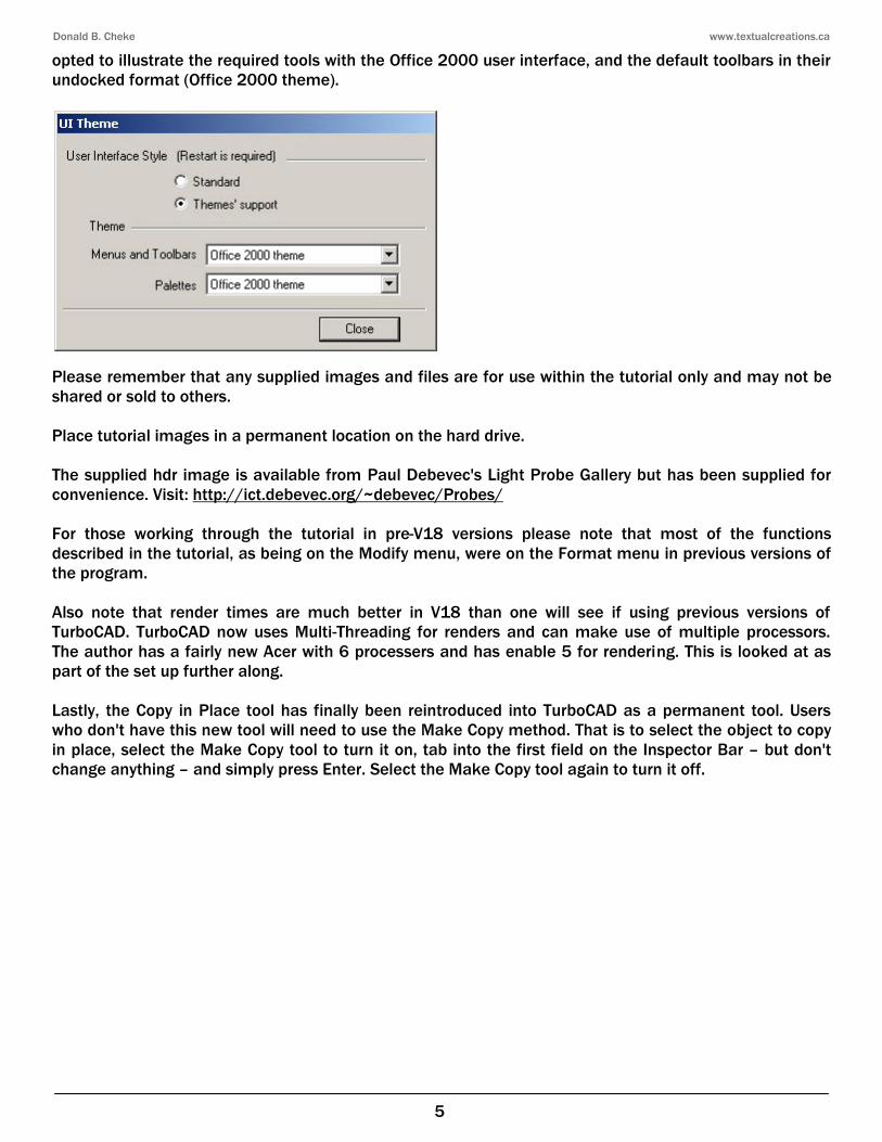
opted to illustrate the required tools with the Office 2000 user interface, and the default toolbars in their undocked format (Office 2000 theme).
Please remember that any supplied images and files are for use within the tutorial only and may not be shared or sold to others. Place tutorial images in a permanent location on the hard drive. The supplied hdr image is available from Paul Debevec's Light Probe Gallery but has been supplied for convenience. Visit: http://ict.debevec.org/~debevec/Probes/ For those working through the tutorial in pre-V18 versions please note that most of the functions described in the tutorial, as being on the Modify menu, were on the Format menu in previous versions of the program. Also note that render times are much better in V18 than one will see if using previous versions of TurboCAD. TurboCAD now uses Multi-Threading for renders and can make use of multiple processors. The author has a fairly new Acer with 6 processers and has enable 5 for rendering. This is looked at as part of the set up further along. Lastly, the Copy in Place tool has finally been reintroduced into TurboCAD as a permanent tool. Users who don't have this new tool will need to use the Make Copy method. That is to select the object to copy in place, select the Make Copy tool to turn it on, tab into the first field on the Inspector Bar – but don't change anything – and simply press Enter. Select the Make Copy tool again to turn it off.
Donald B. Cheke www.textualcreations.ca
29
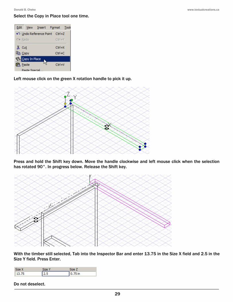
Select the Copy in Place tool one time.
Left mouse click on the green X rotation handle to pick it up.
Press and hold the Shift key down. Move the handle clockwise and left mouse click when the selection has rotated 90°. In progress below. Release the Shift key.
With the timber still selected, Tab into the Inspector Bar and enter 13.75 in the Size X field and 2.5 in the Size Y field. Press Enter.
Do not deselect.
Donald B. Cheke www.textualcreations.ca
30
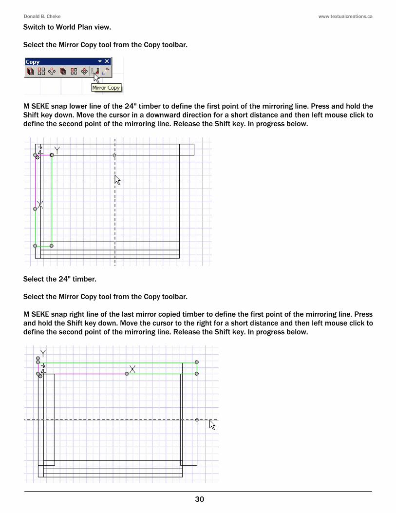
Switch to World Plan view. Select the Mirror Copy tool from the Copy toolbar.
M SEKE snap lower line of the 24" timber to define the first point of the mirroring line. Press and hold the Shift key down. Move the cursor in a downward direction for a short distance and then left mouse click to define the second point of the mirroring line. Release the Shift key. In progress below.
Select the 24" timber. Select the Mirror Copy tool from the Copy toolbar. M SEKE snap right line of the last mirror copied timber to define the first point of the mirroring line. Press and hold the Shift key down. Move the cursor to the right for a short distance and then left mouse click to define the second point of the mirroring line. Release the Shift key. In progress below.
Donald B. Cheke www.textualcreations.ca
51
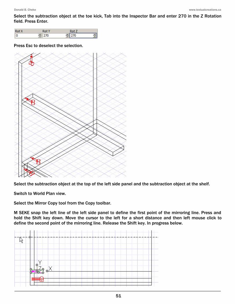
Select the subtraction object at the toe kick, Tab into the Inspector Bar and enter 270 in the Z Rotation field. Press Enter.
Press Esc to deselect the selection.
Select the subtraction object at the top of the left side panel and the subtraction object at the shelf. Switch to World Plan view. Select the Mirror Copy tool from the Copy toolbar. M SEKE snap the left line of the left side panel to define the first point of the mirroring line. Press and hold the Shift key down. Move the cursor to the left for a short distance and then left mouse click to define the second point of the mirroring line. Release the Shift key. In progress below.
Donald B. Cheke www.textualcreations.ca
52
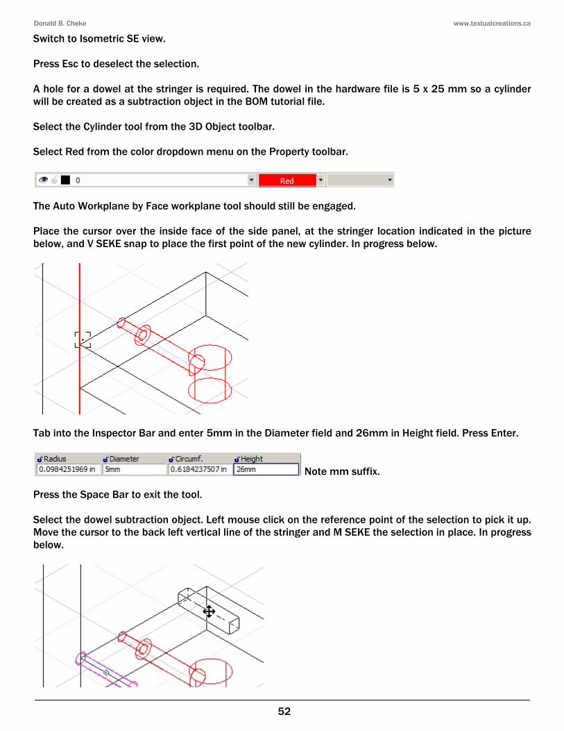
Switch to Isometric SE view. Press Esc to deselect the selection. A hole for a dowel at the stringer is required. The dowel in the hardware file is 5 x 25 mm so a cylinder will be created as a subtraction object in the BOM tutorial file. Select the Cylinder tool from the 3D Object toolbar. Select Red from the color dropdown menu on the Property toolbar.
The Auto Workplane by Face workplane tool should still be engaged. Place the cursor over the inside face of the side panel, at the stringer location indicated in the picture below, and V SEKE snap to place the first point of the new cylinder. In progress below.
Tab into the Inspector Bar and enter 5mm in the Diameter field and 26mm in Height field. Press Enter.
Note mm suffix. Press the Space Bar to exit the tool. Select the dowel subtraction object. Left mouse click on the reference point of the selection to pick it up. Move the cursor to the back left vertical line of the stringer and M SEKE the selection in place. In progress below.
Donald B. Cheke www.textualcreations.ca
88
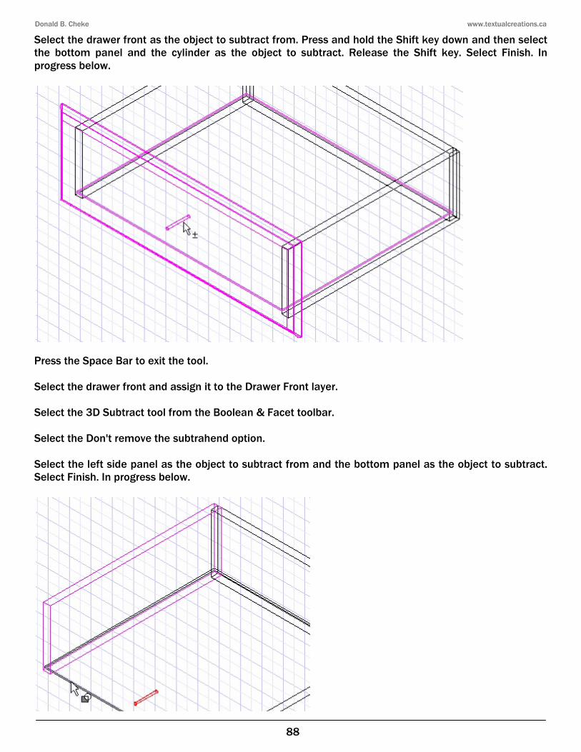
Select the drawer front as the object to subtract from. Press and hold the Shift key down and then select the bottom panel and the cylinder as the object to subtract. Release the Shift key. Select Finish. In progress below.
Press the Space Bar to exit the tool. Select the drawer front and assign it to the Drawer Front layer. Select the 3D Subtract tool from the Boolean & Facet toolbar. Select the Don't remove the subtrahend option. Select the left side panel as the object to subtract from and the bottom panel as the object to subtract. Select Finish. In progress below.
Donald B. Cheke www.textualcreations.ca
109
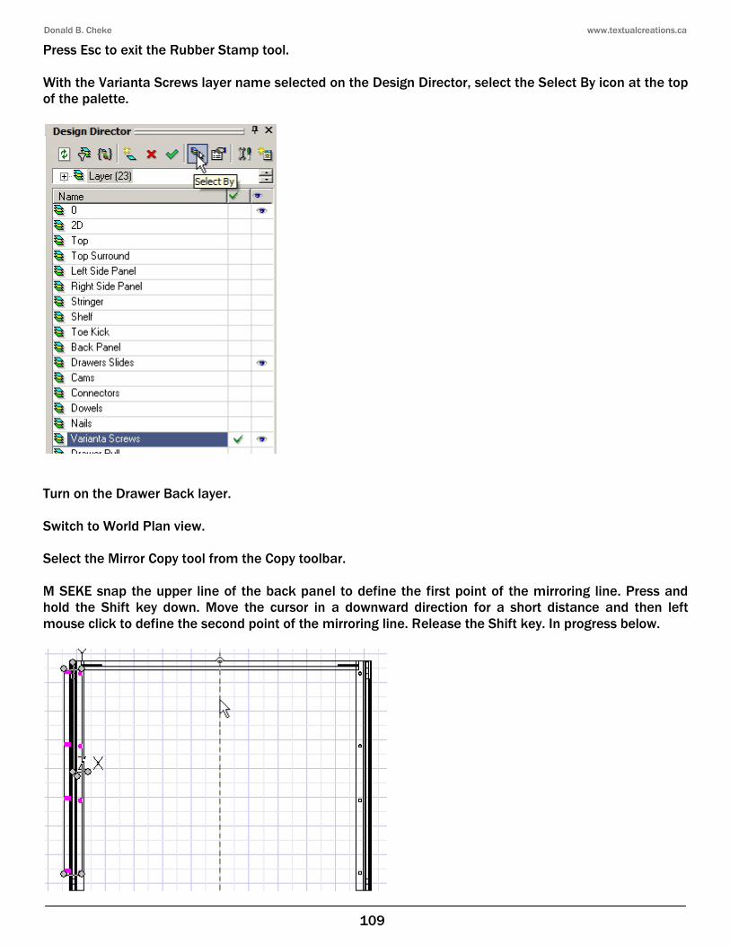
Press Esc to exit the Rubber Stamp tool. With the Varianta Screws layer name selected on the Design Director, select the Select By icon at the top of the palette.
Turn on the Drawer Back layer. Switch to World Plan view. Select the Mirror Copy tool from the Copy toolbar. M SEKE snap the upper line of the back panel to define the first point of the mirroring line. Press and hold the Shift key down. Move the cursor in a downward direction for a short distance and then left mouse click to define the second point of the mirroring line. Release the Shift key. In progress below.
Donald B. Cheke www.textualcreations.ca
110
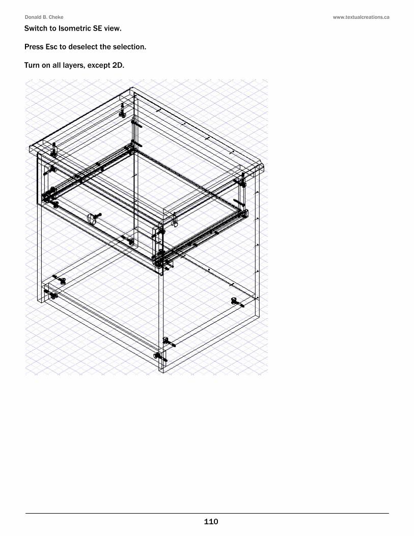
Switch to Isometric SE view. Press Esc to deselect the selection. Turn on all layers, except 2D.
Donald B. Cheke www.textualcreations.ca
136
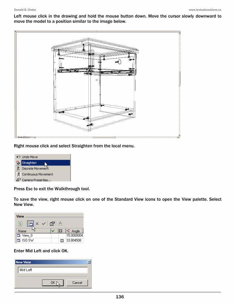
Left mouse click in the drawing and hold the mouse button down. Move the cursor slowly downward to move the model to a position similar to the image below.
Right mouse click and select Straighten from the local menu.
Press Esc to exit the Walkthrough tool. To save the view, right mouse click on one of the Standard View icons to open the View palette. Select New View.
Enter Mid Left and click OK.

Donald B. Cheke www.textualcreations.ca
137
Close the View palette. Turn on the Ground Plane layer. Select the Quality Rendering icon on the Render toolbar and allow time for the screen to render (10 seconds on the author's off the shelf Acer).
Donald B. Cheke www.textualcreations.ca
153
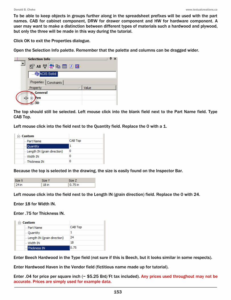
To be able to keep objects in groups further along in the spreadsheet prefixes will be used with the part names. CAB for cabinet component, DRW for drawer component and HW for hardware component. A user may want to make a distinction between different types of materials such a hardwood and plywood, but only the three will be made in this way during the tutorial. Click OK to exit the Properties dialogue. Open the Selection Info palette. Remember that the palette and columns can be dragged wider.
The top should still be selected. Left mouse click into the blank field next to the Part Name field. Type CAB Top. Left mouse click into the field next to the Quantity field. Replace the 0 with a 1.
Because the top is selected in the drawing, the size is easily found on the Inspector Bar.
Left mouse click into the field next to the Length IN (grain direction) field. Replace the 0 with 24. Enter 18 for Width IN. Enter .75 for Thickness IN.
Enter Beech Hardwood in the Type field (not sure if this is Beech, but it looks similar in some respects). Enter Hardwood Haven in the Vendor field (fictitious name made up for tutorial). Enter .04 for price per square inch (~ $5.25 Brd/Ft tax included). Any prices used throughout may not be accurate. Prices are simply used for example data.
Donald B. Cheke www.textualcreations.ca
175
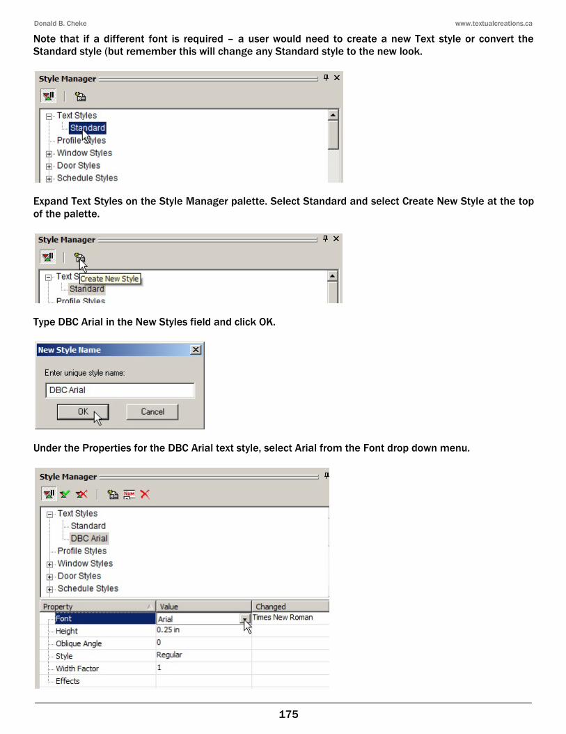
Note that if a different font is required – a user would need to create a new Text style or convert the Standard style (but remember this will change any Standard style to the new look.
Expand Text Styles on the Style Manager palette. Select Standard and select Create New Style at the top of the palette.
Type DBC Arial in the New Styles field and click OK.
Under the Properties for the DBC Arial text style, select Arial from the Font drop down menu.
Donald B. Cheke www.textualcreations.ca
189
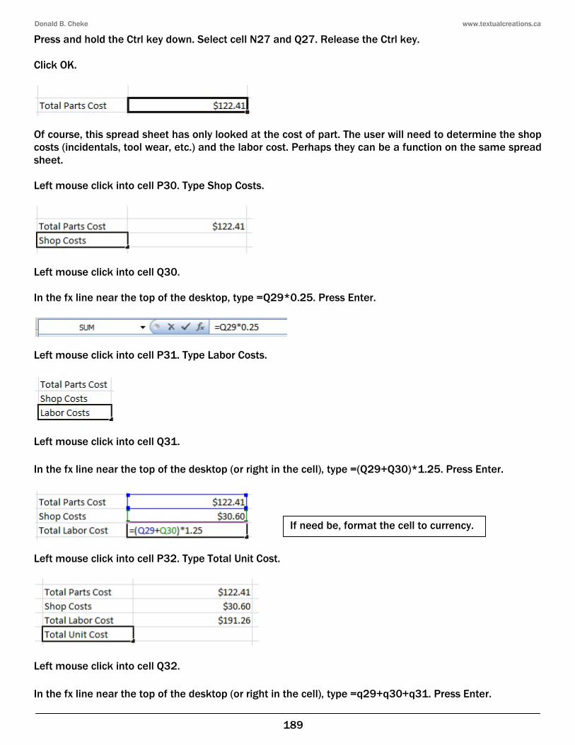
Press and hold the Ctrl key down. Select cell N27 and Q27. Release the Ctrl key. Click OK.
Of course, this spread sheet has only looked at the cost of part. The user will need to determine the shop costs (incidentals, tool wear, etc.) and the labor cost. Perhaps they can be a function on the same spread sheet. Left mouse click into cell P30. Type Shop Costs.
Left mouse click into cell Q30. In the fx line near the top of the desktop, type =Q29*0.25. Press Enter.
Left mouse click into cell P31. Type Labor Costs.
Left mouse click into cell Q31. In the fx line near the top of the desktop (or right in the cell), type =(Q29+Q30)*1.25. Press Enter.
Left mouse click into cell P32. Type Total Unit Cost.
Left mouse click into cell Q32. In the fx line near the top of the desktop (or right in the cell), type =q29+q30+q31. Press Enter.
If need be, format the cell to currency.
Donald B. Cheke www.textualcreations.ca
196
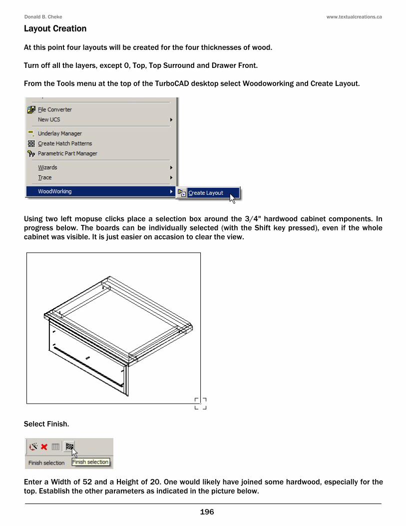
Layout Creation At this point four layouts will be created for the four thicknesses of wood. Turn off all the layers, except 0, Top, Top Surround and Drawer Front. From the Tools menu at the top of the TurboCAD desktop select Woodoworking and Create Layout.
Using two left mopuse clicks place a selection box around the 3/4" hardwood cabinet components. In progress below. The boards can be individually selected (with the Shift key pressed), even if the whole cabinet was visible. It is just easier on accasion to clear the view.
Select Finish.
Enter a Width of 52 and a Height of 20. One would likely have joined some hardwood, especially for the top. Establish the other parameters as indicated in the picture below.
Donald B. Cheke www.textualcreations.ca
210
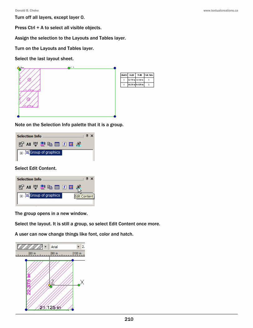
Turn off all layers, except layer 0. Press Ctrl + A to select all visible objects. Assign the selection to the Layouts and Tables layer. Turn on the Layouts and Tables layer. Select the last layout sheet.
Note on the Selection Info palette that it is a group.
Select Edit Content.
The group opens in a new window. Select the layout. It is still a group, so select Edit Content once more. A user can now change things like font, color and hatch.