Embed Size (px)
Citation preview

USER’S MANUAL
GA-8IEXWP4 Titan 533 Motherboard
Pentium®4 P rocessor MotherboardRev. 1001
12ME-8IEXW-1001
- 2-
Engl
ish
GA-8IEXW Motherboard
Table of Content
Item Checklist .................................................................................4WARNING! .......................................................................................4 Chapter 1 Introduction ......................................................................5
Features Summary................................................................................................ 5GA-8IEXW Motherboard Layout ......................................................................... 7
Chapter 2 Hardware Installation Process ...........................................8Step 1: Install the Central Processing Unit (CPU) ........................................... 9
Step 1-2:CPU Heat Sink Installation ............................................................... 10
Step 2: Install memory modules ....................................................................... 11Step 3: Install expansion cards ......................................................................... 13Step 4: Connect ribbon cables, cabinet wires, and power supply ............. 14
Step 4-1 : I/O Back Panel Introduction ........................................................... 14Step 4-2 :Connectors & Jumper Setting Introduction ......................................... 16
Chapter 3 BIOS Setup .................................................................... 24Q-Flash Utility ....................................................................................................... 25Main (For example: BIOS Ver. :F1) .................................................................. 26Advanced ............................................................................................................... 29
Adv anced BIOS Features ............................................................................ 29Integrated Peripherals ................................................................................ 32Pow er Management Setup .......................................................................... 35Pnp/PCI Configuration ................................................................................. 38
Boot ........................................................................................................................ 39Server ..................................................................................................................... 41Security .................................................................................................................. 45Clk/Voltage ............................................................................................................ 47Defaults .................................................................................................................. 48Exit .......................................................................................................................... 49

English
- 3-
Table of Content
Chapter 4 Technical Reference ........................................................ 50Block Diagram ..................................................................................................... 50
Chapter 5 Appendix ........................................................................ 51
- 4-
Engl
ish
GA-8IEXW Motherboard
Computer motherboards and expansion cards contain very delicate Integrated Circuit (IC) chips. Toprotect them against damage from static electric ity , y ou should follow some precautions wheneveryou work on your computer.
1. Unplug your computer w hen w orking on the inside.
2. Use a grounded w rist strap before handling computer components. If y ou do not hav eone, touch both of y our hands to a safely grounded object or to a metal object, such as the pow er supply case.
3. Hold components by the edges and try not touch the IC chips, leads or connectors, orother components.
4. Place components on a grounded antistatic pad or on the bag that came w ith thecomponents w henev er the components are separated from the sy stem.
5. Ensure that the ATX pow er supply is sw itched off before you plug in or remov e the ATX
pow er connector on the motherboard.
If the motherboard has mounting holes, but they don’t line up with the holes on the base andthere are no slots to attach the spacers, do not become alarmed y ou can still attach the spacers tothe mounting holes. Just cut the bottom portion of the spacers (the spacer may be a li ttle hard tocut off, so be careful of your hands). In this way y ou can stil l attach the motherboard to the basewithout worry ing about short circuits. Sometimes you may need to use the plastic springs to isolatethe screw from the motherboard PCB surface, because the circuit wire may be near by the hole. Becareful, don’t let the screw contact any printed c ircuit write or parts on the PC B that are near thefix ing hole, otherwise it may damage the board or cause board malfunctioning.
Installing the motherboard to the chassis…
WARNING!
þ The GA-8IEXW motherboardþ IDE (ATA100 ) cable x 1 / Floppy cable x 1þ IDE (ATA133 )cable x 2þ CD for motherboard driver & utilityþ GA-8IEXW user’s manualþ I/O Shield
Item Checklist
- 5-
Introduction
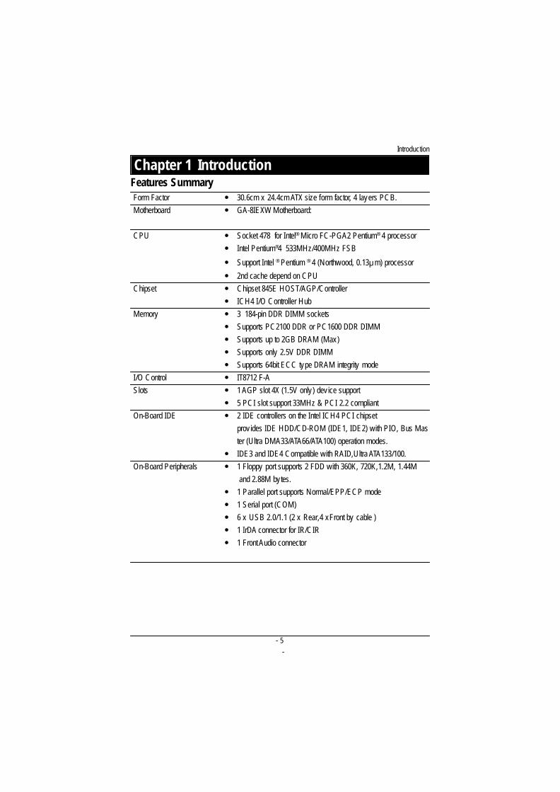
Chapter 1 IntroductionFeatures SummaryForm Factor � 30.6cm x 24.4cm ATX size form factor, 4 layers PCB.Motherboard � GA-8IEXW Motherboard:
CPU � Socket 478 for Intel® Micro FC-PGA2 Pentium® 4 processor� Intel Pentium®4 533MHz/400MHz FSB
� Support Intel ® Pentium ® 4 (Northwood, 0.13 m) processor
� 2nd cache depend on CPUChipset � Chipset 845E HOST/AGP/Controller
� ICH4 I/O Controller HubMemory � 3 184-pin DDR DIMM sockets
� Supports PC2100 DDR or PC1600 DDR DIMM� Supports up to 2GB DRAM (Max)� Supports only 2.5V DDR DIMM� Supports 64bit ECC type DRAM integrity mode
I/O Control � IT8712 F-ASlots � 1 AGP slot 4X (1.5V only) dev ice support
� 5 PCI slot support 33MHz & PCI 2.2 compliantOn-Board IDE � 2 IDE controllers on the Intel ICH4 PCI chipset
prov ides IDE HDD/CD-ROM (IDE1, IDE2) with PIO, Bus Master (Ultra DMA33/ATA66/ATA100) operation modes.
� IDE3 and IDE4 Compatible with RAID,Ultra ATA133/100.On-Board Peripherals � 1 Floppy port supports 2 FDD with 360K, 720K,1.2M, 1.44M
and 2.88M bytes.� 1 Parallel port supports Normal/EPP/ECP mode� 1 Serial port (COM)� 6 x USB 2.0/1.1 (2 x Rear,4 xFront by cable )� 1 IrDA connector for IR/CIR� 1 Front Audio connector
- 6-
Engl
ish
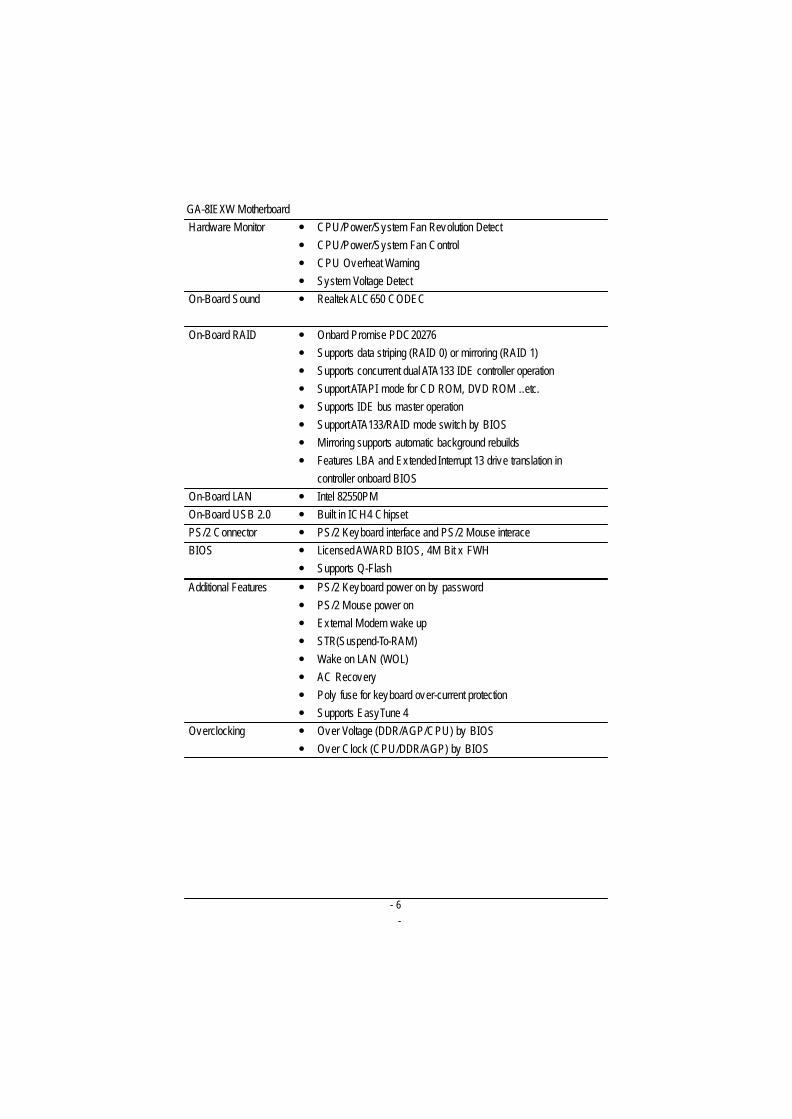
GA-8IEXW MotherboardHardware Monitor � CPU/Power/System Fan Revolution Detect
� CPU/Power/System Fan Control� CPU Overheat Warning� System Voltage Detect
On-Board Sound � Realtek ALC650 CODEC
On-Board RAID � Onbard Promise PDC20276� Supports data striping (RAID 0) or mirroring (RAID 1)� Supports concurrent dual ATA133 IDE controller operation� Support ATAPI mode for CD ROM, DVD ROM ..etc.� Supports IDE bus master operation� Support ATA133/RAID mode switch by BIOS� Mirroring supports automatic background rebuilds� Features LBA and Extended Interrupt 13 drive translation in
controller onboard BIOSOn-Board LAN � Intel 82550PMOn-Board USB 2.0 � Built in ICH4 ChipsetPS/2 Connector � PS/2 Keyboard interface and PS/2 Mouse interaceBIOS � Licensed AWARD BIOS, 4M Bit x FWH
� Supports Q-Flash
Additional Features � PS/2 Keyboard power on by password� PS/2 Mouse power on� External Modem wake up� STR(Suspend-To-RAM)� Wake on LAN (WOL)� AC Recovery� Poly fuse for keyboard over-current protection� Supports EasyTune 4
Overclocking � Over Voltage (DDR/AGP/CPU) by BIOS� Over Clock (CPU/DDR/AGP) by BIOS
- 7-
Hardware Installation Process
SOCKET478
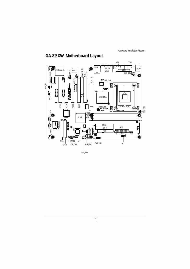
GA-8IEXW Motherboard Layout
SOCKET478
Intel 845E
ICH4
AC97
BATT
ERY
FDD
IDE 2IDE 1
NB_FAN
ATI Rage XL
W98
6432
DH
-6
VGA_
EN
WO
R
USB
LAN
MIC_IN LINE_OUTLINE_INGAME
VGA COM
LPT1KB_MS
ATX
PDC
2027
6
F_U
SB2/
4F_
USB
1/3
IDE 3
IDE 4
SYS_FAN
PWR_FANCI
CLR_CMOSCP
U_FA
N
AUX_12VCD
_IN
AUX_
IN
PCI 5
PCI 4
PCI 3
PCI 2
PCI 1
AGP
Slot
SPDI
F
IR
BIO
S
DDR1DDR 2DDR 3
Model_SW1
CPU
F_PANEL
- 8-
Engl
ish
GA-8IEXW Motherboard
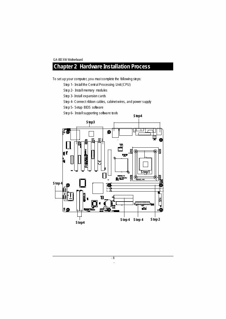
To set up your computer, you must complete the following steps:
Step 1- Install the Central Processing Unit (CPU)
Step 2- Install memory modules
Step 3- Install expansion cards
Step 4- Connect ribbon cables, cabinet w ires, and power supply
Step 5- Setup BIOS software
Step 6- Install supporting software tools
Chapter 2 Hardware Installation Process
Step 4 Step 4 Step 2
Step1
Step3
Step 4
Step4
Step4
- 9-
Hardware Installation Process
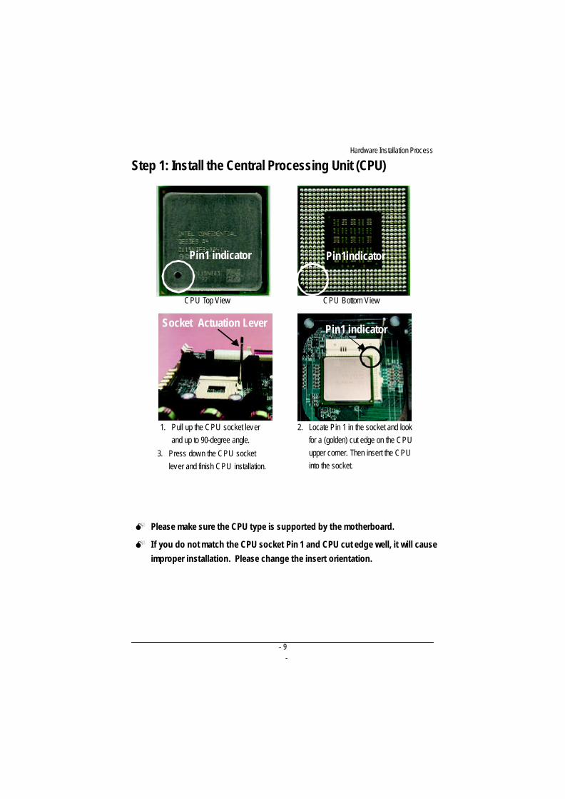
Step 1: Install the Central Processing Unit (CPU)
Pin1 indicator Pin1indicator
CPU Top View CPU Bottom View
Socket Actuation Lever
1. Pull up the CPU socket leverand up to 90-degree angle.
Pin1 indicator
2. Locate Pin 1 in the socket and lookfor a (golden) cut edge on the CPUupper corner. Then insert the CPUinto the socket.
3. Press down the CPU socketlever and finish CPU installation.
M Please make sure the CPU type is supported by the motherboard.
M I f you do not match the CPU socket Pin 1 and CPU cut edge well, it will cause
improper installation. Please change the insert orientation.
- 10-
Engl
ish
GA-8IEXW Motherboard
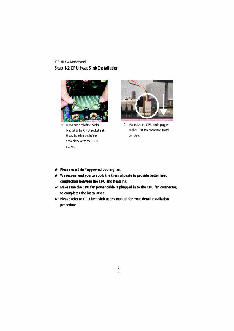
Step 1-2:CPU Heat Sink Installation
1. Hook one end of the coolerbracket to the CPU socket first.Hook the other end of thecooler bracket to the CPUsocket.
2. Make sure the CPU fan is plugged to the CPU fan connector. Installcomplete.
M Please use Intel® approved cooling fan.
M We recommend you to apply the thermal paste to provide better heat
conduction between the CPU and heatsink.
M Make sure the CPU fan power cable is plugged in to the CPU fan connector,
to completes the installation.
M Please refer to CPU heat sink user’s manual for more detail installation
procedure.
- 11-
Hardware Installation Process
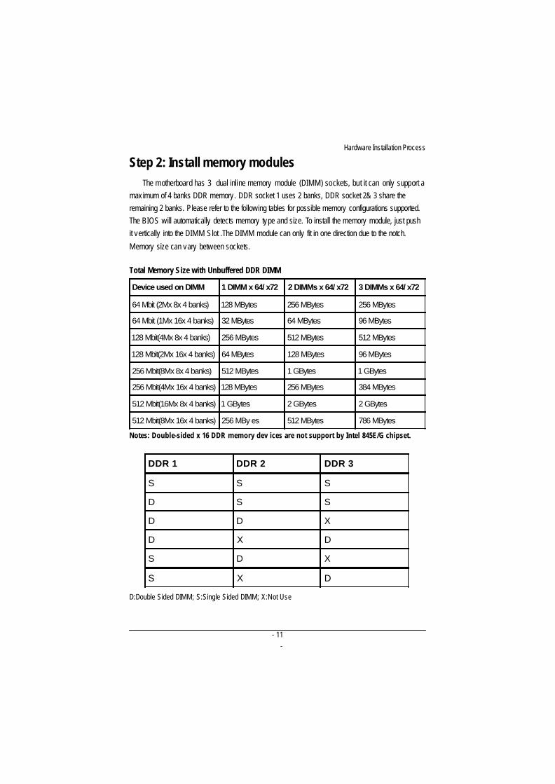
Step 2: Install memory modulesThe motherboard has 3 dual inline memory module (DIMM) sockets, but it can only support a
maximum of 4 banks DDR memory. DDR socket 1 uses 2 banks, DDR socket 2& 3 share theremaining 2 banks. Please refer to the following tables for possible memory configurations supported.The BIOS will automatically detects memory type and size. To install the memory module, just pushit vertically into the DIMM Slot .The DIMM module can only fit in one direction due to the notch.
Memory size can vary between sockets.
Total Memory Size with Unbuffered DDR DIMM
Device used on DIMM 1 DIMM x 64/ x72 2 DIMMs x 64/ x72 3 DIMMs x 64/ x72
64 Mbit (2Mx 8x 4 banks) 128 MBytes 256 MBytes 256 MBytes
64 Mbit (1Mx 16x 4 banks) 32 MBytes 64 MBytes 96 MBytes
128 Mbit(4Mx 8x 4 banks) 256 MBytes 512 MBytes 512 MBytes
128 Mbit(2Mx 16x 4 banks) 64 MBytes 128 MBytes 96 MBytes
256 Mbit(8Mx 8x 4 banks) 512 MBytes 1 GBytes 1 GBytes
256 Mbit(4Mx 16x 4 banks) 128 MBytes 256 MBytes 384 MBytes
512 Mbit(16Mx 8x 4 banks) 1 GBytes 2 GBytes 2 GBytes
512 Mbit(8Mx 16x 4 banks) 256 MBy es 512 MBytes 786 MBytes
Notes: Double-sided x 16 DDR memory dev ices are not support by Intel 845E/G chipset.
DDR 1 DDR 2 DDR 3
S S S
D S S
D D X
D X D
S D X
S X D
D:Double Sided DIMM; S:Single Sided DIMM; X:Not Use
- 12-
Engl
ish
GA-8IEXW Motherboard
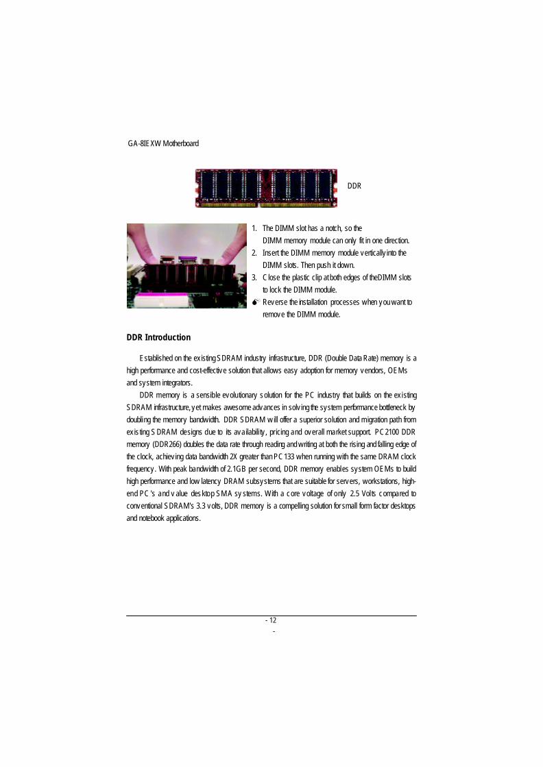
DDR Introduction
Established on the ex isting SDRAM industry infrastructure, DDR (Double Data Rate) memory is ahigh performance and cost-effective solution that allows easy adoption for memory vendors, OEMsand system integrators.
DDR memory is a sensible evolutionary solution for the PC industry that builds on the ex istingSDRAM infrastructure, yet makes awesome advances in solv ing the system performance bottleneck bydoubling the memory bandwidth. DDR SDRAM w ill offer a superior solution and migration path fromexis ting S DRAM designs due to its availabili ty , pricing and overall market support. PC2100 DDRmemory (DDR266) doubles the data rate through reading and writing at both the rising and falling edge ofthe clock, achiev ing data bandwidth 2X greater than PC133 when running with the same DRAM clockfrequency. With peak bandwidth of 2.1GB per second, DDR memory enables system OEMs to buildhigh performance and low latency DRAM subsystems that are suitable for servers, workstations, high-end PC 's and v alue desktop SM A sy stems. With a core voltage of only 2.5 Volts compared toconventional SDRAM's 3.3 volts, DDR memory is a compelling solution for small form factor desktopsand notebook applications.
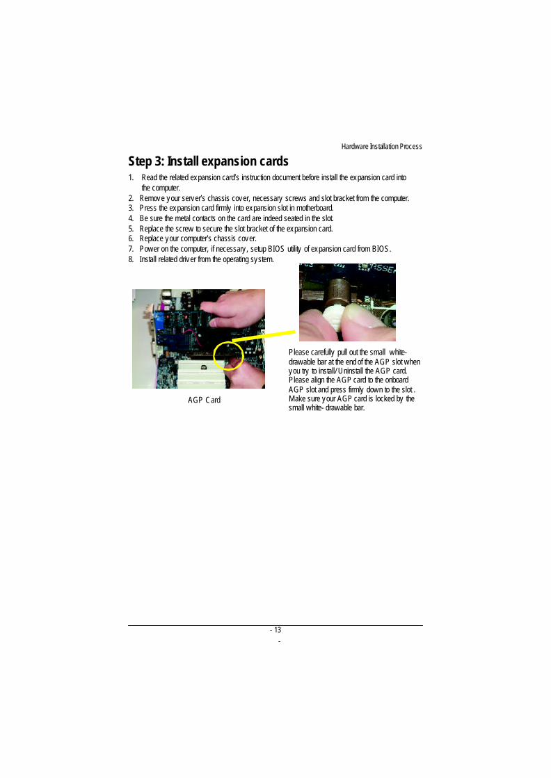
1. The DIMM slot has a notch, so theDIMM memory module can only fit in one direction.
2. Insert the DIMM memory module vertically into theDIMM slots. Then push it down.
3. Close the plastic clip at both edges of theDIMM slotsto lock the DIMM module.
M Reverse the installation processes when you want toremove the DIMM module.
DDR
- 13-
Hardware Installation Process
Step 3: Install expansion cards1. Read the related expansion card’s instruction document before install the expansion card into
the computer.2. Remove your server’s chassis cover, necessary screws and slot bracket from the computer.3. Press the expansion card firmly into expansion slot in motherboard.4. Be sure the metal contacts on the card are indeed seated in the slot.5. Replace the screw to secure the slot bracket of the expansion card.6. Replace your computer’s chassis cover.7. Power on the computer, if necessary, setup BIOS utility of expansion card from BIOS.8. Install related driver from the operating system.
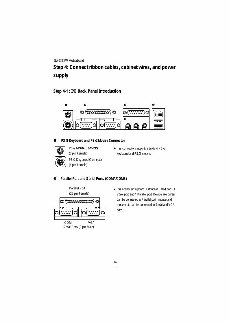
AGP Card
Please carefully pull out the small white-drawable bar at the end of the AGP slot whenyou try to install/ Uninstall the AGP card.Please align the AGP card to the onboardAGP slot and press firmly down to the slot .Make sure your AGP card is locked by thesmall white- drawable bar.
- 14-
Engl
ish
GA-8IEXW Motherboard
Step 4: Connect ribbon cables, cabinet wires, and powersupply
Step 4-1 : I/O Back Panel Introduction
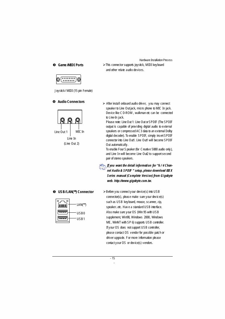
u PS/2 Keyboard and PS/2 Mouse Connector
PS/2 Mouse Connector(6 pin Female)
PS/2 K eyboard Connector(6 pin Female)
ØThis connector supports s tandard P S/2keyboard and PS/2 mouse.
u v w
x
y
v Parallel Port and Serial Ports (COMA/COMB)
ØThis connector supports 1 standard COM port , 1 VGA port and 1 Parallel port. Device like printer can be connected to Parallel port ; mouse and modem etc can be connected to Serial and VGA ports.
Parallel Port(25 pin Female)
COM VGASerial Ports (9 pin Male)
- 15-
Hardware Installation Process
w Game /MIDI Ports
Joystick / MIDI (15 pin Female)
x Audio Connectors
ØThis connector supports joystick, M IDI keyboardand other relate audio dev ices.
Ø After install onboard audio driver, you may connectspeaker to Line Out jack, micro phone to MIC In jack.Device like C D-ROM , walkman etc can be connectedto Line-In jack.Please note: Line Out 1: Line Out or SPDIF (The SPDIFoutput is capable of prov iding digital audio to externalspeakers or compressed AC3 data to an external Dolbydigital decoder). To enable SPDIF, simply insert SPDIFconnector into Line Out1. Line Out1 will become SPDIFOut automatically .To enable Four S peaker (for Creative 5880 audio only),and Line In will become Line Out2 to support secondpair of stereo speakers.
If you want the detail information for “6 / 4 Chan-nel Audio & SPDIF “ setup, please download 8IEXSeries manual (Complete Version) from Gigabyteweb. http://www.gigabyte.com.tw.
y USB/ LAN(**) Connector ØBefore you connect your dev ice(s) into USBconnector(s), please make sure your dev ice(s)such as USB keyboard, mouse, scanner, zip,speaker..etc. Hav e a standard USB interface.Also make sure your OS (Win 95 with USBsupplement, Win98, Windows 2000, WindowsME, WinNT with SP 6) supports USB controller.If your OS does not support USB controller,please contact OS vendor for possible patch ordriver upgrade. For more information pleasecontact your OS or dev ice(s) vendors.
USB 0
USB 1
LAN(**)
Line In(Line Out 2)
MIC InLine Out 1
- 16-
Engl
ish
GA-8IEXW Motherboard
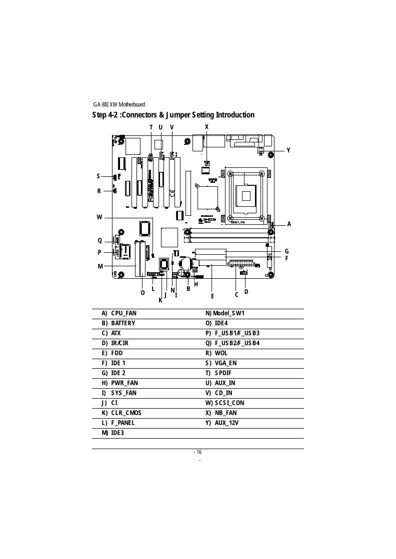
Step 4-2 :Connectors & Jumper Setting IntroductionT VU
W
X
Y
A) CPU_FAN N) Model_SW1
B) BATTERY O) IDE4
C) ATX P) F_USB1/F_USB3
D) IR/CIR Q) F_USB2/F_USB4
E) FDD R) WOL
F) IDE 1 S) VGA_EN
G) IDE 2 T) SPDIF
H) PWR_FAN U) AUX_IN
I) SYS_FAN V) CD_IN
J) CI W) SCSI_CON
K) CLR_CMOS X) NB_FAN
L) F_PANEL Y) AUX_12V
M) IDE3
I
HB
C DE
FG
A
JK
LO
M
Q
P
R
S
N
- 17-
Hardware Installation Process
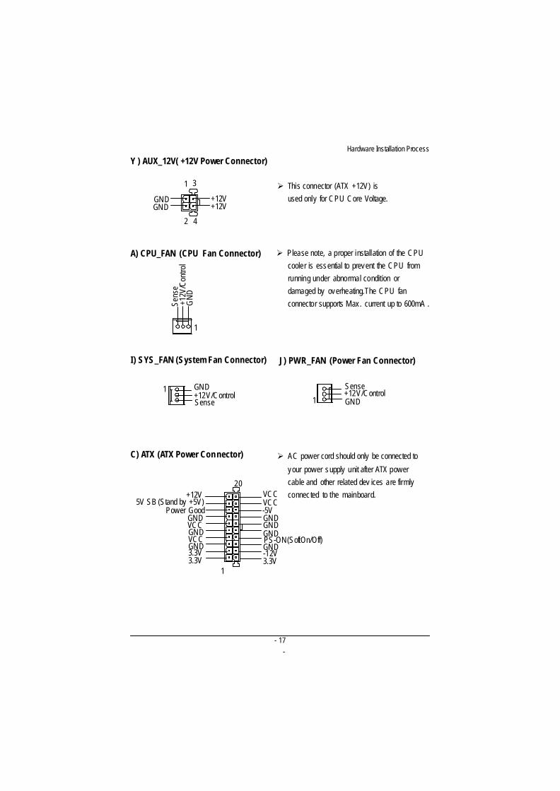
A) CPU_FAN (CPU Fan Connector)
C) ATX (ATX Power Con nector)
Ø Please note, a proper installation of the CPUcooler is essential to prevent the CPU fromrunning under abnormal condition ordamaged by overheating.The CPU fanconnector supports Max. current up to 600mA .
Ø This connector (ATX +12V) isused only for CPU Core Voltage.
Y ) AUX_12V( +12V Power Connector)
Ø AC power cord should only be connected to
your power supply unit after ATX powercable and other related dev ices are firmlyconnected to the mainboard.
I ) SYS_FAN (System Fan Connector)
1+12V/ControlSense
GND
1
+12V
/Con
trol
Sens
e
GN
D1
2
3
4
+12VGND+12VGND
PS-ON(Soft On/Off)
3.3V3.3VGND
GND
GND
VCC
VCC
+12V5V SB (Stand by +5V)
Power Good
3.3V
GND
GND
GNDGND
VCCVCC
-12V
1
20
-5V
J) PWR_FAN (Power Fan Connector)
+12V/ControlSense
GND1
- 18-
Engl
ish
GA-8IEXW Motherboard
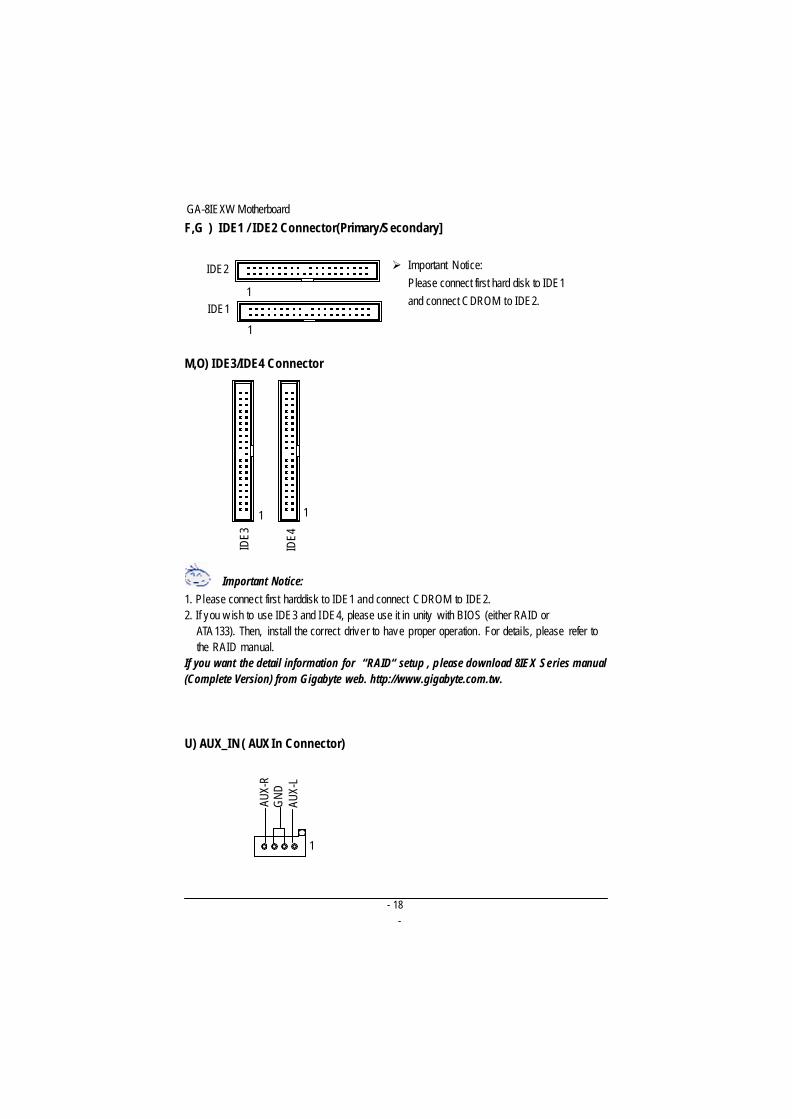
U) AUX_IN ( AUX In Connector)
F,G ) IDE1 / IDE2 Connector(Primary/Secondary]
M,O) IDE3/IDE4 Connector
Ø Important Notice:Please connect first hard disk to IDE1and connect CDROM to IDE2.
IDE4
1
1
AUX-
R
AUX-
LG
ND
Important Notice:1. Please connect first harddisk to IDE1 and connect CDROM to IDE2.2. If you w ish to use IDE3 and IDE4, please use it in unity with BIOS (either RAID or
ATA 133). Then, install the correct driver to have proper operation. For details, please refer tothe RAID manual.
If you want the detail information for “RAID“ setup , please download 8IEX Series manual(Complete Version) from Gigabyte web. http://www.gigabyte.com.tw.
1
IDE3
IDE2
1
1
IDE1
- 19-
Hardware Installation Process
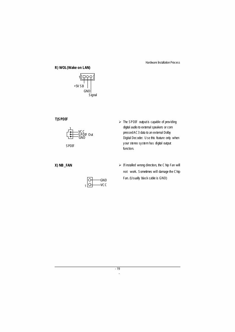
R) WOL(Wake on LAN)
1
+5V SBGND
Signal
T)SPDIFØ The SPDIF output is capable of prov iding
digital audio to external speakers or com pressed AC3 data to an external Dolby
Digital Decoder. U se this feature only whenyour stereo system has digital outputfunction.
SPDIF
VCCSPDIF OutGND
1
X) NB_FAN
1
Ø If installed wrong direction, the C hip Fan will
not work. Sometimes will damage the Chip
Fan. (Usually black cable is GND)
VCCGND
- 20-
Engl
ish
GA-8IEXW Motherboard
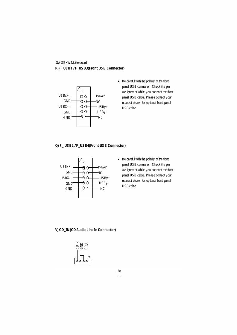
P)F_ USB1 / F_USB3(Front USB Connector)
Q) F_ USB2 / F_USB4(Front USB Connector)
V) CD_IN (CD Audio Line In Connector)
Ø Be careful with the polarity of the frontpanel USB connector. Check the pinass ignment while you connect the frontpanel USB cable. P lease contact yournearest dealer for optional front panelUSB cable.
Ø Be careful with the polarity of the frontpanel USB connector. Check the pinass ignment while you connect the frontpanel USB cable. P lease contact yournearest dealer for optional front panelUSB cable.
1
CD_R
CD_L
GN
D
1Power
GND
NCUSBy+
GND
GND
NC
USBx+
USBy-USBX-
1Power
GND
NCUSBy+
GND
GND
NC
USBx+
USBy-USBX-
- 21-
Hardware Installation Process
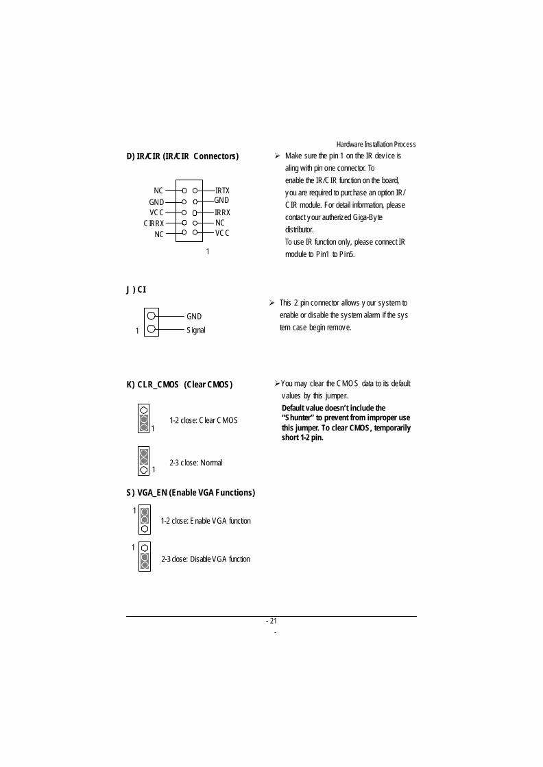
D) IR/CIR (IR/CIR Connectors) Ø Make sure the pin 1 on the IR dev ice isaling with pin one connector. Toenable the IR/CIR function on the board,you are required to purchase an option IR/CIR module. For detail information, pleasecontact your autherized Giga-Bytedistributor.To use IR function only, please connect IRmodule to Pin1 to Pin5.
VCCNCIRRXGNDIRTX
NC
VCCGND
NC
CIRRX
1
J ) CIØ This 2 pin connector allows y our system to
enable or disable the system alarm if the system case begin remove.
K) CLR_CMOS (Clear CMOS) ØYou may clear the CMOS data to its defaultvalues by this jumper.Default value doesn’t include the“Shunter” to prevent from improper usethis jumper. To clear CMOS, temporarilyshort 1-2 pin.
1 Signal
GND
S) VGA_EN (Enable VGA Functions)
1-2 close: Clear CMOS1
2-3 c lose: Normal1
1-2 close: Enable VGA function
2-3 close: Disable VGA function1
1
- 22-
Engl
ish
GA-8IEXW Motherboard
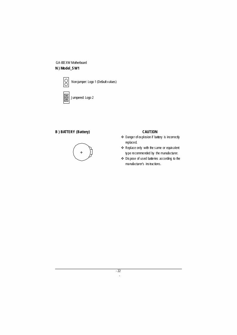
N ) Model_SW1
B ) BATTERY (Battery)
+
CAUTIONv Danger of explosion if battery is incorrectly
replaced.v Replace only with the same or equivalent
type recommended by the manufacturer.v Dispose of used batteries according to the
manufacturer’s instructions.
Non-jumper: Logo 1 (Default values)
Jumpered: Logo 2
- 23-
Hardware Installation Process
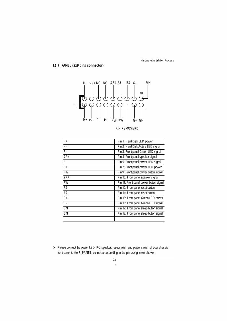
L) F_PANEL (2x9 pins connector)
Ø Please connect the power LED, PC speaker, reset switch and power switch of your chassisfront panel to the F_PANEL connector according to the pin assignment above.
H+ Pin 1: Hard Disk LED powerH- Pin 2: Hard Disk Active LED signalP- Pin 3: Front panel Green LED signalSPK Pin 4: Front panel speaker signalP- Pin 5: Front panel power LED signalP+ Pin 7: Front panel power LED powerPW Pin 9: Front panel power button signalSPK Pin 10: Front panel speaker signalPW Pin 11: Front panel power button signalRS Pin 12: Front panel reset buttonRS Pin 14: Front panel reset buttonG+ Pin 15: Front panel Green LED powerG- Pin 16: Front panel Green LED signalGN Pin 17: Front panel sleep button signalGN Pin 18: Front panel sleep button signal
1
RS G-
PIN REMOVERD
GN
18
GNG+
RSSPKSPKH-
H+ P- P- P+ PW
NC NC
PW
GA-8IEXW Motherboard
24
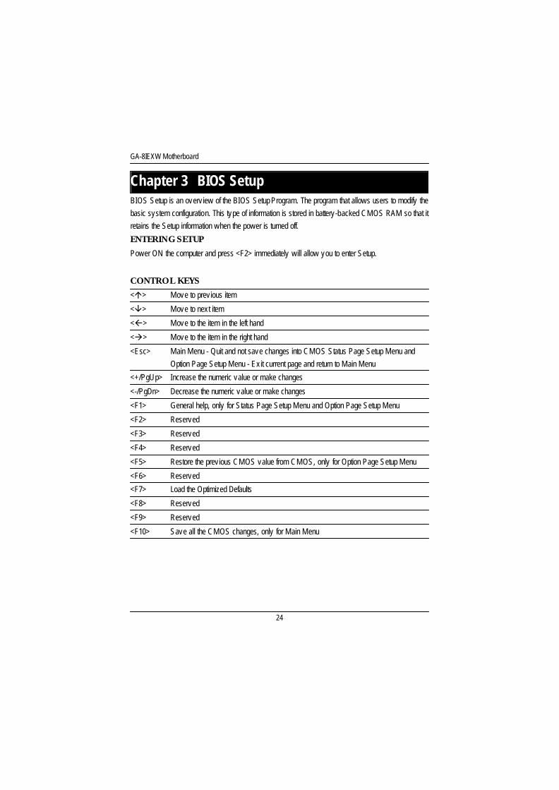
<á> Move to prev ious item
<â> Move to next item
<ß> Move to the item in the left hand
<à> Move to the item in the right hand
<Esc> Main Menu - Quit and not save changes into CMOS Status Page Setup Menu andOption Page Setup Menu - Ex it current page and return to Main Menu
<+/PgUp> Increase the numeric value or make changes
<-/PgDn> Decrease the numeric value or make changes
<F1> General help, only for Status Page Setup Menu and Option Page Setup Menu
<F2> Reserved
<F3> Reserved
<F4> Reserved
<F5> Restore the prev ious CMOS value from CMOS, only for Option Page Setup Menu
<F6> Reserved
<F7> Load the Optimized Defaults
<F8> Reserved
<F9> Reserved
<F10> Save all the CMOS changes, only for Main Menu
BIOS Setup is an overv iew of the BIOS Setup Program. The program that allows users to modify thebasic system configuration. This type of information is stored in battery-backed CMOS RAM so that itretains the Setup information when the power is turned off.
ENTERING SETUP
Power ON the computer and press <F2> immediately will allow you to enter Setup.
CONTROL KEYS
Chapter 3 BIOS Setup
BIOS Setup
25
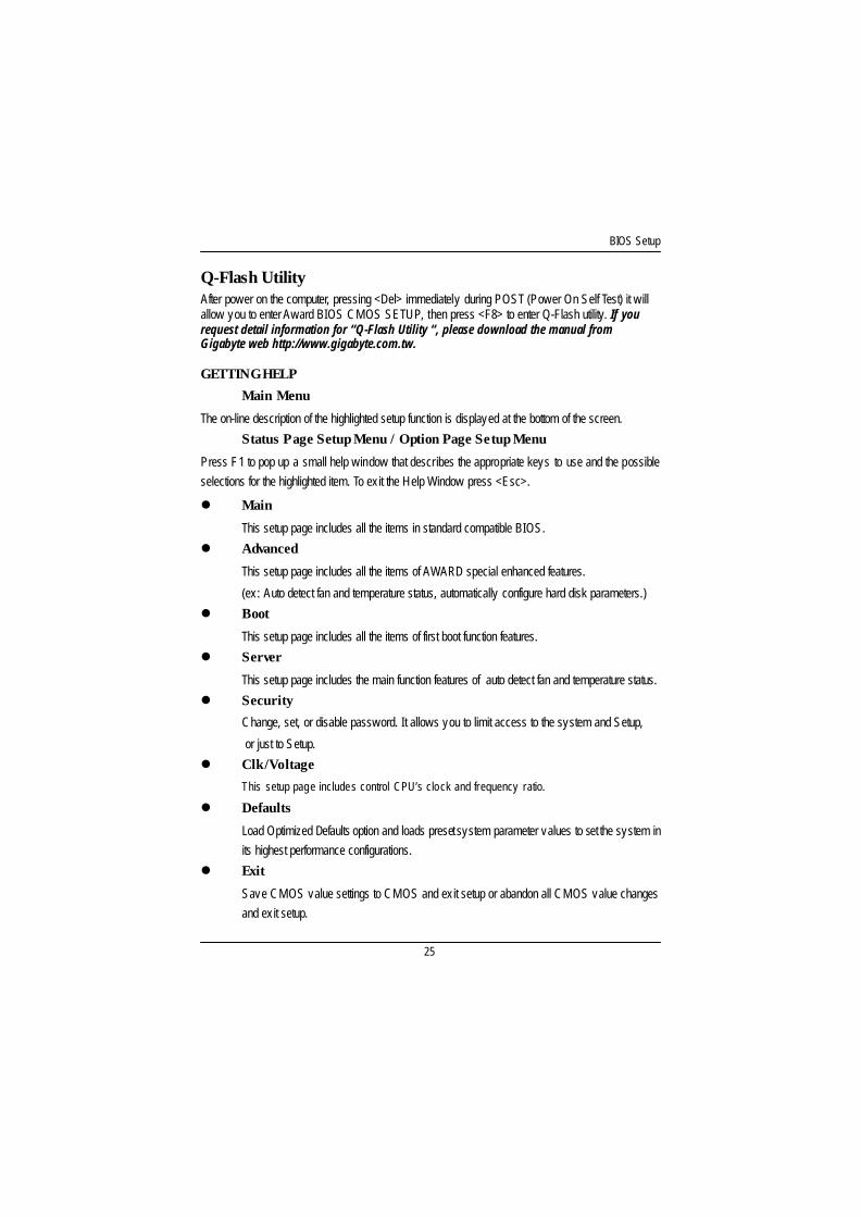
l Main
This setup page includes all the items in standard compatible BIOS.
l Advanced
This setup page includes all the items of AWARD special enhanced features.
(ex: Auto detect fan and temperature status, automatically configure hard disk parameters.)
l Boot
This setup page includes all the items of first boot function features.
l Server
This setup page includes the main function features of auto detect fan and temperature status.
l Security
Change, set, or disable password. It allows you to limit access to the system and Setup,
or just to Setup.
l Clk/Voltage
This setup page includes control CPU’s clock and frequency ratio.
l Defaults
Load Optimized Defaults option and loads preset system parameter values to set the system inits highest performance configurations.
l Exit
Save CMOS value settings to CMOS and ex it setup or abandon all CMOS value changesand ex it setup.
GETTING HELP
Main Menu
The on-line description of the highlighted setup function is displayed at the bottom of the screen.
Status Page Setup Menu / Option Page Setup Menu
Press F1 to pop up a small help window that describes the appropriate keys to use and the possibleselections for the highlighted item. To ex it the Help Window press <Esc>.
Q-Flash UtilityAfter power on the computer, pressing <Del> immediately during POST (Power On Self Test) it willallow you to enter Award BIOS CMOS SETUP, then press <F8> to enter Q-Flash utility. If yourequest detail information for “Q-Flash Utility “, please download the manual fromGigabyte web http://www.gigabyte.com.tw.
GA-8IEXW Motherboard
26
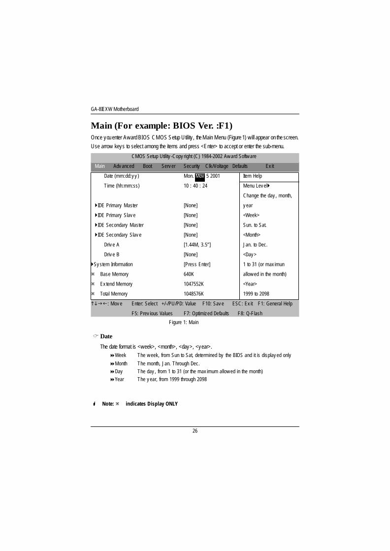
CDate
The date format is <week>, <month>, <day>, <year>.8Week The w eek, from Sun to Sat, determined by the BIOS and it is display ed only
8Month The month, Jan. Through Dec.8Day The day , from 1 to 31 (or the max imum allow ed in the month)8Year The y ear, from 1999 through 2098
H Note: ø indicates Display ONLY
Main (For example: BIOS Ver. :F1)Once you enter Award BIOS CMOS Setup Utility , the Main Menu (Figure 1) will appear on the screen.Use arrow keys to select among the items and press <Enter> to accept or enter the sub-menu.
Figure 1: Main
CMOS Setup Utility -Copy right (C) 1984-2002 Aw ard Softw are
Main Adv anced Boot Serv er Security Clk/Voltage Defaults Ex it
Date (mm:dd:y y ) Mon. Mov 5 2001 Item Help
Time (hh:mm:ss) 10 : 40 : 24 Menu Lev el}
Change the day , month,
}IDE Primary Master [None] y ear
}IDE Primary Slav e [None] <Week>
}IDE Secondary Master [None] Sun. to Sat.
}IDE Secondary Slav e [None] <Month>
Driv e A [1.44M, 3.5”] Jan. to Dec.
Driv e B [None] <Day >
}Sy stem Information [Press Enter] 1 to 31 (or max imun
ø Base Memory 640K allow ed in the month)
ø Ex tend Memory 1047552K <Year>
ø Total Memory 1048576K 1999 to 2098
higf: Mov e Enter: Select +/-/PU/PD: Value F10: Sav e ESC: Ex it F1: General Help
F5: Prev ious Values F7: Optimized Defaults F8: Q-Flash
BIOS Setup
27
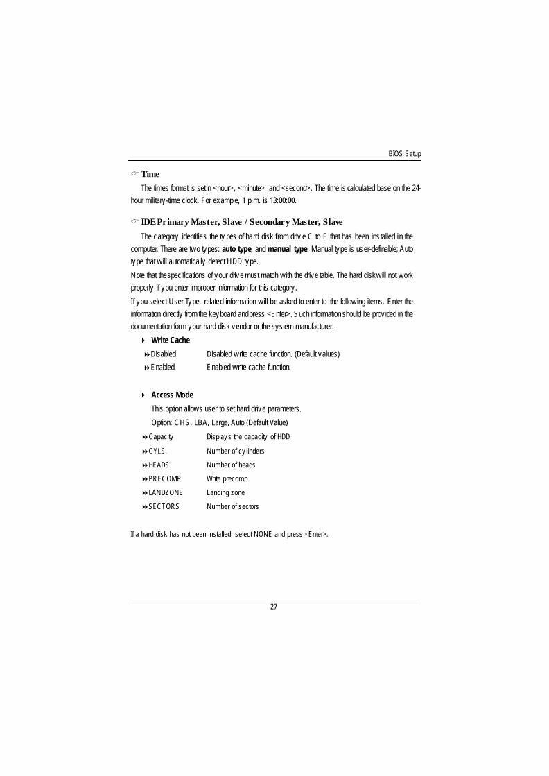
C IDE Primary Master, Slave / Secondary Master, Slave
The category identifies the ty pes of hard disk from driv e C to F that has been installed in thecomputer. There are two types: auto type, and manual type. Manual type is user-definable; Autotype that will automatically detect HDD type.
Note that the specifications of your drive must match with the drive table. The hard disk will not workproperly if you enter improper information for this category.
If you select User Type, related information will be asked to enter to the following items. Enter theinformation directly from the keyboard and press <Enter>. Such information should be prov ided in thedocumentation form your hard disk vendor or the system manufacturer.
4 Write Cache
8Disabled Disabled write cache function. (Default values)
8Enabled Enabled write cache function.
4 Access Mode
This option allows user to set hard drive parameters.
Option: CHS, LBA, Large, Auto (Default Value)
8Capacity Display s the capacity of HDD
8CYLS. Number of cy linders
8HEADS Number of heads
8PRECOMP Write precomp
8LANDZONE Landing zone
8SECTORS Number of sectors
If a hard disk has not been installed, select NONE and press <Enter>.
C Time
The times format is set in <hour>, <minute> and <second>. The time is calculated base on the 24-hour military-time clock. For example, 1 p.m. is 13:00:00.
GA-8IEXW Motherboard
28
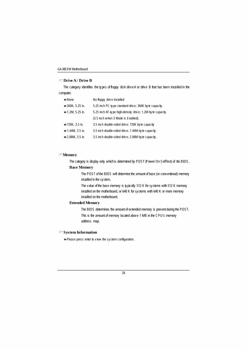
CDrive A / Drive B
The category identifies the types of floppy disk drive A or drive B that has been installed in the
computer.
8None No floppy driv e installed
8360K, 5.25 in. 5.25 inch PC-ty pe standard driv e; 360K by te capacity .
81.2M, 5.25 in. 5.25 inch AT-ty pe high-density driv e; 1.2M by te capacity
(3.5 inch w hen 3 Mode is Enabled).
8720K, 3.5 in. 3.5 inch double-sided driv e; 720K by te capacity
81.44M, 3.5 in. 3.5 inch double-sided driv e; 1.44M by te capacity .
82.88M, 3.5 in. 3.5 inch double-sided driv e; 2.88M by te capacity .
CMemory
The category is display-only which is determined by POST (Power On Self Test) of the BIOS.
Base Memory
The POST of the BIOS will determine the amount of base (or conventional) memoryinstalled in the system.
The value of the base memory is typically 512 K for systems with 512 K memoryinstalled on the motherboard, or 640 K for systems with 640 K or more memoryinstalled on the motherboard.
Extended Memory
The BIOS determines the amount of extended memory is present during the POST.
This is the amount of memory located above 1 MB in the CPU’s memoryaddress map.
C System Information
8Please press enter to v iew the sy stem configuration.
BIOS Setup
29
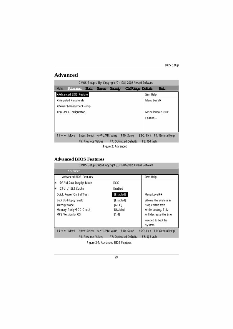
Advanced
Advanced BIOS Features
Figure 2-1: Adv anced BIOS Features
Figure 2: Adv anced
CMOS Setup Utility -Copy right (C) 1984-2002 Aw ard Softw are
Main Advanced Boot Server Security Clk/Voltage Defaults Exit}Adv anced BIOS Feature Item Help
}Integrated Peripherals Menu Lev el}
}Pow er Management Setup
}PnP/PCI Configuration Miscellaneous BIOS
Feature...
higf: Mov e Enter: Select +/-/PU/PD: Value F10: Sav e ESC: Ex it F1: General Help
F5: Prev ious Values F7: Optimized Defaults F8: Q-Flash
CMOS Setup Utility -Copy right (C) 1984-2002 Aw ard Softw are
Adv anced
Adv anced BIOS Features Item Help
ø DRAM Data Integrity Mode ECC
ø CPU L1 &L2 Cache Enabled
Quick Pow er On Self Test ` [Enabled] Menu Lev el}}
Boot Up Floppy Seek [Enabled] Allow s the sy stem toInterrupt Mode [APIC] skip certain testsMemory Parity /ECC Check Disabled w hile booting. ThisMPS Version for OS [1.4] w ill decrease the time
needed to boot thesy stem
higf: Mov e Enter: Select +/-/PU/PD: Value F10: Sav e ESC: Ex it F1: General Help
F5: Prev ious Values F7: Optimized Defaults F8: Q-Flash

GA-8IEXW Motherboard
30
CQuick Power On Self Test
This category speeds up Power On Self Test (POST) after you power on the computer. If it is set to
Enable, BIOS will shorten or skip some check items during POST.
8Enabled Enable quick POST. (Default Value)
8Disabled Normal POST.
C Boot Up Floppy Seek
During POST, BIOS will determine the floppy disk drive installed is 40 or 80 tracks. 360 K type is40 tracks; 720 K, 1.2 M and 1.44 M are all 80 tracks.
8Enabled BIOS searches for floppy disk driv e to determine it is 40 or 80 tracks. Note
that BIOS can not tell from 720 K, 1.2 M or 1.44 M driv e ty pe as they are
all 80tracks. (Default v alue)
8Disabled BIOS w ill not search for the ty pe of floppy disk driv e by track number. Note
that there w ill not be any w arning message if the driv e installed is 360 K.
CInterrupt Mode
8APIC Through IOAPIC generate more IRQ for sy stem use.(Default v alue)
8PIC Use AT stantard IRQ controller to generate IRQ.
When y ou already hav e IOAPIC enable sy stem and w ant to upgrade the sy stem please note, sincerunning an IOAPIC enabled OS (like Window s NT, Window s 2000, Window s XP...) sy stem w ith noneIOAPIC HW support w ill cause the sy stem to hang. Follow ing are some situations users might run into:
1.An IOAPIC enabled OS and change the BIOS setting from IOAPIC to PIC, this w ill cause y our sy stem
to hang.
CMemory Parity/ECC Check
This item w il l be av ai lable w hen y ou us e ECC memory .

BIOS Setup
31
CMPS Version Control For OS
This option allows user to set OS Multi Processors version. (Support Multi Processor Specificationrev ision 1.4)
Note: Some old MPS OS support 1.1 version only .
81.4 Support MPS Version 1.4 . (Default Value)
81.1 Support MPS Version 1.1.
GA-8IEXW Motherboard
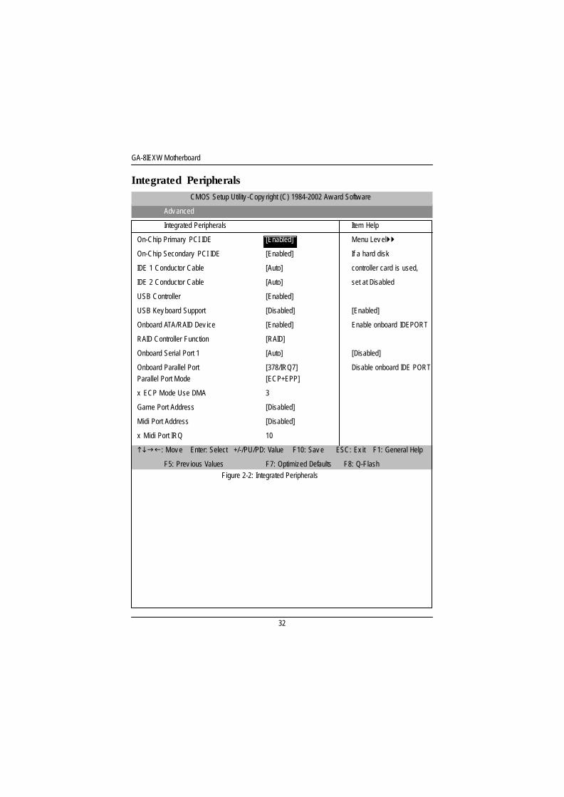
32
Integrated PeripheralsCMOS Setup Utility -Copy right (C) 1984-2002 Aw ard Softw are
Adv anced
Integrated Peripherals Item Help
On-Chip Primary PCI IDE [Enabled] Menu Lev el}}
On-Chip Secondary PCI IDE [Enabled] If a hard disk
IDE 1 Conductor Cable [Auto] controller card is used,
IDE 2 Conductor Cable [Auto] set at Disabled
USB Controller [Enabled]
USB Key board Support [Disabled] [Enabled]
Onboard ATA/RAID Dev ice [Enabled] Enable onboard IDEPORT
RAID Controller Function [RAID]
Onboard Serial Port 1 [Auto] [Disabled]
Onboard Parallel Port [378/IRQ7] Disable onboard IDE PORTParallel Port Mode [ECP+EPP]
x ECP Mode Use DMA 3
Game Port Address [Disabled]
Midi Port Address [Disabled]
x Midi Port IRQ 10
higf: Mov e Enter: Select +/-/PU/PD: Value F10: Sav e ESC: Ex it F1: General Help
F5: Prev ious Values F7: Optimized Defaults F8: Q-FlashFigure 2-2: Integrated Peripherals
BIOS Setup
33
C IDE 1/ 2 Conductor Cable8Auto Set this functio to auto detect IDE cable ty pe. (Default v alue)
8ATA66/100 Set conductor cable to ATA66/100
8ATA33 Set conductor cable to ATA33
CUSB Controller
8Enabled Enable USB Controller function. (Default v alue)
8Disabled Disable USB Controller function.
CUSB Keyboard Support
8Enabled Enable USB Key board Support.
8Disabled Disable USB Key board Support. (Default v alue)
CUSB Mouse Support
8Enabled Enable USB Mouse Support.
8Disabled Disable USB Mouse Support. (Default v alue)
COnboard ATA/RAID Devices
8Enabled Enable Onboard ATA/RAID Dev ice. (Default v alue)
8Disabled Disable Onboard ATA/RAID Dev ice.
CRAID Control ler Function
8RAID Set RAID Controller Function to RAID. (Default v alue)
8ATA Set RAID Controller Function to ATA.
GA-8IEXW Motherboard
34
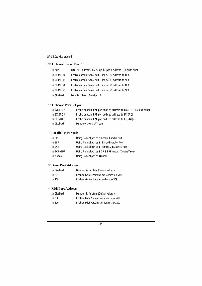
COnboard Serial Port 1
8Auto BIOS w ill automatically setup the port 1 address. (Default v alue)
83F8/IRQ4 Enable onboard Serial port 1 and set IO address to 3F8.
82F8/IRQ3 Enable onboard Serial port 1 and set IO address to 2F8.
83E8/IRQ4 Enable onboard Serial port 1 and set IO address to 3E8.
82E8/IRQ3 Enable onboard Serial port 1 and set IO address to 2E8.
8Disabled Disable onboard Serial port 1.
COnboard Parallel port8378/IRQ7 Enable onboard LPT port and set address to 378/IRQ7. (Default Value)
8278/IRQ5 Enable onboard LPT port and set address to 278/IRQ5.
83BC/IRQ7 Enable onboard LPT port and set address to 3BC/IRQ7.
8Disabled Disable onboard LPT port.
CParallel Port Mode
8SPP Using Parallel port as Standard Parallel Port.
8EPP Using Parallel port as Enhanced Parallel Port.
8ECP Using Parallel port as Ex tended Capabilities Port.
8ECP+EPP Using Parallel port as ECP & EPP mode. (Default Value)
8Normal Using Parallel port as Normal.
CGame Port Address
8Disabled Disable this function. (Default v alues)
8201 Enabled Game Port and set address to 201.
8209 Enabled Game Port and address to 209.
CMidi Port Address8Disabled Disable this function. (Default v alues)
8330 Enabled Midi Port and set address to 201.
8300 Enabled Midi Port and set address to 209.
BIOS Setup
35
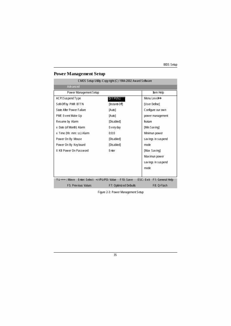
Power Management Setup
Figure 2-3: Pow er Management Setup
CMOS Setup Utility -Copy right (C) 1984-2002 Aw ard Softw are
Adv anced
Pow er Management Setup Item Help
ACPI Suspend Ty pe [Enabled] [S1 POS] Menu Lev el}}
Soft-Off by PWR BTTN [Instantt-Off] [User Define]
State After Pow er Failure [Auto] Configure our ow n
PME Ev ent Wake Up [Auto] pow er management
Resume by Alarm [Disabled] feature
x Date (of Month) Alarm Ev ery day [Min Sav ing]
x Time (hh: mm: ss) Alarm 0:0:0 Minimun pow er
Pow er On By Mouse [Disabled] sav ings in suspend
Pow er On By Key board [Disabled] mode
X KB Pow er On Passw ord Enter [Max Sav ing]
Max imun pow er
sav ings in suspend
mode
higf: Mov e Enter: Select +/-/PU/PD: Value F10: Sav e ESC: Ex it F1: General Help
F5: Prev ious Values F7: Optimized Defaults F8: Q-Flash

GA-8IEXW Motherboard
36
CACPI Suspend Type
8S1 Set suspend type to Power On Suspend under ACPI OS. (Default Value)
8S3 Set suspend ty pe to RAM under ACPI OS.
C Soft-off by PWR-BTTN
8Instant-off Press pow er button then Pow er off instantly . (Default v alue)
8Delay 4 Sec. Press pow er button 4 sec to Pow er off. Enter suspend if button is pressed less
than 4 sec.
C State After Power Failure
8Auto When AC-pow er back to the sy stem, the sy stem w ill return to the Last state
before AC-pow er off. (Default v alue)
8Off When AC-pow er back to the sy stem, the sy stem w ill be in "Off" state.
8On When AC-pow er back to the sy stem, the sy stem w ill be in "On" state.
C PME Event Wake UP
8Disabled Disable this function.
8Enabled Enable PME Ev ent Wake up. (Default Value)
C Wake Up On Ring
8Disabled Disable Wake Up On Ring function. (Default Value)
8Enabled Enable Wake Up On Ring function.
C Resume by Alarm
You can set "Resume by Alarm" item to enabled and key in Data/time to pow er on sy stem.
8Disabled Disable this function. (Default Value)
8Enabled Enable alarm function to POWER ON sy stem.
If RTC Alarm Lead To Pow er On is Enabled.
Date ( of Month) Alarm : Ev ery day , 1~31
Time ( hh: mm: ss) Alarm : (0~23) : (0~59) : (0~59)

BIOS Setup
37
C Power On By Mouse
8Disabled Disable this function. (Default Value)
8Mouse Click Mose double click to pow er sy stem.
C Power On By Keyboard
8Disabled Disable this function. (Default Value)
8Passw ord Enter from 1 to 5 characters to set the Key board Pow er On Passw ord.
8Key board 98 if y our key board has “key board 98” button, y ou can press the key to pow er ony our sy stem.
GA-8IEXW Motherboard
38
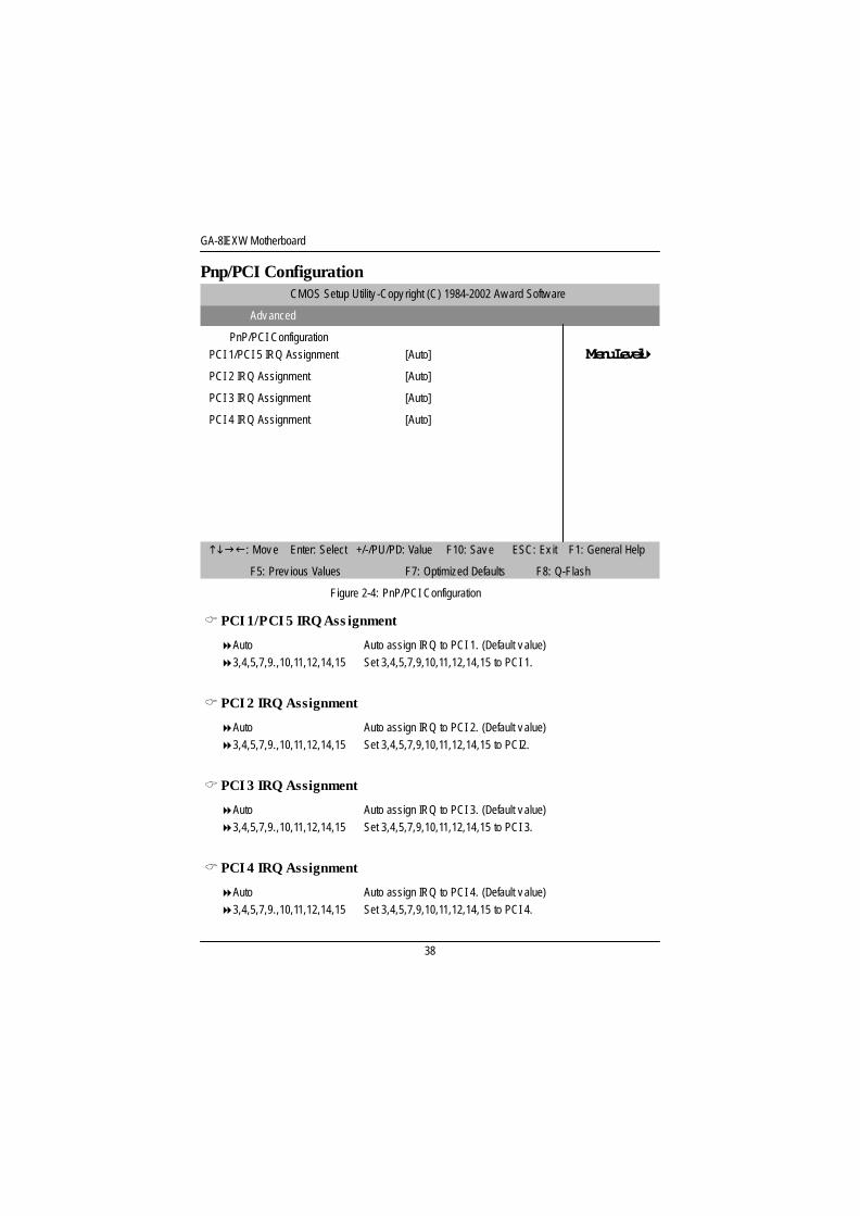
Pnp/PCI ConfigurationCMOS Setup Utility -Copy right (C) 1984-2002 Aw ard Softw are
Adv anced
PnP/PCI Configuration [Enabled] [PCI 1/PCI 5 IRQ Assignment [Auto] POS] Menu Level}}PCI 2 IRQ Assignment [Auto]
PCI 3 IRQ Assignment [Auto]
PCI 4 IRQ Assignment [Auto]
higf: Mov e Enter: Select +/-/PU/PD: Value F10: Sav e ESC: Ex it F1: General Help
F5: Prev ious Values F7: Optimized Defaults F8: Q-Flash
Figure 2-4: PnP/PCI Configuration
C PCI 1/PCI 5 IRQ Ass ignment
8Auto Auto assign IRQ to PCI 1. (Default v alue)83,4,5,7,9.,10,11,12,14,15 Set 3,4,5,7,9,10,11,12,14,15 to PCI 1.
C PCI 2 IRQ Assignment
8Auto Auto assign IRQ to PCI 2. (Default v alue)83,4,5,7,9.,10,11,12,14,15 Set 3,4,5,7,9,10,11,12,14,15 to PCI2.
C PCI 3 IRQ Assignment
8Auto Auto assign IRQ to PCI 3. (Default v alue)83,4,5,7,9.,10,11,12,14,15 Set 3,4,5,7,9,10,11,12,14,15 to PCI 3.
C PCI 4 IRQ Assignment
8Auto Auto assign IRQ to PCI 4. (Default v alue)83,4,5,7,9.,10,11,12,14,15 Set 3,4,5,7,9,10,11,12,14,15 to PCI 4.
BIOS Setup
39
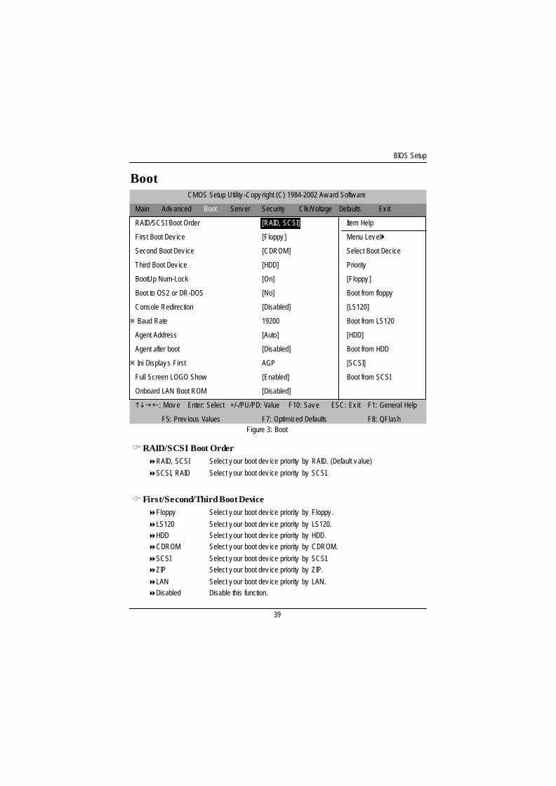
Boot
CRAID/SCSI Boot Order8RAID, SCSI Select y our boot dev ice priority by RAID. (Default v alue)
8SCSI, RAID Select y our boot dev ice priority by SCSI.
C First/Second/Third Boot Device8Floppy Select y our boot dev ice priority by Floppy .
8LS120 Select y our boot dev ice priority by LS120.8HDD Select y our boot dev ice priority by HDD.8CDROM Select y our boot dev ice priority by CDROM.
8SCSI Select y our boot dev ice priority by SCSI.8ZIP Select y our boot dev ice priority by ZIP.
8LAN Select y our boot dev ice priority by LAN.8Disabled Disable this function.
Figure 3: Boot
CMOS Setup Utility -Copy right (C) 1984-2002 Aw ard Softw are
Main Adv anced Boot Serv er Security Clk/Voltage Defaults Ex it
RAID/SCSI Boot Order [RAID, SCSI] Item Help
First Boot Dev ice [Floppy ] Menu Lev el}
Second Boot Dev ice [CDROM] Select Boot Decice
Third Boot Dev ice [HDD] Priority
BootUp Num-Lock [On] [Floppy ]
Boot to OS2 or DR-DOS [No] Boot from floppy
Console Redirection [Disabled] [LS120]
ø Baud Rate 19200 Boot from LS120
Agent Address [Auto] [HDD]
Agent after boot [Disabled] Boot from HDD
ø Ini Display s First AGP [SCSI]
Full Screen LOGO Show [Enabled] Boot from SCSI
Onboard LAN Boot ROM [Disabled]
higf: Mov e Enter: Select +/-/PU/PD: Value F10: Sav e ESC: Ex it F1: General Help
F5: Prev ious Values F7: Optimized Defaults F8: QFlash
GA-8IEXW Motherboard
40
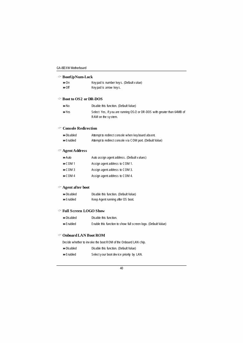
C BootUp Num-Lock8On Key pad is number key s. (Default v alue)8Off Key pad is arrow key s.
C Boot to OS2 or DR-DOS
8No Disable this function. (Default Value)
8Yes Select Yes, if y ou are running OS/2 or DR-DOS w ith greater than 64MB ofRAM on the sy stem.
C Console Redirection
8Disabled Attempt to redirect console w hen key board absent.
8Enabled Attempt to redirect console v ia COM port. (Default Value)
CAgent Address
8Auto Auto assign agent address. (Default v alues)
8COM 1 Assign agent address to COM 1.
8COM 3 Assign agent address to COM 3.
8COM 4 Assign agent address to COM 4.
C Agent after boot
8Disabled Disable this function. (Default Value)
8Enabled Keep Agent running after OS boot.
C Full Screen LOGO Show
8Disabled Disable this function.
8Enabled Enable this function to show full screen logo. (Default Value)
COnboard LAN Boot ROM
Decide w hether to inv oke the boot ROM of the Onboard LAN chip.
8Disabled Disable this function. (Default Value)
8Enabled Select y our boot dev ice priority by LAN.
BIOS Setup
41
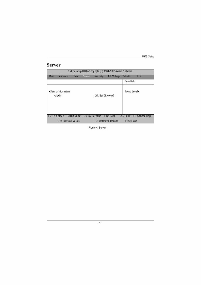
ServerCMOS Setup Utility -Copy right (C) 1984-2002 Aw ard Softw are
Main Adv anced Boot Serv er Security Clk/Voltage Defaults Ex it
Item Help
}Sensor Information Menu Lev el}Halt On [All, But Disk/Key ]
higf: Mov e Enter: Select +/-/PU/PD: Value F10: Sav e ESC: Ex it F1: General Help
F5: Prev ious Values F7: Optimized Defaults F8:Q-Flash
Figure 4: Serv er
GA-8IEXW Motherboard
42
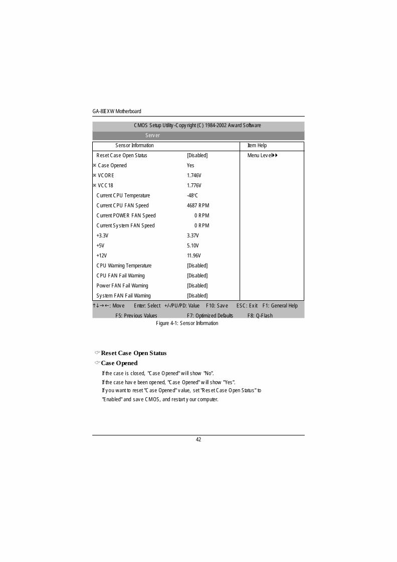
CReset Case Open Status
CCase Opened
If the case is closed, "Case Opened" w i ll show "No".
If the case hav e been opened, "Case Opened" w ill show "Yes".If y ou w ant to reset "C ase Opened" v alue, set "Res et Case Open Status" to
"Enabled" and sav e CM OS, and restart y our computer.
Figure 4-1: Sensor Information
CMOS Setup Utility -Copy right (C) 1984-2002 Aw ard Softw are
Serv er
Sensor Information Item Help
Reset Case Open Status [Disabled] Menu Lev el}}
ø Case Opened Yes
ø VCORE 1.746V
ø VCC18 1.776V
Current CPU Temperature -48oC
Current CPU FAN Speed 4687 RPM
Current POWER FAN Speed 0 RPM
Current Sy stem FAN Speed 0 RPM
+3.3V 3.37V
+5V 5.10V
+12V 11.96V
CPU Warning Temperature [Disabled]
CPU FAN Fail Warning [Disabled]
Pow er FAN Fail Warning [Disabled]
Sy stem FAN Fail Warning [Disabled]
higf: Mov e Enter: Select +/-/PU/PD: Value F10: Sav e ESC: Ex it F1: General Help
F5: Prev ious Values F7: Optimized Defaults F8: Q-Flash
BIOS Setup
43
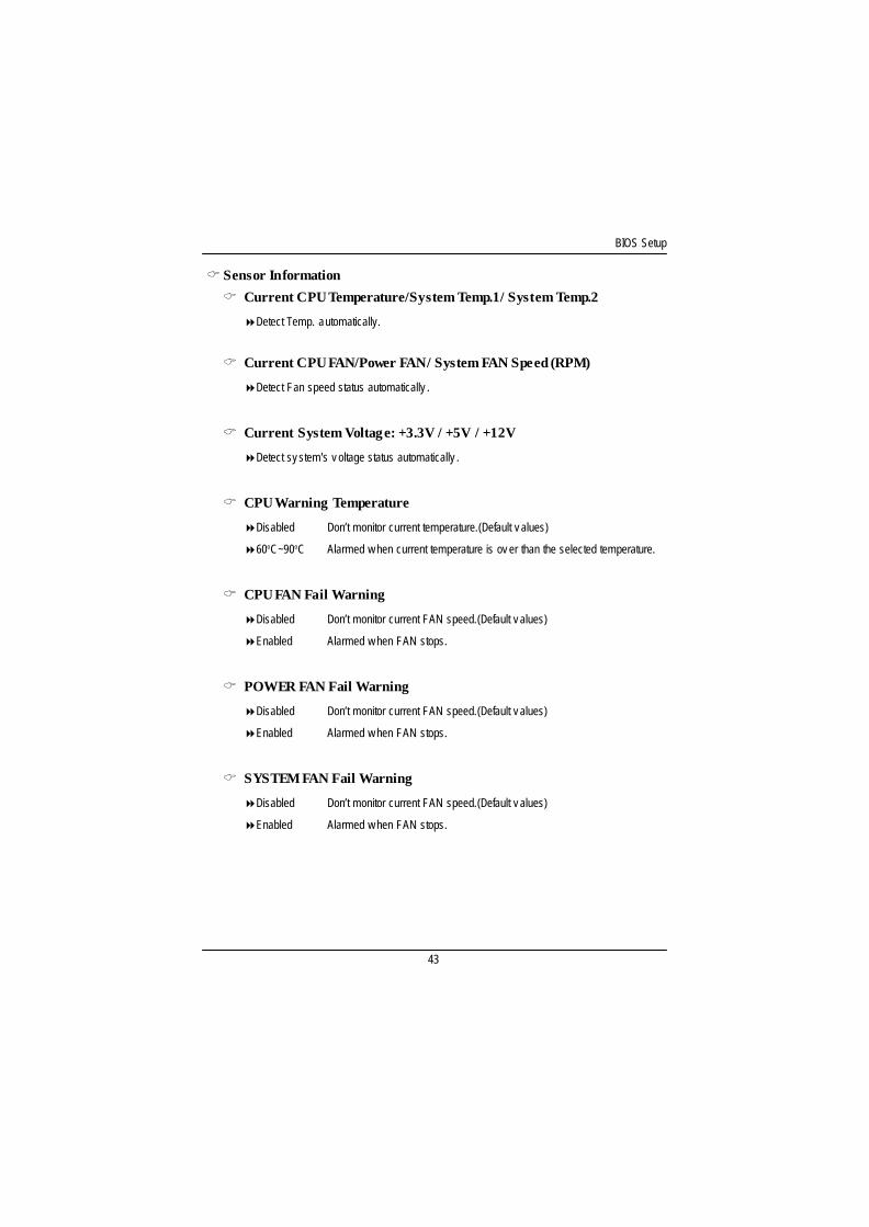
C Sensor Information
C Current CPU Temperature/System Temp.1/ System Temp.2
8Detect Temp. automatically.
C Current CPU FAN/Power FAN/ System FAN Speed (RPM)
8Detect Fan speed status automatically .
C Current System Voltage: +3.3V / +5V / +12V
8Detect sy stem's v oltage status automatically .
C CPU Warning Temperature
8Disabled Don’t monitor current temperature.(Default v alues)
860oC~90oC Alarmed w hen current temperature is ov er than the selected temperature.
C CPU FAN Fail Warning
8Disabled Don’t monitor current FAN speed.(Default v alues)
8Enabled Alarmed w hen FAN stops.
C POWER FAN Fail Warning
8Disabled Don’t monitor current FAN speed.(Default v alues)
8Enabled Alarmed w hen FAN stops.
C SYSTEM FAN Fail Warning
8Disabled Don’t monitor current FAN speed.(Default v alues)
8Enabled Alarmed w hen FAN stops.

GA-8IEXW Motherboard
44
CHalt On
The category determines whether the computer will stop if an error is detected during power up.
8NO Errors The system boot w ill not stop for any error that may be detected and y ou
w ill be prompted.
8All Errors Whenev er the BIOS detects a non-fatal error the sy stem w ill be stopped.
8All, But Key board The sy stem boot w ill not stop for a key board error, and it w ill stop for allother errors.
8All, But Diskette The sy stem boot w ill not stop for a disk error; it w ill stop for all othererrors.
8All, But Disk/Key The sy stem boot w ill not stop for a key board or disk error; it w ill stop for
all other errors.(Default v alue)
BIOS Setup
45
CMOS Setup Utility -Copy right (C) 1984-2002 Aw ard Softw are
Main Adv anced Boot Serv er Security Clk/Voltage Defaults Ex it
Set Superv isor Passw ord Item Help
Set User Passw ord Menu Lev el}
Passw ord Check [Setup] Change/Set/Disable
Passw ord
higf: Mov e Enter: Select +/-/PU/PD: Value F10: Sav e ESC: Ex it F1: General Help
F5: Prev ious Values F7: Optimized Defaults F8: Q-Flash
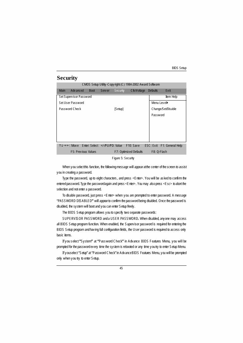
Security
When you select this function, the following message will appear at the center of the screen to assistyou in creating a password.
Type the password, up to eight characters , and press <Enter>. You will be asked to confirm theentered password. Type the password again and press <Enter>. You may also press <Esc> to abort theselection and not enter a password.
To disable password, just press <Enter> when you are prompted to enter password. A message“PASSWORD DISABLED” will appear to confirm the password being disabled. Once the password isdisabled, the system will boot and you can enter Setup freely .
The BIOS Setup program allows you to specify two separate passwords:
SUPERVISOR PASSWORD and a USER PASSWORD. When disabled, anyone may accessall BIOS Setup program function. When enabled, the Superv isor password is required for entering theBIOS Setup program and having full configuration fields, the User password is required to access onlybasic items.
If you select “System” at “Password Check” in Advance BIOS Features Menu, you wil l beprompted for the password every time the system is rebooted or any time you try to enter Setup Menu.
If you select “Setup” at “Password Check” in Advance BIOS Features Menu, you will be promptedonly when you try to enter Setup.
Figure 5: Security

GA-8IEXW Motherboard
46
C Password Check
8System The system can not boot and can not access to Setup page will be denied
if the correct passw ord is not entered at the prompt.
8Setup The sy stem w ill boot, but access to Setup w ill be denied if the correct
passw ord is not entered at the prompt. (Default v alue)
BIOS Setup
47
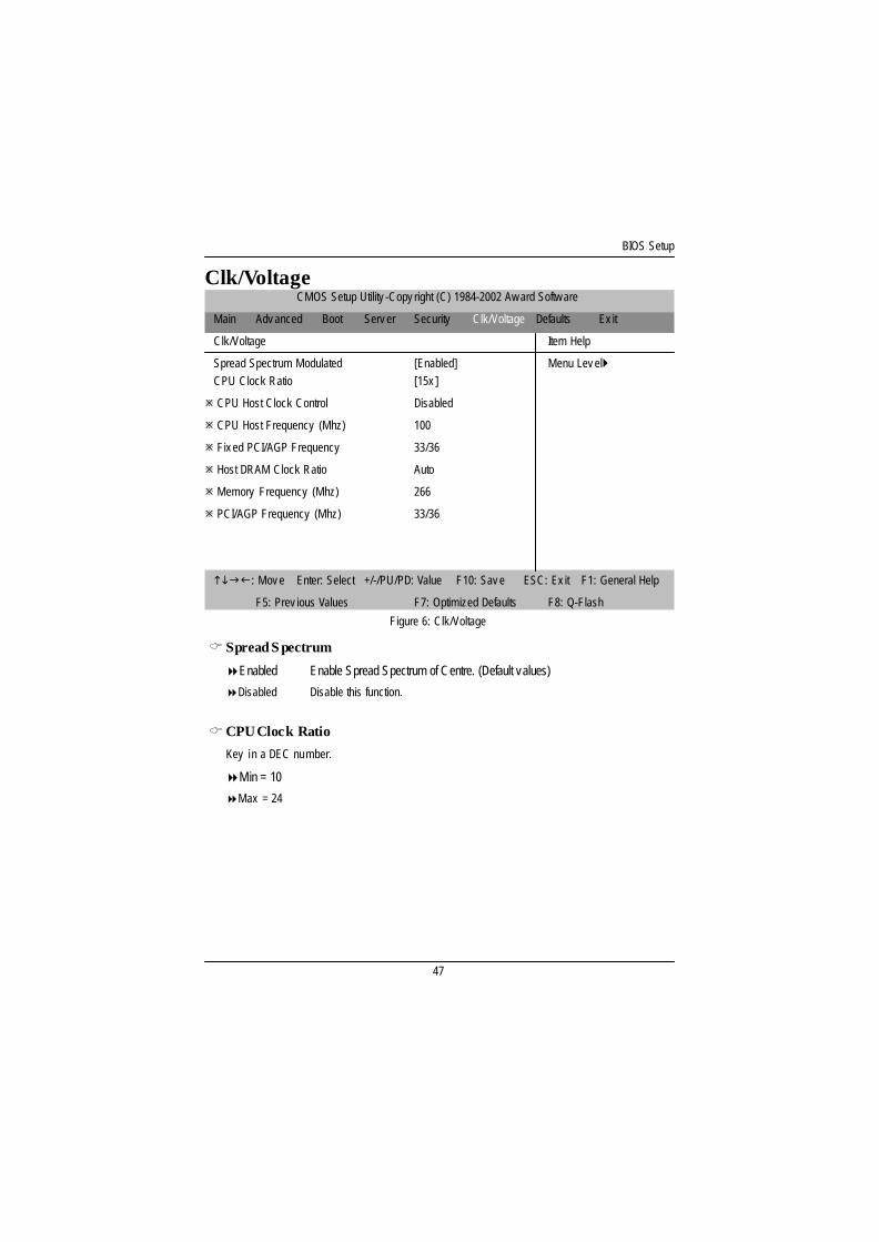
Clk/VoltageCMOS Setup Utility -Copy right (C) 1984-2002 Aw ard Softw are
Main Adv anced Boot Serv er Security Clk/Voltage Defaults Ex it
Clk/Voltage Item Help
Spread Spectrum Modulated [Enabled] Menu Lev el}CPU Clock Ratio [15x ]
ø CPU Host Clock Control Disabled
ø CPU Host Frequency (Mhz) 100
ø Fix ed PCI/AGP Frequency 33/36
ø Host DRAM Clock Ratio Auto
ø Memory Frequency (Mhz) 266
ø PCI/AGP Frequency (Mhz) 33/36
higf: Mov e Enter: Select +/-/PU/PD: Value F10: Sav e ESC: Ex it F1: General Help
F5: Prev ious Values F7: Optimized Defaults F8: Q-Flash
Figure 6: Clk/Voltage
C Spread S pectrum
8Enabled Enable Spread Spectrum of Centre. (Default values)
8Disabled Disable this function.
CCPU Clock Ratio
Key in a DEC number.
8Min = 10
8Max = 24
GA-8IEXW Motherboard
48
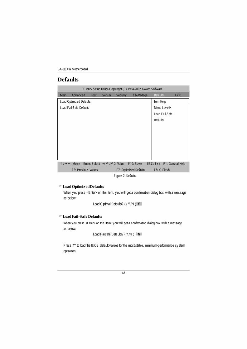
CMOS Setup Utility -Copy right (C) 1984-2002 Aw ard Softw are
Main Adv anced Boot Serv er Security Clk/Voltage Defaults Ex it
Load Optimized Defaults Item Help
Load Fail-Safe Defaults Menu Lev el}
Load Fail-Safe
Defaults
higf: Mov e Enter: Select +/-/PU/PD: Value F10: Sav e ESC: Ex it F1: General Help
F5: Prev ious Values F7: Optimized Defaults F8: Q-Flash
Defaults
CLoad Optimized DefaultsWhen you press <Enter> on this item, you will get a confirmation dialog box with a messageas below:
Load Optimal Defaults? ( ( Y/N ) Y
CLoad Fail-Safe Defaults
When y ou press <Enter> on this item, y ou w ill get a confirmation dialog box w ith a message
as below :
Load Failsafe Defaults? ( Y/N ) N
Press ‘Y’ to load the BIOS default values for the most stable, minimum-performance systemoperation.
Figure 7: Defaults
BIOS Setup
49
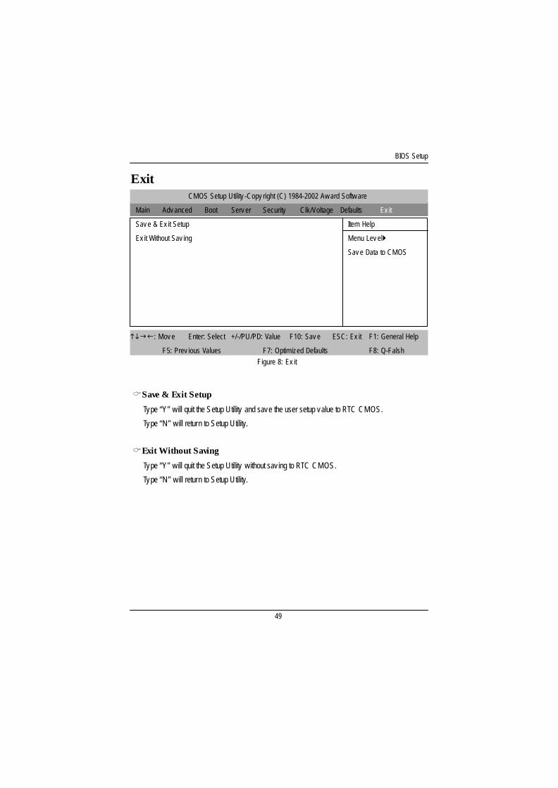
CMOS Setup Utility -Copy right (C) 1984-2002 Aw ard Softw are
Main Adv anced Boot Serv er Security Clk/Voltage Defaults Ex it
Sav e & Ex it Setup Item Help
Ex it Without Sav ing Menu Lev el}
Sav e Data to CMOS
higf: Mov e Enter: Select +/-/PU/PD: Value F10: Sav e ESC: Ex it F1: General Help
F5: Prev ious Values F7: Optimized Defaults F8: Q-Falsh
Exit
CSave & Exit Setup
Type “Y” will quit the Setup Utility and save the user setup value to RTC CMOS.
Type “N” will return to Setup Utility.
CExit Without Saving
Type “Y” will quit the Setup Utility without sav ing to RTC CMOS.
Type “N” will return to Setup Utility.
Figure 8: Ex it
GA-8IDXR Motherboard
50
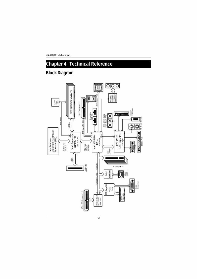
Revision HistoryChapter 4 Technical Reference
Block Diagram
51
Appendix
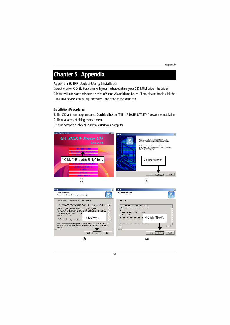
Revision HistoryChapter 5 AppendixAppendix A: INF Update Utility InstallationInsert the driver CD-title that came with your motherboard into your CD-ROM driver, the driverCD-title will auto start and show a series of Setup Wizard dialog boxes. If not, please double click theCD-ROM device icon in "My computer", and execute the setup.exe.
Installation Procedures:1. The CD auto run program starts, Double click on “INF UPDATE UTILITY” to start the installation.2. Then, a series of dialog boxes appear.3.Setup completed, click “Finish” to restart your computer.
(2)
(3) (4)
(1)
1.Click "INF Update Utility" item. 2.Click "Next".
3.Click "Yes". 4.Click "Next".
GA-8IEXW Motherboard
52
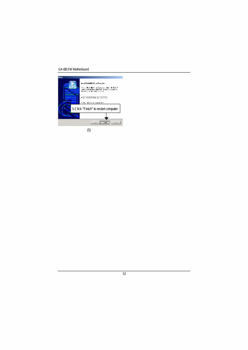
(5)
5.Click "Finish" to restart computer.
53
Appendix
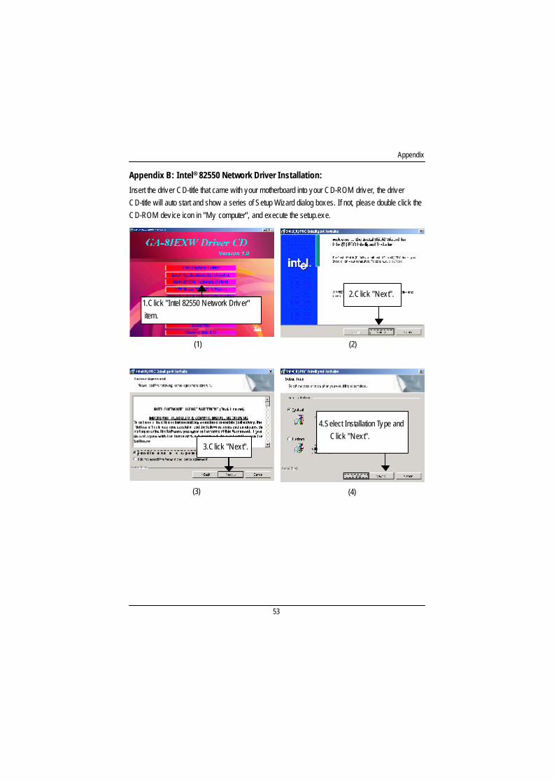
Insert the driver CD-title that came with your motherboard into your CD-ROM driver, the driverCD-title will auto start and show a series of Setup Wizard dialog boxes. If not, please double click theCD-ROM device icon in "My computer", and execute the setup.exe.
(2)
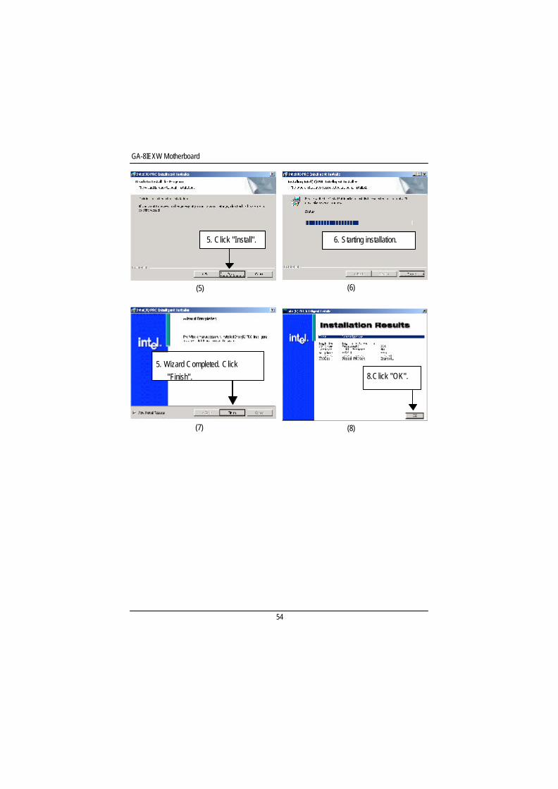
Appendix B: Intel® 82550 Network Driver Installation:
1.Click "Intel 82550 Network Driver" item.
2.Click "Next".
(1)
(3)
3.Click "Next".
(4)
4.Select Installation Type andClick "Next".
GA-8IEXW Motherboard
54
(5)
6. Starting installation.5. Click "Install".
(6)
5. Wizard Completed. Click"Finish".
(8)(7)
8.Click "OK".
55
Appendix
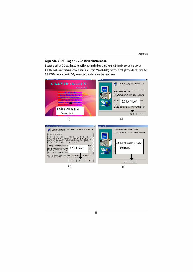
Appendix C: ATI-Rage XL VGA Driver InstallationInsert the driver CD-title that came with your motherboard into your CD-ROM driver, the driverCD-title will auto start and show a series of Setup Wizard dialog boxes. If not, please double click theCD-ROM device icon in "My computer", and execute the setup.exe.
(1) (2)
1. Click "ATI-Rage XLDriver" item.
3.Click "Yes".
(3) (4)
2.Click "Next".
4.Click "Finishl" to restartcomputer.
GA-8IEXW Motherboard
56
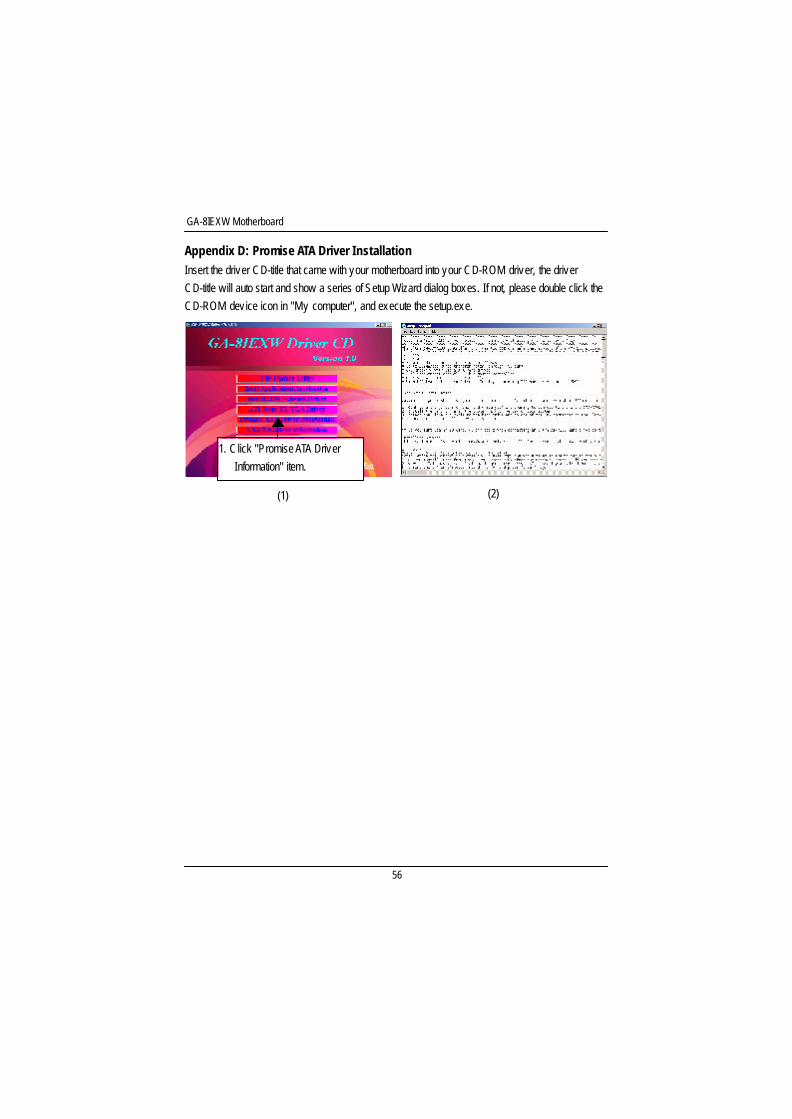
Appendix D: Promise ATA Driver InstallationInsert the driver CD-title that came with your motherboard into your CD-ROM driver, the driverCD-title will auto start and show a series of Setup Wizard dialog boxes. If not, please double click theCD-ROM device icon in "My computer", and execute the setup.exe.
1. Click "Promise ATA DriverInformation" item.
(1) (2)
57
Appendix
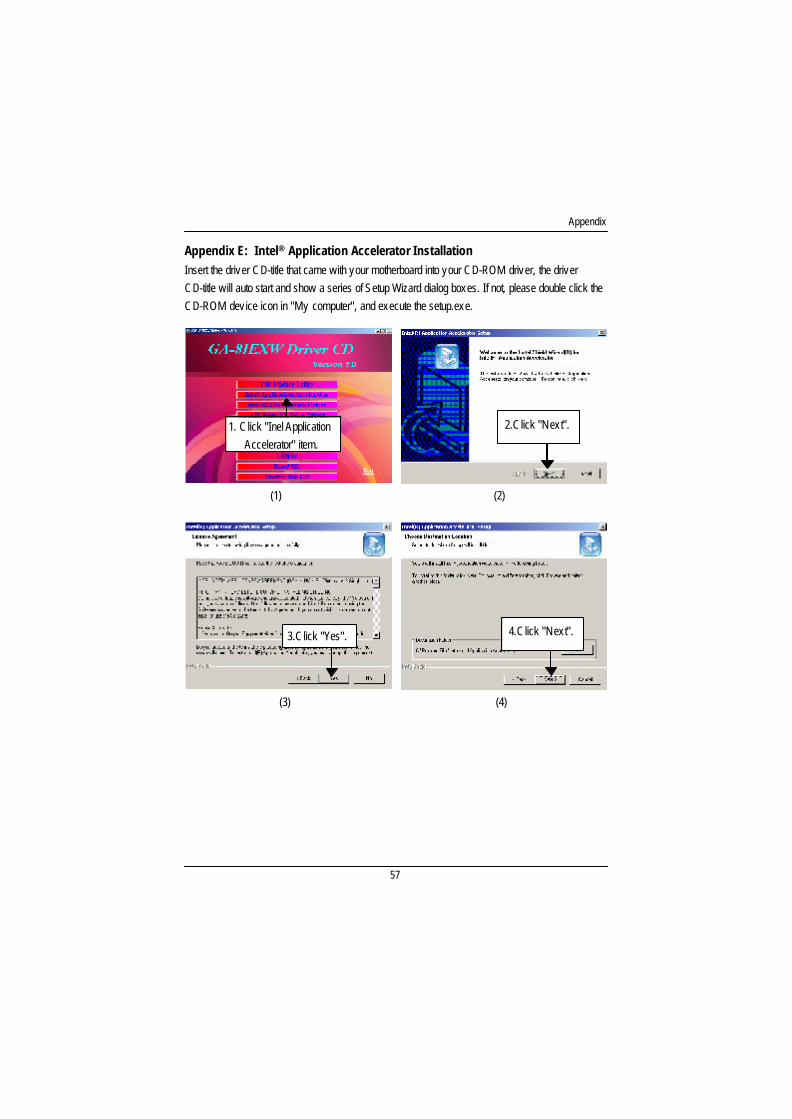
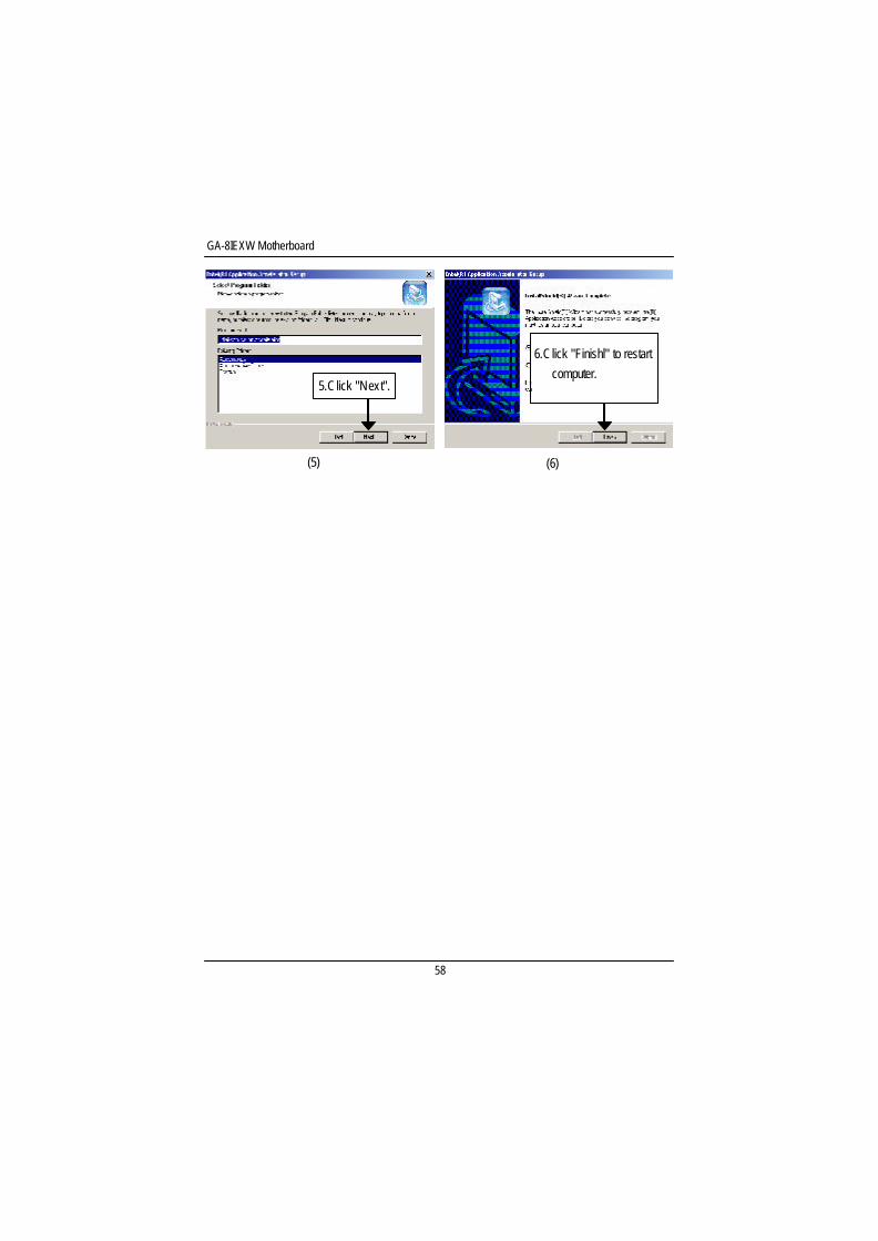
Appendix E: Intel® Application Accelerator InstallationInsert the driver CD-title that came with your motherboard into your CD-ROM driver, the driverCD-title will auto start and show a series of Setup Wizard dialog boxes. If not, please double click theCD-ROM device icon in "My computer", and execute the setup.exe.
(1) (2)
3.Click "Yes".
(3) (4)
2.Click "Next".1. Click "Inel ApplicationAccelerator" item.
4.Click "Next".
GA-8IEXW Motherboard
58
(5)
5.Click "Next".
(6)
6.Click "Finishl" to restartcomputer.
59
Appendix
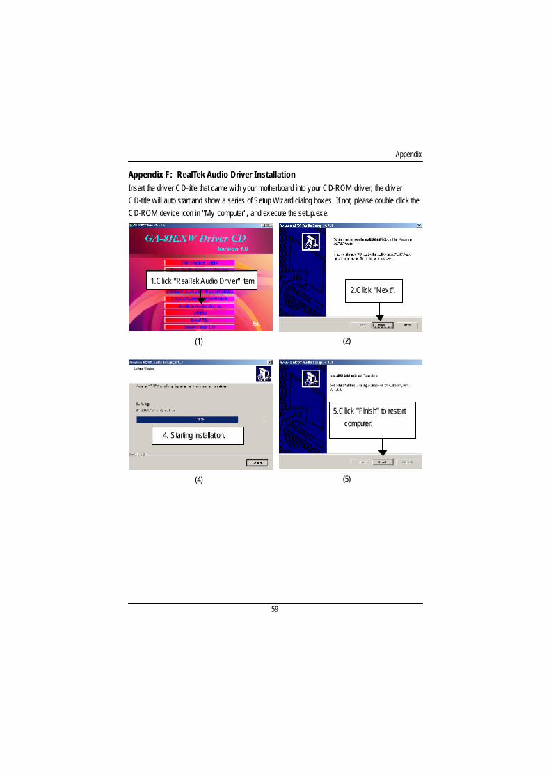
Appendix F: RealTek Audio Driver InstallationInsert the driver CD-title that came with your motherboard into your CD-ROM driver, the driverCD-title will auto start and show a series of Setup Wizard dialog boxes. If not, please double click theCD-ROM device icon in "My computer", and execute the setup.exe.
1.Click "RealTek Audio Driver" item
(2)
(4)
(1)
2.Click "Next".
(5)
4. Starting installation.
5.Click "Finish" to restartcomputer.
GA-8IEXW Motherboard
60
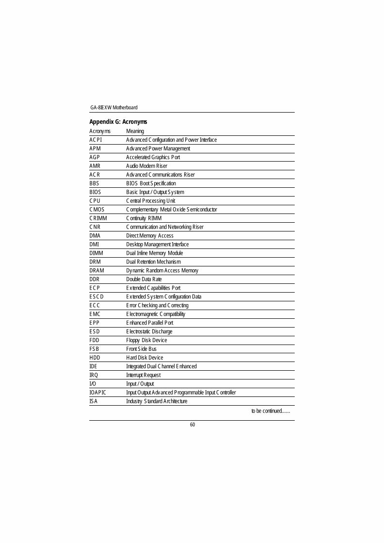
Appendix G: AcronymsAcronyms MeaningACPI Advanced Configuration and Power InterfaceAPM Advanced Power ManagementAGP Accelerated Graphics PortAMR Audio Modem RiserACR Advanced Communications RiserBBS BIOS Boot SpecificationBIOS Basic Input / Output SystemCPU Central Processing UnitCMOS Complementary Metal Oxide SemiconductorCRIMM Continuity RIMMCNR Communication and Networking RiserDMA Direct Memory AccessDMI Desktop Management InterfaceDIMM Dual Inline Memory ModuleDRM Dual Retention MechanismDRAM Dynamic Random Access MemoryDDR Double Data RateECP Extended Capabilities PortESCD Extended System Configuration DataECC Error Checking and CorrectingEMC Electromagnetic CompatibilityEPP Enhanced Parallel PortESD Electrostatic DischargeFDD Floppy Disk DeviceFSB Front Side BusHDD Hard Disk DeviceIDE Integrated Dual Channel EnhancedIRQ Interrupt RequestI/O Input / OutputIOAPIC Input Output Advanced Programmable Input ControllerISA Industry Standard Architecture
to be continued......
61
Appendix
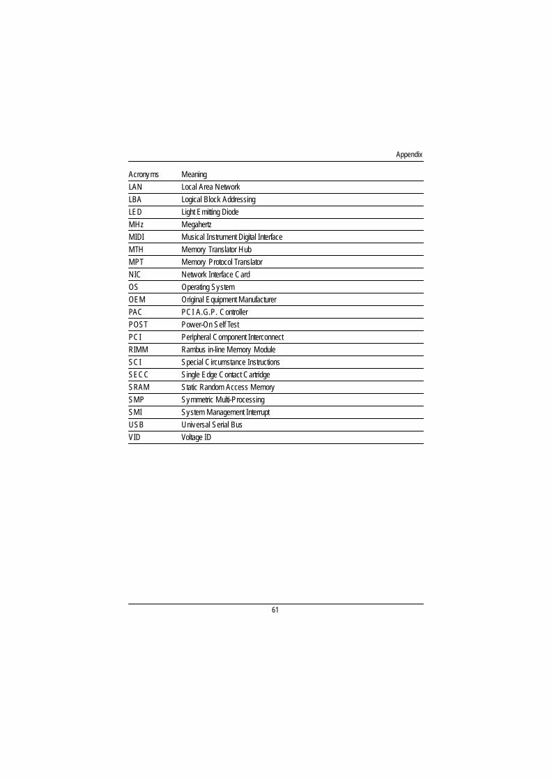
Acronyms MeaningLAN Local Area NetworkLBA Logical Block AddressingLED Light Emitting DiodeMHz MegahertzMIDI Musical Instrument Digital InterfaceMTH Memory Translator HubMPT Memory Protocol TranslatorNIC Network Interface CardOS Operating SystemOEM Original Equipment ManufacturerPAC PCI A.G.P. ControllerPOST Power-On Self TestPCI Peripheral Component InterconnectRIMM Rambus in-line Memory ModuleSCI Special Circumstance InstructionsSECC Single Edge Contact CartridgeSRAM Static Random Access MemorySMP Symmetric Multi-ProcessingSMI System Management InterruptUSB Universal Serial BusVID Voltage ID
GA-8IEXW Motherboard
62
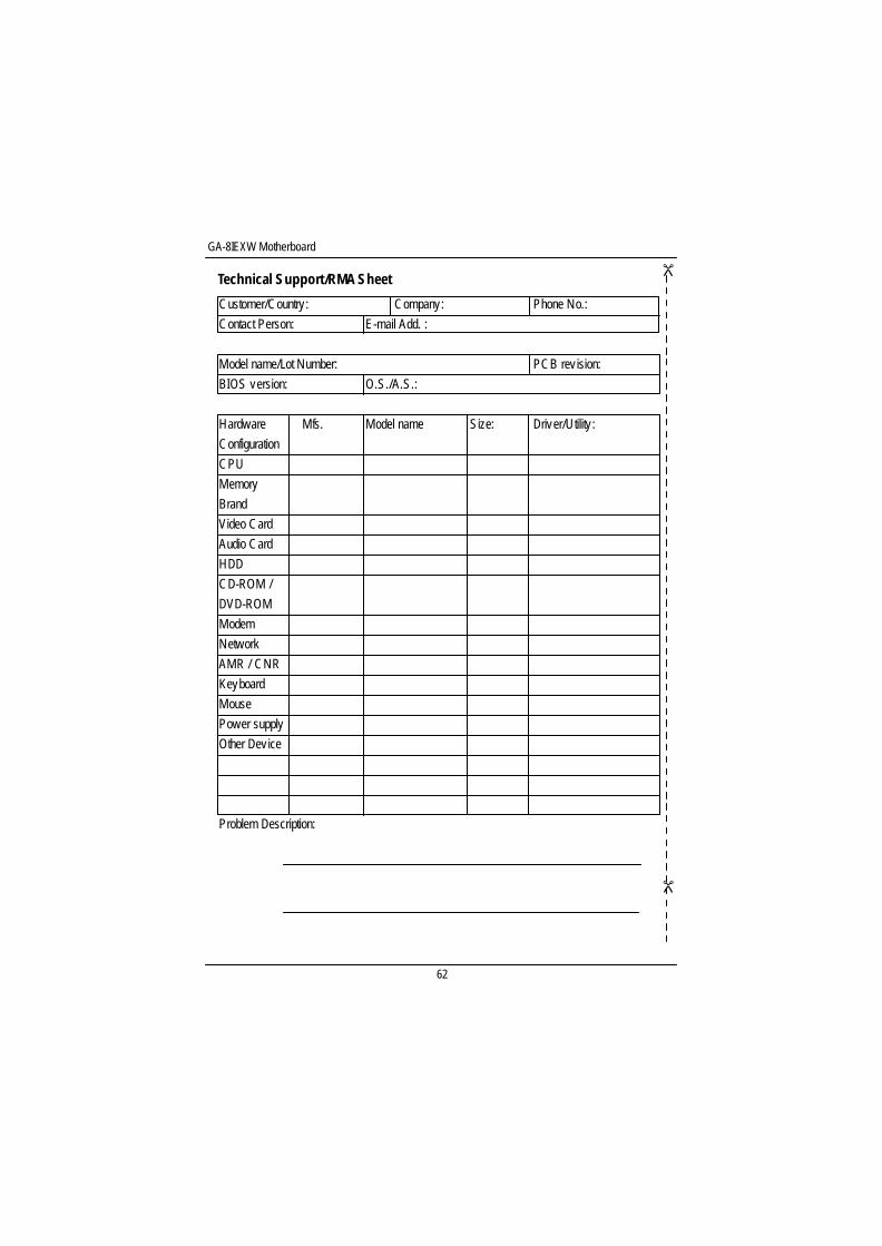
Technical Support/RMA Sheet
Customer/Country : Company: Phone No.:Contact Person: E-mail Add. :
Model name/Lot Number: PCB rev ision:BIOS version: O.S./A.S.:
Hardware Mfs. Model name Size: Driver/Utility :ConfigurationCPUMemoryBrandVideo CardAudio CardHDDCD-ROM /DVD-ROMModemNetworkAMR / CNRKeyboardMousePower supplyOther Device
Problem Description:
&&