Embed Size (px)
Citation preview

Working Drawing Review Procedures September 17, 2013
1
Working Drawing Review Procedures
2013 INDOT Bridge Design Conference
Jim Reilman, MS, PEField Engineer, INDOT
2013 INDOT Bridge Design Conference, September 17, 2013
101.74 Working DrawingsSupplementary bridge plans, stress
sheets, shop drawings, erection plans, falsework plans, framework plans, cofferdam plans, bending diagrams for reinforcement, or any other supplementary plans, detailed drawings, design drawings, or similar data which the Contractor is required to submit for approval. - INDOT Standard Specifications
Definition

Working Drawing Review Procedures September 17, 2013
2
105.02 Plans and Working Drawings� References 101.74
� Drawings and Calculations submitted in acceptable format. A longhand example may be requested.
� Generally required to be signed & sealed by professional engineer (defined in 101.37 as licensed in Indiana). There are a few exceptions.
� 14 calendar days are allotted for review.
Specification
� Authorized alterations or changes� must be identified by thecontractor, commonly thru anRFI. When RFI approved, thechange can be shown on thedrawings.
� Unauthorized changes are not acceptable. Can’t just “sneak” something by, hoping the reviewer misses it and approves the drawing.
RFI
Working Drawing Review Procedures September 17, 2013
3
� Contractor is still responsible for dimensions, accuracy, and fit of work.
� Often, working drawings are simply additional detailing of the design plans.
� Other times, the contractor is required to design a portion of the work.
� Shop plan review can interfere with construction schedule and cause delays
� Often submittals are electronic
� Document when plans come in, when they go out AND what; page numbers, type of
items reviewed, and items reviewed.
slide content used with permission of:
Submittals

Working Drawing Review Procedures September 17, 2013
4
� Document all correspondence with suppliers and make sure responsible engineer is aware of ALL conversations and e-mails.
� 105.02 – All working drawings and design calculations shall include the contract number, Contractor’s name, and contact
person.
Submittals
slide content used with permission of:
Contract Document Hierarchy� Contract Document Hierarchy (105.04)
� Contract requirements are intended to be complementary!
In case of discrepancy, the following relationships apply:

Working Drawing Review Procedures September 17, 2013
5
Contract Document Hierarchy
Instructions to Bidders
Pay Items
Special Provisions
Plans
Supplemental Specifications
Standard Specifications
SS 105.04 line 130:Notes on plans which are not also included in either the special provisions or among the general notes portion of the plans, and refer to payment, non-payment, or cost to be included in that of other pay items, will not govern over specifications. X
Construction Memorandum 09-13, dated June 11, 2009 established that the LPA is responsible for review of all shop drawings & falsework plans. This memo has since been incorporated into Construction Memorandum 11-02.
Working Drawing Review

Working Drawing Review Procedures September 17, 2013
6
For INDOT contracts� outlines the responsible party for review of the respective submittal.
For LPA contracts� indicates that the LPA is responsible for review of the submittals
For design-build contracts working drawing review is contract-specific.
Construction Memo 11-02
� Structural Members & Items
� MSE Walls
� Sound Barrier Systems
� Precast Concrete Culverts
� Traffic Items
� Falsework & Temporary Bridge Drawings
� Permanent Metal Deck Forms
� Foundation Seals & Deck Pour Sequences
� Stream Crossings & Work Bridges
� Miscellaneous
Types of Working Drawings

Working Drawing Review Procedures September 17, 2013
7
What & Why are you checking?
� Review is a limited review for general compliance with the contract documents(specifications, standard drawings, design plans, contract provisions) No responsibility is assumed for correctness of dimensions or details.
� Each firm is encouraged to decide to what degree of “limited” they wish their employees to review to.
Working Drawings
� The reviewer is encouraged to check general site features and some dimensions.
� Remember, the contractor is responsible for the quality control review of the submittal.
� The reviewer should not VE the submittal
Working Drawings

Working Drawing Review Procedures September 17, 2013
8
� Rolled Steel Beams
� Welded Plate Girders
� Precast Prestressed Concrete Members
� Elastomeric Bearings
� Steel Fixed & Expansion
Bearings
� Expansion Joint
� SS
� Modular
Structural Members & Items
� These items are designed by the designer
of record.
� The contractor or his representative performs additional detailing as necessary to fabricate the structuralmember.
Structural Members & Items
Submit a copy of approved drawings to INDOT for structural members [email protected] X

Working Drawing Review Procedures September 17, 2013
9
1. Beam Type
2. Beam Cross Section
3. Top Steel reinforcement
4. Bottom Stirrup end reinforcement
5. Bridge skew
6. Number of beams
Precast Prestressed Concrete
7. Internal strand pull
8. Concrete strength initial and 28 day
9. Beam scoring
10. Water proofing and surface treatments
11. Reinforcing Bar Grade
12. Epoxy Coating of Reinforcement
13. Insert Placement – skew or square
slide content used with permission of:
14. Bearing Pad Quantity
15. Strand Pattern, number, diameter, strength, debonding
16. Stirrup Spacing
17. End Reinforcement
18. Internal strand bend detail
19. Beam Block Out
20. Beam Notch
21. Special Beam Notes
22. Concrete Unit Weight
Precast Prestressed Concrete
slide content used with permission of:

Working Drawing Review Procedures September 17, 2013
10
1. Framing Plan Dimensions
2. Splice Details( plate sizes, gages, filler plates)
3. Diaphragm Details (Plate Sizes, connection details, welds)
4. Beam Layout (Material, lengths, diaphragm locations)
5. Material Grades
6. Shear Studs (size, number, location)
7. Camber, Sweep, and Reaming Diagrams
8. Painting Requirements
9. Special Plan Notes
Steel Girders & Beams
slide content used with permission of:
Steel Beam/Girder
� Weld Types
� Camber offset Baseline
� Girder length dimensions
Bearings
� Thickness to gauge
� Available steel grade
Prestressed Beams
� Lifting Loop addition
� Strand location
� Reinforcement location
� Beam length dimensions
Structural Members & Items
slide content used with permission of:
Working Drawing Review Procedures September 17, 2013
11
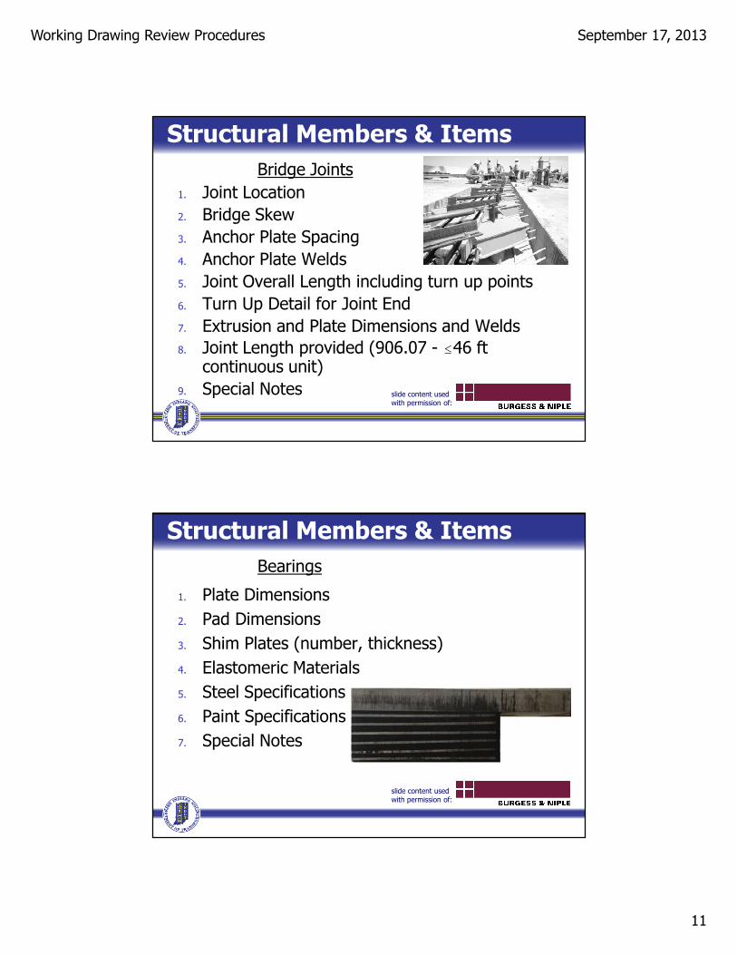
Structural Members & Items
1. Joint Location
2. Bridge Skew
3. Anchor Plate Spacing
4. Anchor Plate Welds
5. Joint Overall Length including turn up points
6. Turn Up Detail for Joint End
7. Extrusion and Plate Dimensions and Welds
8. Joint Length provided (906.07 - #46 ft continuous unit)
9. Special Notes
Bridge Joints
slide content used with permission of:
Structural Members & Items
Bearings
1. Plate Dimensions
2. Pad Dimensions
3. Shim Plates (number, thickness)
4. Elastomeric Materials
5. Steel Specifications
6. Paint Specifications
7. Special Notes
slide content used with permission of:

Working Drawing Review Procedures September 17, 2013
12
� These items are designed by the Contractor or their designated representative. Generally there are some basic design requirements in the Standard Specifications.
� Requires an Indiana PE,unless exempt (105.02 –
commercially availablepatented devices)
� Design calculations should be provided.
MSE Walls/Sound Barriers/PrecastConcrete Culverts/Traffic Items
MSE Walls/Sound Barriers/PrecastConcrete Culverts/Traffic Items
1. Check against plans, elevations and dimensions.
2. Print out controlling INDOT and project specific specifications and check against them
3. Verify proper geotechnical information is used in the design of the item
� Supplier suggestion include governing geotechnical requirements in the bid documents so they are easy for both the supplier and the reviewer to find and use
� If the geotechnical report is not part of the bid documents then it is not part of their
contractual obligation slide content used with permission of:

Working Drawing Review Procedures September 17, 2013
13
� For MSE walls, calculations should also be provided to INDOT Office of Geotechnical Engineering for a concurrent review.
� Some things to check for:
� Architectural finish & formliner style are incorporated, if applicable.
� Other unique elements are incorporated or have been accounted for.
� Minimum wall area has been provided.
MSE Walls
Submit a copy of drawings & calc’s to: [email protected]
Sound Barriers
� Some things to check for:
� Architectural finish & formliner style are incorporated, if applicable.
� Is it the proper type? (absorptive or reflective?)
� Post coating, galvanized or painted
� Other unique elements are incorporated or have been accounted for.
� Minimum wall area has been provided.

Working Drawing Review Procedures September 17, 2013
14
Precast Concrete Culverts
� Some things to check for:
� Are wingwalls & headwalls included? (714.04 & 723.02; IDM 203-2.06(01))
� Are coated reinforcing bars required? (IDM 203-2.06(02))
� Working drawings not required for box culverts listed in ASTM C 1577. Are required for all oversize boxes & all 3-sided.
� Minimum span/rise/waterway opening provided?
� These items are designed by the Contractor or their designated representative. Generally there are some basic design requirements in the Standard Specifications.
� Should be submitted to the PE/S.
Falsework and Temporary Bridge Drawings/Permanent Metal Deck Forms/Foundation Seals/Deck Pour Sequences/Stream Crossings and Work Bridges

Working Drawing Review Procedures September 17, 2013
15
� Requires an Indiana PE,
unless exempt (105.02 –
commercially availablepatented devices)
� Design calculations should be provided for falsework & permanent metal deck forms. They can be requested for other items.
Miscellaneous
� Such as:� Post tensioning plans, hand railing or pedestrian railing, etc…
� Submitted to the PE/S. The PE/S should work with the LPA & designer of record regarding review & approval process.

Working Drawing Review Procedures September 17, 2013
16
� Don’t review everything
� Don’t comment on things you shouldn’t
� Means and Methods of construction
� Providing the “Correct” dimension
� Make sure you have the most up to date plans.
� Avoid approving multiple versions of the same item.
� You are not the Quality control for the fabricator, things are supposed to be correct before they get to you
Review Considerations
slide content used with permission of:
� The drawing preparer is likely not an engineer if it’s a structural member shop drawing
� They may not be full time employees of the fabricator. Often fabricators will retain consultants to prepare their drawings.
� It is in the Contractor’s and your interest to get it done correctly and quickly.
Review Considerations
slide content used with permission of:
Working Drawing Review Procedures September 17, 2013
17
� When the review is complete, the reviewer should affix a review stamp to the plan sheets or design calculations, and should sign and date it.
� Each review firm should come up with the language they wish to put on their review stamp. Most common is a repeat of the specifications
“Drawing checked for design features only. Contractor is responsible for dimensions, accuracy, and fit of work.”
Review Considerations