Embed Size (px)
Citation preview
8/3/2019 Pdn.sciencedirect.com Science MiamiImageURL Cid=274151& User=452995& Pii=S1000936108600576& Check=y…
http://slidepdf.com/reader/full/pdnsciencedirectcom-science-miamiimageurl-cid274151-user452995-piis1000936108600576 1/7
Chinese
Journal of
Aeronautics Chinese Journal of Aeronautics 21(2008) 441-447
www.elsevier.com/locate/cja
Non-traditional Machining Techniques for Fabricating Metal
Aerospace Filters
Wang Weia,* , Zhu Dia, D. M. Allenb, H. J. A. Almondb aJiangsu Key Laboratory of Precision and Micro-manufacturing Technology, Nanjing University of Aeronautics and Astronautics,
Nanjing 210016, China
bSchool of Applied Sciences, Cranfield University, Bedford MK430AL, UK
Received 30 November 2007; accepted 21 January 2008
Abstract
Thanks to recent advances in manufacturing technology, aerospace system designers have many more options to fabri cate
high-quality, low-weight, high-capacity, cost-effective filters. Aside from traditional methods such as stamping, drilling and milling,
many new approaches have been widely used in f il ter-manufacturing practices on account of their increased processing abili ties. How-
ever, the restrictions on costs, the need for studying under stricter conditions such as in aggressive fluids, the complicity in design, the
workabil i ty of materials, and others have made it difficult to choose a satisfactory method from the newly developed processes, such as,
photochemical machining (PCM), photo electroforming (PEF) and laser beam machining (LBM) to produce small, inexpensive, light-
weight aerospace fi lters. This article appraises the technical and economical vi abili ty of PCM, PEF, and LBM to help engineers choose
the fittest approach to turn out aerospace filters.
Keywords: aerospace fi lter; photochemical machining; photo electroforming; laser beam machining
1 Introduction*
One of the main reasons for using non-tradi-
tional fabrication methods to fabricate filters, in
comparison with other methods such as stamping,
drilling and milling, is their capability to produce
micro holes economically and efficiently[1]. How-
ever, the correct choice of photochemical machining
(PCM), photo electroforming (PEF) or laser beam
machining (LBM) is still difficult because of the
technical and cost limitations[2], imposed by: com-plexity of design, process ability, surface quality,
precision required, cost-effectiveness of rival proc-
esses.
Moreover, the contamination capacity is a
*Corresponding author. Tel.: +86-25-84895718.
E-mail address : [email protected] item: Key National Natural Science Foundation of China
(50635040)
strong function of the total filter surface area and
initial porosity, which is also heavily dependent on
the fabrication methods[3].
In an attempt to evaluate non-traditional fabri-
cation methods that are now being used in this spe-
cific field, three kinds of commercial metal aero-
space filters are described, to demonstrate a choice
of suitable manufacturing techniques[4-5]. A flow-
diagram is provided, which will aid the selection
process for manufacturing aerospace filters withminimal cost.
2 Aerospace Filtration and Filters
2.1 Aerospace filtration
Aerospace filtration is generally classified as
either surface or depth filtration, depending on
where the particle retention takes place.

8/3/2019 Pdn.sciencedirect.com Science MiamiImageURL Cid=274151& User=452995& Pii=S1000936108600576& Check=y…
http://slidepdf.com/reader/full/pdnsciencedirectcom-science-miamiimageurl-cid274151-user452995-piis1000936108600576 2/7
· 442 · Wang Wei et al. / Chinese Journal of Aeronautics 21(2008) 441-447
Surface filtration is accomplished by the im-
pingement and retention of particles on a single sur-
face plane, namely, the outer surface of the filter
element. Filters that block contaminants on only one
surface, tend to inhibit the release of trapped con-taminants and lend themselves to cleaning by back-
flushing to a full y clean condition[7].
Conversely, depth filtration is the retention of
contaminant particles throughout the thickness of
the media. Consequently, it is possible that given
enough time, some of the contaminants may migrate
all the way through the media.
Generally speaking, the efficiency and cost-
effectiveness are the main problems of filtration.
The finer the filter, the more readily it becomes
clogged in the presence of coarser contaminants.
2.2 Aerospace filters
The propulsion, transmission and environment
systems are the main units in an aircraft. Hence
aerospace filter assemblies for fuel, lubrication and
hydraulic systems, oil scavenger filters, electronicequipment cooling filters, cabin air recirculation
filters and even space shuttle environmental system
filters are manufactured to demanding performance
and reliability standards[8-12].
Contamination levels in these cases are low for
obvious reasons, as shown in Table 1. These stan-
dards are commonly used in the UK, and give a
wide range of particle size distributions for different
aerospace appli cations. Other standards such as
DEF STAN 05-42, NAS 1638, and ISO 4406 arealso in common use throughout the world[13-15].
Table 1 Cleanliness standards for fuels contamination level classes for hydraulic systems in aerospace[6]
Satell it e Mi ssi le Sub-miniature servo-valves, someaircraft oils as new
Part icles per 100 mL by dirt contamination
Class 1-H Class 2-H Class 3-HSize range / m Class
(red)Tol
(green)
Distribu-tion/%
Class
(red)
Tol
(green)
Distribu-tion/%
Class
(red)
Tol
(green)
Distribu-tion/%
+100 7 2 0.015 7 2 0.001 5 7 2 0.000 7
50-100 15 4 0.044 15 4 0.003 0 15 5 0.001 6
25-50 94 27 0.279 104 29 0.023 0 133 40 0.014 0
15-25 290 64 0.836 370 71 0.083 0 529 160 0.057 0
10-15 701 180 2.086 1 810 518 0.406 0 3 677 1 128 0.401 05-10 1 617 415 4.812 22 320 6 377 5.019 0 50 050 15 617 5.473 0
1-5 30 882 7 918 91.899 420 000 120 000 94.461 0 860 606 260 780 94.053 0
Cum. total 33 606 8 610 / 444 626 127 001 / 915 017 277 282 /
Unfortunately, not all filtration in aerospace
applications can afford the cost and weight required
by normal filters. New filtration problems continue
to arise, such as the long-term operating life in ag-
gressive fluids, which necessitate the employment
of advanced manufacturing techniques.
3 Manufacturing Techniques
3.1 Traditional fabrication methods for metal
filters
The techniques for manufacturing metal filters
vary according to the composition of the filter mate-
rials. Woven wire cloth is often used for filtration. It
can be woven from nearly any metal ductile enough
to be drawn into wire form. The preferred materials
are phosphor bronze, stainless steel and Monel, as
shown in Fig.1.
(a) Plain dense weave (b) Twi ll ed Dutch weave
Fig.1 Woven wire cloths.
Mesh filter discs made of stainless steel woven
wire mesh are made rigid by sintering, a process
which produces fusion bonds at all contact points.
8/3/2019 Pdn.sciencedirect.com Science MiamiImageURL Cid=274151& User=452995& Pii=S1000936108600576& Check=y…
http://slidepdf.com/reader/full/pdnsciencedirectcom-science-miamiimageurl-cid274151-user452995-piis1000936108600576 3/7
Wang Wei et al. / Chinese Journal of Aeronautics 21(2008) 441-447 · 443 ·
Sintering maintains the uniformity of the original
weave and fixes the size and shape of the mesh.
Perforated metal plates are more rigid and can
be made stronger than woven wire cloth and so find
particular application in strainers, coarse filters andscreens. Fabrication methods include punching/
stamping, dril l ing and mil li ng.
3.2 Non-traditional fabrication methods
Unlike the machine shop methods such as
stamping, drilling and milling, many non-traditional
perforation methods leave the material free of in-
duced stress or deformation. Applications range
from heavy gauge effluent filtration to extremely
fine thin-gauge filters for liquids and gases. In many
cases, fabricated metal meshes provide better valueand performance than woven wire.
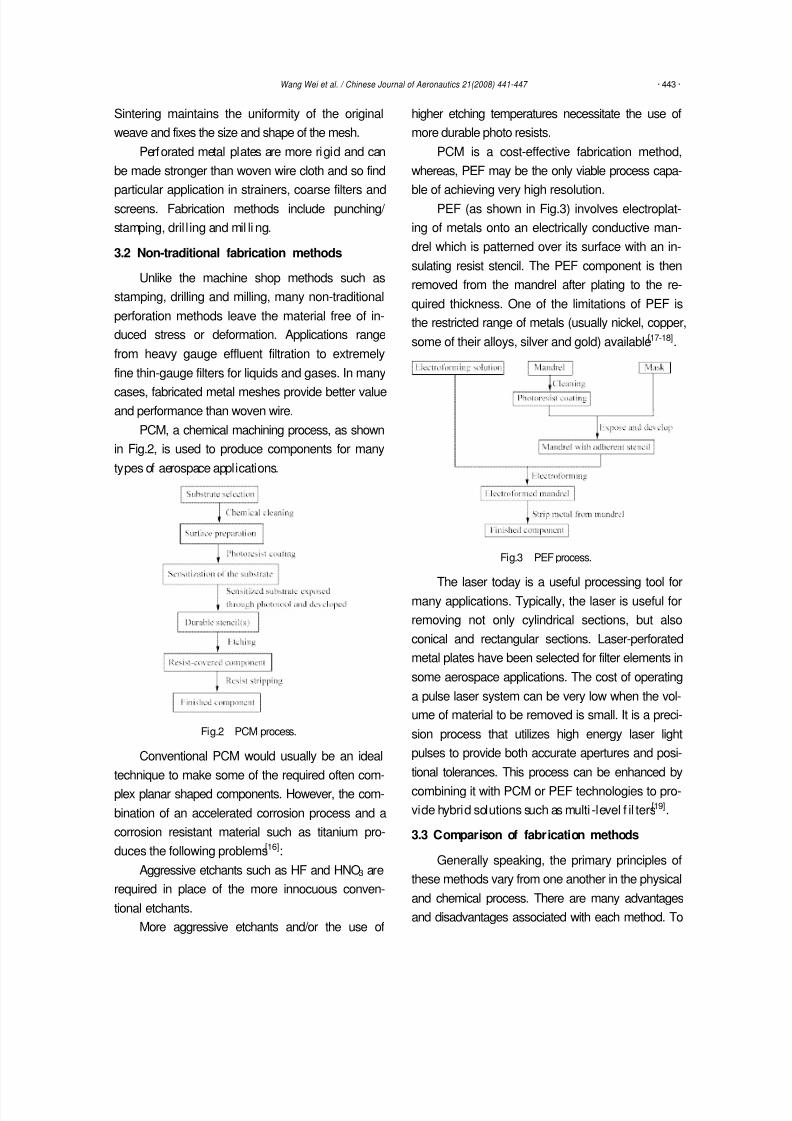
PCM, a chemical machining process, as shown
in Fig.2, is used to produce components for many
types of aerospace applications.
Fig.2 PCM process.
Conventional PCM would usually be an ideal
technique to make some of the required often com-
plex planar shaped components. However, the com-
bination of an accelerated corrosion process and a
corrosion resistant material such as titanium pro-
duces the following problems[16]:
Aggressive etchants such as HF and HNO3 are
required in place of the more innocuous conven-
tional etchants.
More aggressive etchants and/or the use of
higher etching temperatures necessitate the use of
more durable photo resists.
PCM is a cost-effective fabrication method,
whereas, PEF may be the only viable process capa-
ble of achieving very high resolution.PEF (as shown in Fig.3) involves electroplat-
ing of metals onto an electrically conductive man-
drel which is patterned over its surface with an in-
sulating resist stencil. The PEF component is then
removed from the mandrel after plating to the re-
quired thickness. One of the limitations of PEF is
the restricted range of metals (usually nickel, copper,
some of their alloys, silver and gold) available[17-18].
Fig.3 PEF process.
The laser today is a useful processing tool for
many applications. Typically, the laser is useful for
removing not only cylindrical sections, but also
conical and rectangular sections. Laser-perforated
metal plates have been selected for filter elements in
some aerospace applications. The cost of operating
a pulse laser system can be very low when the vol-
ume of material to be removed is small. It is a preci-
sion process that utilizes high energy laser light
pulses to provide both accurate apertures and posi-
tional tolerances. This process can be enhanced by
combining it with PCM or PEF technologies to pro-
vide hybrid solutions such as multi -level f il ters[19].
3.3 Comparison of fabrication methods
Generally speaking, the primary principles of
these methods vary from one another in the physical
and chemical process. There are many advantages
and disadvantages associated with each method. To
8/3/2019 Pdn.sciencedirect.com Science MiamiImageURL Cid=274151& User=452995& Pii=S1000936108600576& Check=y…
http://slidepdf.com/reader/full/pdnsciencedirectcom-science-miamiimageurl-cid274151-user452995-piis1000936108600576 4/7
· 444 · Wang Wei et al. / Chinese Journal of Aeronautics 21(2008) 441-447
define the technical differences in the fabrication
methods, traditional and non-traditional methods
have been compared in detail, as shown in Table 2.
However, to all designers, the chief concerns
are the materials processing ability, surface quality,accuracy and cost-effectiveness of rival processes,
which means that not only the technological, but
also the economic factors are definitely important.
For instance, PCM is a multi-stage process requiring
consumables such as cleaners, photo resists, etchant,
and strippers to be included in the cost which is
therefore relatively high. Although photo tooling
involves lower costs than preparing a punch and die,it is easy to understand that PCM is cheaper for low
volume production, whereas, stamping is cheaper
for high volume production.
Table 2 Technical comparison of fabrication methods
Minimum aperturesize (D: Depth)
Maximum mate-rial thickness(T: Thickness)
Material Process advantages Process disadvantages
Stamping
0.50T(low carbonsteel)
0.75T(high carbonsteel)
13 mm Nonbrittl e metals
Forming operations can becarried out whil st blanking
Fast
Long lead times
Deburring required
Drilling0.2T
(Normally)
Depends on drillsize Nonbrittle metals
Variable edge profil e
Fast
Deburring required
Drill fragilitySkilled operatives required
Milling0.1T
(Normally)10 mm Nonbrittl e metals
Thin slots
Relatively high aspect ratio
Deburring required
Mill fragility
Tool wear
PCM1.1T
(most metals)
1.5 mm
(6 mm for verylow resolution)
Al l metals (but varyin etchability)
Burr-f ree & stress-free
Characteristics of metal
material not altered
Variable edge profil e
Mul ti -stage process
Thickness limitation
PEF 0.1T-0.5T 2 mmUsually nickel,copper, sil ver or
gold
Very high resolution
Parts can be produced withunique multi -level features
Mul ti -stage process
Restricted range of metals
Slow
LBM 0.02T 10 mmAlmost all metals(except aluminum,
brass, etc.)
High aspect ratio
High precision
High efficiency
Heat affected zone
High facility cost
4 Aerospace Filters Manufactured by Non-
traditional Fabrication Methods
4.1 Advanced fluid filters
Etched disc filters, in stainless steel or titanium,
have been used as fluid filters in aerospace applica-
tions for a long time because they offer a number of
advantages over other filtering media such as wire
mesh or sintered materials
[20]
.To accomplish the disc design economically,
the discs are photochemically machined using a
negative working photo resist as the basic design
tool to differentiate between the areas to be etched
and the areas not to be etched. This etching process
is tightly controlled, using statistical process control
methods to ensure the geometric accuracy necessary
to meet the performance requirements. The fabrica-
tion process is completed by stacking the individual
chemically etched discs, to make up the filter ele-
ment assembly.
Recent advances in etched disc filtration tech-
nology combine two distinct design and manufac-
turing features. The new design concept has pro-
duced a filter with a more efficient pressure drop
and dirt capacity holding characteristics. Addition-
ally, the new process of diffusion bonding hasminimized the manual assembly of the filters with
substantial improvement in the efficiency and pro-
ductivity of the assembly process.
Fig.4 shows the new, efficient titanium disc
configuration. The physical size in terms of I.D.
(Ø31.29 mm) and O.D. (Ø36.83 mm) is reduced for
the same flow area as the traditional etched disc
design. These high efficiency discs are approxi-

8/3/2019 Pdn.sciencedirect.com Science MiamiImageURL Cid=274151& User=452995& Pii=S1000936108600576& Check=y…
http://slidepdf.com/reader/full/pdnsciencedirectcom-science-miamiimageurl-cid274151-user452995-piis1000936108600576 5/7
Wang Wei et al. / Chinese Journal of Aeronautics 21(2008) 441-447 · 445 ·
mately 25 m thick (compared with 50 to 80 m
thick in the case of traditional discs). Therefore,
more discs can be stacked per mm of filter length
(approx. 40 pcs). In fact, the open area in this new,
high efficiency, etched disc design is about 50%, ascompared to only 15%-20% in the traditional de-
sign[21].
(a) Tradit ional etched disc and fi l ter assembly
(b) Hi gh eff ici ency etched disc and fi lter assembly
Fig.4 Titanium disc filter and etched disc.
(Courtesy of Vacco Industries, CA, USA) [22]
Therefore, both of these new features serve to
reduce the total weight and volume envelope re-
quired for a specific design parameter. Traditionally,
filters with similar flow/pressure drop requirements
weighed approximately 990 g; the high efficiency
filter weighs only 86 g. This research and develop-
ment study has therefore resulted in a new genera-
tion of optimized etched disc filters for space appli-
cations[22].
4.2 Ultra fine micro filters
PEF is a combination of photo resist imaging
and electroforming. Material thickness can be as
thin as 3-4 m. Dimension tolerances are generally
±10 m or better. Positional tolerances are normally
±(1-2) m and through holes are as small as 2-3 m.Parts can be produced with unique multi-level fea-
tures, as shown in Fig.5.
If a design can be drawn in a 2D CAD file, the
chances are good that it can be electroformed.
Therefore, parts and components are produced for
many markets, including masking, sieving, avionics,
filtration, medical devices, electronics, scientific
controls and much more[23].
(a) Overgrown (b) Mul ti -level
Fig.5 Unique structures in nickel mesh.
(Courtesy of Tecan Ltd., Weymouth, UK)
Recently, LIGA or LIGA-like technology has
been introduced to the micro fabrication area, espe-
cially for non-silicon materials[24]. The high aspect
ratio of microstructures can be realized with a high
resolution photo resist (e.g. SU-8) for micron orsub-micron features, which can be used to fabricate
micro filters for power and propulsion systems in
aerospace applications, such as, micro air vehicles
(MAVs) and future satell ites.
4.3 Titanium propellant filters
The long-term operating life of a propellant
filter in aggressive fluids is a key constraint in the
design of this product, as only a few materials are
compatible with such fluids over long periods. The
use of titanium in contact wi th these fluids, typicallymono methyl hydrazine (MMH) and nitrogen tetr-
oxide (NTO), is a long-term, flight-validated solu-
tion selected for the development of the propellant
filter in Europe[5].
However, because of the poor ductility charac-
teristics of titanium and irregularity in diameter of
the wire, titanium screen mesh and coiled wire
technologies are not suitable for this appli cation.
It is possible to manufacture a filtering medium
using a titanium plate. The filtering characteristicsare provided by the definition of the perforations.
Absolute filtration rate is directly linked to the di-
mensions of the holes. Other characteristics (pres-
sure drop and dirt holding capacity) depend on the
global transparency (ratio between the open area
and the total area of the perforated plates). It is nec-
essary for this application to use a high accuracy
process such as LBM.
8/3/2019 Pdn.sciencedirect.com Science MiamiImageURL Cid=274151& User=452995& Pii=S1000936108600576& Check=y…
http://slidepdf.com/reader/full/pdnsciencedirectcom-science-miamiimageurl-cid274151-user452995-piis1000936108600576 6/7
· 446 · Wang Wei et al. / Chinese Journal of Aeronautics 21(2008) 441-447
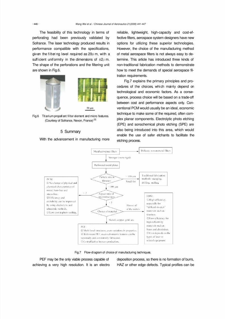
The feasibility of this technology in terms of
perforating had been previously validated by
Sofrance. The laser technology produced results in
performance compatible with the specifications,
given the filtering level required as 20 m, with asuff icient uniformity in the dimensions of ±2 m.
The shape of the perforations and the filtering unit
are shown in Fig.6.
Fig.6 Titanium propell ant fi lter element and micro features.
(Courtesy of Sofrance, Nexon, France) [5]
5 Summary
With the advancement in manufacturing more
reliable, lightweight, high-capacity and cost-ef-
fective filters, aerospace system designers have new
options for utilizing these superior technologies.
However, the choice of the manufacturing method
of metal aerospace filters is not always easy to de-termine. This article has introduced three kinds of
non-traditional fabrication methods to demonstrate
how to meet the demands of special aerospace fil-
tration requirements.
Fig.7 explains the primary principles and pro-
cedures of the choices, whi ch mainly depend on
technological and economic factors. As a conse-
quence, process choice will be based on a trade-off
between cost and performance aspects only. Con-
ventional PCM would usually be an ideal, economic
technique to make some of the required, often com-
plex planar components. Electrolytic photo etching
(EPE) and sonochemical photo etching (SPE) are
also being introduced into this area, which would
enable the use of safer etchants to facilitate the
etching process.
Fig.7 Flow-diagram of choice of manufacturing techniques.
PEF may be the only viable process capable of
achieving a very high resolution. It is an electro
deposition process, so there is no formation of burrs,
HAZ or other edge defects. Typical profiles can be

8/3/2019 Pdn.sciencedirect.com Science MiamiImageURL Cid=274151& User=452995& Pii=S1000936108600576& Check=y…
http://slidepdf.com/reader/full/pdnsciencedirectcom-science-miamiimageurl-cid274151-user452995-piis1000936108600576 7/7
Wang Wei et al. / Chinese Journal of Aeronautics 21(2008) 441-447 · 447 ·
overgrown and stepped multi-level, as seen in Fig.5.
One of the limitations of PEF is the restricted range
of metals.
LBM is a direct CAD-to-production process
with no photo tooling required. This enables a rapidturnaround, with delivery of certain products on the
same day. Laser-perforated metal plate is the se-
lected technology for filter elements in aerospace
applications. It is a precision process that utilizes
high energy laser light pulses to provide both accu-
rate apertures and positional tolerances.
Acknowledgements
The authors wish to acknowledge Vacco Indus-
tries, South El Monte, CA, USA, Tecan Ltd., Wey-
mouth, Dorset, UK and Sofrance, Nexon, France,for their contributions to this article.
Many thanks to Nanjing University of Aero-
nautics and Astronautics for permission to spend a
sabbatical year at Cranfield University working with
Professor David Allen and Dr Heather Almond on
aspects of etching technology, and also China
Scholarship Council for the funding to do so.
References
[1] Sommer C. Non-traditional machining handbook. Houston, Tex:
Advance Publishing Inc, 2000.
[2] Fine Wire Mesh for Filter Elements. SAE Standard AI R888, 1997.
[3] Tretyakov A F. Manufacturing the filters with preset properties.
Metallurg 1995; 7: 24-25.
[4] Moshirpour A, Hoppe R. An integral diffusion-bonded, etched
disc propellant f il ter. AIAA-2000-3636, 2000.
[5] Garnero P, Jamin A , Lecardonne L. B i-propellant propulsion
system improvement for telecommunication satellites. AIAA-
2004-4211, 2004.
[6] Eaton-Dikeman C. Filters and filtration handbook. 4th ed. Oxford:
Elsevier Advanced Technology, 1997; 843.
[7] Filter element cleaning methods. SAE Standard AIR787, 2003.
[8] Morvan P. Filters for the aerospace industry. News from Prospace,
2000; 40- 41.
[9] Madhavan P. Advances in aircraft transmission lubricant filtration
technology. AIAA -1988-2984, 1988.
[10] Trego L. Hydraulic system purification. Aerospace Engineering
1997; 17: 31-34.
[11] Jen C. A high capacity advanced fuel filtration system. AD-
A384193, MSI-TR-8002, 2000.
[12] Multi-phase method for evaluating filtration performance of fine
lube filter elements utilized in aerospace power and propulsion
lubrication systems. SAE Standard ARP5454, 2003.
[13] Measuri ng aircraft gas turbine engine fi ne fuel f il ter element
performance. SAE Standard ARP1827, 2003.
[14] Holcomb L C. Proposed ASHRA E cabin air quali ty standard. 161P,
1999.
[15] Dyer K, Yankura G, Acosta J. Low mass components for Mars
ascent propulsion. Journal of Propulsion and Power 2001; 17(4):
758-761.
[16] Allen D M. The principles and practice of photochemical machin-
ing and photoetching. Bristol: IOP, 1986.
[17] Thomson J R. Electroforming. London: A. & C. Black, 2004.
[18] Zhu D, Zhang G B, Zhu F X. Manufacture of micro gauzes by
precision electroforming. Aerospace Precision Manufacturing
Technology 1996; 32: 22-23. [i n Chinese]
[19] Pajak P T. Laser machini ng: theory and practice. New York:
Springer-Verlag, 1991.
[20] Allen D M, Talib T N. Manufacture of stainless steel edge filters:
an application of electrolyt ic photo polishing. Precision Engineer-
ing 1983; 5: 57-59.
[21] Gonzalez A E. Etched disc wi th crosshatch pattern. U.S. Patent,
5711877, 1998.
[22] Barnett J M, Otsap B. Diffusion bonded, high efficiency etched
disc filters. AIAA-1999-2328, 1999.
[23] Electrof orming targets the very small . Metal Powder Report 2003;
58(7-8): 6-6(1).
[24] Hart T, Watson A. Electroforming. Metal Finishing 2001; 99:
387-398.
Biography:
Wang Wei Born in 1973, received the Ph.D. degree in
mechanical engineering from Nanjing University of Aero-
nautics and Astronautics in 2000. His main research interests
are micro fabrication and non-traditional machining tech-
nologies.
E-mail: [email protected]