Embed Size (px)
Citation preview

PEAPODTest Readiness Review
Pneumatically Energized Auto-throttled Pump Operated for a Developmental Upperstage
Customer: Special Aerospace ServicesChris Webber and Tim Bulk 1

• Project Overview• Schedule• Test Readiness• Budget
Overview
BudgetTest ReadinessOverview Schedule 2

Project Overview
3

•Design, manufacture, and test a pneumatically powered pump system for use on an upper stage rocket engine or lander.• Proof of concept pump system for hypergolic
propellants• 10%-100% throttleability• Pneumatically powered
Project Motivation
4BudgetTest ReadinessOverview Schedule
CONOPS
5BudgetTest ReadinessOverview Schedule

MotorMotorDriver
Power
120WPowerSupply
120ACwallpower
Tachometer
PumpManualPressureRegulator
SolenoidValve
WaterSupply
HeliumTank
ReliefValve Sink
ManualBallValve
ManualPressureRegulator
SolenoidValve
ReliefValve
ElectronicPressureRegulator
DriveSystem Muffler
1600WPowerSupply
MotorMotorDriver
ElectronicPressureRegulator
FaradayCageDAQ2
SignalConditioning
PressureTransducer
Thermocouple ThermocouplePressureTransducer
PressureTransducer
28V
28V
DAQ1Power
Distribution
24V 28V28V
24V
UserComputer
600W
600W
Key
Provided
Purchased
Manufactured
AnalogSignal
DigitalSignal
ElectricalPower
MechanicalPower
Functional Block Diagram
6
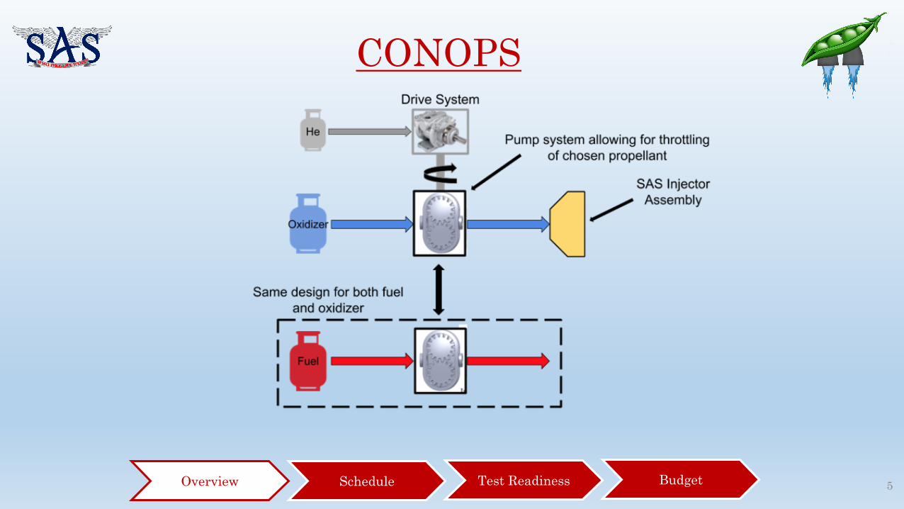
Baseline Design
7
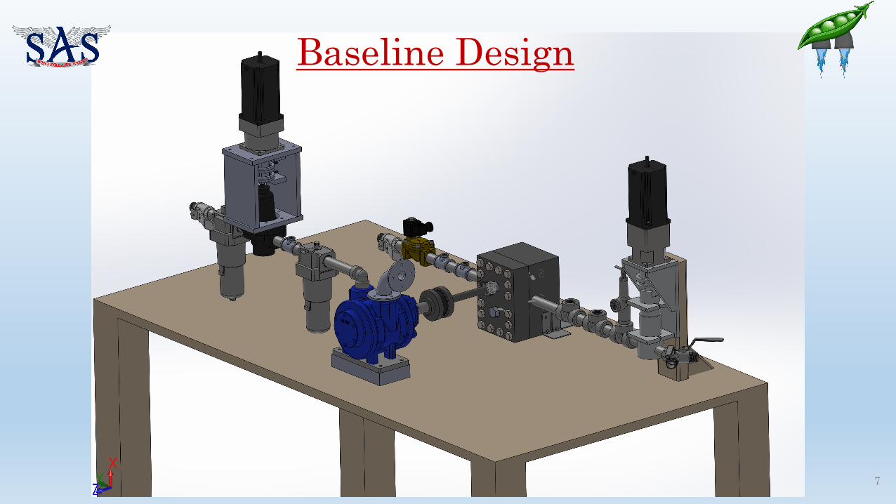
Baseline Design
8
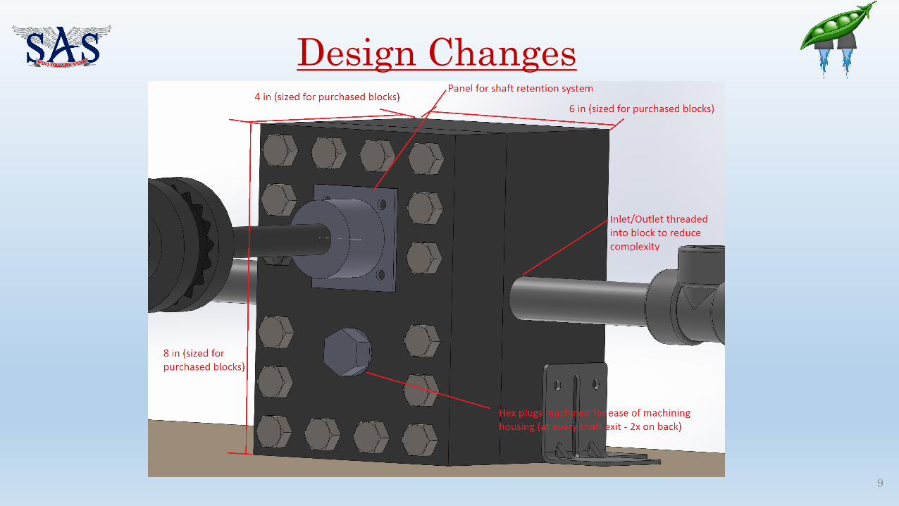
Design Changes
9

Design Changes – Air Motor Pressure Regulator
10
Constructed from a manual regulator and stepper motor:
Manual Regulator:• 400 scfm flowrate (360 required)• 0 psi to 120 psi (105 psi required)• 12 turns for 0 psi to 105 psi• 8 N-m max. adjustment torque
Stepper Motor (HT34-487) w/Gearbox• 2.2rev/s max. rotation rate (0.6 rev/s
required)• 25 N-m min. torque (8 N-m
required)

Design Changes – Back-Pressure Regulator
11
Constructed from a manual back-pressure regulator and
stepper motor:
Manual Back-Pressure Regulator:• 200 lpm flowrate (84 required)• 75 psi to 750 psi (full range req.)• 11 turns for 75 psi to 750 psi• 15N-m max. adjustment torque
Stepper Motor (HT34-487) w/Gearbox• 4 rev/s max. rotation rate (2.2 rev/s
required)• 25 N-m min. torque @ 2.2 rev/s (15
N-m required)

Critical Project Elements
11
CPEs from CDR RationaleDevelop a functioning pump Manufacturing of the pump is in progress, but
assembly and operation of the pump could pose a time risk.
Meet efficiency requirement of 75% Control and design of the pump could cause the pump to achieve a lower efficiency.
Correct acquisition of pressure, RPM, and mass flow rate Have yet to acquire a measurement on flow rate, which is needed for Level 1 Success.
Developing throttling capabilities (10-100%) Throttling the air motor using a stepper motorattached to a regulator creates unforeseen mechanical and control loop challenges.
Safe operation of pump and drive system Operating a pump with high pressures using digital control can present a multitude of problems towards safety.
Budgetary restrictions A multitude of parts to purchase
BudgetTest ReadinessOverview Schedule

Levels of SuccessLevel Performance Success
1 • 750 ± 15 psi outlet pressure• Structural FOS 2.5• 120 seconds of operation• 75% efficiency of pump at full throttle
2 • 10-100% throttleability• 0-100% throttle in 2 seconds• All level 1 requirements
3 • 0-100% throttle in 1 second• All level 1 and 2 requirements• Hypergolic Compatible
13
KeyOn Track
CompletedConcerned
Will Not Meet
BudgetTest ReadinessOverview Schedule

Schedule
14
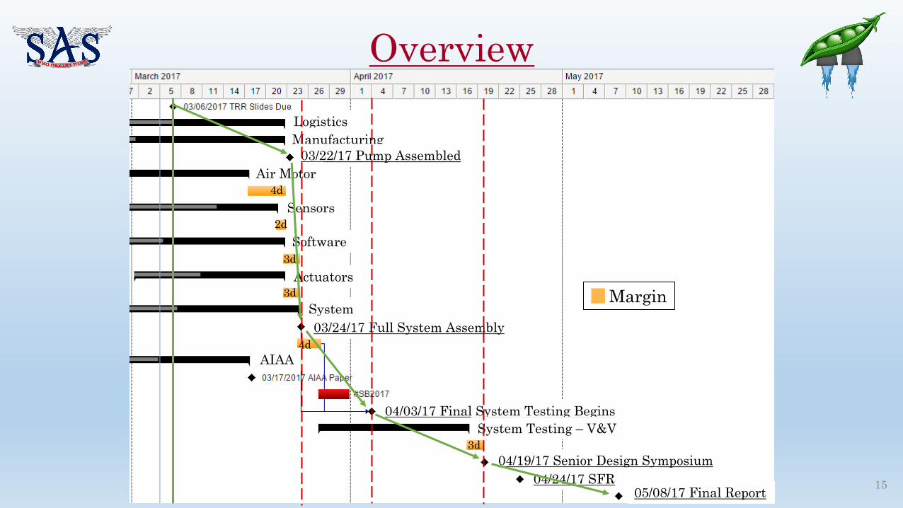
Overview
Margin
4d
2d
3d
3d
4d
3d
15
LogisticsManufacturing
Sensors
Software
Actuators
System
03/22/17 Pump Assembled
03/24/17 Full System Assembly
04/03/17 Final System Testing BeginsSystem Testing – V&V
Air Motor
AIAA
04/19/17 Senior Design Symposium04/24/17 SFR
05/08/17 Final Report

Manufacturing
BudgetTest ReadinessOverview Schedule 16

Testing
BudgetTest ReadinessOverview Schedule
Margin
4d
2d
17

Testing
BudgetTest ReadinessOverview Schedule
Margin3d
3d
18

Testing
Margin
4d
3d
19

Largest ConcernsHousing manufacturing is a slow process
Control loop design may take longer than expected and already have encountered some DAQ issuesWaiting for the arrival of the drivers. Possibility of integration and control problems with the regulators Having enough time to
troubleshoot and verify our requirements
20

Test Readiness
21
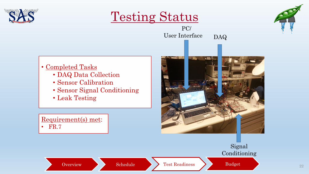
Testing Status
Requirement(s) met:• FR.7
• Completed Tasks• DAQ Data Collection• Sensor Calibration• Sensor Signal Conditioning• Leak Testing
PC/ User Interface DAQ
Signal Conditioning
BudgetTest ReadinessOverview Schedule 22

Subsystem Test Plan Overview
Margin = 14 days
23

Subsystem Test Plan Overview
Sensor Q&C and breadboard
design
Solenoid Testing
Feb. 6-28
DAQ Sensor Integration
Control Logic Development
Feb. 28 – Mar. 6
Air Motor Testing
Mar. 6-12 Mar. 12-20
DAQ GUIRegulator Testing
Pump Assembly
Stepper Motor Test
Mar. 20-22
Air Motor Throttling
BudgetTest ReadinessOverview Schedule 24
Iteration of control algorithm

System CAD Model
25

Test Setup:
Test Rationale: Relate regulator opening to downstream pressure through data collection. Use results to calibrate downstream pressure to regulator thread engagement.
Equipment required:• 1” Manual Ball Valve• 1” Electric Solenoid Valve• 2x Pressure Transducer (1/4”NPT fitted in Tee)• 1” Manual Pressure Regulator• 1” Venting Cap• 1” Piping
Facilities required:• Air compressor providing 100PSI provided in
Projects Room
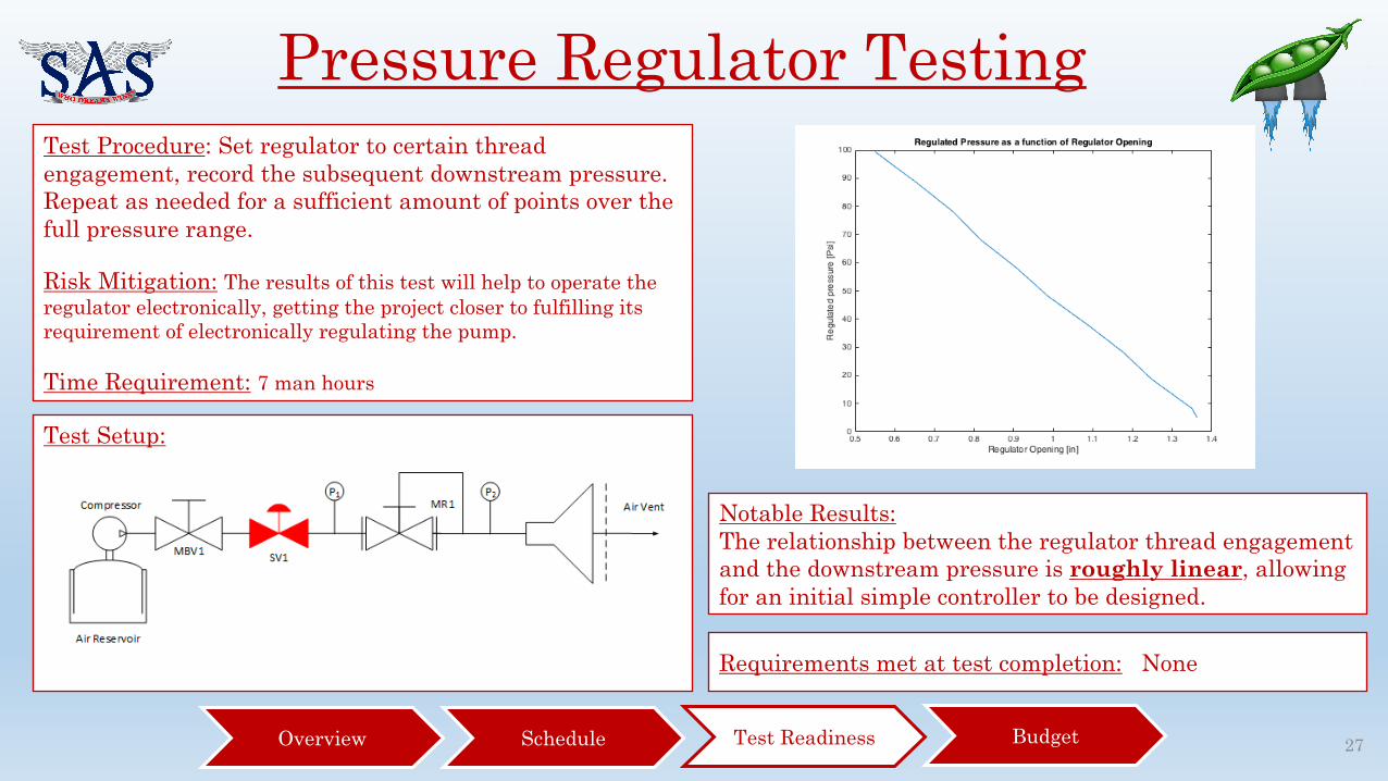
Pressure Regulator Testing
26
MBV Manual Ball Valve
SV Solenoid Valve
P Pressure Transducer
MR Manual Regulator
Test Setup:
Test Procedure: Set regulator to certain thread engagement, record the subsequent downstream pressure. Repeat as needed for a sufficient amount of points over the full pressure range.
Risk Mitigation: The results of this test will help to operate the regulator electronically, getting the project closer to fulfilling its requirement of electronically regulating the pump.
Time Requirement: 7 man hours
Notable Results:The relationship between the regulator thread engagement and the downstream pressure is roughly linear, allowing for an initial simple controller to be designed.
Pressure Regulator Testing
Requirements met at test completion: None
BudgetTest ReadinessOverview Schedule 27

Test Setup:
Air Motor TestingTest Rationale: Determine the operational throttle range of the motor. Quantification of motor vibrations.
Equipment required:• 1” Manual Ball Valve• 1” Electric Solenoid Valve• 125PSI Relief Valve (1/4”NPT fitted in Tee)• 1” Air Filter• Pressure Transducer (1/4”NPT fitted in Tee)• 1” Manual Pressure Regulator• 1” Air Lubricator• Air Motor with muffler mounted on exhaust• Tachometer• Shaft Torque Device• 1” Piping
Facilities required:• Air compressor providing 100PSI Air @45CFM,
provided on East Campus
Test Setup:
BudgetTest ReadinessOverview Schedule 28
MBV Manual Ball Valve
SV Solenoid Valve
RV Relief Valve
P Pressure Transducer
MR Manual Regulator
F Air Filter
LB Air Lubricator
TM Tachometer

Air Motor Testing
Test Setup:Test Procedure:Regulator is set to a known pressure (starting at 10PSI), the system is activated. The resulting RPM of the drive shaft is recorded. The test is run for a the full range of pressures 0-100PSI.
Risk Mitigation: The results of this test will verify that the motor can attain the full throttle range of 10-100% throttle-ability. This test will also quantify expected vibrations the motor will induce on the test assembly
Time Requirement: 20 man hoursRequirements met at test completion:• FR2 – Pump is throttleable
BudgetTest ReadinessOverview Schedule 29

Stepper Motor Testing – Phase 1Test Rationale: Determined motor can be controlled through LabVIEW. Quantify accuracy of control system and slew rates
Equipment required:• Computer• Data Acquisition (DAQ)• Stepper Motor• Motor Driver• 1600W power supply
Facilities required:• Projects room
Test Setup:
BudgetTest ReadinessOverview Schedule 30
Stepper Motor Testing – Phase 1
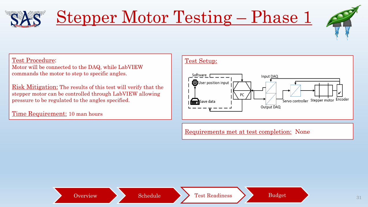
Test Setup:Test Procedure:Motor will be connected to the DAQ, while LabVIEW commands the motor to step to specific angles.
Risk Mitigation: The results of this test will verify that the stepper motor can be controlled through LabVIEW allowing pressure to be regulated to the angles specified.
Time Requirement: 10 man hours
Requirements met at test completion: None
BudgetTest ReadinessOverview Schedule 31

Stepper Motor Testing – Phase 2
Test Setup:Test Procedure:Motor will be connected to the DAQ, while in LabVIEW the command the motor to step at specific angles. The corresponding downstream pressure is recorded. The test is then iterated through a series of pressure settings
Risk Mitigation: The results of this test will verify that the stepper motor can be controlled through LabVIEW allowing pressure to be regulated electronically. This allows for the development of the feedback control with the downstream pressure transducer.
Time Requirement: 10 man hours
Requirements met at test completion: None
BudgetTest ReadinessOverview Schedule 32
MBV Manual Ball Valve
SV Solenoid Valve
P Pressure Transducer
EP Electronic Pressure Regulator

Test Setup:Test Setup:
Test Rationale: Verify that acquired stepper motor operates as expected. Verify that control algorithms and driver correctly actuate motor to desired positions. Quantify accuracy of control system and slew rates
Equipment required:• 1” Manual Ball Valve• 1” Electric Solenoid Valve• 125PSI Relief Valve (1/4”NPT fitted in Tee)• 1” Air Filter• Pressure Transducer (1/4”NPT fitted in Tee)• 1” Manual Pressure Regulator mounted
with stepper motor• 1” Air Lubricator• Air Motor with muffler mounted on exhaust• Tachometer• Shaft Torque Device • 1” Piping
Facilities required:• Air compressor providing
100PSI Air @45CFM, provided on East Campus
Air Motor Throttling
BudgetTest ReadinessOverview Schedule 33
MBV Manual Ball Valve
SV Solenoid Valve
RV Relief Valve
P Pressure Transducer
BPR Back Pressure Regulator
EP Electronic Pressure Regulator
F Air Filter
LB Air Lubricator
TM Tachometer

Test Setup:Test Procedure:The DAQ system is loaded with a desired throttle profile. The DAQ now starts up the test by setting the motor to 10% throttle. The motor is then ran through a throttle profile.
Risk Mitigation: The results of this test will verify that the stepper motor can actuate the regulator through the full range of 10-100% to guarantee electronic throttle-ability. This test will also quantify the slew rate of this control system.
Time Requirement: 15 man hours
Requirements met at test completion:• FR2 - Pump is electronically throttleable• FR4 - Pump system can run throttle profile
Air Motor Throttling
BudgetTest ReadinessOverview Schedule 34
Final Test Plan Overview
BudgetTest ReadinessOverview Schedule 35
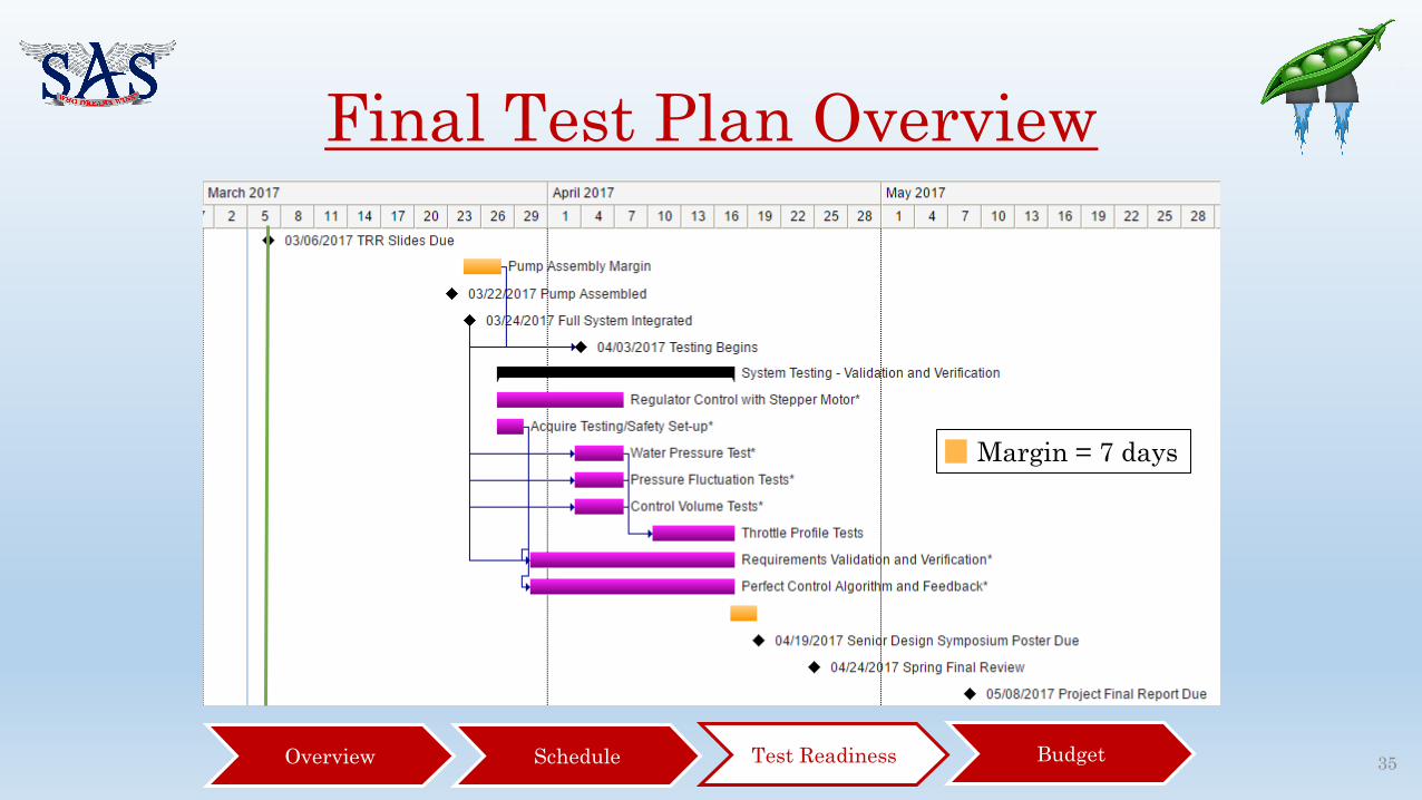
Margin = 7 days

Final Test Plan OverviewMar. 21 -23
Pump Assembly
Apr. 3 - 7
Outlet Pressure Testing
Apr. 7 - 17
Pressure Fluctuation
Testing
Throttle Profile Testing
K-Bottle Testing
Iteration of control algorithm
Mass Flow Rate Testing
BudgetTest ReadinessOverview Schedule 36

Test Setup:
Test Rationale: Verify that after full assembly the pump outputs the expected amount of water for a certain throttle setting.
Equipment required:• Complete Assembly of all systems, operational
DAQ and control components
Facilities required:• Air compressor providing 100PSI Air @45CFM,
provided on East Campus
Mass Flow Rate Testing
BudgetTest ReadinessOverview Schedule 37
MBV Manual Ball Valve
SV Solenoid Valve
RV Relief Valve
P Pressure Transducer
T Thermocouple
MR Manual Regulator
BPR Back Pressure Regulator
EP Electronic Pressure Regulator
F Air Filter
LB Air Lubricator
TM Tachometer

Test Setup:
Test Procedure:The DAQ system is loaded with a desired throttle setting (constant). The pump is set to run, the flow is switched to the control volume for a certain amount of time and then switched back to the regular sink.
Risk Mitigation: The results of this test will verify that the system meets design expectations, that is meeting an output flow rate of 1.4L/s
Time Requirement: 20 man hours
Requirements met at test completion:• DR2.1 - Pump operates at 1.4L/s at full throttle
Mass Flow Rate Testing
BudgetTest ReadinessOverview Schedule 38

Test Setup:
Test Rationale: Verify that after full assembly the pump output flow has minimal pressure fluctuation.
Equipment required:• Complete Assembly of all systems, operational
DAQ and control components
Facilities required:• Air compressor providing 100PSI Air @45CFM,
provided on East Campus
Pressure Fluctuation Testing
39
MBV Manual Ball Valve
SV Solenoid Valve
RV Relief Valve
P Pressure Transducer
T Thermocouple
MR Manual Regulator
BPR Back Pressure Regulator
EP Electronic Pressure Regulator
F Air Filter
LB Air Lubricator
TM Tachometer
BudgetTest ReadinessOverview Schedule

Test Setup:Test Procedure:The DAQ system is loaded with a desired throttle setting (constant). The pump is set to run, the output flow pressure is measured and recorded.
Risk Mitigation: The results of this test will verify that the pump meets design expectations, that is of having pressure fluctuations no greater than 15PSI.Time Requirement: 5 man hours
Requirements met at test completion:• DR2.3 - Pump operates with pressure fluctuations
less than 15PSI
Pressure Fluctuation Testing
40BudgetTest ReadinessOverview Schedule

Test Setup:
Test Rationale: Verify that after full assembly the pump system can operate using a Helium K-Bottle to run the motor.
Equipment required:• Complete Assembly of all systems, operational
DAQ and control components
Facilities required:• Water Source• Helium K-Bottle
K-Bottle Testing
41
MBV Manual Ball Valve
SV Solenoid Valve
RV Relief Valve
P Pressure Transducer
T Thermocouple
MR Manual Regulator
BPR Back Pressure Regulator
EP Electronic Pressure Regulator
F Air Filter
LB Air Lubricator
TM Tachometer
BudgetTest ReadinessOverview Schedule

Test Setup:
Test Procedure:The pump system is setup as it normally would except that instead of using compressed air, the motor system uses a helium k-bottle.
Risk Mitigation: The results of this test will verify that the pump meets design expectations, that is of being able to run off of a helium k-bottleTime Requirement: 10 man hours Requirements met at test completion:
• DR1.1 - Pump operates with a Helium K-Bottle
K-Bottle Testing
42BudgetTest ReadinessOverview Schedule
Test Setup:
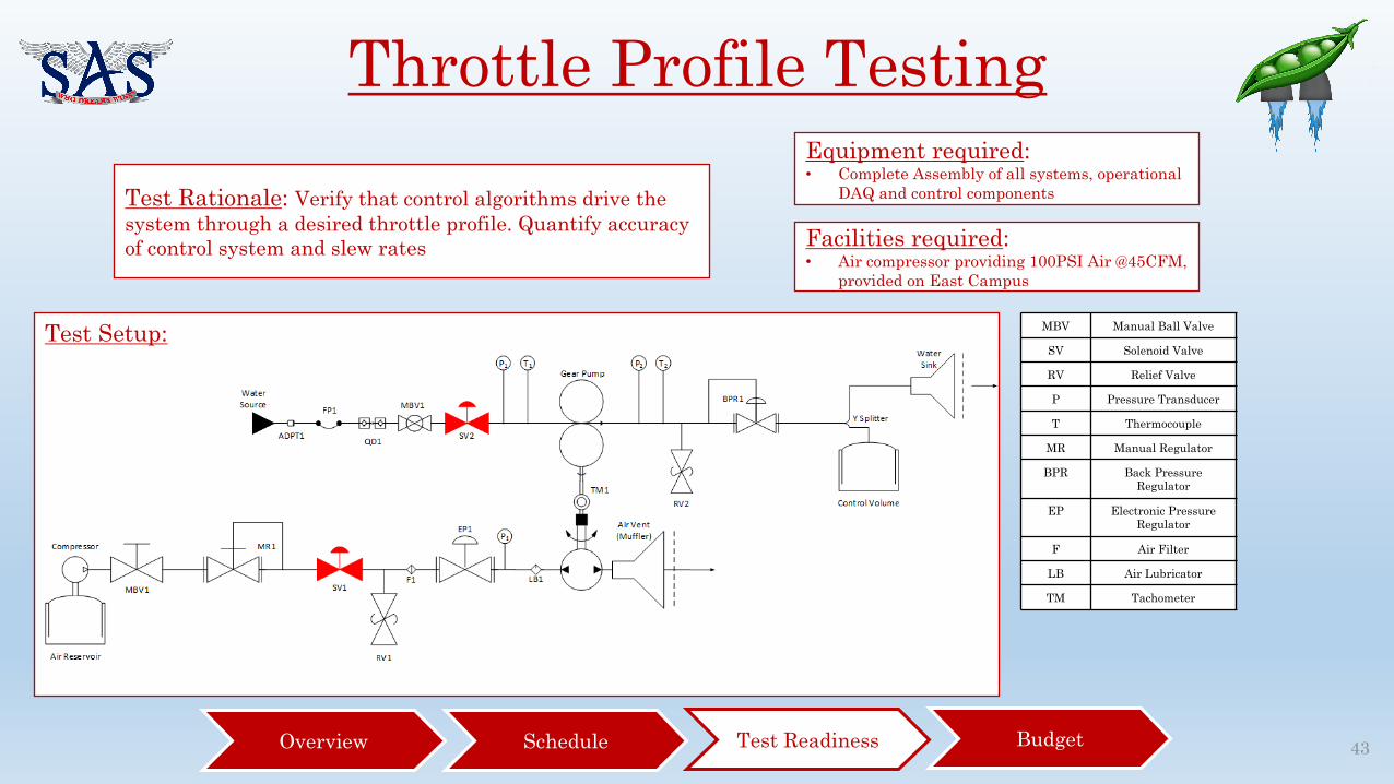
Test Rationale: Verify that control algorithms drive the system through a desired throttle profile. Quantify accuracy of control system and slew rates
Equipment required:• Complete Assembly of all systems, operational
DAQ and control components
Facilities required:• Air compressor providing 100PSI Air @45CFM,
provided on East Campus
Throttle Profile Testing
43
MBV Manual Ball Valve
SV Solenoid Valve
RV Relief Valve
P Pressure Transducer
T Thermocouple
MR Manual Regulator
BPR Back Pressure Regulator
EP Electronic Pressure Regulator
F Air Filter
LB Air Lubricator
TM Tachometer
BudgetTest ReadinessOverview Schedule

Test Setup:Test Procedure:The DAQ system is loaded with a desired throttle setting (constant). The pump is set to run, the full system operation is monitored and recorded.
Risk Mitigation: The results of this test will verify that the pump system can correctly run a throttle profile. Successfully doing this would demonstrate the completeness of the project.
Time Requirement: 15 man hours Requirements met at test completion:• All requirements are met at this point
Throttle Profile Testing
44BudgetTest ReadinessOverview Schedule

Test Setup:
Test Rationale: Verify that acquired stepper motor operates as expected. Verify that control algorithms and driver correctly actuate motor to desired positions. Quantify accuracy of control system, slew rates and torque.
Equipment required:• Pressure Transducer (1/4”NPT fitted in Tee)• 1” Manual Pressure Regulator mounted with
stepper motor• Computer• Data Acquisition DAQ• Motor Driver• Stepper Motor• Power Supply• 1” Piping
Facilities required:• Projects room
Control Algorithm Iteration
BudgetTest ReadinessOverview Schedule 45
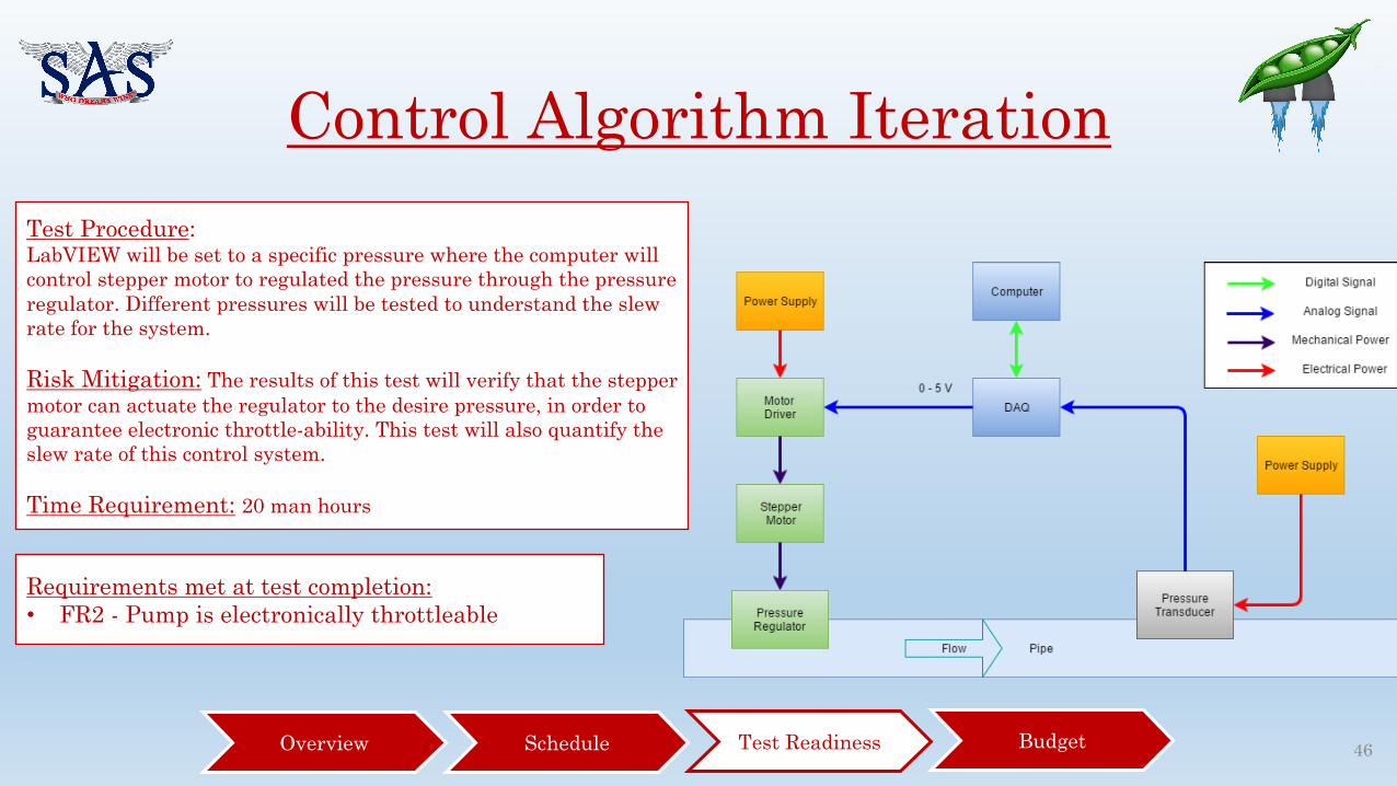
Control Algorithm IterationTest Procedure:LabVIEW will be set to a specific pressure where the computer will control stepper motor to regulated the pressure through the pressure regulator. Different pressures will be tested to understand the slew rate for the system.
Risk Mitigation: The results of this test will verify that the stepper motor can actuate the regulator to the desire pressure, in order to guarantee electronic throttle-ability. This test will also quantify the slew rate of this control system.
Time Requirement: 20 man hours
Requirements met at test completion:• FR2 - Pump is electronically throttleable
BudgetTest ReadinessOverview Schedule 46

Budget
47

Budget Statistics and Progress
• 85.89% of Parts purchased (by dollar value)• $1173.10 of Margin!
*See backup slides for full itemized budget
BudgetTest ReadinessOverview Schedule 48

Budget: Parts left to buy
Left to buy: $962.85
BudgetTest ReadinessOverview Schedule 49

Questions?
50

Backup
51

DAQ Input Testing
52

System Tests
• Goals• Determinedatavariance andsystem(non-sensor)error• Qualitatively verify alldatalinks work
• Equipment• DAQ• PC(withLabVIEW)• Thermocouples• Pressuretransducers• Tachometer• Solenoidvalves• DCpowersupply
53
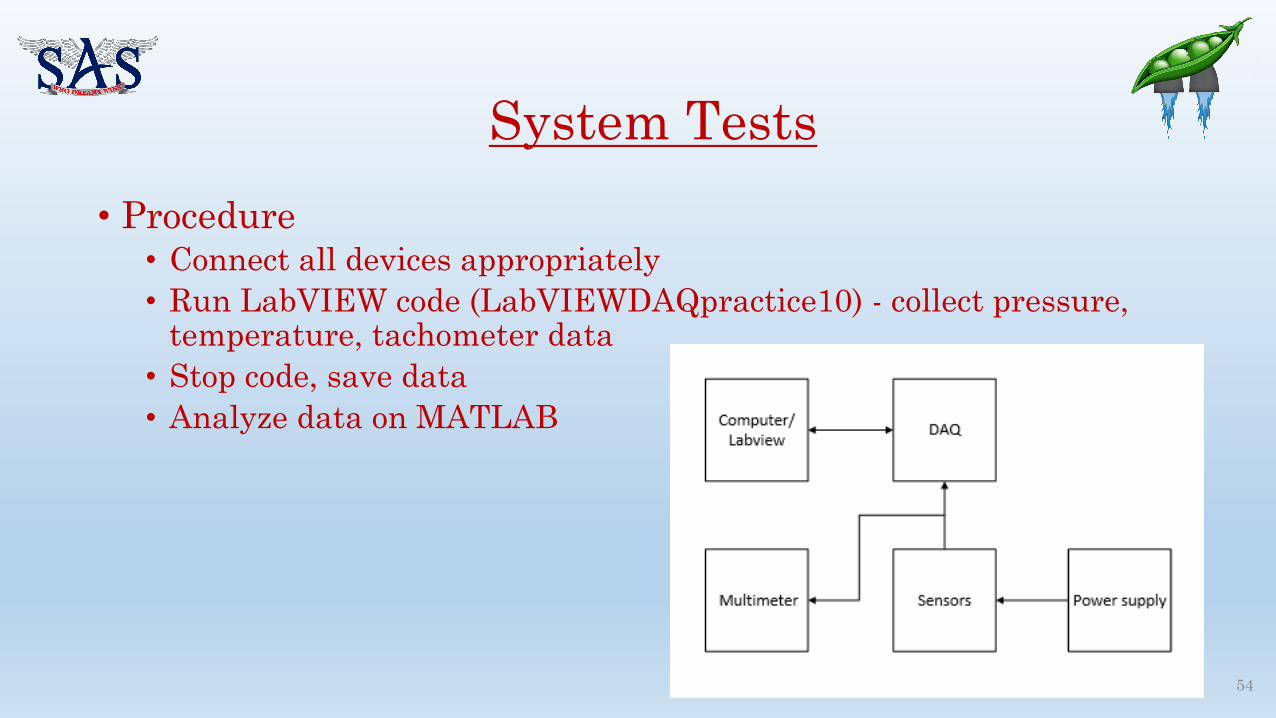
• Procedure• Connect all devices appropriately• Run LabVIEW code (LabVIEWDAQpractice10) - collect pressure,
temperature, tachometer data• Stop code, save data• Analyze data on MATLAB
System Tests
54

IO testing
55

Input test Results:• Nominal sample rate limited to 1 kHz
• Max error 4 mV (vs multimeter)
• Data spiking (right) – corrected by using lower sample rate (rate shown: 1 kHz)
Verified• Accuracy of thermocouple, pressure, and
tachometer readings• Maximum control loop rate• Control possible, gain limits to be
determined
56
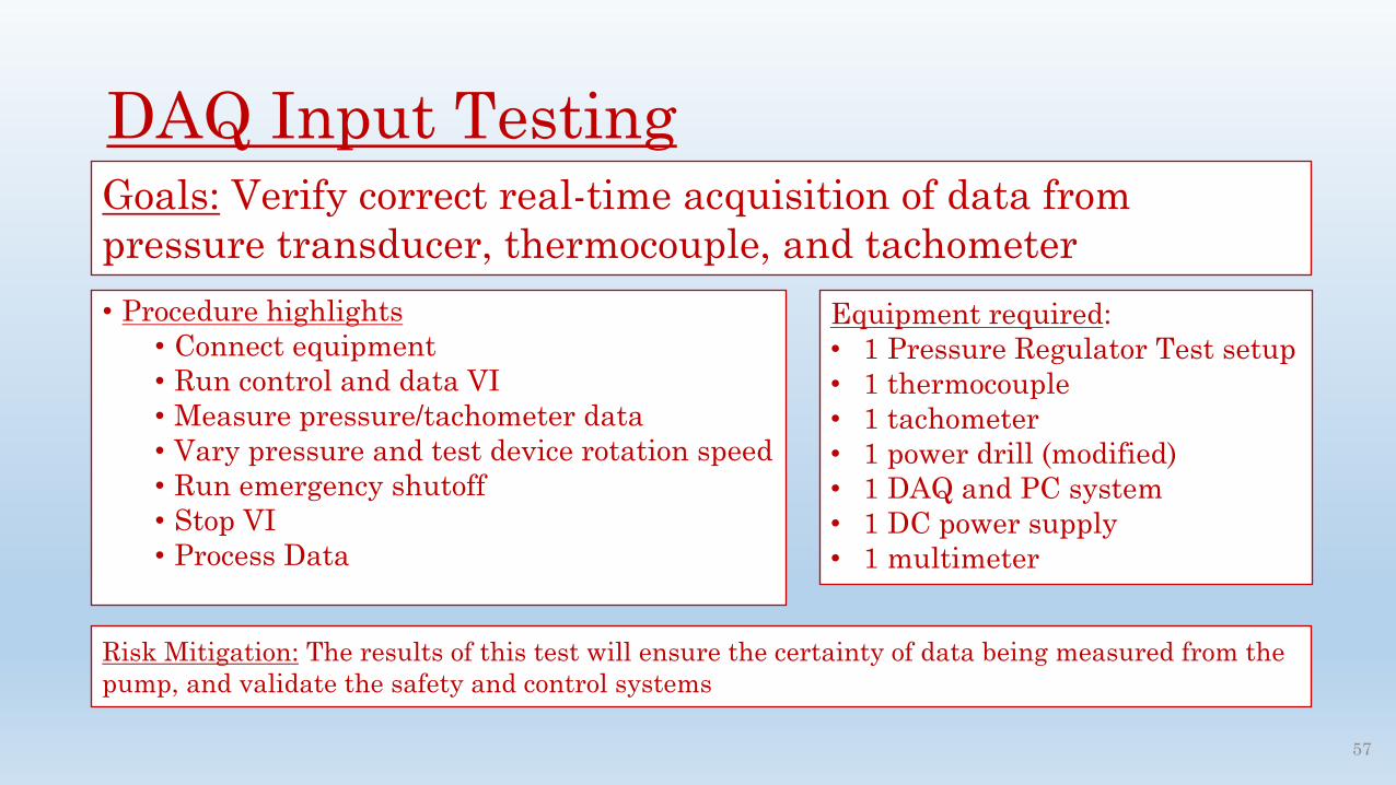
DAQ Input Testing• Justin & CesarGoals: Verify correct real-time acquisition of data from pressure transducer, thermocouple, and tachometer
Equipment required:• 1 Pressure Regulator Test setup• 1 thermocouple• 1 tachometer• 1 power drill (modified)• 1 DAQ and PC system• 1 DC power supply• 1 multimeter
• Procedure highlights• Connect equipment• Run control and data VI• Measure pressure/tachometer data• Vary pressure and test device rotation speed• Run emergency shutoff• Stop VI• Process Data
Risk Mitigation: The results of this test will ensure the certainty of data being measured from the pump, and validate the safety and control systems
57

58

59


![Division of Materials Chemistry – Polymer Controlled Synthesis · actions. We found that [10]CPP selectively encapsulated C60 forming the shortest fullerene-peapod, [10]CPP⊃C60,](https://img.pdfslide.net/doc/110x75/60a99b1b5c3efb00265d0c7b/division-of-materials-chemistry-a-polymer-controlled-synthesis-actions-we-found.jpg)