Embed Size (px)
Citation preview
a
ESTEC Keplerlaan 1 - 2201 AZ Noordwijk - The Netherlands Tel. (31) 71 5656565 - Fax (31) 71 5656040
D O C U M E N T
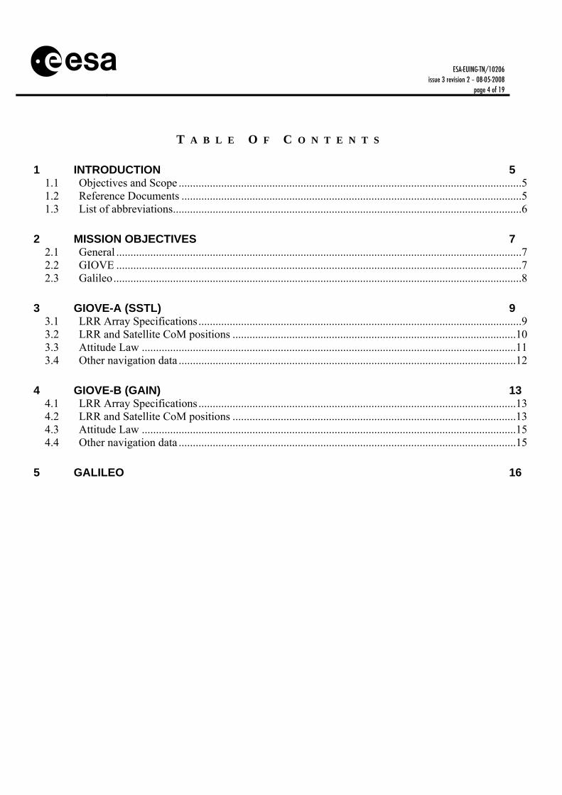
Tdocument title/ titre du documentT
PECIFICATION OF ALILEO AND PACE
EGMENT ROPERTIES ELEVANT FOR ATELLITE ASER ANGING
Tprepared by/préparé parT Galileo Project Office Treference/réferenceT ESA-EUING-TN/10206 Tissue/éditionT 3 Trevision/révisionT 2 Tdate of issue/date d’éditionT 08/05/2008 Tstatus/étatT TDocument type/type de document T
Technical Note
TDistribution/distributionT

ESA-EUING-TN/10206 issue 3 revision 2 – 08-05-2008
page 2 of 19
A P P R O V A L
TTitle TtitreT
Tissue TissueT
3 TrevisionTrevisionT
2
Tauthor TauteurT
R. Zandbergen, D. Navarro Tdate TdateT
08/05/2008
Tapproved by Tapprouvé byT
Marco Falcone Tdate TdateT
C H A N G E L O G
Treason for change /raison du changement T Tissue/issueT Trevision/revisionT Tdate/dateT
Enclose information about positions of LRR, CoM, and phase centre, together with yaw steering, mass, and cross-section area for satellites GSTBV2/A and GSTBV2/B. Change structure of document to focus it on the different satellites.
2 1 10/10/2005
Corrected Z component of phase centre for GSTBV2/B. Rephrased attitude law description for both GSTBV2A and B.
2 2 01/11/2005
Update GSTB-V2 name to GIOVE. Provided revised and current information from GIOVE-A. Provided D-PDR information for IOV satellites LRR
3 0 03/07/2006
Minor corrections in section numbering 3 1 22/02/2008
Update of GIOVE-A and B data 3 2 09/5/2008
C H A N G E R E C O R D
Issue: 3 Revision: 2

ESA-EUING-TN/10206 issue 3 revision 2 – 08-05-2008
page 3 of 19
Treason for change/raison du changement T Tpage(s)/page(s)T Tparagraph(s)/parag
raph(s)TTT
Updated orbital elements for GIOVE-A and GIOVE-B
7 2.2
Provision of LRR Phase Centre 13 4
Addition of LRR schematic 14 5
ESA-EUING-TN/10206 issue 3 revision 2 – 08-05-2008
page 4 of 19
T A B L E O F C O N T E N T S
TU1UT TUINTRODUCTIONUT 5 TU1.1UT TUObjectives and ScopeUT .........................................................................................................................5 TU1.2UT TUReference DocumentsUT ........................................................................................................................5 TU1.3UT TUList of abbreviationsUT...........................................................................................................................6
TU2UT TUMISSION OBJECTIVES UT 7 TU2.1UT TUGeneralUT ...............................................................................................................................................7 TU2.2UT TUGIOVE UT ...............................................................................................................................................7 TU2.3UT TUGalileoUT ................................................................................................................................................8
TU3UT TUGIOVE-A (SSTL) UT 9 TU3.1UT TULRR Array SpecificationsUT ..................................................................................................................9 TU3.2UT TULRR and Satellite CoM positionsUT ....................................................................................................10 TU3.3UT TUAttitude LawUT ....................................................................................................................................11 TU3.4UT TUOther navigation dataUT .......................................................................................................................12
TU4UT TUGIOVE-B (GAIN) UT 13 TU4.1UT TULRR Array SpecificationsUT ................................................................................................................13 TU4.2UT TULRR and Satellite CoM positionsUT ....................................................................................................13 TU4.3UT TUAttitude LawUT ....................................................................................................................................15 TU4.4UT TUOther navigation dataUT .......................................................................................................................15
TU5UT TUGALILEO UT 16
ESA-EUING-TN/10206 issue 3 revision 2 – 08-05-2008
page 5 of 19
1 INTRODUCTION
1.1 Objectives and Scope This document provides information about the relevant characteristics of the Galileo Spacecraft and orbits in order to allow an assessment by the International Laser Ranging Service of its capability to perform Satellite Laser Ranging support. In addition, this document provides information (when available) about spacecraft properties crucial for precise orbit determination such as LRR position, centre of mass position, attitude law, navigation signal phase centre, etc. Some of these values are still subject to verification (for instance, during GIOVE-A QAR) and will be updated in following versions of this document. The document applies both to the two experimental spacecraft flown as part of the Galileo System Test Bed V2, henceforth referred to as GIOVE-A and GIOVE-B, and to the operational Galileo spacecraft. For the latter, distinction is made between the In-Orbit Validation (IOV) and Full Operational Capability (FOC) phases.
1.2 Reference Documents RD-1 Galileo Satellite Laser Ranging
Retro-Reflector Specifications, ESA MEMO
-DEUI-NG-MEMO/01280, Issue 1.0, 6-8-2004
Issue 1.0 6-8-2004
RD-2 Galileo Global Component System Requirements Document
Issue 4.2 27-7-2004
RD-3 Space Segment Design and Justification
GSTBV2-SS-DD-SST-SC-0004
Issue 5 28/01/05
RD-4 Antenna ICD (Alenia) GSTBV2-SS-DR-SST-SC-0005
Rev 1 D 03/05/05
RD-5 GSTBV2A Laser Retroreflector
01733-ITM (no ESA ref code)
Rev 2 03/07/04
RD-6 GSTBV2 - LASER REFLECTOR GSTBV2 LRR Technical note - Response to RID 4383
GSTBV2-SS-TN-SST-PL-0022
N/A
RD-7 Navigation Antenna Mechanical Design and Analysis
RPT-GT2-0025-ALS Issue 3 16/02/05
RD-8 GSTBV2A RF Test Report RPT-GT2-0040-ALS Issue 1 18/02/05
RD-9 Propulsion Bay ICD GSTBV2-SS-DR-SST-SC-0001
Rev B 10/02/05
RD-10 AOCS Design Description and GSTBV2-SS-TN-SST-SC- Issue 2
ESA-EUING-TN/10206 issue 3 revision 2 – 08-05-2008
page 6 of 19
Justification File 0016 22/02/05 RD-11 Space-Segment DDDJF GSTBV2-DD-GAIN-0030 Issue 2A
29/11/04 RD-12 Mechanical Design
Description GSTBV2-DD-GAIN-0282 Issue 3
15/11/04 RD-13 Navigation Antenna PFM
Design Verification and Compliance Matrix
GSTBV2-SS-CAS-ENG-13 B
Issue 5 19/01/05
RD-14 Navigation Antenna ICD PFM-FM
GSTBv2-SS-CAS-ENG-16-B
Issue 1 Rev 1
06/09/04 RD-15 Satellite Budgets GSTBV2-BG-GAIN-0037 Issue 5 03/12/04 RD-16 Yaw Steering Guidance TN_60_0023 Issue 1
17/10/03 RD-17 GSTBv2-A Technical
Description Of the Laser Retroreflector Array
K01-Э170-00-00 TO Rev 1 2004
RD-18 Laser Retroreflector Design Description and Justification File
GAL-DDJF-ASTD-LRR-R-0015
Issue:1.0 15/07/2005
1.3 List of abbreviations AOCS Attitude and Orbit Control System CoM Centre of Mass FOC Full Operational Capability GIOVE Galileo In Orbit Validation Element GSTB Galileo System Test Bed GTRF Galileo Terrestrial Reference Frame IOV In-Orbit Validation ITRF International Terrestrial Reference Frame LRR Laser Retro-Reflector MEO Medium Earth Orbit RA Right Ascension QAR Qualification and Acceptance Review S/C Spacecraft SLR Satellite Laser Ranging SSTL Surrey Satellite Technology Ltd TBC To Be Confirmed

ESA-EUING-TN/10206 issue 3 revision 2 – 08-05-2008
page 7 of 19
2 MISSION OBJECTIVES
2.1 General This section specifies the mission objectives for the different S/C and operations phases, and includes the orbit parameters.
2.2 GIOVE GIOVE-A , also known as GSTB-V2/A, built by Surrey Satellite Technology Ltd (SSTL) of the UK, was launched on 28P
thP December 2005. GIOVE-B, also known as GSTB-V2/B, built
by Galileo Industries (GaIn), was launched on 26P
thP April 2008.
Both satellites missions have the same objectives:
- to secure the Galileo frequency allocations by providing a signal in space - to allow early experimentation with critical hardware (Signal In Space and On-Board
Clocks) and software systems - to demonstrate navigation service - to characterization of the MEO environment - additional experimentation
Precise evaluation characterisation of the performance of the on-board atomic clocks, of antenna infrastructure, and of signal properties requires a precise orbit determination, in which SLR will play an important role. Both routine SLR tracking and occasional campaigns with higher-intensity tracking will be required. The orbit defined for the operational test bed satellite is a near-circular ground track repeat orbit of 17 revolutions in (approximately) 10 sidereal days, with an inclination of 56º. The relevant orbit parameters are: GIOVE-A has currently the keplerian elements described below (8 May 2008 12:00:00)
• Semi-major Axis (km): 29632.822711 • Eccentricity: 0.000802 • Inclination (deg): 56.042 • RAAN (deg): 167.892 • Argument of Perigee (deg): 337.768 • Mean Anomaly (deg): 147.110
GIOVE-B has currently the keplerian elements described below (8 May 2008 12:00:00)
• Semi-major Axis (km): 29552.756161 • Eccentricity: 0.002243 • Inclination (deg): 56.011 • RAAN (deg): 202.911

ESA-EUING-TN/10206 issue 3 revision 2 – 08-05-2008
page 8 of 19
• Argument of Perigee (deg): 215.298 • Mean Anomaly (deg): 4.931
2.3 Galileo The final constellation will consist of 27 operational spacecraft equipped with identical Laser Retro-Reflectors (LRR). The satellites will be evenly distributed over 3 orbit planes, in a 27/3/1 Walker constellation. That means that the R.A. of ascending nodes of the three planes are separated by 120º and the spacecraft in each plane are separated by 40º in-plane. The orbit is the same as for the GIOVE spacecraft, i.e. a 10-day ground-track repeat orbit with 17 revolutions and an inclination of 56º. Each plane will include an additional (inactive) spare satellite, for which no SLR tracking will be requested as long as it is inactive. The relevant orbit parameters are: Semi-major axis: 29601 km Eccentricity: 0.002 Inclination: 56º Argument of perigee: 0º (TBC) RA of ascending node: 0º, 120º, 240º (TBC) The (up to) four Galileo satellites used in IOV will be launched in the 4P
thP quarter of 2007 for
a foreseen IOV phase duration of 6 months (extendable to 1 year). They will be identical to the FOC S/C, and they will have the same orbit parameters - no change in semi-major axis or inclination between IOV and FOC is foreseen. The IOV S/C will be collocated to allow simultaneous reception of the navigation signals, but the final decision whether all four S/C will be in one plane or subdivided over two planes, and whether they will also be separated by 40º, is not yet made. The objectives of SLR during IOV are similar to those for the GSTBV2 mission: to characterise on-board instrument properties using precise orbit determination, both on a routine basis and in occasional campaigns with more intensive tracking. During FOC, SLR data will contribute to the verification of the precise orbits based on microwave data and to the tie between the Galileo Terrestrial Reference Frame (GTRF) and ITRF.
ESA-EUING-TN/10206 issue 3 revision 2 – 08-05-2008
page 9 of 19
3 GIOVE-A (SSTL)
3.1 LRR Array Specifications Originally, GIOVE-A was planned to be equipped with a pair of identical LRR arrays separated by some distance on the nadir-facing side of the spacecraft. The final design deviates from this original approach, whereby the two patches have been co-located and form one integrated array of 76 coated cubes with a diameter of 27 mm each. The overall shape is trapezoidal. Specifications (RD-5): 1. OVERALL ENVELOPE (WITH COVER): 308 x 408 x 48 mm (excluding heads of
mounting screws) OVERALL ENVELOPE (WITH COVER): 308 x 408 x 54.5 mm (including heads of mounting screws)
OVERALL ENVELOPE (WITHOUT COVER): 306.8 x 405.5 x 41.5 mm 45 LRR ARRAY (WITHOUT COVER): 306.8 x 271.8 x 41.5 mm 31 LRR ARRAY (WITHOUT COVER): 239.5 x 254 x 41.5 mm 2. TOTAL WEIGHT (WITHOUT COVER): < 3.8 Kg 45 LRR ARRAY (WITHOUT COVER): < 2.2 Kg 31 LRR ARRAY (WITHOUT COVER): < 1.6 Kg 3. COORDINATES OF CENTRE OF GRAVITY OF 76 LRR ARRAY AS AN ASSEMBLY. Xg=89 mm, Yg=176.8 mm, Zg=24.37 mm (Referred to reference hole) 4. CENTRE OF GRAVITY OF 45 LRR ARRAY: Xg = 113.7 mm (Referred to reference hole) Yg = 100.0 mm Zg = 24.5 mm CENTRE OF GRAVITY OF 31 LRR ARRAY: Xg = 53.2 mm (Referred to reference hole) Yg = 289.0 mm Zg = 24.2 mm 5. MOMENT OF INERTIA OF 76 LRR ARRAY: Jx = 47964 Kg x mm^2 (Referred to 76 LRR array CofG) Jy = 21881 Kg x mm^2 Jz = 69038.6 Kg x mm^2 MOMENT OF INERTIA OF 45 LRR ARRAY: Jx = 8887.9 Kg x mm^2 (Referred to 45 LRR array CofG) Jy = 15133.4 Kg x mm^2 Jz = 23546.8 Kg x mm^2 MOMENT OF INERTIA OF 31 LRR ARRAY: Jx = 4319.5 Kg x mm^2 (Referred to 31 LRR array CofG) Jy = 7261.8Kg x mm^2 Jz = 11250.3 Kg x mm^2 6. MATERIAL (BASE AND RR HOLDER): ALUMINIUM ALLOY AМг6

ESA-EUING-TN/10206 issue 3 revision 2 – 08-05-2008
page 10 of 19
7. MOUNTING SCREWS: 9 pcs. M5 x 20.0 mm LONG CAP HEAD, STAINLESS STEEL A2-70 8. MOUNTING WASHER: 9 pcs. DIA 5.3 мм, STAINLESS STEEL A2 9. CONTACT AREA (): 1,876.0 mm P
2P
45 LRR ARRAY: 1061 mm P
2P
31 LRR ARRAY: 815 mm P
2P
10. OVERALL MOUNTING SURFACE FLATNESS: < 0.2 mm Actual flatness is 0.04 mm 11. FLATNESS FOR EACH FOOT: same as for item 10 12. MOUNTING SURFACE ROUGHNESS: Ra1.6 13. SURVIVAL TEMPERATURE RANGE: from -150°С to +125°С A detailed drawing is attached as Annex A.
3.2 LRR and Satellite CoM positions Coordinate of the Optical centre of 76 LRR array with respect satellite reference frame (RD-4, RD-6, RD-16): X = -832 mm Y = -654 mm Z = 1476 mm Coordinate of the S/C centre of gravity (valid as of March 2006) X = -4 mm Y = 1 mm Z = 796 mm
ESA-EUING-TN/10206 issue 3 revision 2 – 08-05-2008
page 11 of 19
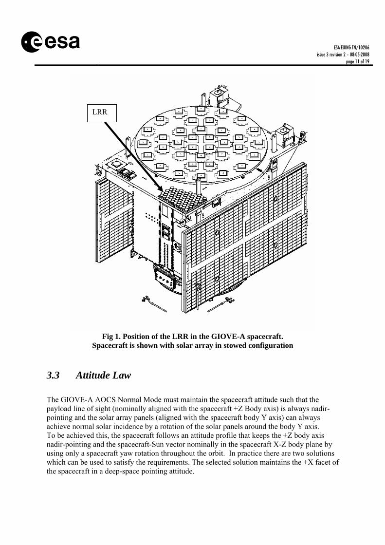
Fig 1. Position of the LRR in the GIOVE-A spacecraft.
Spacecraft is shown with solar array in stowed configuration
3.3 Attitude Law The GIOVE-A AOCS Normal Mode must maintain the spacecraft attitude such that the payload line of sight (nominally aligned with the spacecraft +Z Body axis) is always nadir-pointing and the solar array panels (aligned with the spacecraft body Y axis) can always achieve normal solar incidence by a rotation of the solar panels around the body Y axis. To be achieved this, the spacecraft follows an attitude profile that keeps the +Z body axis nadir-pointing and the spacecraft-Sun vector nominally in the spacecraft X-Z body plane by using only a spacecraft yaw rotation throughout the orbit. In practice there are two solutions which can be used to satisfy the requirements. The selected solution maintains the +X facet of the spacecraft in a deep-space pointing attitude.
LRR

ESA-EUING-TN/10206 issue 3 revision 2 – 08-05-2008
page 12 of 19
It is foreseen that the theoretical attitude will not be achieved at times where the beta angle (angle between the sun and the orbital plane) is small, due to limitations in the reactions wheels and to poor yaw measurement (sun co-linearity). In addition, during eclipse, it is expected that the yaw error can reach values of up to 18 degrees.
3.4 Other navigation data The phase centre for the navigation signal is provided here to complement the necessary information needed to perform precise orbit determination (RD-4, RD-7 and RD-8)
E5a + E5b E6 E2/L1/E2 X = 0.0 mm Y = 0.0 mm Z = 1690.0 mm
X = 0.0 mm Y = 0.0 mm Z = 1665.0 mm
X = 0.0 mm Y = 0.0 mm Z = 1658.0 mm
The s/c mass is 582.8 Kg (valid as of March 2006). The approximate cross-section Area is 9 squared metres, with a CBSRP B (Solar Pressure Radiation factor) equals 1.37 (assuming cannonball model, according to equation 1)
mAWCa SRP= (Eq 1)
A is cross-section Area, W = 4.56·10P
-6P N/mP
2P, m is satellite mass, RBsun B is mean distance to Sun.
ESA-EUING-TN/10206 issue 3 revision 2 – 08-05-2008
page 13 of 19
4 GIOVE-B (GAIN)
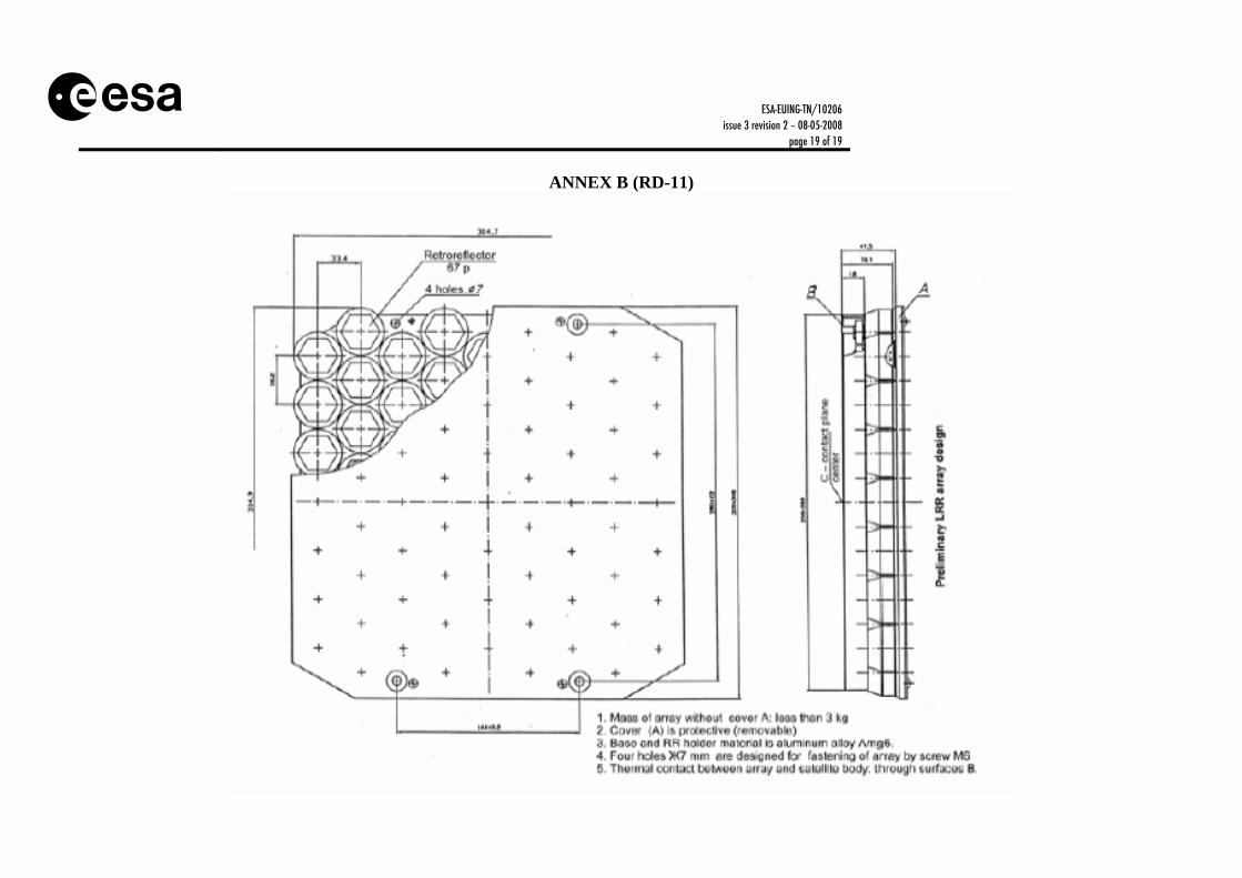
4.1 LRR Array Specifications Specifications have been extracted from industrial documentation. (RD-11) Size: 305mm x 305mm x 42 mm Number of prisms: 67 Prism diameter: 27 mm (light area) Material: optical grade fused silica, aluminium-coated Temperature range: from -125°С to +125°С Field of view: 12 degrees (half-cone) Cubes are coated in Aluminium. A detailed drawing is attached as Annex B.
4.2 LRR and Satellite CoM positions The LRR is located on the +Z facet (See Fig.2). The coordinates of the CoP of the LRR array with respect to the satellite reference frame (See Fig.3 for the position of the reflective surface; cube height is 19.1 mm, refractive index is 1.46)
X = -807.5 mm Y = 297.5 mm Z = 2267.6 mm
Coordinate of the S/C CoM (beginning of life, deployed solar array configuration) with respect to the satellite reference frame:
X = -3.2 mm Y = 3.4 mm Z = 937.5 mm

ESA-EUING-TN/10206 issue 3 revision 2 – 08-05-2008
page 14 of 19
Fig 2. Position of LRR in GIOVE-B.
Spacecraft is shown with solar array in stowed configuration
Fig 3. LRR schematic in GIOVE-B.
Y
X
Z
LRR

ESA-EUING-TN/10206 issue 3 revision 2 – 08-05-2008
page 15 of 19
4.3 Attitude Law GIOVE-B follows a yaw steering law such that the body +Z axis points continuously to Nadir, together with a rotation performed around the Z axis that maintains the S/C Y axis perpendicular to the Sun. The +X spacecraft panel is maintained away from the sun. (RD-10). As with GIOVE-A, it is foreseen that the theoretical attitude will not be achieved at times where the beta angle (angle between the sun and the orbital plane) is small, due to limitations in the reactions wheels and to poor yaw measurement (sun co-linearity). In addition, during eclipse, it is expected that the yaw error can reach values of the same order as GIOVE-A.
4.4 Other navigation data L-band phase centres (RD-13 and RD-14)
E5a + E5b E6 E2/L1/E2 X = 0.0 mm Y = 0.0 mm Z = 2288.7 mm
X = 0.0 mm Y = 0.0 mm Z = 2287.6 mm
X = 0.0 mm Y = 0.0 mm Z = 2289.15 mm
The s/c mass is 497.6 Kg (BOL). The approximate cross-section Area is 12 squared metres, with a CBSRP B (Solar Pressure Radiation factor) equals 1.37 (assuming cannonball model, according to equation 1)

ESA-EUING-TN/10206 issue 3 revision 2 – 08-05-2008
page 16 of 19
5 GALILEO The current specifications by industry of the LRR size are extracted from industrial documentation (RD-18) at Delta Preliminary Design Review stage.
• Length: 522 mm • Width: 424 mm • Height: 45 mm • 78 Non-coated fused silica mirrors • Mass: 4.7 kg
LRR is specified to operate under inclination angles up to 15 ° (roll and pitch directions) with an overall effective reflecting area ≥ 660 cm2 as required from viewed from any point on the Earth (i.e. assuming nominal S/C attitude).
Fig 3. Position of LRR in a Galileo Satellites.

ESA-EUING-TN/10206 issue 3 revision 2 – 08-05-2008
page 17 of 19
Fig 4. LRR top view
END OF DOCUMENT

ESA-EUING-TN/10206 issue 3 revision 2 – 08-05-2008
page 18 of 19
ANNEX A (RD-5)
ESA-EUING-TN/10206 issue 3 revision 2 – 08-05-2008
page 19 of 19
ANNEX B (RD-11)