Embed Size (px)
Citation preview
©A
BB
Gro
up -
1-
9-N
ov-0
7
PEEC based simulations in Power Electronics applications
Stanislav Skibin
ABB Switzerland
©A
BB
Gro
up -
2-
9-N
ov-0
7Outline
1. Power Electronics applications2. EMC aspects in the power electronics area
1. Current switching with IGBT power modules (PM)2. Parallelization of switching elements3. Coupling mechanisms in PMs
3. Abstraction modeling levels1. Component level
1. IGBT MV power module2. IGBT HV power module3. Gate Commutated Thyristor (GCT)
2. Application level1. Frequency converter2. HVDC-light
4. Export of the PEEC impedance matrix5. Summary
©A
BB
Gro
up -
3-
9-N
ov-0
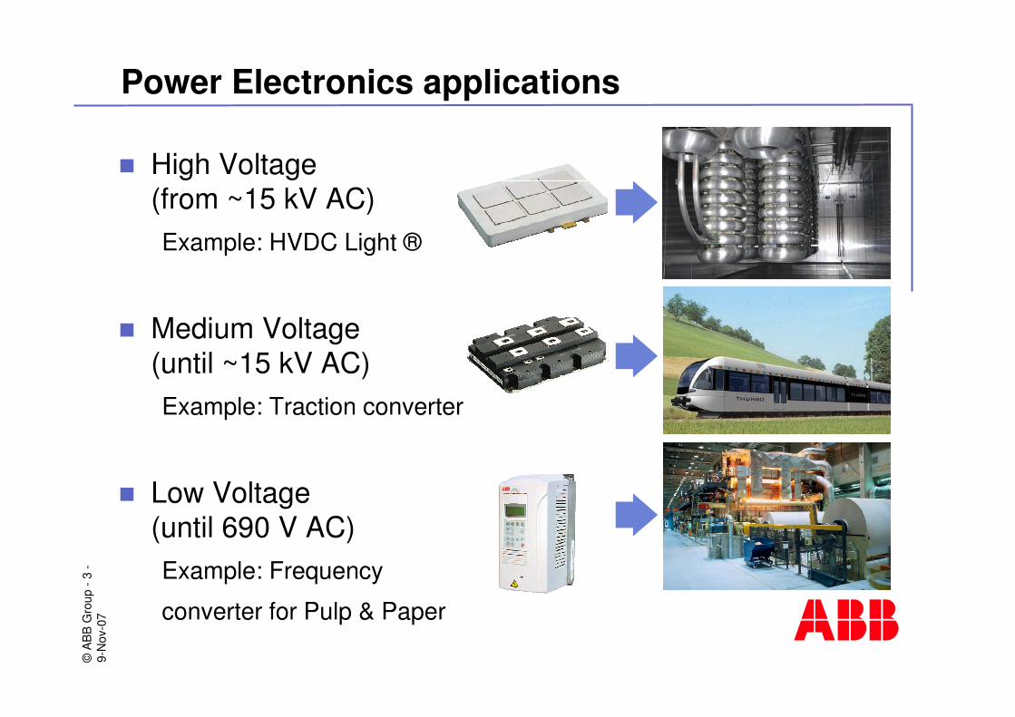
7Power Electronics applications
� High Voltage (from ~15 kV AC)Example: HVDC Light ®
� Medium Voltage (until ~15 kV AC)Example: Traction converter
� Low Voltage (until 690 V AC)Example: Frequency
converter for Pulp & Paper

©A
BB
Gro
up -
4-
9-N
ov-0
7EMC aspects in the power electronics area
=≈≈≈≈
3 Phase, AC f2 = 0 - 120 Hz
Converter DC/AC(Power Module)
=≈≈≈≈
3 Phase, ACf1 = 50 / 60 Hz
RectifierAC/DC
DC-caps
Pulse Width Modulation (PWM): fPWM = 5 – 16 kHz
Current switching in frequency converters
©A
BB
Gro
up -
5-
9-N
ov-0
7EMC aspects in the power electronics area
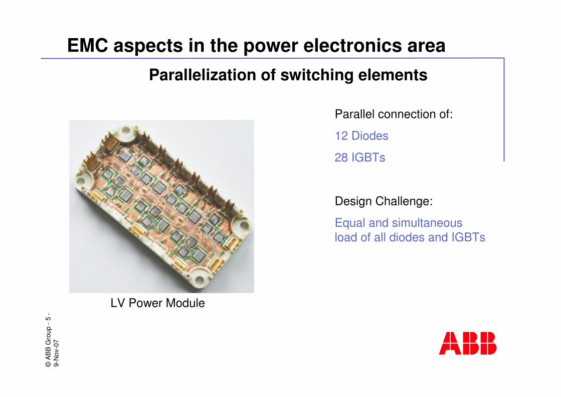
Parallelization of switching elements
Parallel connection of:
12 Diodes
28 IGBTs
Design Challenge:
Equal and simultaneous load of all diodes and IGBTs
LV Power Module
©A
BB
Gro
up -
6-
9-N
ov-0
7EMC aspects in the power electronics area
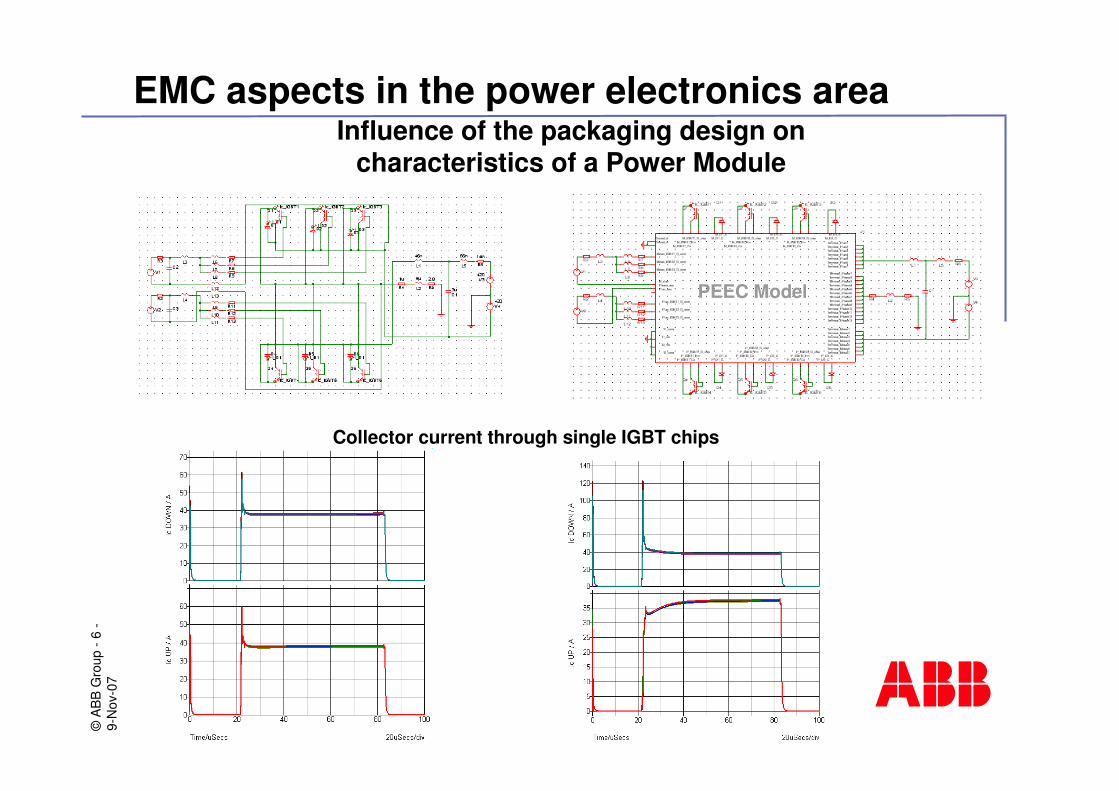
Influence of the packaging design on characteristics of a Power Module
PEEC Model
Collector current through single IGBT chips
©A
BB
Gro
up -
7-
9-N
ov-0
7EMC aspects in the power electronics area
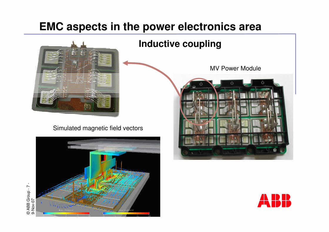
Inductive coupling
MV Power Module
Simulated magnetic field vectors
©A
BB
Gro
up -
8-
9-N
ov-0
7EMC aspects in the power electronics area
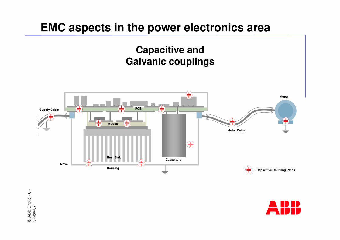
Capacitive and Galvanic couplings
Motor Cable
Motor
Heat Sink
Housing
PCB
Module
Capacitors Drive
Supply Cable
= Capacitive Coupling Paths
©A
BB
Gro
up -
9-
9-N
ov-0
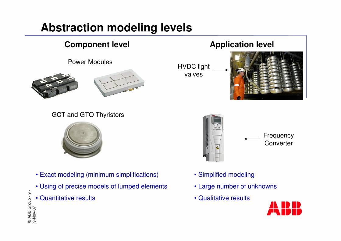
7Abstraction modeling levels
Component level
• Exact modeling (minimum simplifications)
• Using of precise models of lumped elements
• Quantitative results
Application level
• Simplified modeling
• Large number of unknowns
• Qualitative results
Power Modules
GCT and GTO Thyristors
Frequency Converter
HVDC light valves
©A
BB
Gro
up -
10-
9-N
ov-0
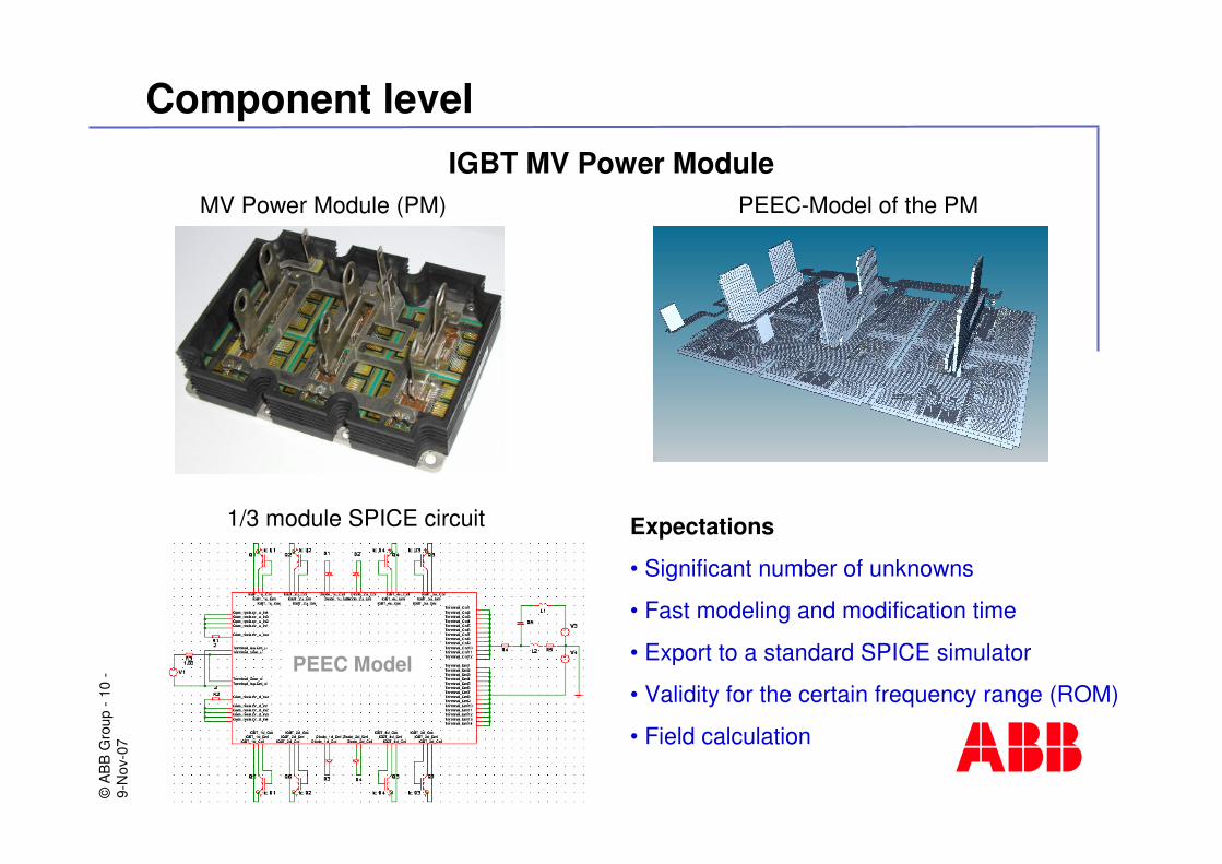
7Component level
IGBT MV Power ModuleMV Power Module (PM) PEEC-Model of the PM
1/3 module SPICE circuit Expectations
• Significant number of unknowns
• Fast modeling and modification time
• Export to a standard SPICE simulator
• Validity for the certain frequency range (ROM)
• Field calculation
PEEC Model

©A
BB
Gro
up -
11-
9-N
ov-0
7Component level
IGBT HV Power Module
Expectations
• Significant number of unknowns
• Fast modeling and modification time
• Export to a standard SPICE simulator
• Validity for the certain frequency range (ROM)
• Field calculation
I-PEEC Simulation Results
I-PEEC Model
©A
BB
Gro
up -
12-
9-N
ov-0
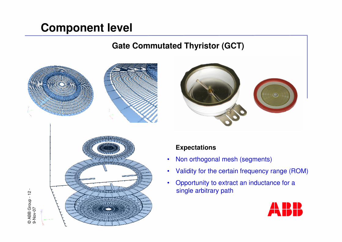
7Component level
Gate Commutated Thyristor (GCT)
Expectations
• Non orthogonal mesh (segments)
• Validity for the certain frequency range (ROM)
• Opportunity to extract an inductance for asingle arbitrary path
©A
BB
Gro
up -
13-
9-N
ov-0
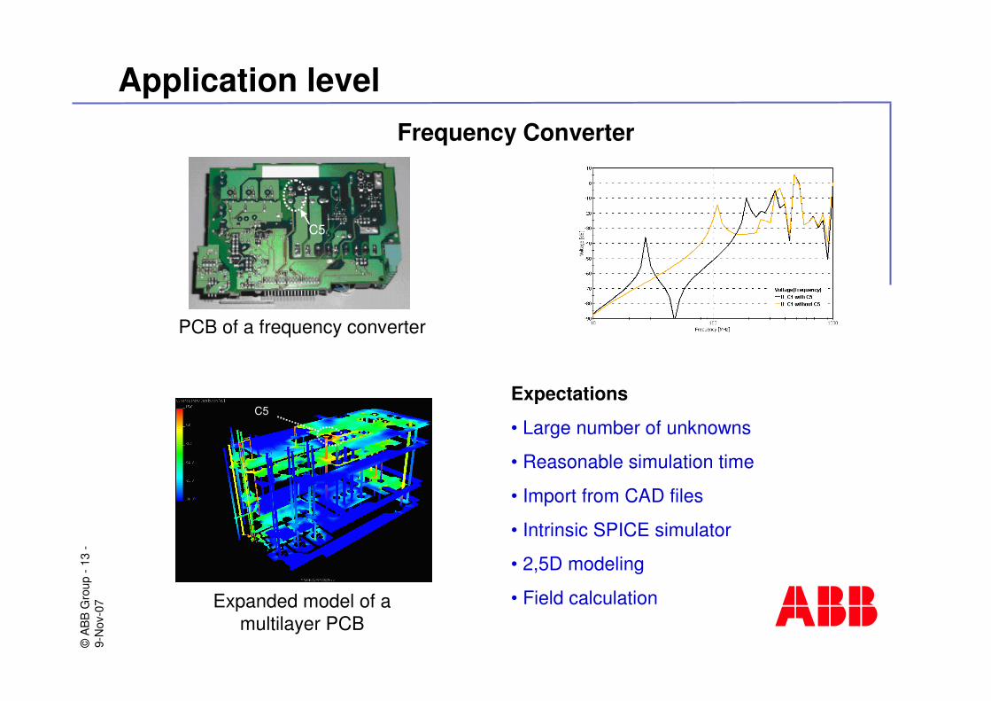
7Application level
Frequency Converter
C5
C5 Expectations
• Large number of unknowns
• Reasonable simulation time
• Import from CAD files
• Intrinsic SPICE simulator
• 2,5D modeling
• Field calculation
PCB of a frequency converter
Expanded model of a multilayer PCB
©A
BB
Gro
up -
14-
9-N
ov-0
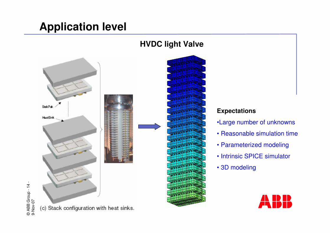
7Application level
HVDC light Valve
Expectations
•Large number of unknowns
• Reasonable simulation time
• Parameterized modeling
• Intrinsic SPICE simulator
• 3D modeling
©A
BB
Gro
up -
15-
9-N
ov-0
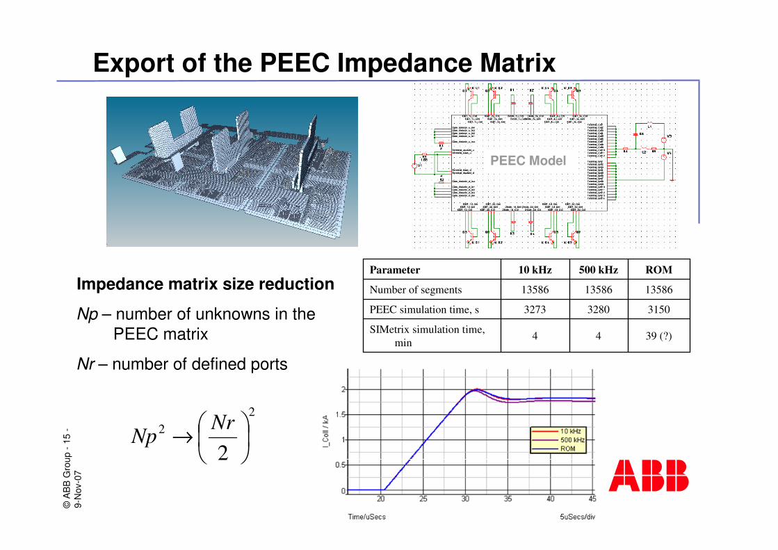
7Export of the PEEC Impedance Matrix
22
2��
���
�→ NrNp
Impedance matrix size reduction
Np – number of unknowns in thePEEC matrix
Nr – number of defined ports
39 (?)44SIMetrix simulation time, min
315032803273PEEC simulation time, s
135861358613586Number of segments
ROM500 kHz10 kHzParameter
PEEC Model
©A
BB
Gro
up -
16-
9-N
ov-0
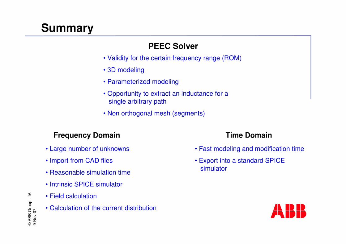
7Summary
PEEC Solver
Time Domain
• Large number of unknowns
• Import from CAD files
• Reasonable simulation time
• Intrinsic SPICE simulator
• Field calculation
• Calculation of the current distribution
• Fast modeling and modification time
• Export into a standard SPICEsimulator
• Validity for the certain frequency range (ROM)
• 3D modeling
• Parameterized modeling
• Opportunity to extract an inductance for asingle arbitrary path
• Non orthogonal mesh (segments)
Frequency Domain


![the PEEC Method Author(s) CAO, Y; Jiang, L; Ruehli, A · The partial element equivalent circuit (PEEC) method, which was proposed in the 1970s [6]–[9], is based on the EFIE with](https://img.pdfslide.net/doc/110x75/5f371f067b279a4660363651/the-peec-method-authors-cao-y-jiang-l-ruehli-a-the-partial-element-equivalent.jpg)