Embed Size (px)
Citation preview
PEER-TO-PEER 3D/MULTI-VIEW VIDEO STREAMING
by
Yan Ding
B.Sc., Zhejiang University, 2007
a Thesis submitted in partial fulfillment
of the requirements for the degree of
Master of Applied Science
in the School
of
Computing Science
c⃝ Yan Ding 2011
SIMON FRASER UNIVERSITY
April 2011
All rights reserved. However, in accordance with the Copyright Act of
Canada, this work may be reproduced without authorization under the
conditions for Fair Dealing. Therefore, limited reproduction of this
work for the purposes of private study, research, criticism, review and
news reporting is likely to be in accordance with the law, particularly
if cited appropriately.
APPROVAL
Name: Yan Ding
Degree: Master of Applied Science
Title of Thesis: Peer-to-peer 3D/multi-view video streaming
Examining Committee: Dr. Arrvindh Shriraman
Assistant Professor of Computing Science
Chair
Dr. Jiangchuan Liu
Senior Supervisor
Associate Professor of Computing Science
Dr. Mohamed Hefeeda
Supervisor
Associate Professor of Computing Science
Dr. Jian Pei
Internal Examiner
Associate Professor of Computing Science
Date Approved:
ii
Abstract
The recent advances in stereoscopic video capture, compression and display have made 3D
video a visually appealing and costly affordable technology. More sophisticated multi-view
videos have also been demonstrated. Yet their remarkably increased data volume poses
greater challenges to the conventional client/server systems. The stringent synchroniza-
tion demands from different views further complicate the system design. In this thesis, we
present an initial attempt toward efficient streaming of 3D videos over peer-to-peer networks.
We show that the inherent multi-stream nature of 3D video makes playback synchroniza-
tion more difficult. We address this by a 2-stream buffer, together with a novel segment
scheduling. We further extend our system to support multi-view video with view diver-
sity and dynamics. We have evaluated our system under different end-system and network
configurations with typical stereo video streams. The simulation results demonstrate the
superiority of our system in terms of scalability, streaming quality and dealing with view
dynamics.
Key Words: 3D/Multi-view Video, Peer-to-Peer Network, Segment Scheduling
iii
Acknowledgments
Firstly I would like to show my deepest gratitude to my senior supervisor, Dr. Jiangchuan
Liu for his continuous support and encouragement over these years. Through each insightful
discussion with him, I learnt the ways of thinking and doing research. It is his knowledge,
patience and invaluable suggestions that help me finish this thesis.
I would like to thank my supervisor Dr. Mohamed Hefeeda and my examiner Dr. Jian
Pei serving on my committee and reviewing my thesis. I would like to thank Dr. Arrvindh
Shriraman for taking the time to chair my thesis defense.
I would like to thank all my colleagues in our Multimedia and Networking Group for
their kindness and help on my academic work and studying life.
Finally, I would like to thank my whole family for their endless love, support and en-
couragement. I would not have made it without them. This thesis is dedicated to them.
iv
Contents
Approval ii
Abstract iii
Acknowledgments iv
Contents v
List of Tables vii
List of Figures viii
1 Introduction 1
1.1 Introduction . . . . . . . . . . . . . . . . . . . . . . . . . . . . . . . . . . . . . 1
1.2 Thesis Organization . . . . . . . . . . . . . . . . . . . . . . . . . . . . . . . . 3
2 Background and Related Work 4
2.1 Overview of Peer-to-Peer Networks . . . . . . . . . . . . . . . . . . . . . . . . 4
2.1.1 File Sharing . . . . . . . . . . . . . . . . . . . . . . . . . . . . . . . . . 5
2.1.2 Live and On-Demand Streaming . . . . . . . . . . . . . . . . . . . . . 6
2.1.3 Overlay Construction and Segment Scheduling . . . . . . . . . . . . . 7
2.2 3D/Multi-view Video . . . . . . . . . . . . . . . . . . . . . . . . . . . . . . . . 9
2.2.1 Generation, Encoding/Decoding and Display . . . . . . . . . . . . . . 10
2.2.2 Media Synchronization . . . . . . . . . . . . . . . . . . . . . . . . . . . 11
2.3 Related Work . . . . . . . . . . . . . . . . . . . . . . . . . . . . . . . . . . . . 11
v
3 P2P 3D/Mulit-view Streaming System 14
3.1 System Model . . . . . . . . . . . . . . . . . . . . . . . . . . . . . . . . . . . . 14
3.2 Buffer Management . . . . . . . . . . . . . . . . . . . . . . . . . . . . . . . . . 16
3.3 Stereo Segment Scheduling . . . . . . . . . . . . . . . . . . . . . . . . . . . . 18
3.3.1 Problem Statement . . . . . . . . . . . . . . . . . . . . . . . . . . . . . 18
3.3.2 Algorithms and Analysis . . . . . . . . . . . . . . . . . . . . . . . . . . 20
3.4 Extension to Multi-view . . . . . . . . . . . . . . . . . . . . . . . . . . . . . . 25
3.5 Discussion . . . . . . . . . . . . . . . . . . . . . . . . . . . . . . . . . . . . . . 27
4 Evaluation 30
4.1 Simulation Setup . . . . . . . . . . . . . . . . . . . . . . . . . . . . . . . . . . 30
4.2 3D Video Performance . . . . . . . . . . . . . . . . . . . . . . . . . . . . . . . 31
4.2.1 Sep-Streaming vs. Mix-Streaming . . . . . . . . . . . . . . . . . . . . 31
4.2.2 Comparison with Optimal . . . . . . . . . . . . . . . . . . . . . . . . . 34
4.2.3 Comparison with Other Schedulers . . . . . . . . . . . . . . . . . . . . 34
4.2.4 Impact of Partner Sorting . . . . . . . . . . . . . . . . . . . . . . . . . 38
4.3 Multi-view Stereo with View Change . . . . . . . . . . . . . . . . . . . . . . . 39
5 Conclusion and Future Work 43
Bibliography 44
vi
List of Tables
3.1 Notations in BMF algorithm and their definitions . . . . . . . . . . . . . . . . 20
3.2 Notations in HPF algorithm and their definitions . . . . . . . . . . . . . . . . 24
4.1 Bandwidth capacity and peer distribution . . . . . . . . . . . . . . . . . . . . 31
vii
List of Figures
2.1 Client/server model and P2P model . . . . . . . . . . . . . . . . . . . . . . . 5
2.2 Tree-based and mesh-based data dissemination . . . . . . . . . . . . . . . . . 8
2.3 (a) Peer D’s sliding buffer window (segments with solid lines are available
in the local buffer, and those with dotted lines are not); (b) D schedules
missing segments from partners A, B, C and E (each partner has its bitmap
and available upload bandwidth) . . . . . . . . . . . . . . . . . . . . . . . . . 9
2.4 3D video generation and encoding . . . . . . . . . . . . . . . . . . . . . . . . 11
3.1 2-stream buffer: (a) User changes viewpoint from i to i+ 1 (status 1− > 2),
and stays watching (status 2− > 3); (b) Buffer details for a fixed viewpoint
(segments with solid lines are available in the local buffer, and those with
dotted lines are not) . . . . . . . . . . . . . . . . . . . . . . . . . . . . . . . . 16
3.2 Cases of 2-stream buffer scheduling . . . . . . . . . . . . . . . . . . . . . . . . 17
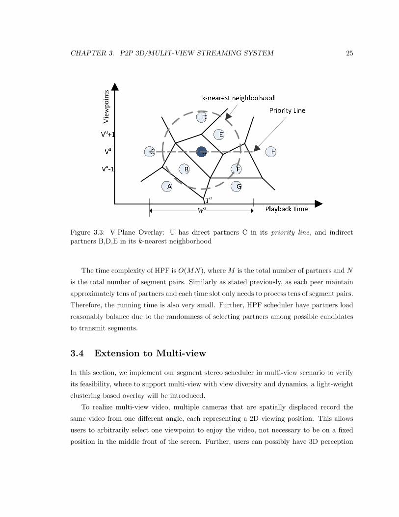
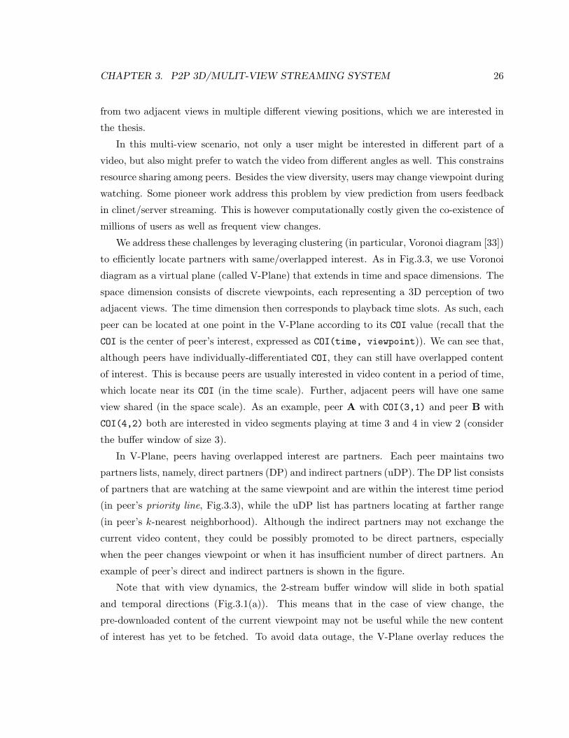
3.3 V-Plane Overlay: U has direct partners C in its priority line, and indirect
partners B,D,E in its k-nearest neighborhood . . . . . . . . . . . . . . . . . . 25
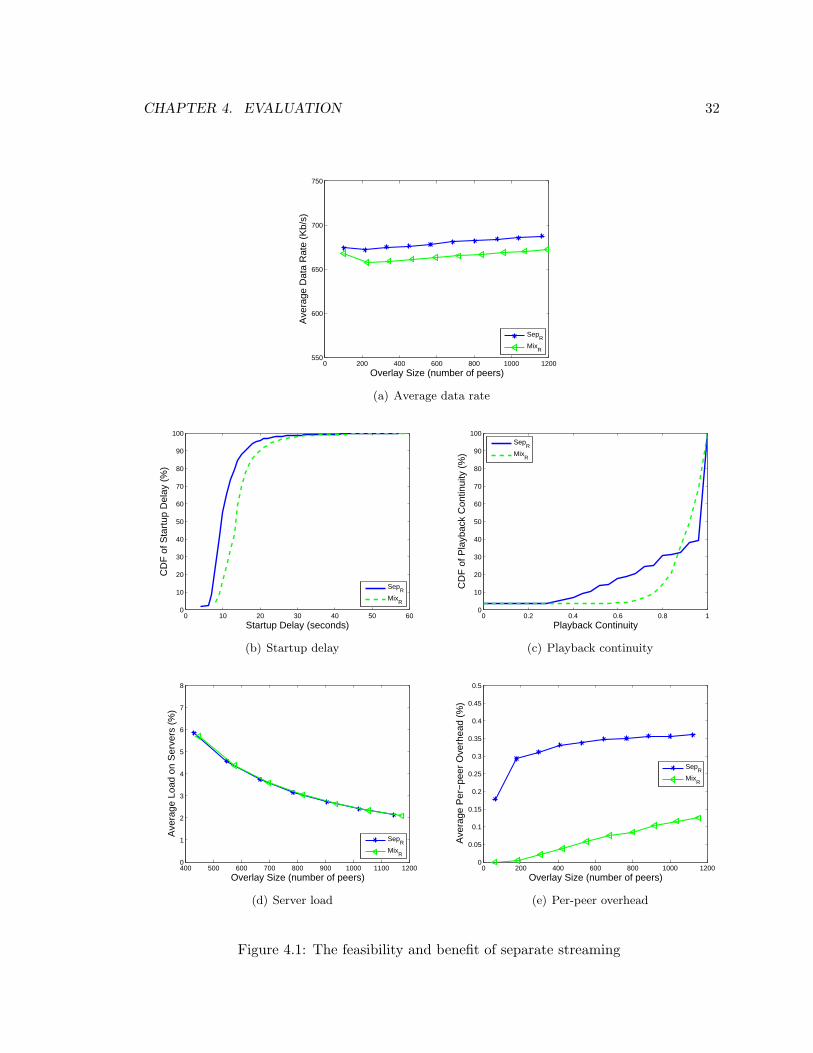
4.1 The feasibility and benefit of separate streaming . . . . . . . . . . . . . . . . 32
4.2 Performance comparison of the optimal (OPT) and the two proposed algo-
rithms (BMF and HPF) . . . . . . . . . . . . . . . . . . . . . . . . . . . . . . 35
4.3 Performance comparison of the proposed BMF algorithm and two other pop-
ular algorithms (RF and Random) . . . . . . . . . . . . . . . . . . . . . . . . 37
4.4 Impact of buffer window sizes . . . . . . . . . . . . . . . . . . . . . . . . . . . 38
4.5 Impact of peer arrival rates . . . . . . . . . . . . . . . . . . . . . . . . . . . . 38
4.6 Impact of partner sorting on BMF performance . . . . . . . . . . . . . . . . 40
4.7 Multi-view stereo with view change and the impact of uDP size . . . . . . . 42
viii
Chapter 1
Introduction
1.1 Introduction
The recent advances in stereoscopic video capture, compression, and display have made 3
Dimensional (3D) video a visually appealing and costly affordable technology. We have
witnessed a series of new releases of 3D movies in the past two years (e.g., Avatar), with
much more being just announced. FIFA, partnered with Sony, deliver 3D videos from 25
matches of the 2010 World Cup in South Africa, debuting a technology breakthrough in the
broadcast history. The abundant content, together with the dramatically decreasing price,
have become driving forces to the vast growth of 3D-capable disc players and LED TVs,
or even notebooks (e.g., Toshiba Satellite A665) in the market, which are quickly sweeping
away the conventional 2D devices.
3D video (also referred as stereo Video) is perceived by humans with additional three-
dimensional depth, which is resulting from the spatial disparity of two slightly different
streams for left and right eyes’ viewpoints respectively. Currently, the popular H.264/AVC
coding standard has well supported 3D video through its MVC (Multiple Video Coding)
extension [42]. Beyond local storage and playback, faster home broadband connections have
also fostered 3D video streaming over the Internet. Cisco predicted that 3D and high-
definition video will increase 13 times between 2009 and 2014. By 2014, annual global IP
traffic would reach almost three-fourths of a zettabyte (i.e., 0.75 trillion gigabytes), and
3D and high-definition video would comprise about 42% of it. The most popular video
sharing site, Youtube, has promoted to develop a stereoscopic player since July 2009, and
is currently experimenting over 100 experimental 3D videos supporting ten viewing styles.
1
CHAPTER 1. INTRODUCTION 2
There have been a number of pioneer academic works on streaming 3D video over the In-
ternet, too; see [32] [41] [30]. Most of them, like those commercial products, are client/server
based however. This classical communication paradigm has already suffered from streaming
the traffic-intensive 2D videos, and the remarkably increased data volume of 3D videos poses
even greater challenges. Peer-to-peer (P2P) streaming, on the other hand, has shown to be
a highly scalable and practical alternative [38]. We believe that it can be a candidate of
great potentials for 3D video streaming as well, particularly considering that its commercial
success in delivering live TV or on-demand movies, and many these contents are in the
transition from 2D to 3D.
The inherent multi-stream nature of 3D video unfortunately makes segment scheduling
more difficult than that of 2D video, which has already been proved to be NP-Complete
problem [62]. This is because, to enable stereoscopic perception at the user side, not only
segments in one stream have to arrive before playback deadlines, but also they have to
be paired with corresponding segments with the same playback time in the other stream.
Poor synchronization between streams prolongs the playback delay, and would even cause
spatial displacement of objects in the two views, resulting in false parallax perception [48].
The problem is severe in a peer-to-peer overlay, given the existence of multiple senders and
node churns. For multi-view video, since a user is only interested in a subset of the views
but can switch over views, the challenge becomes even acuter with such view diversity and
dynamics.
In this thesis, we focus on the stereo segment scheduler design, a key component for
streaming 3D/multi-view videos over P2P systems. The thesis has the following contribu-
tions:
• We present an initial attempt toward efficient streaming of 3D/multi-view videos over
a P2P network. We show that the separated streaming brings comparable streaming
service (higher streaming rate, lower startup delay and smoother playback) of the
mixed streaming, with lower system cost and better scalability (lower server load).
• We show that the inherent multi-stream nature of 3D video makes segment scheduling
more difficult, particularly, we formulate the stereo segment scheduling problem as a
Binary Quadratic Programming (BQP) problem and discuss its hardness.
• We develop two efficient algorithms to allow peers frequently update the scheduling,
and provide theoretical analysis on their performance guarantee and time complexity.
CHAPTER 1. INTRODUCTION 3
• We implement the optimal algorithm, the proposed algorithms in a large-scale P2P
simulating system. Through simulation on typical stereo video sequence, we show
that the proposed algorithms achieve near-optimal performance. Further comparison
with other heuristic algorithms is also conducted, and the results demonstrate the
superiority of our algorithms.
• We extend our algorithm to stream multi-view stereo video with video diversity and
dynamics. To support it, a light-weight clustering based overlay is introduced. Un-
der different end-system and network configurations with typical multi-view video
sequence, we show that the designed overlay outperforms random overlay in efficient
grouping/re-grouping peers in multi-view video.
1.2 Thesis Organization
This thesis is organized as follows. The background and related work is reviewed in Chapter
2. In Chapter 3, we present the proposed P2P 3D/multi-view streaming system, in particu-
lar, we discuss the stereo segment scheduling problem and algorithms/analysis, followed by
the extension to support multi-view video. Evaluation and analysis for both the stereo and
multi-view video streaming are presented in Chapter 4. Finally, we present the future work
and conclude the thesis in Chapter 5.
Chapter 2
Background and Related Work
In this chapter, we give an overview of the peer-to-peer networks, in particular, the peer-to-
peer file sharing and media streaming applications. We describe the features as well as the
technical issues/challenges imposed in these applications. We focus on the on-demand video
streaming and discuss the segment scheduling design issue. For 3D/mulit-view videos, we
present a brief overview of the state-of-the-art its generation, encoding/decoding and display
techniques, and streaming challenges, particularly the media synchronization. Finally, we
present some related work.
2.1 Overview of Peer-to-Peer Networks
Peer-to-peer (P2P) networking provides an alternative to the traditional client/server archi-
tecture. In a client/server model, the clients make requests to the server with which they are
networked with. And the server, typically an unanticipated system, responds to the requests
from clients. With P2P networking, each participating computer (referred as a peer) has an
additional layer of server functionality. This allows the peer to serve as both a client and as
a server within a given application. Examples of P2P applications that are build on such
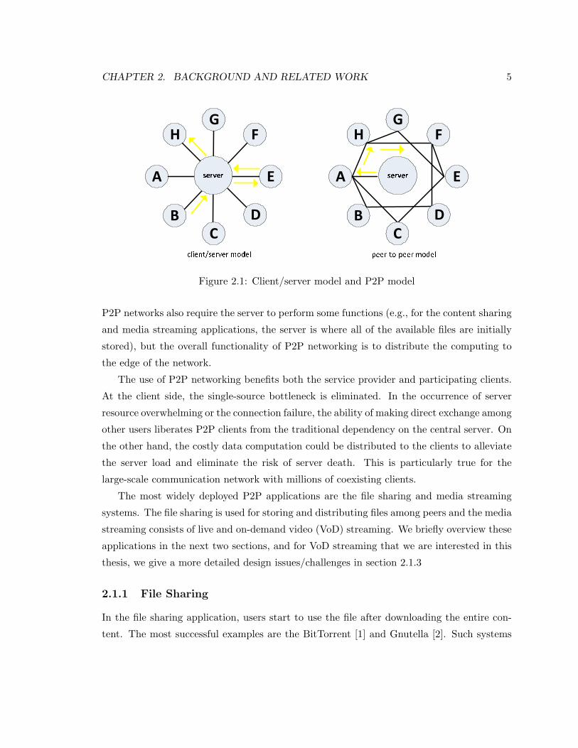
an architecture are storage, content sharing and media streaming. Figure 2.1 illustrates the
differences between client/server and P2P models. As we see that in client/server model,
all the communications are controlled and coordinated by the central server, while in P2P
model, communications go through and managed by peers directly. These exchanges include
the control messages (such as requests for information of the content and file, computation
to be performed, local knowledge to be distributed) and the real data transmission. Most of
4
CHAPTER 2. BACKGROUND AND RELATED WORK 5
A
B D
C
F
E
G
H serverclient/server model serverpeer-to-peer modelA
B D
C
F
E
G
H
Figure 2.1: Client/server model and P2P model
P2P networks also require the server to perform some functions (e.g., for the content sharing
and media streaming applications, the server is where all of the available files are initially
stored), but the overall functionality of P2P networking is to distribute the computing to
the edge of the network.
The use of P2P networking benefits both the service provider and participating clients.
At the client side, the single-source bottleneck is eliminated. In the occurrence of server
resource overwhelming or the connection failure, the ability of making direct exchange among
other users liberates P2P clients from the traditional dependency on the central server. On
the other hand, the costly data computation could be distributed to the clients to alleviate
the server load and eliminate the risk of server death. This is particularly true for the
large-scale communication network with millions of coexisting clients.
The most widely deployed P2P applications are the file sharing and media streaming
systems. The file sharing is used for storing and distributing files among peers and the media
streaming consists of live and on-demand video (VoD) streaming. We briefly overview these
applications in the next two sections, and for VoD streaming that we are interested in this
thesis, we give a more detailed design issues/challenges in section 2.1.3
2.1.1 File Sharing
In the file sharing application, users start to use the file after downloading the entire con-
tent. The most successful examples are the BitTorrent [1] and Gnutella [2]. Such systems
CHAPTER 2. BACKGROUND AND RELATED WORK 6
provide users with potentially unlimited storage capacity by taking advantage of the con-
tent redundancy. Basically, the resource of the file is originally located at some peers in the
application community, which is available to all of the participating users. Upon a user’s
request, the reference to the requested file will help the user find the resource peers from
whom it can then download the file from.
The key technical issues imposed in such systems are network bandwidth consumption,
security and fairness. The new demand of big object (e.g., the video, audio, software,
other documents) and increased perception quality (e.g., high definition video, 3D/multi-
view videos) requires much higher bandwidth consumption for downloading than traditional
small objects such as files and music clips. The security issue arises due to the anonymity of
participating users, and the unfairness comes from the existence of free riders, who utilize
the system resource to get benefits without any contribution. This will degrade system
scalability if a bunch of free riders exist. Some incentive mechanisms are developed to
encourage contribution based on a so-called ”tit-for-tat” strategy, which provides higher
downloading speed to peers who have more bandwidth contributed [38].
2.1.2 Live and On-Demand Streaming
The media streaming applications are classified into two categories, namely, the live (PPLive
[6], and UUSee [7]) and on-demand streaming (GridCast [12] and Vanderbilt VoD [11]). In
P2P live streaming, the video source is freshly generated at the server and simultaneously
streamed to current peers. This means that all peers are watching the same part of the video
at the same time. The common interest of peers will increase the video content overlap and
encourage resource sharing among them. However, this application comes across one more
challenge (besides those in the file sharing) of minimizing the streaming delay, specially
when millions of users request to join the system at a same very short time period (the
problem is known as ”flash crowd” [34]) since for live video streaming, failing to stream in
real time will annoy watching users (e.g., the live broadcast of World Cup).
Compared with file sharing and live streaming, VoD generally supports richer user in-
teractions, and users have limited content in common (since users can join in the system
at any time and watch any part of the video). P2P VoD thus faces much more challenges,
and existing solutions are yet to be perfected to compete with the conventional client/server
model. In particular, it is well-known that the startup delay of state-of-the-art P2P VoD
remains much longer than powerful client/server-based systems, particularly those with
CHAPTER 2. BACKGROUND AND RELATED WORK 7
Content Distribution Network (CDN) support. For example, for the on-demand mode in
PPLive, the startup delays are often longer than 10 seconds, and sometimes go beyond half
a minute, while the average delay of YouTube is about 6.5 seconds [47], though the latter
has already been ranked as a slow site. The situation is only getting worse when rich VCR
operations such as fast forward, rewind, and random seek are introduced.
2.1.3 Overlay Construction and Segment Scheduling
A P2P overlay network refers to an application-layer network consisting of all participating
peers as the network nodes. Each overlay link that connects two peers is a logical link that is
build on the top of the underlying physical network topology but not necessary depends on
it. Such overlays are used for indexing and peer discovery for the desired files. The overlay
construction can be classified into two categories, the structured overlay and unstructured
overlay according to how the peers in the overlay network are linked to each other. The
structured overlay enables a more structured pattern of the overlay link that allows peers to
efficiently issue a search to some peer that has the desired file. The typical construction is
the distributed hash table (DHT) indexing which uses a consistent hashing to allocate the
ownership of each file to some particular peers, see example systems Chord [50] and CAN
[46].
The unstructured overlay is however organized with overlay links arbitrarily established.
Such overlays are quite easy to be constructed upon a newly joining or a leaving peer,
e.g., when a peer firstly joins the overlay, it can directly fetch the overlay links from some
existing peers, and when a peer leaves, it can simply delete its owning links without any
influence on the remaining network. When a peer searches some file, it has to distribute
the query in a flooding fashion until the desired file is located. Such an operation is quite
costly for the rare content or the search could be highly possible to be unsuccessful when
the content is only shared by few peers in the overlay since no correlation between the file
and the peer is managed by any mechanism. Besides, the flooding can further increase
the traffic throughout the overlay and thus decrease the bandwidth utilization. Although
the structured P2P overlay provides efficient locating for both the popular and rare files,
it introduces significantly higher maintenance overhead than the unstructured overlay for
the popular contents. This is the main reason why the unstructured overlay is more widely
used over the Internet today. A more detailed and complete survey of the structured and
unstructured overlays is presented in [39].
CHAPTER 2. BACKGROUND AND RELATED WORK 8servertree-basedA BC D E F server
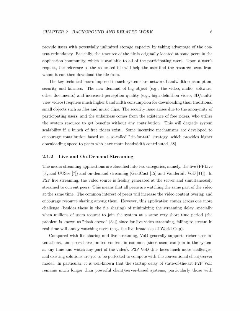
mesh-basedA BC D E FFigure 2.2: Tree-based and mesh-based data dissemination
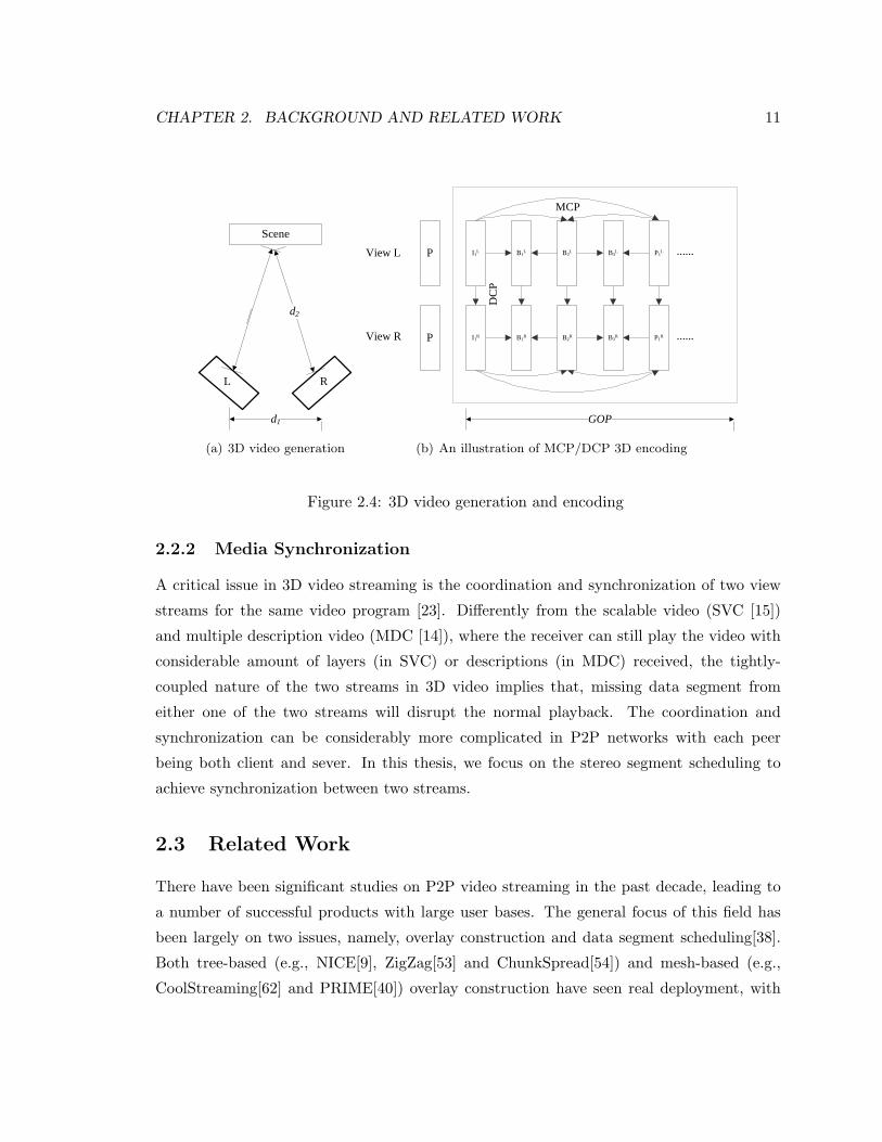
In the unstructured overlays, there are two categories of approaches for data dissemi-
nation, namely tree-based and mesh-based (as illustrated in Figure 2.2), see the review in
[38]. In the tree-based approach, peers are organized into one tree or multiple trees, with
each data packet being disseminated through them. Peers in the tree(s) have well-defined
relationship (i.e., parent-children relationship), where upon receiving one packet, the peer
will forward the copies of the packet to all its children (called Push operation). Since all
the data packets follow the same dissemination pattern, the tree(s) can be optimized to
guarantee good streaming performance. However, as the majority of the peers reside in the
leaves of the tree, their upload resources are not utilized efficiently. Further, such tree(s)
are fragile particularly when a peer higher in the tree leaves or fails, it may disrupt delivery
of data to a large number of offspring peers. To improve the resilience of the data delivery,
the mesh-based approach is proposed, where no specific structure of date delivery is de-
fined. Instead, peers randomly select some other peers to establish partnership to transmit
data. The data transmitted is also determined by the receiving peer, which we refer this
as data-driven or receiver-driven approach. The peer then fetches the desired data (called
Pull operation) from partners according to the scheduling mechanism.
When the partnership is established, the scheduling algorithm is to determine which
data segment should be fetched from which partner. The real time constraints in the media
streaming applications imply that the data segments must be obtained in a timely manner,
which thus requires the scheduling to fetch data segments from partners to meet their
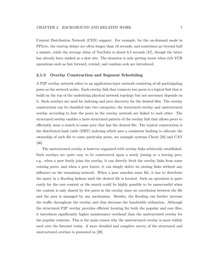
playback deadlines. Figure 2.3 shows the basic scheduling scheme for peer D in Figure
2.2, where a sliding buffer window is maintained, which indicates local segment availability
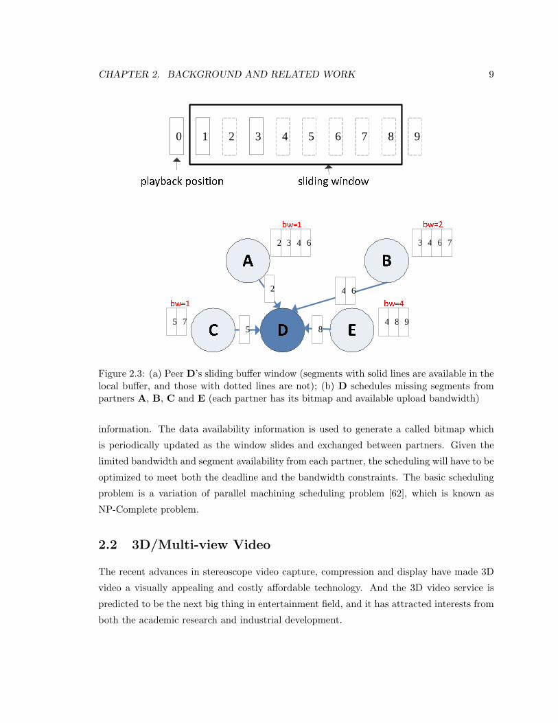
CHAPTER 2. BACKGROUND AND RELATED WORK 9
0 4playback position1 53 6 7 8 9sliding windowA BC D Ebw=12
2 3 4 6
bw=23 4 6 7bw=1
5 7
bw=44 8 9
2 4 6
85
Figure 2.3: (a) Peer D’s sliding buffer window (segments with solid lines are available in thelocal buffer, and those with dotted lines are not); (b) D schedules missing segments frompartners A, B, C and E (each partner has its bitmap and available upload bandwidth)
information. The data availability information is used to generate a called bitmap which
is periodically updated as the window slides and exchanged between partners. Given the
limited bandwidth and segment availability from each partner, the scheduling will have to be
optimized to meet both the deadline and the bandwidth constraints. The basic scheduling
problem is a variation of parallel machining scheduling problem [62], which is known as
NP-Complete problem.
2.2 3D/Multi-view Video
The recent advances in stereoscope video capture, compression and display have made 3D
video a visually appealing and costly affordable technology. And the 3D video service is
predicted to be the next big thing in entertainment field, and it has attracted interests from
both the academic research and industrial development.
CHAPTER 2. BACKGROUND AND RELATED WORK 10
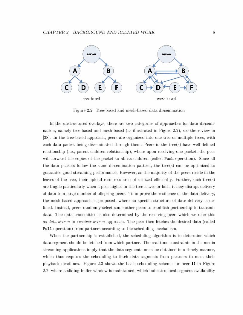
3D video is perceived by human beings with an additional three-dimensional depth,
which results from two spatial disparity of two views, each presenting the view of one
eye (Figure 2.4(a)). The multi-view video, on the other hand, enables multiple positions
of watching the same video. This allows the viewer select or change the preferred view
position to enjoy the video, not necessary in the front middle of the screen. Each view
position provides either the traditional monoscope perception or possible stereo perception
from adjacent two views [27]. In the following sections, we present an overview of the
generation, encoding/decoding and display technologies for the two applications and the
streaming challenges, in particular, the media synchronization between two view streams.
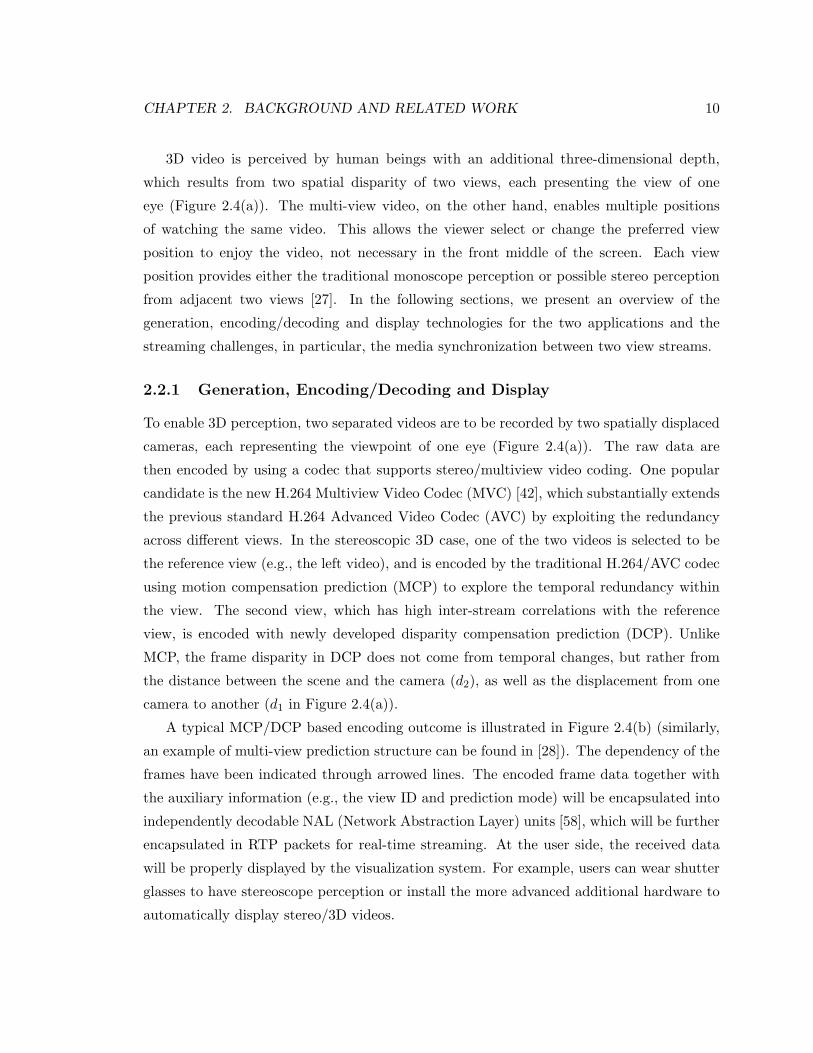
2.2.1 Generation, Encoding/Decoding and Display
To enable 3D perception, two separated videos are to be recorded by two spatially displaced
cameras, each representing the viewpoint of one eye (Figure 2.4(a)). The raw data are
then encoded by using a codec that supports stereo/multiview video coding. One popular
candidate is the new H.264 Multiview Video Codec (MVC) [42], which substantially extends
the previous standard H.264 Advanced Video Codec (AVC) by exploiting the redundancy
across different views. In the stereoscopic 3D case, one of the two videos is selected to be
the reference view (e.g., the left video), and is encoded by the traditional H.264/AVC codec
using motion compensation prediction (MCP) to explore the temporal redundancy within
the view. The second view, which has high inter-stream correlations with the reference
view, is encoded with newly developed disparity compensation prediction (DCP). Unlike
MCP, the frame disparity in DCP does not come from temporal changes, but rather from
the distance between the scene and the camera (d2), as well as the displacement from one
camera to another (d1 in Figure 2.4(a)).
A typical MCP/DCP based encoding outcome is illustrated in Figure 2.4(b) (similarly,
an example of multi-view prediction structure can be found in [28]). The dependency of the
frames have been indicated through arrowed lines. The encoded frame data together with
the auxiliary information (e.g., the view ID and prediction mode) will be encapsulated into
independently decodable NAL (Network Abstraction Layer) units [58], which will be further
encapsulated in RTP packets for real-time streaming. At the user side, the received data
will be properly displayed by the visualization system. For example, users can wear shutter
glasses to have stereoscope perception or install the more advanced additional hardware to
automatically display stereo/3D videos.
CHAPTER 2. BACKGROUND AND RELATED WORK 11
Scene
d1
d2
L R
(a) 3D video generation
I1L P1
LB3LB2
LB1L
I1R P1
RB3RB2
RB1R
P
P
GOP
......
......
View L
View R
MCP
DC
P
(b) An illustration of MCP/DCP 3D encoding
Figure 2.4: 3D video generation and encoding
2.2.2 Media Synchronization
A critical issue in 3D video streaming is the coordination and synchronization of two view
streams for the same video program [23]. Differently from the scalable video (SVC [15])
and multiple description video (MDC [14]), where the receiver can still play the video with
considerable amount of layers (in SVC) or descriptions (in MDC) received, the tightly-
coupled nature of the two streams in 3D video implies that, missing data segment from
either one of the two streams will disrupt the normal playback. The coordination and
synchronization can be considerably more complicated in P2P networks with each peer
being both client and sever. In this thesis, we focus on the stereo segment scheduling to
achieve synchronization between two streams.
2.3 Related Work
There have been significant studies on P2P video streaming in the past decade, leading to
a number of successful products with large user bases. The general focus of this field has
been largely on two issues, namely, overlay construction and data segment scheduling[38].
Both tree-based (e.g., NICE[9], ZigZag[53] and ChunkSpread[54]) and mesh-based (e.g.,
CoolStreaming[62] and PRIME[40]) overlay construction have seen real deployment, with
CHAPTER 2. BACKGROUND AND RELATED WORK 12
mesh-based overlay being particularly popular among industrial products given its simplicity
and robustness. Later works (e.g., [55], [54]) also seek hybrid designs that leverage the
advantages of both.
Given an overlay structure, scheduling algorithms for each peer’s buffer are then in-
voked to maximize the data delivering quality, particularly for mesh overlays with multiple
neighboring peers. Work in [37] did a measurement-based study on random scheduling, and
compared diverse elaborate and native scheduling schemes. A queue-based chunk schedul-
ing strategy was then developed for live video streaming, which achieved a near-optimal
streaming rate [16]. To enable efficient scheduling for both live and on-demand streaming, a
more recent work was presented in [19], which theoretically formulated the scheduling prob-
lem, together with an approximation algorithm that maximizes the perceived video quality.
Later ongoing efforts (e.g., [13] and [60]) further differentiated the strategies for data in a
zone-based fashion. These previous works however considered scheduling the conventional
single-view 2D video only. To our knowledge, P2P 3D video streaming has been largely un-
explored. There have been a few related works for P2P streaming of other 3D contents, e.g.,
for virtual world [20] [51] [21]. A close work to multi-view video is [31], where video streams
of multiple views are delivered over independent trees. We on the other hand considers the
more practical mesh-based solution with a focus on the stereo segment scheduling to deliver
different views.
With the recently advances in stereoscopic coding and displaying, 3D video streaming has
received remarkable attention, too. A basic layered architecture of streaming stereoscopic
videos over IP networks was outlined in [44]. To accommodate users with heterogeneous
displays, a content-adaptive stereo video coding and streaming framework was presented
in [8]. User interactivities in the multicast environment has also been examined in [29].
A critical issue in 3D video streaming is the coordination and synchronization of multiple
streams for the same video program [23]. An early work in [43] presented a protocol for
bandwidth aggregation and state exchange across multiple streams of a 3D video. It was
later enhanced in [61] [59] through exploring semantic redundancies among multiple related
streams, which better adapts to network dynamics. End-to-end rate-distortion optimization
has been examined [52] through estimating both the data importance and the network link
conditions. All the above works have relied on the classical client/server architecture, which
is known to be non-scalable and the the sheer volume of 3D video data further aggravates the
problem. Our focus is on P2P streaming, which we believe is a promising scalable solution
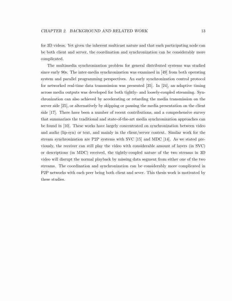
CHAPTER 2. BACKGROUND AND RELATED WORK 13
for 3D videos. Yet given the inherent multicast nature and that each participating node can
be both client and server, the coordination and synchronization can be considerably more
complicated.
The multimedia synchronization problem for general distributed systems was studied
since early 90s. The inter-media synchronization was examined in [49] from both operating
system and parallel programming perspectives. An early synchronization control protocol
for networked real-time data transmission was presented [35]. In [24], an adaptive timing
across media outputs was developed for both tightly- and loosely-coupled streaming. Syn-
chronization can also achieved by accelerating or retarding the media transmission on the
server side [25], or alternatively by skipping or pausing the media presentation on the client
side [17]. There have been a number of recent contributions, and a comprehensive survey
that summarizes the traditional and state-of-the-art media synchronization approaches can
be found in [10]. These works have largely concentrated on synchronization between video
and audio (lip-syn) or text, and mainly in the client/server context. Similar work for the
stream synchronization are P2P systems with SVC [15] and MDC [14]. As we stated pre-
viously, the receiver can still play the video with considerable amount of layers (in SVC)
or descriptions (in MDC) received, the tightly-coupled nature of the two streams in 3D
video will disrupt the normal playback by missing data segment from either one of the two
streams. The coordination and synchronization can be considerably more complicated in
P2P networks with each peer being both client and sever. This thesis work is motivated by
these studies.
Chapter 3
P2P 3D/Mulit-view Streaming
System
In this chapter, we present our peer-to-peer streaming system for 3D/multi-view videos. We
start with an overview of our system model for 3D/stereo videos, and detail the design in the
following two sections. In particular, we focus on the stereo segment scheduler design, where
we mathematically formulate the scheduling problem and propose efficient algorithms. We
will present extension of our design to support multi-view videos in Section 3.4 and some
discussion in Section 3.5.
3.1 System Model
While existing 3D video streaming systems are generally client/server based, this conven-
tional architecture has already suffered from streaming traffic-intensive 2D videos, and the
remarkably increased data volume of 3D video poses even greater challenges. Peer-to-peer
streaming, on the other hand, has shown to be a highly scalable and practical alternative.
We believe that it can be a candidate of great potentials for 3D video streaming, too, par-
ticularly considering that its commercial success in delivering live TV or on-demand movies,
and many these contents are in the transition from 2D to 3D.
We advocate a mesh-based P2P streaming system, which has been widely used in state-
of-the-art commercial systems [62] [6]. Each newly joined client (peer) will be informed
with a list of active peers interested in the current video, and it will randomly select some
14
CHAPTER 3. P2P 3D/MULIT-VIEW STREAMING SYSTEM 15
of them to establish partnerships. It will then exchange bandwidth and data availability
information with these partners and fetch video data through a scheduler, which specifies
each partner to transmit which segments. The active peer list will be periodically gossiped
through the overlay, so that existing peers can update their partners to accommodate peer
and network dynamics and possibly achieve better streaming performance.
Differently from traditional monoscopic 2D video streaming, two distinct data sequences
for a 3D video will be distributed, which are correspondingly produced by the encoded left
and right views. Data segments with the same playback time, upon receiving, will be
combined to produce a stereo frame pair, enabling depth perception. To ensure that the
segments of different views arrive simultaneously at a destination, a simple approach would
be mixing the segments into one streaming for transmission. It is however quite inflexible,
and we instead suggest that the segments being delivered through two separate streams. A
salient advantage here is the better compatibility and interoperability with monoscopic-only
clients, since only one of the two streams is needed given the client’s bandwidth or display
device constraints. This is necessary for a smooth and therefore successful transition to
3D video from the current hardware and software platforms that remain dominated by 2D
video.
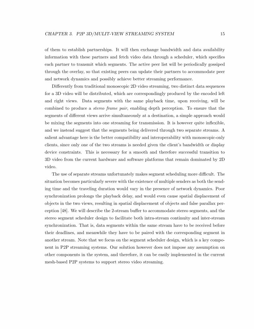
The use of separate streams unfortunately makes segment scheduling more difficult. The
situation becomes particularly severe with the existence of multiple senders as both the send-
ing time and the traveling duration would vary in the presence of network dynamics. Poor
synchronization prolongs the playback delay, and would even cause spatial displacement of
objects in the two views, resulting in spatial displacement of objects and false parallax per-
ception [48]. We will describe the 2-stream buffer to accommodate stereo segments, and the
stereo segment scheduler design to facilitate both intra-stream continuity and inter-stream
synchronization. That is, data segments within the same stream have to be received before
their deadlines, and meanwhile they have to be paired with the corresponding segment in
another stream. Note that we focus on the segment scheduler design, which is a key compo-
nent in P2P streaming systems. Our solution however does not impose any assumption on
other components in the system, and therefore, it can be easily implemented in the current
mesh-based P2P systems to support stereo video streaming.
CHAPTER 3. P2P 3D/MULIT-VIEW STREAMING SYSTEM 16
WuViewpoint Vu+1
playback point=0
one Playback Unit (PU)Viewpoint Vu(a) (b)
LR status 1
status 2 status 3
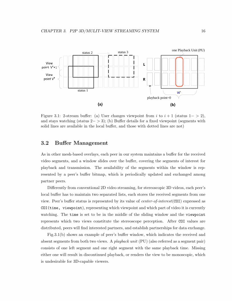
Figure 3.1: 2-stream buffer: (a) User changes viewpoint from i to i + 1 (status 1− > 2),and stays watching (status 2− > 3); (b) Buffer details for a fixed viewpoint (segments withsolid lines are available in the local buffer, and those with dotted lines are not)
3.2 Buffer Management
As in other mesh-based overlays, each peer in our system maintains a buffer for the received
video segments, and a window slides over the buffer, covering the segments of interest for
playback and transmission. The availability of the segments within the window is rep-
resented by a peer’s buffer bitmap, which is periodically updated and exchanged among
partner peers.
Differently from conventional 2D video streaming, for stereoscopic 3D videos, each peer’s
local buffer has to maintain two separated lists, each stores the received segments from one
view. Peer’s buffer status is represented by its value of center-of-interest(COI) expressed as
COI(time, viewpoint), representing which viewpoint and which part of video it is currently
watching. The time is set to be in the middle of the sliding window and the viewpoint
represents which two views constitute the stereoscope perception. After COI values are
distributed, peers will find interested partners, and establish partnerships for data exchange.
Fig.3.1(b) shows an example of peer’s buffer window, which indicates the received and
absent segments from both two views. A playback unit (PU) (also referred as a segment pair)
consists of one left segment and one right segment with the same playback time. Missing
either one will result in discontinued playback, or renders the view to be monoscopic, which
is undesirable for 3D-capable viewers.
CHAPTER 3. P2P 3D/MULIT-VIEW STREAMING SYSTEM 17
1 2
1 2
1 2
1 21
1 2
21
sender receiver
1 22
sender receiver
3
1 2 3
1 2 3
1 2 3
2 3
2 3
1 3
1 2
1
1
3
2
1 2
2
2
1 21
1 2
2
sender receiver
1
1
1
1 2
1 2
deadline/synchronization first
deadline first, two PUs are wasted
synchronization first, one PU is useful
Which one is preferred?
(a)
(b)
(c)
Figure 3.2: Cases of 2-stream buffer scheduling
CHAPTER 3. P2P 3D/MULIT-VIEW STREAMING SYSTEM 18
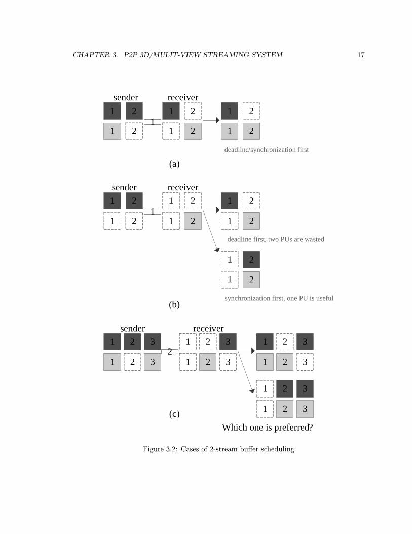
Figure 3.2 shows an example of the difficulty of stereo segment scheduling (with coex-
istence of playback deadline, limited bandwidth, availability and stream synchronization)
with the 2-stream buffer, where the peer receiver has only one sender. The dark grey seg-
ments are from stream 1 and the light grey ones are from stream 2. The blank ones are
missing segments. There are links between sending and receiving peers with a number on
it, indicating the uploading bandwidth (or the maximum number of segments that can be
transmitted within one time slot).
• In case (a), only one segment can be transmitted. Obviously, segment1 from stream2
should be fetched for it has earlier deadline, and also it can compose a complete PU.
• In case (b) with the same available bandwidth, there are however two options, as
shown in Figure 3.2. The second one is preferred since there will be at least one PU
useful, although it does not obey deadline-first.
• A more complicated situation is shown in case (c). In the first option, the scheduler
fetches the two segments with the earliest deadlines, which also constitute a useful
PU, while in the second option, it selects later segments but can obtain two useful
PUs.
The question arises: which one should the scheduler prefer, deadline first with fewer
useful PU or more complete PUs with urgent segments left missing? The situation could be
further complicated when more senders are involved.
3.3 Stereo Segment Scheduling
We now mathematically formulate the stereo segment scheduling as an Binary Quadratic
Programming problem, and show its hardness. We will present the two proposed algorithms
to achieve efficient scheduling, followed by the algorithm analysis.
3.3.1 Problem Statement
Let PUu denote the set of PUs to be scheduled for u (since peers only schedule segments
within the buffer window, the maximum number of PUs equals peer’s window size, which
is W u). Let wi denote the weight of the ith PU and O be u’s partner set (|O| = M). We
use V u to denote u’s views set, V u = {Lu, Ru}, meaning that u’s stereoscope viewpoint is
CHAPTER 3. P2P 3D/MULIT-VIEW STREAMING SYSTEM 19
composed of the left view Lu and the right view Ru. The segment availability in partner m
is represented by amiku , ku ∈ V u, indicating whether m has buffered the ith segment of stream
ku (with amiku = 1 being yes). Let bmu denote m’s bandwidth allocated to u. In our system,
each partner will evenly allocate its total bandwidth to all its receiving peers for fairness.
Let xmiku denote the scheduling variable, representing whether fetching the ith segment of
stream ku from m or not. We formulate the stereo segment scheduling problem as follows:
Max.∑
i∈PUu
wi
∏ku∈V u
xiku (3.1)
s.t. xiku =∑m∈O
xmiku + auiku (3.2)
xmiku ≤ amiku , ku ∈ V u (3.3)∑ku∈V u
∑i∈PUu
xmiku ≤ bmu (3.4)
∑m∈O
xmiku ≤ 1 (3.5)
xmiku , amiku ∈ {0, 1} (3.6)
The objective function is to maximize the weighted number of complete PUs. The weight
wi could be modeled as the importance of the ith PU (e.g., video quality improvement, the
decoding role it takes, or the urgent level it lies (deadline related)). We will discuss the
weight modeling issues in Discussion Section. The first constraint means that any segment
is only available if at least one of the partners send it to u, or u has already locally buffered
it. The second constraint implies that whether the sending partner m has a copy of this
segment or not. The third constraint indicated the bandwidth limitation. Note that bmu is
represented by the number of segments. This is an approximated value since segments have
different sizes. However, upon receiving transmission requests, partners will send segments
until total bandwidth is used up. The fourth constraint is to avoid duplicated transmission
from multiple partners.
Problem Hardness and the Optimal Solution: The stated stereo segment schedul-
ing is Binary Quadratic Programming (BQP) problem, which is known to be NP-Hard [26].
Many existing solvers are developed to optimally solve these problems. In this thesis, we
implement the MIQP solver in CPLEX [3] package to get the optimal scheduling (referred
as OPT algorithm), serving as the benchmark for performance comparison.
CHAPTER 3. P2P 3D/MULIT-VIEW STREAMING SYSTEM 20
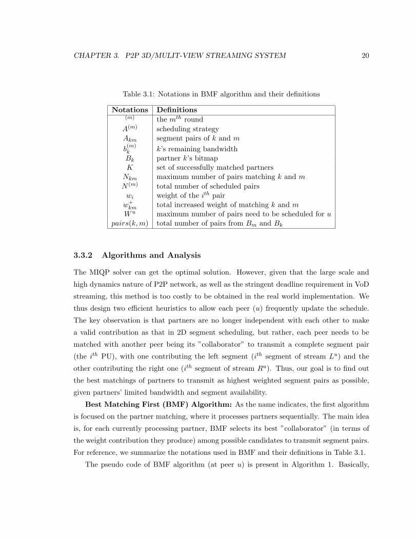
Table 3.1: Notations in BMF algorithm and their definitions
Notations Definitions(m) the mth round
A(m) scheduling strategyAkm segment pairs of k and m
b(m)k k’s remaining bandwidthBk partner k’s bitmapK set of successfully matched partners
Nkm maximum number of pairs matching k and m
N (m) total number of scheduled pairswi weight of the ith pairw+km total increased weight of matching k and m
W u maximum number of pairs need to be scheduled for upairs(k,m) total number of pairs from Bm and Bk
3.3.2 Algorithms and Analysis
The MIQP solver can get the optimal solution. However, given that the large scale and
high dynamics nature of P2P network, as well as the stringent deadline requirement in VoD
streaming, this method is too costly to be obtained in the real world implementation. We
thus design two efficient heuristics to allow each peer (u) frequently update the schedule.
The key observation is that partners are no longer independent with each other to make
a valid contribution as that in 2D segment scheduling, but rather, each peer needs to be
matched with another peer being its ”collaborator” to transmit a complete segment pair
(the ith PU), with one contributing the left segment (ith segment of stream Lu) and the
other contributing the right one (ith segment of stream Ru). Thus, our goal is to find out
the best matchings of partners to transmit as highest weighted segment pairs as possible,
given partners’ limited bandwidth and segment availability.
Best Matching First (BMF) Algorithm: As the name indicates, the first algorithm
is focused on the partner matching, where it processes partners sequentially. The main idea
is, for each currently processing partner, BMF selects its best ”collaborator” (in terms of
the weight contribution they produce) among possible candidates to transmit segment pairs.
For reference, we summarize the notations used in BMF and their definitions in Table 3.1.
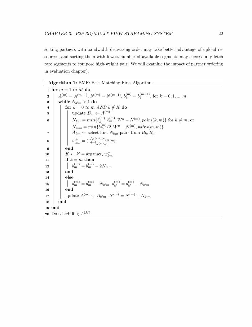
The pseudo code of BMF algorithm (at peer u) is present in Algorithm 1. Basically,
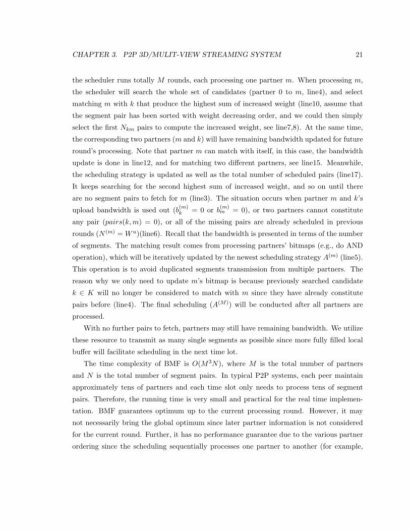
CHAPTER 3. P2P 3D/MULIT-VIEW STREAMING SYSTEM 21
the scheduler runs totally M rounds, each processing one partner m. When processing m,
the scheduler will search the whole set of candidates (partner 0 to m, line4), and select
matching m with k that produce the highest sum of increased weight (line10, assume that
the segment pair has been sorted with weight decreasing order, and we could then simply
select the first Nkm pairs to compute the increased weight, see line7,8). At the same time,
the corresponding two partners (m and k) will have remaining bandwidth updated for future
round’s processing. Note that partner m can match with itself, in this case, the bandwidth
update is done in line12, and for matching two different partners, see line15. Meanwhile,
the scheduling strategy is updated as well as the total number of scheduled pairs (line17).
It keeps searching for the second highest sum of increased weight, and so on until there
are no segment pairs to fetch for m (line3). The situation occurs when partner m and k’s
upload bandwidth is used out (b(m)k = 0 or b
(m)m = 0), or two partners cannot constitute
any pair (pairs(k,m) = 0), or all of the missing pairs are already scheduled in previous
rounds (N (m) = W u)(line6). Recall that the bandwidth is presented in terms of the number
of segments. The matching result comes from processing partners’ bitmaps (e.g., do AND
operation), which will be iteratively updated by the newest scheduling strategy A(m) (line5).
This operation is to avoid duplicated segments transmission from multiple partners. The
reason why we only need to update m’s bitmap is because previously searched candidate
k ∈ K will no longer be considered to match with m since they have already constitute
pairs before (line4). The final scheduling (A(M)) will be conducted after all partners are
processed.
With no further pairs to fetch, partners may still have remaining bandwidth. We utilize
these resource to transmit as many single segments as possible since more fully filled local
buffer will facilitate scheduling in the next time lot.
The time complexity of BMF is O(M3N), where M is the total number of partners
and N is the total number of segment pairs. In typical P2P systems, each peer maintain
approximately tens of partners and each time slot only needs to process tens of segment
pairs. Therefore, the running time is very small and practical for the real time implemen-
tation. BMF guarantees optimum up to the current processing round. However, it may
not necessarily bring the global optimum since later partner information is not considered
for the current round. Further, it has no performance guarantee due to the various partner
ordering since the scheduling sequentially processes one partner to another (for example,
CHAPTER 3. P2P 3D/MULIT-VIEW STREAMING SYSTEM 22
sorting partners with bandwidth decreasing order may take better advantage of upload re-
sources, and sorting them with fewest number of available segments may successfully fetch
rare segments to compose high-weight pair. We will examine the impact of partner ordering
in evaluation chapter).
Algorithm 1: BMF: Best Matching First Algorithm
1 for m = 1 to M do
2 A(m) = A(m−1), N (m) = N (m−1), b(m)k = b
(m−1)k , for k = 0, 1, ...,m
3 while Nk′m > 1 do4 for k = 0 to m AND k ∈ K do
5 update Bm ← A(m)
6 Nkm = min{b(m)k , b
(m)m ,W u −N (m), pairs(k,m)} for k = m, or
Nmm = min{b(m)m /2,W u −N (m), pairs(m,m)}
7 Akm ← select first Nkm pairs from Bk, Bm
8 w+km =
∑iN(m)+Nkmi=i
N(m)+1wi
9 end10 K ← k′ = argmaxk w
+km
11 if k = m then
12 b(m)m = b
(m)m − 2Nmm
13 end14 else
15 b(m)m = b
(m)m −Nk′m, b
(m)k′ = b
(m)k′ −Nk′m
16 end
17 update A(m) ← Ak′m, N (m) = N (m) +Nk′m
18 end
19 end
20 Do scheduling A(M)
CHAPTER 3. P2P 3D/MULIT-VIEW STREAMING SYSTEM 23
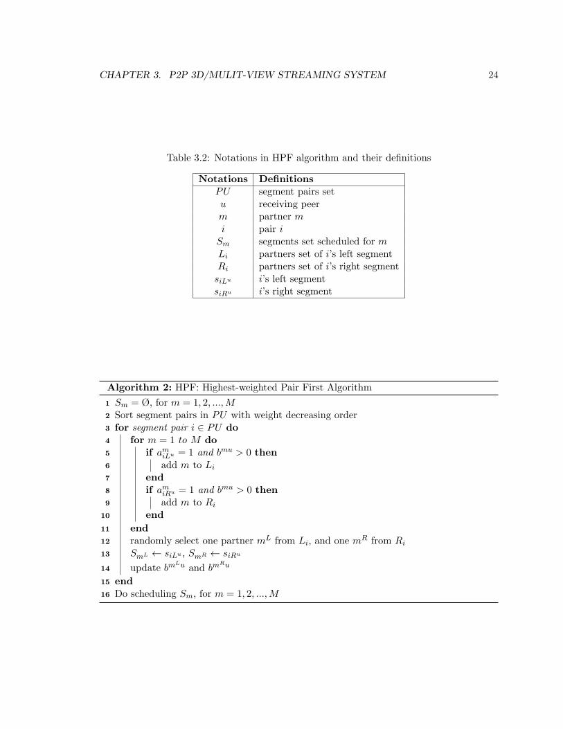
Highest-weighted Pair First (HPF) Algorithm: Differently from BMF, HPF pro-
cesses segment pairs sequentially, starting from the pair with the highest weight and then
the second highest and so on. As in Algorithm 2, we firstly sort all possible W u segment
pairs in weight decreasing order (line2). And for each segment pair i, the HPF scheduler
will find two partners sets that can transmit i’s left segment and right segment respectively
(line6,9). Then it randomly selects two partners (mL and mR), each from one set, that can
collaboratively transmit a complete pair (line12) and schedule the corresponding segments
to the two partners (line13). Meanwhile, their remaining bandwidth are updated (line14).
Similarly, the scheduler stops when all of the required segment pairs are scheduled or any
two of the partners can not transmit a whole pair (either they have no remaining bandwidth
or they do not cache the segments in their local buffers), and does the scheduling (line16).
In the following theorem, we prove that the proposed HPF algorithm has an approximation
factor of 3 for the stereo segment scheduling problem.
THEOREM 1. HPF has an approximation factor of 3 for the stereo segment scheduling
Proof. Let P be the set of segment pairs scheduled by our algorithm and P ∗ be the optimal
solution. Correspondingly, W (P ) is the total weight value HPF generates and W (P ∗) is the
optimal value. We define S = P∩P ∗, T = P \ S and T ∗ = P ∗ \ S. Therefore, we have
P ∗ = S∪T ∗, where S ⊆ P . For each segment pair i∗ ∈ T ∗, which is scheduled to fetch from
partner m∗i and n∗
i in the optimal solution, the reason why our algorithm does not schedule
it is because at least one of m∗i and n∗
i has no remaining bandwidth (line5,8) when we are
trying to schedule this pair (since it is in the optimal solution, the two partners do have
cached the corresponding segments). Thus, the last remaining bandwidth of m∗i or/and n∗
i
must be used in some previous round in HPF to fetch another segment pair, say j(i∗). By
our algorithm (line2,3), the weight value produced by pair j(i∗) is higher than i∗, that is,
wi∗ ≤ wj(i∗). Note that j(i∗) could be in S. This case happens when HPF chooses two
wrong partners (at least one of them are either m∗i or n∗
i ) to fetch it due to the random
partner selection (line12), resulting in this partner’s bandwidth unable to be used to fetch
later segment pair. Thus, we have j(i∗) ∈ P . Note that for different i∗, we may have
the same j(i∗), however the number of copies of the same j(i∗) is at most two since only
two bandwidth is needed to fetch one pair, which implies that∑
wj(i∗) ≤ 2∑
wj , j ∈ P .
Therefore, W (P ∗) = W (S)+W (T ∗) = W (S)+∑
wi∗ ≤W (S)+∑
wj(i∗) ≤W (P )+2∑
wj ≤W (P ) + 2W (P ) = 3W (P ).
CHAPTER 3. P2P 3D/MULIT-VIEW STREAMING SYSTEM 24
Table 3.2: Notations in HPF algorithm and their definitions
Notations DefinitionsPU segment pairs setu receiving peerm partner mi pair i
Sm segments set scheduled for mLi partners set of i’s left segmentRi partners set of i’s right segmentsiLu i’s left segmentsiRu i’s right segment
Algorithm 2: HPF: Highest-weighted Pair First Algorithm
1 Sm = Ø, for m = 1, 2, ...,M2 Sort segment pairs in PU with weight decreasing order3 for segment pair i ∈ PU do4 for m = 1 to M do5 if amiLu = 1 and bmu > 0 then6 add m to Li
7 end8 if amiRu = 1 and bmu > 0 then9 add m to Ri
10 end
11 end12 randomly select one partner mL from Li, and one mR from Ri
13 SmL ← siLu , SmR ← siRu
14 update bmLu and bm
Ru
15 end16 Do scheduling Sm, for m = 1, 2, ...,M
CHAPTER 3. P2P 3D/MULIT-VIEW STREAMING SYSTEM 25
UC HB E FA D G Playback TimeV
iew
poin
tsVuVu-1Vu+1 Priority LineWu
k-nearest neighborhoodTu
Figure 3.3: V-Plane Overlay: U has direct partners C in its priority line, and indirectpartners B,D,E in its k-nearest neighborhood
The time complexity of HPF is O(MN), where M is the total number of partners and N
is the total number of segment pairs. Similarly as stated previously, as each peer maintain
approximately tens of partners and each time slot only needs to process tens of segment pairs.
Therefore, the running time is also very small. Further, HPF scheduler have partners load
reasonably balance due to the randomness of selecting partners among possible candidates
to transmit segments.
3.4 Extension to Multi-view
In this section, we implement our segment stereo scheduler in multi-view scenario to verify
its feasibility, where to support multi-view with view diversity and dynamics, a light-weight
clustering based overlay will be introduced.
To realize multi-view video, multiple cameras that are spatially displaced record the
same video from one different angle, each representing a 2D viewing position. This allows
users to arbitrarily select one viewpoint to enjoy the video, not necessary to be on a fixed
position in the middle front of the screen. Further, users can possibly have 3D perception
CHAPTER 3. P2P 3D/MULIT-VIEW STREAMING SYSTEM 26
from two adjacent views in multiple different viewing positions, which we are interested in
the thesis.
In this multi-view scenario, not only a user might be interested in different part of a
video, but also might prefer to watch the video from different angles as well. This constrains
resource sharing among peers. Besides the view diversity, users may change viewpoint during
watching. Some pioneer work address this problem by view prediction from users feedback
in clinet/server streaming. This is however computationally costly given the co-existence of
millions of users as well as frequent view changes.
We address these challenges by leveraging clustering (in particular, Voronoi diagram [33])
to efficiently locate partners with same/overlapped interest. As in Fig.3.3, we use Voronoi
diagram as a virtual plane (called V-Plane) that extends in time and space dimensions. The
space dimension consists of discrete viewpoints, each representing a 3D perception of two
adjacent views. The time dimension then corresponds to playback time slots. As such, each
peer can be located at one point in the V-Plane according to its COI value (recall that the
COI is the center of peer’s interest, expressed as COI(time, viewpoint)). We can see that,
although peers have individually-differentiated COI, they can still have overlapped content
of interest. This is because peers are usually interested in video content in a period of time,
which locate near its COI (in the time scale). Further, adjacent peers will have one same
view shared (in the space scale). As an example, peer A with COI(3,1) and peer B with
COI(4,2) both are interested in video segments playing at time 3 and 4 in view 2 (consider
the buffer window of size 3).
In V-Plane, peers having overlapped interest are partners. Each peer maintains two
partners lists, namely, direct partners (DP) and indirect partners (uDP). The DP list consists
of partners that are watching at the same viewpoint and are within the interest time period
(in peer’s priority line, Fig.3.3), while the uDP list has partners locating at farther range
(in peer’s k-nearest neighborhood). Although the indirect partners may not exchange the
current video content, they could be possibly promoted to be direct partners, especially
when the peer changes viewpoint or when it has insufficient number of direct partners. An
example of peer’s direct and indirect partners is shown in the figure.
Note that with view dynamics, the 2-stream buffer window will slide in both spatial
and temporal directions (Fig.3.1(a)). This means that in the case of view change, the
pre-downloaded content of the current viewpoint may not be useful while the new content
of interest has yet to be fetched. To avoid data outage, the V-Plane overlay reduces the
CHAPTER 3. P2P 3D/MULIT-VIEW STREAMING SYSTEM 27
view switching delay by quickly re-locating new partners; for example, when U changes
perception viewpoint, it can quickly locate new direct partners from its current uDP list
(since in the normal cases, peers will gradually change viewpoints, i.e., to its adjacent
viewpoint first). View dynamics also implies frequent updates of COI. This will however
introduce little computational overhead because, during the normal playback, both a peer
and its partners’ sliding windows are moving with the same speed (i.e., the video playback
speed). Therefore, the partnership is maintained and no update is needed. Further, there
is no data exchange between indirect partners, and thus, little more information (e.g., the
bitmap) need to be maintained.
3.5 Discussion
In this section, we will discuss the weight modeling of PUs (segment pairs) and implemen-
tation issues on inter-operability of 3D/multi-view video with existing 2D videos.
The weight of each PU is an important factor in stereo segment scheduling. We currently
integrate two factors to model the weight, namely, smoothness gain (SG) and quality gain
(QG). The SG contribution of the weight comes from the playback upon receiving the
complete PU, which is basically deadline-based. We model the smoothness gain as SG =
g(d), where d is the corresponding deadline and g is a monotonically decreasing function
since urgent segments would bring relatively better continuity. QG presents the quality
that PU brings. In video coding, a frame’s quality is typically evaluated by its PSNR
value. The computation of PSNR unfortunately requires full decoding of the received frame
and the knowledge of the original frame values, which are hardly available during real-
time streaming. The computation also involves intensive processing. Given that we are
interested in the relative ranking of each frame, we instead examine how much possible
quality degradation each frame would cause upon loss. A straightforward way is to use
the accumulated bits to represent the quality degradation of the frame (equally the frame
size), which we implemented in our scheduling for its simplicity and light computational
complexity.
There are many advanced quality degradation modelings in the literature that are based
on the distortion estimation upon frame loss, which considers both the decoding dependency
and networking congestion. There are many pioneer work on this field, as mentioned in
previous sections, state-of-the-art 3D encoding such as H.264 MVC explores both intra and
CHAPTER 3. P2P 3D/MULIT-VIEW STREAMING SYSTEM 28
inter view redundancy for compression. As such, the absence of a frame would render a
series of frames to undecodable should they use this frame as a reference, within or across
views. For example, in Figure 2.4(b), missing frame PL1 will affect frame BL
2 , BL3 and PR
1 ,
which will further affect the decoding of BR2 and BR
3 . A dependency List (DL) of PL1 can
be defined to represent these affected frames. Consider a typical error concealment scheme
upon loss, where the lost frame (say frame A) will be replaced by the previous successfully
received frame (say frame B), and frames belonging to A’s DL will also be replaced by B.
We will then have an absolute Difference Value (DV) for each frame, which is computed
as the sum of Mean Absolute Difference (MAD) of this frame and those in its dependency
list. That is, for the nth frame, we have DVn =∑M
m=1MADm,m ∈ DLn, where M is the
length of frame n’s DL. The DV value qualitatively characterizes the degradation upon loss
of the frame, or equivalent, the gain if it were not lost. Thus, we can model the quality
again for PU i being: QGi =∑M
m=1MADm,m ∈ DLn, i ∈ frame n. The QGi values can
be generated during encoding at the server side, and are then distributed from the server
to the whole overlay, so that all participating peers can have this knowledge for each PU.
A more accurate distortion estimation model is proposed in [57], given as Dc,n =
PDECP,n + α(βn, P )Dc,n−1. The distortion of frame n is recursively computed as the sum
of the concealment distortion in this frame and the channel distortion in the previous frame
by a factor of α, which depends on the network loss probability P and the inherent encod-
ing configuration βn, e.g., the intraprediction ratio within one frame and the de-blocking
filtering. This model considers the loss from the network congestion, the concealment error
from reconstructing of the current encoded frame, and the error propagation from previ-
ously related frames as well. And thus, it provides more accurate estimation with sacrifice
of increased computation cost since it requires per-pixel error computation and exploration
of slice construction inside the frame at the server side, and these information has to be
distributed among the whole network to allow local scheduling computation.
We now discuss some implementation issues on inter-operability of 3D/multi-view video
with existing 2D videos. As 3D video remains in its early stage, many of the existing client
video playback platforms support monoscopic 2D video only, even though a client may have
sufficient bandwidth to receiving 3D streams. On the other hand, some 3D-capable client
may want to disable it and instead have smoother 2D playback with less bandwidth demand.
We thus believe that it is necessary to accommodate these clients in our 3D streaming
system, so as to enable a smooth transition toward the full 3D peer-to-peer streaming.
CHAPTER 3. P2P 3D/MULIT-VIEW STREAMING SYSTEM 29
Our separate stream design well supports such a compatibility mode. A traditional 2D
client may simply fetch and playback one view only, and use extra bandwidth, if available,
to assist the streaming of another view. Note that, if the two views are independently
encoded, the client can arbitrarily choose one. For H.264 MVC-like encoding, however,
inter-view redundancy is explored and there is a reference view (MCP-coded) for decoding
of other views. In this case, the 2D client need to fetch and display this reference view
only. Alternatively, the client may fetch certain key frames from the reference view together
with DCP-coded frames from another view, so as to display another view only or alternate
between the two views. The latter is more flexible but involves more complicated data
scheduling. A further extension is to the multi-view (or free-viewpoint) video, where more
than two cameras record the same video from each different angle. This would allow users
to arbitrarily select one viewpoint of the screen to enjoy the video, not necessary to be
on a fixed viewing position in the middle front of the screen. It also enables stereoscopic
display without wearing special glasses. Our P2P streaming system is flexible in supporting
multi-view stereo streaming as stated previously. Nevertheless, given the high degree of
view diversity and dynamics, more advanced multi-view design (e.g., overlay construction,
partnership maintenance) are to be further developed.
Chapter 4
Evaluation
4.1 Simulation Setup
We evaluate the performance of our 3D/multi-view video streaming system through simu-
lations. Similar to [22], we generate three typical classes of peers, namely, Cable/Ethernet,
DSL2, and Modem/ISDN/DSL1. We summarize the bandwidth distribution and peer popu-
lation for each class in Table 4.1. Due to the existence of free riders in traditional peer-to-peer
systems, we assume that peers are willing to contribute approximately half of their resources
(download bandwidth) for sharing. As in previous studies [36] [56], we assume a Poisson
process with rate λ for peer arrival, and the default λ is set to 20, i.e., on average 20 peers
arrive every minute (we will examine the impact of peer arrival rate in later subsections).
We also use a Weibull distribution to model the lifetime of the participating peers [18]. As
such, the peers join the system at different times, and would stay throughout the simulation
(60 minutes) or depart earlier should a peer has a relatively short lifetime.
The video source we used for simulation is based on the standard multi-view video
sequence ”Ballet” (MERL [5]). The resolution is 1024*768 with a frame rate of 15 frames/s.
We select two views to construct a stereo video sequence of 120 seconds. Using the reference
JMVC 8.0 Encoder [4], adjacent two view video has an average bitrate of 746.4kbps, and
we repeat the sequence throughout the 1-hour simulation.
30
CHAPTER 4. EVALUATION 31
Table 4.1: Bandwidth capacity and peer distributionClass Population Download Upload
Cable/Ethernet 60% 3Mbps 1.5MbpsDSL2 20% 1.5Mbps 768Kbps
Modem/ISDN/DSL1 20% 768Kbps 384Kbps
4.2 3D Video Performance
In this Section, we consider a fixed viewpoint of 3D/stereo streaming. We firstly evaluate
the feasibility as well as the benefit of our proposed separate streaming system in 4.2.1.
Performance comparison between our proposed schedulers and the optimal scheduler, as
well as the state-of-the-art of existing schedulers is conducted in 4.2.3. Finally, we study
some impact factors on our scheduling algorithm in 4.2.4.
4.2.1 Sep-Streaming vs. Mix-Streaming
To evaluate our separated streaming, a typical P2P mesh for 2D video is implemented as
a baseline for comparison, where to accommodate 3D video, the two streams are simply
mixed together with a random scheduler (referred as MixR). Our separated streaming
also implements a random scheduler (referred as SepR). In both systems, buffer window
size is set to be 20 (in terms of the number of segments). Peers have the default arrival
rate (λ = 20). During streaming peers have totally eight serving partners, and upon bad
partners, peers would update partners list from server, and finally fail if no good partners
updated after several rounds unfortunately.
Figure 4.1(a) shows the average streaming rate of all active peers for the overlay of
different sizes. Note that we consider a dynamic system here. That is, the overlay size
will generally increase when time increases because of continuous new-coming and leaving
peers. When our simulation approaches the end (time=60min), we have more than 1000
active peers totally in the streaming overlay. We record the average rate at each simulation
minute, and plot sampled minutes in the Figure. As we stated in previous section, the
original video has a data rate of approximately 746.4kbps. We can see that there is a gap
between the original rate and both systems’. This is because we compute the average data
rate of all peers, which includes new joined peers (those are in the startup stage, and have
not received enough amount of data to begin playback) and failed peers (those have large
CHAPTER 4. EVALUATION 32
0 200 400 600 800 1000 1200550
600
650
700
750
Overlay Size (number of peers)
Ave
rage
Dat
a R
ate
(Kb/
s)
SepR
MixR
(a) Average data rate
0 10 20 30 40 50 600
10
20
30
40
50
60
70
80
90
100
Startup Delay (seconds)
CD
F o
f Sta
rtup
Del
ay (
%)
SepR
MixR
(b) Startup delay
0 0.2 0.4 0.6 0.8 10
10
20
30
40
50
60
70
80
90
100
Playback Continuity
CD
F o
f Pla
ybac
k C
ontin
uity
(%
)
Sep
R
MixR
(c) Playback continuity
400 500 600 700 800 900 1000 1100 12000
1
2
3
4
5
6
7
8
Overlay Size (number of peers)
Ave
rage
Loa
d on
Ser
vers
(%
)
SepR
MixR
(d) Server load
0 200 400 600 800 1000 12000
0.05
0.1
0.15
0.2
0.25
0.3
0.35
0.4
0.45
0.5
Overlay Size (number of peers)
Ave
rage
Per
−pe
er O
verh
ead
(%)
SepR
MixR
(e) Per-peer overhead
Figure 4.1: The feasibility and benefit of separate streaming
CHAPTER 4. EVALUATION 33
playback delays, and simply stuck during some playback position). Another reason for
the gap is the coexistence of peer bandwidth heterogeneity and content distribution. That
is, powerful peers may lack of available content while peers with rich content suffer from
bandwidth bottleneck. And thus, peer upload bandwidth (the average upload is 1152Kbps,
which can only reach 1.5 of the streaming rate) may not be fully utilized due to the poor
content distribution, which is known as a challenge in peer-to-peer networks (this discussion
is out of the scope of this thesis). As we will see later, the optimal scheduler can not
achieve the original streaming rate either. When the overlay becomes stable, Sep-streaming
performs better than Mix-streaming with a noticeable improvement (around 10Kbps). This
implies that our separated streaming design not only provides better streaming flexibility
but also comparable/higher streaming rate.
The cumulative distribution function (CDF) of the startup delay and playback continuity
are depicted in Figure 4.1(b) and Figure 4.1(c) respectively. In our simulation, the initial
buffering time is set to 10 seconds, i.e., a peer can only start playing videos after 10 seconds
of video segments are downloaded. We can see from the figure that MixR has approximately
50% peers have startup delay of less than 15 seconds. However, SepR reduces the delay to
10 seconds with the same peer population, which means that for those peers, they could
receive the first 10 seconds amount of data, and begin playback with 5 seconds less of the
time, which is noticeable during the buffering stage.
We also investigate the playback quality experienced by individual peers, particularly,
the continuity of the streaming playback as represented by the fraction of the on-time
segments [62]. In our comparison, these on-time segments not only need to catch up their
deadlines, but also, they have to be paired (or valid) as single left segment or single right
segment will fail to constitute a stereo perception (in the Mix-streaming case, received data
are all already valid). The CDF of playback continuity for all peers is plotted in Figure
4.1(c), which shows that, near 80% of the peers enjoy a continuity over 0.8 in MixR while
only 70% peers have the same continuity in SepR. However, SepR has more peers with
higher continuity (e.g., SepR has more than 60% peers with continuity of 0.96 while MixR
only have 35% peers achieving this level). The better performance of MixR in the lower
continuity range is because all received segments in Mix-streaming are considered to be
valid while in SepR, unsynchronized segments are regarded to be useless for continuity
improvement, which results in increased invalid segments (or worse playback continuity).
This implies that more advanced scheduling algorithm is to be developed to synchronize
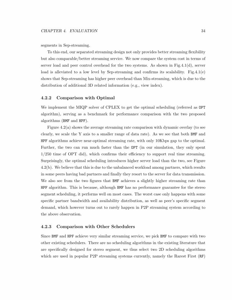
CHAPTER 4. EVALUATION 34
segments in Sep-streaming.
To this end, our separated streaming design not only provides better streaming flexibility
but also comparable/better streaming service. We now compare the system cost in terms of
server load and peer control overhead for the two systems. As shown in Fig.4.1(d), server
load is alleviated to a low level by Sep-streaming and confirms its scalability. Fig.4.1(e)
shows that Sep-streaming has higher peer overhead than Mix-streaming, which is due to the
distribution of additional 3D related information (e.g., view index).
4.2.2 Comparison with Optimal
We implement the MIQP solver of CPLEX to get the optimal scheduling (referred as OPT
algorithm), serving as a benchmark for performance comparison with the two proposed
algorithms (BMF and HPF).
Figure 4.2(a) shows the average streaming rate comparison with dynamic overlay (to see
clearly, we scale the Y axis to a smaller range of data rate). As we see that both BMF and
HPF algorithms achieve near-optimal streaming rate, with only 10Kbps gap to the optimal.
Further, the two can run much faster than the OPT (in our simulation, they only spent
1/250 time of OPT did), which confirms their efficiency to support real time streaming.
Surprisingly, the optimal scheduling introduces higher server load than the two, see Figure
4.2(b). We believe that this is due to the unbalanced workload among partners, which results
in some peers having bad partners and finally they resort to the server for data transmission.
We also see from the two figures that BMF achieves a slightly higher streaming rate than
HPF algorithm. This is because, although BMF has no performance guarantee for the stereo
segment scheduling, it performs well on most cases. The worst case only happens with some
specific partner bandwidth and availability distribution, as well as peer’s specific segment
demand, which however turns out to rarely happen in P2P streaming system according to
the above observation.
4.2.3 Comparison with Other Schedulers
Since BMF and HPF achieve very similar streaming service, we pick BMF to compare with two
other existing schedulers. There are no scheduling algorithms in the existing literature that
are specifically designed for stereo segment, we thus select two 2D scheduling algorithms
which are used in popular P2P streaming systems currently, namely the Rarest First (RF)
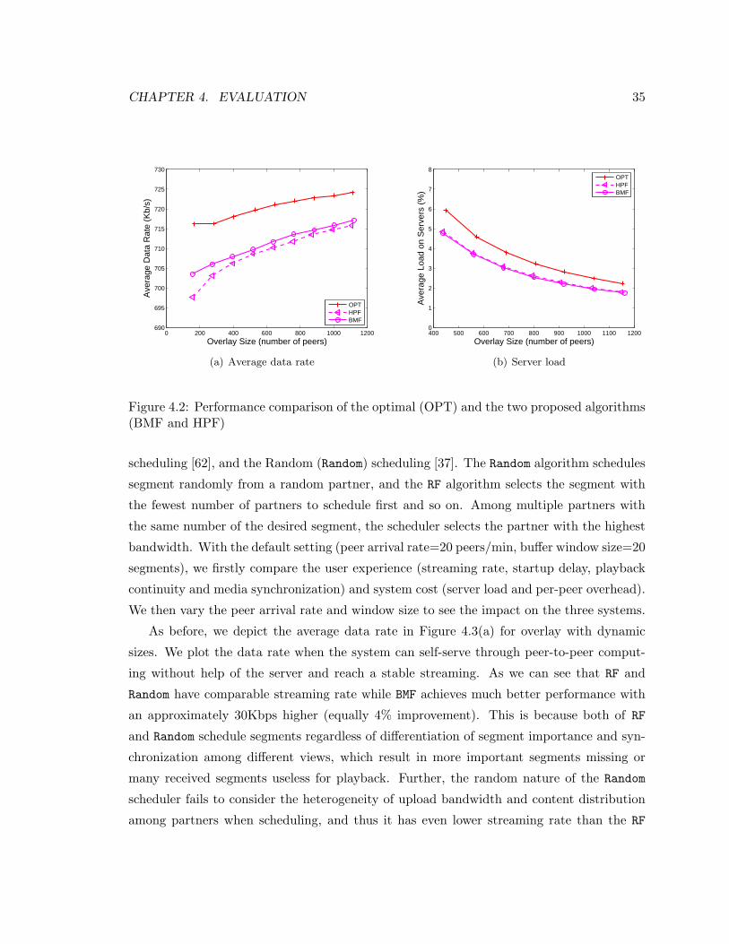
CHAPTER 4. EVALUATION 35
0 200 400 600 800 1000 1200690
695
700
705
710
715
720
725
730
Overlay Size (number of peers)
Ave
rage
Dat
a R
ate
(Kb/
s)
OPTHPFBMF
(a) Average data rate
400 500 600 700 800 900 1000 1100 12000
1
2
3
4
5
6
7
8
Overlay Size (number of peers)
Ave
rage
Loa
d on
Ser
vers
(%
)
OPTHPFBMF
(b) Server load
Figure 4.2: Performance comparison of the optimal (OPT) and the two proposed algorithms(BMF and HPF)
scheduling [62], and the Random (Random) scheduling [37]. The Random algorithm schedules
segment randomly from a random partner, and the RF algorithm selects the segment with
the fewest number of partners to schedule first and so on. Among multiple partners with
the same number of the desired segment, the scheduler selects the partner with the highest
bandwidth. With the default setting (peer arrival rate=20 peers/min, buffer window size=20
segments), we firstly compare the user experience (streaming rate, startup delay, playback
continuity and media synchronization) and system cost (server load and per-peer overhead).
We then vary the peer arrival rate and window size to see the impact on the three systems.
As before, we depict the average data rate in Figure 4.3(a) for overlay with dynamic
sizes. We plot the data rate when the system can self-serve through peer-to-peer comput-
ing without help of the server and reach a stable streaming. As we can see that RF and
Random have comparable streaming rate while BMF achieves much better performance with
an approximately 30Kbps higher (equally 4% improvement). This is because both of RF
and Random schedule segments regardless of differentiation of segment importance and syn-
chronization among different views, which result in more important segments missing or
many received segments useless for playback. Further, the random nature of the Random
scheduler fails to consider the heterogeneity of upload bandwidth and content distribution
among partners when scheduling, and thus it has even lower streaming rate than the RF
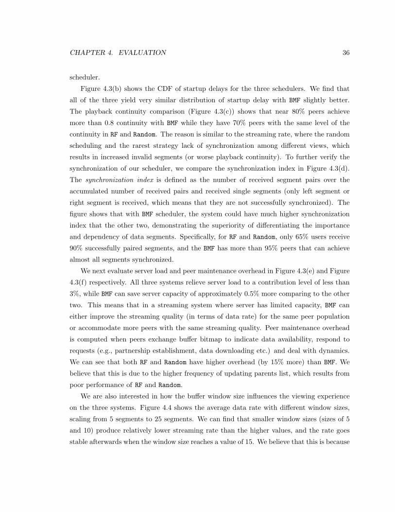
CHAPTER 4. EVALUATION 36
scheduler.
Figure 4.3(b) shows the CDF of startup delays for the three schedulers. We find that
all of the three yield very similar distribution of startup delay with BMF slightly better.
The playback continuity comparison (Figure 4.3(c)) shows that near 80% peers achieve
more than 0.8 continuity with BMF while they have 70% peers with the same level of the
continuity in RF and Random. The reason is similar to the streaming rate, where the random
scheduling and the rarest strategy lack of synchronization among different views, which
results in increased invalid segments (or worse playback continuity). To further verify the
synchronization of our scheduler, we compare the synchronization index in Figure 4.3(d).
The synchronization index is defined as the number of received segment pairs over the
accumulated number of received pairs and received single segments (only left segment or
right segment is received, which means that they are not successfully synchronized). The
figure shows that with BMF scheduler, the system could have much higher synchronization
index that the other two, demonstrating the superiority of differentiating the importance
and dependency of data segments. Specifically, for RF and Random, only 65% users receive
90% successfully paired segments, and the BMF has more than 95% peers that can achieve
almost all segments synchronized.
We next evaluate server load and peer maintenance overhead in Figure 4.3(e) and Figure
4.3(f) respectively. All three systems relieve server load to a contribution level of less than
3%, while BMF can save server capacity of approximately 0.5% more comparing to the other
two. This means that in a streaming system where server has limited capacity, BMF can
either improve the streaming quality (in terms of data rate) for the same peer population
or accommodate more peers with the same streaming quality. Peer maintenance overhead
is computed when peers exchange buffer bitmap to indicate data availability, respond to
requests (e.g., partnership establishment, data downloading etc.) and deal with dynamics.
We can see that both RF and Random have higher overhead (by 15% more) than BMF. We
believe that this is due to the higher frequency of updating parents list, which results from
poor performance of RF and Random.
We are also interested in how the buffer window size influences the viewing experience
on the three systems. Figure 4.4 shows the average data rate with different window sizes,
scaling from 5 segments to 25 segments. We can find that smaller window sizes (sizes of 5
and 10) produce relatively lower streaming rate than the higher values, and the rate goes
stable afterwards when the window size reaches a value of 15. We believe that this is because
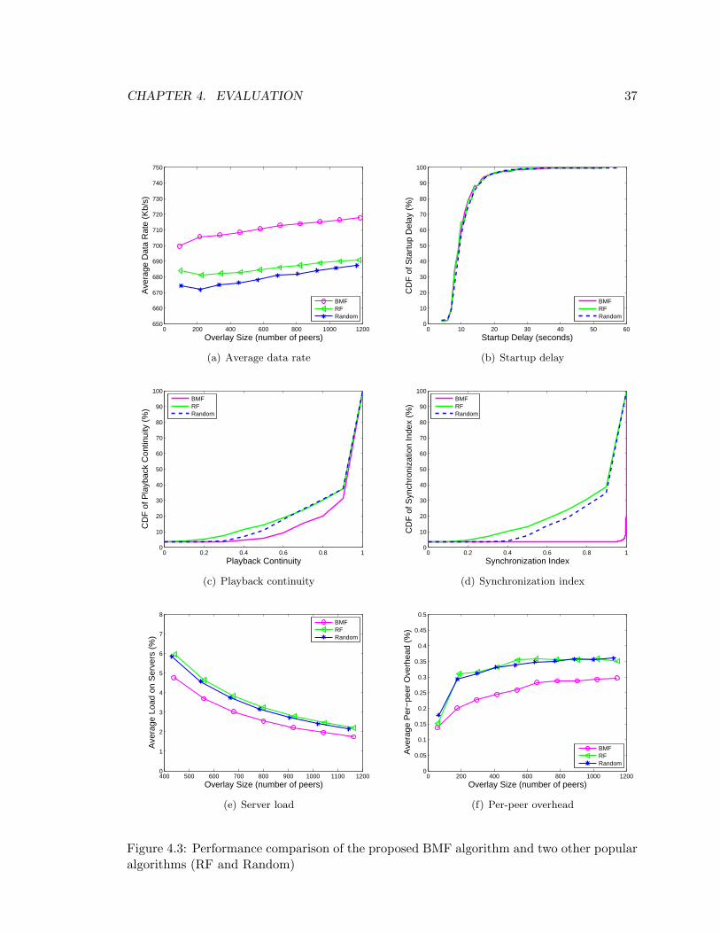
CHAPTER 4. EVALUATION 37
0 200 400 600 800 1000 1200650
660
670
680
690
700
710
720
730
740
750
Overlay Size (number of peers)
Ave
rage
Dat
a R
ate
(Kb/
s)
BMFRFRandom
(a) Average data rate
0 10 20 30 40 50 600
10
20
30
40
50
60
70
80
90
100
Startup Delay (seconds)
CD
F o
f Sta
rtup
Del
ay (
%)
BMFRFRandom
(b) Startup delay
0 0.2 0.4 0.6 0.8 10
10
20
30
40
50
60
70
80
90
100
Playback Continuity
CD
F o
f Pla
ybac
k C
ontin
uity
(%
)
BMFRFRandom
(c) Playback continuity
0 0.2 0.4 0.6 0.8 10
10
20
30
40
50
60
70
80
90
100
Synchronization Index
CD
F o
f Syn
chro
niza
tion
Inde
x (%
)
BMFRFRandom
(d) Synchronization index
400 500 600 700 800 900 1000 1100 12000
1
2
3
4
5
6
7
8
Overlay Size (number of peers)
Ave
rage
Loa
d on
Ser
vers
(%
)
BMFRFRandom
(e) Server load
0 200 400 600 800 1000 12000
0.05
0.1
0.15
0.2
0.25
0.3
0.35
0.4
0.45
0.5
Overlay Size (number of peers)
Ave
rage
Per
−pe
er O
verh
ead
(%)
BMFRFRandom
(f) Per-peer overhead
Figure 4.3: Performance comparison of the proposed BMF algorithm and two other popularalgorithms (RF and Random)
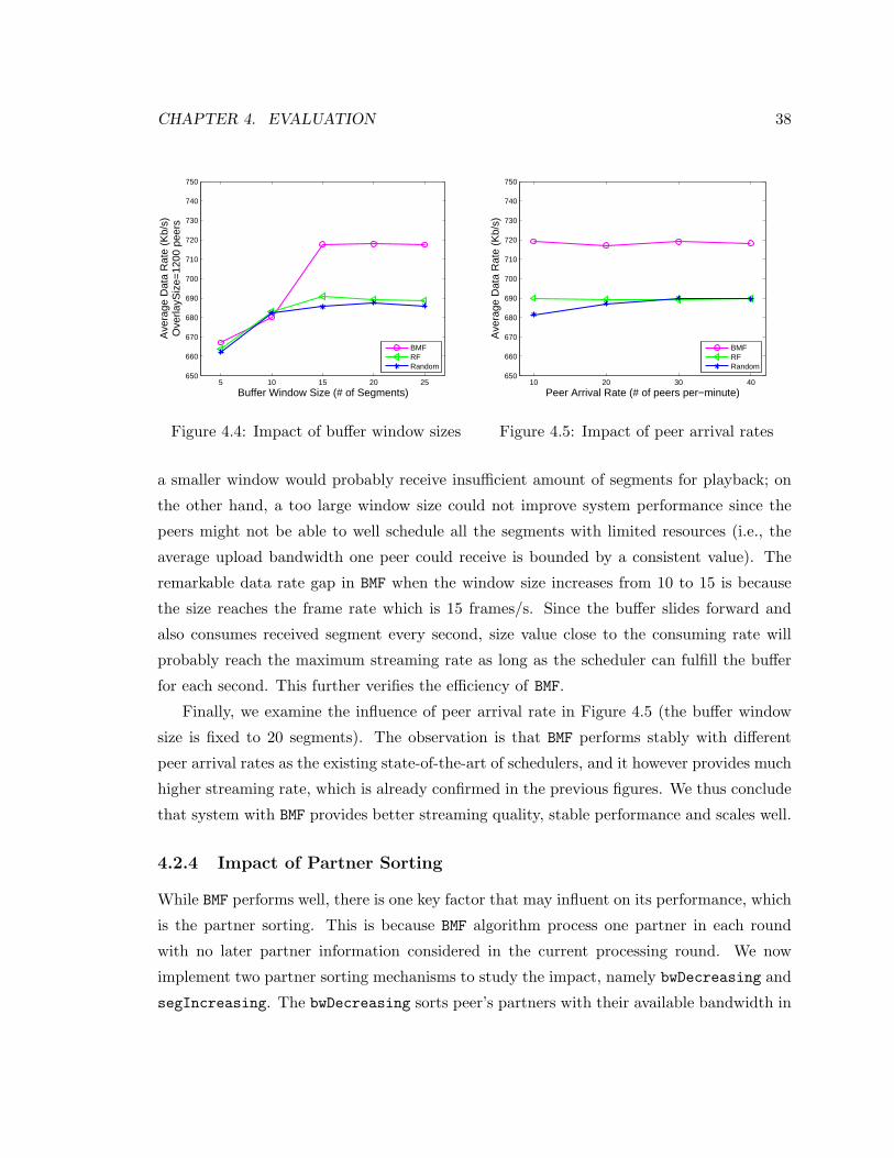
CHAPTER 4. EVALUATION 38
5 10 15 20 25650
660
670
680
690
700
710
720
730
740
750
Buffer Window Size (# of Segments)
Ave
rage
Dat
a R
ate
(Kb/
s)O
verla
ySiz
e=12
00 p
eers
BMFRFRandom
Figure 4.4: Impact of buffer window sizes
10 20 30 40650
660
670
680
690
700
710
720
730
740
750
Peer Arrival Rate (# of peers per−minute)
Ave
rage
Dat
a R
ate
(Kb/
s)
BMFRFRandom
Figure 4.5: Impact of peer arrival rates
a smaller window would probably receive insufficient amount of segments for playback; on
the other hand, a too large window size could not improve system performance since the
peers might not be able to well schedule all the segments with limited resources (i.e., the
average upload bandwidth one peer could receive is bounded by a consistent value). The
remarkable data rate gap in BMF when the window size increases from 10 to 15 is because
the size reaches the frame rate which is 15 frames/s. Since the buffer slides forward and
also consumes received segment every second, size value close to the consuming rate will
probably reach the maximum streaming rate as long as the scheduler can fulfill the buffer
for each second. This further verifies the efficiency of BMF.
Finally, we examine the influence of peer arrival rate in Figure 4.5 (the buffer window
size is fixed to 20 segments). The observation is that BMF performs stably with different
peer arrival rates as the existing state-of-the-art of schedulers, and it however provides much
higher streaming rate, which is already confirmed in the previous figures. We thus conclude
that system with BMF provides better streaming quality, stable performance and scales well.
4.2.4 Impact of Partner Sorting
While BMF performs well, there is one key factor that may influent on its performance, which
is the partner sorting. This is because BMF algorithm process one partner in each round
with no later partner information considered in the current processing round. We now
implement two partner sorting mechanisms to study the impact, namely bwDecreasing and
segIncreasing. The bwDecreasing sorts peer’s partners with their available bandwidth in
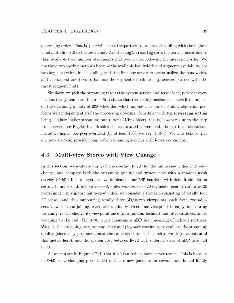
CHAPTER 4. EVALUATION 39
decreasing order. That is, peer will select the partner to process scheduling with the highest
bandwidth first till to the lowest one. And the segIncreasing sorts the partner according to
their available total number of segments that peer wants, following the increasing order. We
use these two sorting methods because the available bandwidth and segments availability are
two key constraints in scheduling, with the first one serves to better utilize the bandwidth,
and the second one tries to balance the segment distribution (processes partner with the
rarest segment first).
Similarly, we pick the streaming rate as the system service and server load, per-peer over-
head as the system cost. Figure 4.6(a) shows that the sorting mechanisms have little impact
on the streaming quality of BMF scheduler, which implies that our scheduling algorithm per-
forms well independently of the processing ordering. Scheduler with bwDecreasing sorting
brings slightly higher streaming rate (about 2Kbps higer), this is, however, due to the help
from server; see Fig.4.6(b). Besides the aggravated server load, the sorting mechanisms
introduce higher per-peer overhead (by at least 15%, see Fig. 4.6(c)). We thus believe that
our pure BMF can provide comparable streaming services with lower system cost.
4.3 Multi-view Stereo with View Change
In this section, we evaluate our V-Plane overlay (H-VO) for the multi-view video with view
change, and compare both the streaming quality and system cost with a random mesh
overlay (H-RO). In both systems, we implement our BMF heuristic with default simulation
setting (number of direct partners=8, buffer window size=20 segments, peer arrival rate=20
peers/min). To support multi-view video, we consider a scenario consisting of totally four
2D views (and thus supporting totally three 3D/stereo viewpoints, each from two adja-
cent views). Upon joining, each peer randomly selects one viewpoint to enjoy, and during
watching, it will change its viewpoint once (in a random fashion) and afterwards continues
watching to the end. For H-VO, peers maintain a uDP list consisting of indirect partners.
We pick the streaming rate, startup delay and playback continuity to evaluate the streaming
quality (since they produce almost the same synchronization index, we skip evaluation of
this metric here), and the system cost between H-VO with different sizes of uDP lists and
H-RO.
As we can see in Figure 4.7(d) that H-VO can reduce more server traffic. This is because
in H-RO, view changing peers failed to locate new partners for several rounds and finally
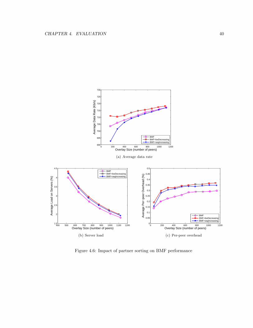
CHAPTER 4. EVALUATION 40
0 200 400 600 800 1000 1200690
695
700
705
710
715
720
725
730
Overlay Size (number of peers)
Ave
rage
Dat
a R
ate
(Kb/
s)
BMFBMF+bwDecreasingBMF+segIncreasing
(a) Average data rate
400 500 600 700 800 900 1000 1100 12001.5
2
2.5
3
3.5
4
4.5
Overlay Size (number of peers)
Ave
rage
Loa
d on
Ser
vers
(%
)
BMFBMF+bwDecreasingBMF+segIncreasing
(b) Server load
0 200 400 600 800 1000 12000
0.05
0.1
0.15
0.2
0.25
0.3
0.35
0.4
0.45
0.5
Overlay Size (number of peers)
Ave
rage
Per
−pe
er O
verh
ead
(%)
BMFBMF+bwDecreasingBMF+segIncreasing
(c) Per-peer overhead
Figure 4.6: Impact of partner sorting on BMF performance
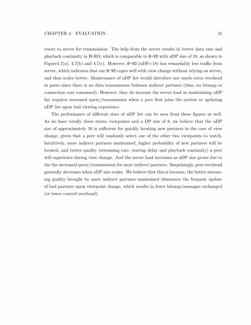
CHAPTER 4. EVALUATION 41
resort to server for transmission. The help from the server results in better data rate and
playback continuity in H-RO, which is comparable to H-VO with uDP size of 18, as shown in
Figure4.7(a), 4.7(b) and 4.7(c). However, H-VO (uDP=18) has remarkably less traffic from
server, which indicates that our H-VO copes well with view change without relying on server,
and thus scales better. Maintenance of uDP list would introduce not much extra overhead
in peers since there is no data transmission between indirect partners (thus, no bitmap or
connection cost consumed). However, they do increase the server load as maintaining uDP
list requires increased query/transmission when a peer first joins the system or updating
uDP list upon bad viewing experience.
The performance of different sizes of uDP list can be seen from these figures as well.
As we have totally three stereo viewpoints and a DP size of 8, we believe that the uDP
size of approximately 16 is sufficient for quickly locating new partners in the case of view
change, given that a peer will randomly select one of the other two viewpoints to watch.
Intuitively, more indirect partners maintained, higher probability of new partners will be
located, and better quality (streaming rate, startup delay and playback continuity) a peer
will experience during view change. And the server load increases as uDP size grows due to
the the increased query/transmission for more indirect partners. Surprisingly, peer overhead
generally decreases when uDP size scales. We believe that this is because, the better stream-
ing quality brought by more indirect partners maintained eliminates the frequent update
of bad partners upon viewpoint change, which results in fewer bitmap/messages exchanged
(or lower control overhead).
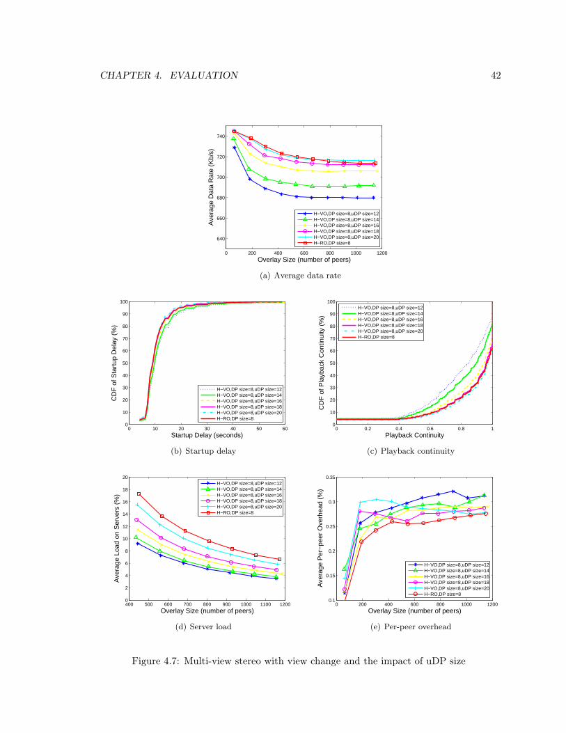
CHAPTER 4. EVALUATION 42
0 200 400 600 800 1000 1200
640
660
680
700
720
740
Overlay Size (number of peers)
Ave
rage
Dat
a R
ate
(Kb/
s)
H−VO,DP size=8,uDP size=12H−VO,DP size=8,uDP size=14H−VO,DP size=8,uDP size=16H−VO,DP size=8,uDP size=18H−VO,DP size=8,uDP size=20H−RO,DP size=8
(a) Average data rate
0 10 20 30 40 50 600
10
20
30
40
50
60
70
80
90
100
Startup Delay (seconds)
CD
F o
f Sta
rtup
Del
ay (
%)
H−VO,DP size=8,uDP size=12H−VO,DP size=8,uDP size=14H−VO,DP size=8,uDP size=16H−VO,DP size=8,uDP size=18H−VO,DP size=8,uDP size=20H−RO,DP size=8
(b) Startup delay
0 0.2 0.4 0.6 0.8 10
10
20
30
40
50
60
70
80
90
100
Playback Continuity
CD
F o
f Pla
ybac
k C
ontin
uity
(%
)
H−VO,DP size=8,uDP size=12H−VO,DP size=8,uDP size=14H−VO,DP size=8,uDP size=16H−VO,DP size=8,uDP size=18H−VO,DP size=8,uDP size=20H−RO,DP size=8
(c) Playback continuity
400 500 600 700 800 900 1000 1100 12000
2
4
6
8
10
12
14
16
18
20
Overlay Size (number of peers)
Ave
rage
Loa
d on
Ser
vers
(%
)
H−VO,DP size=8,uDP size=12H−VO,DP size=8,uDP size=14H−VO,DP size=8,uDP size=16H−VO,DP size=8,uDP size=18H−VO,DP size=8,uDP size=20H−RO,DP size=8
(d) Server load
0 200 400 600 800 1000 12000.1
0.15
0.2
0.25
0.3
0.35
Overlay Size (number of peers)
Ave
rage
Per
−pe
er O
verh
ead
(%)
H−VO,DP size=8,uDP size=12H−VO,DP size=8,uDP size=14H−VO,DP size=8,uDP size=16H−VO,DP size=8,uDP size=18H−VO,DP size=8,uDP size=20H−RO,DP size=8
(e) Per-peer overhead
Figure 4.7: Multi-view stereo with view change and the impact of uDP size
Chapter 5
Conclusion and Future Work
This thesis offered a preliminary study on efficient streaming of 3D/multi-view videos over
peer-to-peer networks. We focus on the segment scheduler design, which is the key compo-
nent in peer-to-peer streaming systems. We demonstrated that the inherent multi-stream
nature of stereo video makes segment scheduling more difficult, particularly with the exis-
tence of multiple senders in a peer-to-peer overlay. We mathematically formulate the stereo
segment scheduling as a BQP problem to maximize the number of weighted segment pairs,
which is NP-Hard. Given the stringent playback requirement in real time video stream-
ing, the optimal solution is too computationally costly to obtained. We thus develop two
heuristics to efficiently update the scheduling. With theoretical analysis and simulation,
we show that the proposed algorithms achieve near-optimal performance and outperforms
other popular algorithms. We further extend the design to support multi-view video.
There are a number of possible future avenues to explore. We are currently work-
ing on more advanced weight modeling of the segment pair based on the rate-distortion
model. Besides, we continue on developing the overlay design to fully support multi-view
with more views and higher view diversity/dynamics. We are also interested in building
and experimenting prototypes with the H.264 MVC codec on on-demand streaming with
3D/multi-view video.
43
Bibliography
[1] BitTorrent. http://www.bittorrent.com/.
[2] Gnutella. http://www.gnutella.com/.
[3] ILOG CPLEX. http://www.ilog.com/products/cplex/.
[4] Joint Multiview Coding (JMVC) 8.0. garcon.ient.rwthaachen.de.
[5] MERL. http://www.merl.com/.
[6] PPLive. http://www.pplive.com/.
[7] UUSee. http://www.uusee.com/.
[8] A. Aksay, S. Pehlivan, E. Kurutepe, C. Bilen, T. Ozcelebi, G.B. Akar, M.R. Civanlar,and A.M. Tekalp. End-to-end Stereoscopic Video Streaming with Content-adaptiveRate and Format Control. Signal Processing: Image Communication, 22(2):157–168,2007.
[9] S. Banerjee, B. Bhattacharjee, and C. Kommareddy. Scalable Application Layer Mul-ticast. In Proc. of ACM SIGCOMM’02.
[10] F. Boronat, J. Lloret, and M. Garcıa. Multimedia Group and Inter-stream Synchro-nization Techniques: A Comparative Study. Information Systems, 34(1):108–131, 2009.
[11] Bin Chang, Liang Dai, Yi Cui, and Yuan Xue. On Feasibility of P2P On-DemandStreaming via Empirical VoD User Behavior Analysis. In Proc. of ICDCS’08 Workshop.
[12] Bin Cheng, Lex Stein, Hai Jin, Xiaofei Liao, and Zheng Zhang. GridCast: ImprovingPeer Sharing for P2P VoD. ACM Transactions on Multimedia Computing, Communi-cations and Applications, 4(4):1–31, October 2008.
[13] X. Cheng, F. Wang, J. Liu, and K. Xu. Collaborative Delay-aware Scheduling in Peer-to-Peer UGC Video Sharing. In Proc.of NOSSDAV’10.
[14] P.A. Chou, H.J. Wang, and V.N. Padmanabhan. Layered Multiple Description Coding.In Proc. of PV’03.
44
BIBLIOGRAPHY 45
[15] Y. Ding, J. Liu, D. Wang, and H. Jiang. Peer-to-Peer Video-on-Demand with ScalableVideo Coding. Computer Communications, 33(14):1589–1597, 2010.
[16] Y. Guo, C. Liang, and Y. Liu. AQCS: Adaptive Queue-based Chunk Scheduling forP2P Live Streaming. In Proc. of IFIP’08.
[17] T. Hashimoto and Y. Ishibashi. Group Synchronization Control over Haptic Media ina Networked Real-time Game with Collaborative Work. In Proc.of ACM SIGCOMMNetGames ’06.
[18] Y. He, G. Siganos, M. Faloutsos, and S. Krishnamurthy. A Systematic Framework forUnearthing the Missing Links: Measurements and Impact. In Proc. of NSDI’07.
[19] C.H. Hsu and M. Hefeeda. Quality-aware Segment Transmission Scheduling in Peer-to-Peer Streaming Systems. In Proc. of ACM MMSys’10.
[20] Shun-Yun Hu, J.-R. Jiang, and Bing-Yu Chen. Peer-to-Peer 3D Streaming. IEEEInternet Computing, 14(2):54–61, 2010.
[21] S.Y. Hu, T.H. Huang, S.C. Chang, W.L. Sung, J.R. Jiang, and B.Y. Chen. FloD: AFramework for Peer-to-Peer 3D Streaming. In Proc.of IEEE INFOCOM’08.
[22] C. Huang, J. Li, and K.W. Ross. Can Internet Video-on-Demand be Profitable? InProc. of ACM SIGCOMM’07.
[23] Z. Huang, W. Wu, K. Nahrstedt, A. Arefin, and R. Rivas. TSync: A New Synchro-nization Framework for Multi-site 3D Tele-immersion. In Proc.of NOSSDAV’06.
[24] Y. Ishibashi and S. Tasaka. A Synchronization Mechanism for Continuous Media inMultimedia Communications. In Proc.of IEEE INFOCOM’95.
[25] T.V. Johnson and A. Zhang. Dynamic Playout Scheduling Algorithms for ContinuousMultimedia Streams. Multimedia Systems, 7(4):312–325, 1999.
[26] K. Katayama and H. Narihisa. Performance of Simulated Annealing-based Heuristicfor The Unconstrained Binary Quadratic Programming Problem. European Journal ofOperational Research, 134(1):103–119, 2001.
[27] P. Kauff, N. Atzpadin, C. Fehn, M. Muller, O. Schreer, A. Smolic, and R. Tanger. DepthMap Creation and Image-based Rendering for Advanced 3DTV Services ProvidingInteroperability and Scalability. Signal Processing: Image Communication, 22(2):217–234, 2007.
[28] E. Kurutepe, A. Aksay, C. Bilen, C.G. Gurler, T. Sikora, G.B. Akar, and A.M. Tekalp.A Standards-based, Flexible, End-to-End Multi-view Video Streaming Architecture. InProc. of PV’07.
BIBLIOGRAPHY 46
[29] E. Kurutepe, M.R. Civanlar, and A.M. Tekalp. Interactive Transport of Multi-viewVideos for 3DTV Applications. Journal of Zhejiang University Science, 7(5):830–836,2006.
[30] E. Kurutepe, M.R. Civanlar, and A.M. Tekalp. Client-Driven Selective Streaming ofMultiview Video for Interactive 3DTV. IEEE Transactions on Circuits and Systemsfor Video Technology, 17(11):1558–1565, October 2007.
[31] E. Kurutepe and T. Sikora. Feasibility of Multi-view Video Streaming over P2P Net-works. In Proc. of 3DTVCON’08.
[32] E. Lamboray, W. Stephan, et al. Real-Time Streaming of Point-based 3D Video. InProc. of IEEE VR’04.
[33] D.T. Lee. On k-Nearest Neighbor Voronoi Diagrams in The Plane. IEEE Transactionson Computers, 100(6):478–487, 1982.
[34] B. Li, G.Y. Keung, S. Xie, F. Liu, Y. Sun, and H. Yin. An Empirical Study of FlashCrowd Dynamics in a P2P-based Live Video Streaming System. In Proc. of IEEEGLOBECOM’08.
[35] L. Li, A. Karmouch, and ND Georganas. Real-time Synchronization Control in Mul-timedia Distributed Systems. ACM SIGCOMM Computer Communication Review,22(3):79–87, 1992.
[36] Taoyu Li, Minghua Chen, Dah-Ming Chiu, and Maoke Chen. Queuing Models forPeer-to-peer Systems. In Proc. of IPTPS’09.
[37] C. Liang, Y. Guo, and Y. Liu. Is Random Scheduling Sufficient in P2P Video Stream-ing? In Proc. of ICDCS’08.
[38] J. Liu, S.G. Rao, B. Li, and H. Zhang. Opportunities and Challenges of Peer-to-Peerinternet Video Broadcast. Proceedings of the IEEE, 96(1):11–24, January 2008.
[39] K. Lua, J. Crowcroft, M. Pias, R. Sharma, and S. Lim. A Survey and Comparison ofPeer-to-Peer Overlay Network Schemes. IEEE Communications Survey and Tutorial,7(2):72–93, 2004.
[40] N. Magharei and R. Rejaie. Prime: Peer-to-Peer Receiver-drIven MEsh-based Stream-ing. IEEE/ACM Transactions on Networking, 17(4):1052–1065, 2009.
[41] W. Matusik and H. Pfister. 3D TV: a Scalable System for Real-Time Acquisition,Transmission, and Autostereoscopic Display of Dynamic Scenes. In Proc. of ACMSIGGRAPH’04.
[42] JVT of MPEG and ITU-T. Joint Draft 7.0 on Multiview Video Coding (JVT-AA209).Augest 2008.
BIBLIOGRAPHY 47
[43] D.E. Ott and K. Mayer-Patel. Coordinated Multi-streaming for 3D Tele-immersion. InProc. of ACM MM’04.
[44] G. Petrovic et al. Near-Future Streaming Framework for 3D-TV Applications. In Proc.of ICME’06.
[45] S. Ramanathan and P.V. Rangan. Feedback Techniques for Intra-media Continuityand Inter-media Synchronization in Distributed Multimedia Systems. The ComputerJournal, 36(1):19–31, 1993.
[46] S. Ratsanamy, P. Francis, M. Handley, R. Karp, and S. Shenker. A Scalable ContentAddressable Network. In Proc. of ACM SIGCOMM’01.
[47] M. Saxena, U. Sharan, and S. Fahmy. Analyzing Video Services in Web 2.0: A GlobalPerspective. In Proc. of NOSSDAV’08.
[48] L. Smith. Space Perception and Parallax. Philosophy, 56(216):248–252, 1981.
[49] R. Steinmetz. Synchronization Properties in Multimedia Systems. IEEE Journal onSelected Areas in Communications, 8(3):401–412, 1990.
[50] I. Stoica, R. Morris, D. Karger, M.F. Kaashoek, and H. Balakrishnan. Chord: A Scal-able Peer-to-Peer Lookup Service for Internet Applications. ACM SIGCOMM Com-puter Communication Review, 31(4):149–160, 2001.
[51] W.L. Sung, S.Y. Hu, and J.R. Jiang. Selection Strategies for Peer-to-Peer 3D Streaming.In Proc.of NOSSDAV’08.
[52] D. Tian and G. AlRegib. Multistreaming of 3D Scenes with Optimized Transmissionand Rendering Scalability. IEEE Transactions on Multimedia, 9(4):736–745, 2007.
[53] D.A. Tran, K.A. Hua, and T. Do. Zigzag: An Efficient Peer-to-Peer Scheme for MediaStreaming. In Proc. of IEEE INFOCOM’03.
[54] V. Venkataraman, K. Yoshida, and P. Francis. Chunkyspread: Heterogeneous Unstruc-tured Tree-Based Peer-to-Peer Multicast. In Proc. of IEEE ICNP’06.
[55] F. Wang, Y. Xiong, and J. Liu. mTreebone: A Hybrid Tree/Mesh Overlay forApplication-Layer Live Video Multicast. In Proc. of ICDCS’07.
[56] J. Wang, C. Yeo, V. Prabhakaran, and K. Ramchandran. On the Role of Helpers inPeer-to-Peer File Download Systems: Design, Analysis and Simulation. In Proc. ofIPTPS’07.
[57] Y. Wang, Z. Wu, and J.M. Boyce. Modeling of Transmission-Loss-Induced Distortionin Decoded Video. IEEE Transactions on Circuits and Systems for Video Technology,16(6):716–732, 2006.
BIBLIOGRAPHY 48
[58] Y.-K. Wang and T. Schierl. RTP Payload Format for MVC Video. In draft-wang-avt-rtp-mvc-05.
[59] W. Wu, Z. Yang, I. Gupta, and K. Nahrstedt. Towards Multi-site Collaboration in 3DTele-immersive Environments. In Proc. of ICDCS’08.
[60] X. Xin, SHI Yuanchun, GAO Yuan, and Q. Zhang. LayerP2P: A New Data Schedul-ing Approach for Layered Streaming in Heterogeneous Networks. In Proc. of IEEEINFOCOM’09.
[61] Z. Yang, B. Yu, K. Nahrstedt, and R. Bajscy. A Multi-stream Adaptation Frameworkfor Bandwidth Management in 3D Tele-immersion. In Proc.of NOSSDAV’06.
[62] X. Zhang, J. Liu, B. Li, and T.S.P. Yum. CoolStreaming/DONet: A Data-drivenOverlay Network for Efficient Live Media Streaming. In Proc. of IEEE INFOCOM’05.