Embed Size (px)
Citation preview
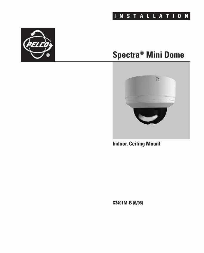
I N S T A L L A T I O N
Spectra
®
Mini Dome
C3401M-B (6/06)
Indoor, Ceiling Mount

Important Safety Instructions1. Read these instructions.
2. Keep these instructions.
3. Heed all warnings.
4. Follow all instructions.
5. Do not block any ventilation openings. Install in accordance with the manufacturer’s instructions.
6. Do not install near any heat sources such as radiators, heat registers, stoves, or other apparatus (including amplifiers) that produce heat.
7. Only use attachments/accessories specified by the manufacturer.
8. Use only with the cart, stand, tripod, bracket, or table specified by the manufacturer, or sold with the apparatus. When a cart is used, use caution when moving the cart/apparatus combination to avoid injury from tip-over.
9. Refer all servicing to qualified service personnel. Servicing is required when the apparatus has been damaged in any way, such as power-supply cord or plug is damaged, liquid has been spilled or objects have fallen into the apparatus, the apparatus has been exposed to rain or moisture, does not operate normally, or has been dropped.
10. Installation should be done only by qualified personnel and conform to all local codes.
11. Unless the unit is specifically marked as a NEMA Type 3, 3R, 3S, 4, 4X, 6, or 6P enclosure, it is designed for indoor use only and it must not be installed where exposed to rain and moisture.
12. Use only installation methods and materials capable of supporting four times the maximum specified load.
13. Use stainless steel hardware to fasten the mount to outdoor surfaces.
14. To prevent damage from water leakage when installing a mount outdoors on a roof or wall, apply sealant around the bolt holes between the mount and mounting surface.
15. CAUTION: These servicing instructions are for use by qualified service personnel only. To reduce the risk of electric shock do not perform any servicing other that contained in the operating instructions unless you are qualified to do so.
16. Only use replacement parts recommended by Pelco.
The product and/or manual may bear the following marks:
This symbol indicates that dangerous voltage constituting a risk of electric shock is present within this unit
This symbol indicates that there are important operating and maintenance instructions in the literature accompanying this unit.
CAUTION:
RISK OF ELECTRIC SHOCK. DO NOT OPEN.
C3401M-B (6/06) 3

Regulatory NoticesThis device complies with Part 15 of the FCC Rules. Operation is subject to the following two conditions: (1) this device may not cause harmful interference, and (2) this device must accept any interference received, including interference that may cause undesired operation.
RADIO AND TELEVISION INTERFERENCE
This equipment has been tested and found to comply with the limits of a Class B digital device, pursuant to Part 15 of the FCC Rules. These limits are designed to provide reasonable protection against harmful interference in a residential instal-lation. This equipment generates, uses, and can radiate radio frequency energy and, if not installed and used in accor-dance with the instructions, may cause harmful interference to radio communications. However there is no guarantee that the interference will not occur in a particular installation. If this equipment does cause harmful interference to radio or television reception, which can be determined by turning the equipment off and on, the user is encouraged to try to correct the interference by one or more of the following measures:
• Reorient or relocate the receiving antenna.
• Increase the separation between the equipment and the receiver.
• Connect the equipment into an outlet on a circuit different from that to which the receiver is connected.
• Consult the dealer or an experienced radio/TV technician for help.
You may also find helpful the following booklet, prepared by the FCC: “How to Identify and Resolve Radio-TV Interference Problems.” This booklet is available from the U.S. Government Printing Office, Washington D.C. 20402.
Changes and Modifications not expressly approved by the manufacturer or registrant of this equipment can void your authority to operate this equipment under Federal Communications Commission’s rules.
This Class B digital apparatus complies with Canadian ICES-003.
4 C3401M-B (6/06)

DescriptionThe Spectra® Mini is an indoor dome system designed for ceiling applications. The dome can be mounted to the surface of ceilings, or it can be recessed in hard ceilings or standard 2 x 2 ft (61 x 61 cm) tiles in suspended ceilings. The Spectra Mini includes a high resolution color camera; video output capability through either coaxial cable or UTP wiring; pan/tilt control using D, P, or Coaxitron® protocol; and on-screen programming.
A translator board can be installed on the dome for communication with non-Pelco controllers. The dome is compatible with the following translator boards:
TXB-AD Translator board for American Dynamics controllers
TXB-B Translator board for Philips (Burle) controllers
TXB-S422 Translator board for Sensormatic controllers
TXB-V Translator board for Vicon controllers
MODELSSD4-B0 Indoor dome system, black, smoked bubble, NTSC
SD4-B1 Indoor dome system, black, clear bubble, NTSC
SD4-B0-X Indoor dome system, black, smoked bubble, PAL
SD4-B1-X Indoor dome system, black, clear bubble, PAL
SD4-W0 Indoor dome system, white, smoked bubble, NTSC
SD4-W1 Indoor dome system, white, clear bubble, NTSC
SD4-W0-X Indoor dome system, white, smoked bubble, PAL
SD4-W1-X Indoor dome system, white, clear bubble, PAL
C3401M-B (6/06) 5

InstallationThe following parts are supplied with the Spectra Mini dome system:
1 Dome drive
1 Dome bubble with trim ring
1 Interface cable with a male RJ45-10 connector on one end and four twisted wire pairs on the other end
1 Cover for use with optional translator board
2 #10 x 1.50-inch self-tapping screws for suspended ceiling installation
2 #8 x 3.50-inch self-tapping screws for surface mount installation
1 Installation manual
1 Operation/Programming manual
1 Template
The following parts, in addition to normal installation tools, are needed but not supplied:
1 Small flashlight for viewing switches
1 Long-handled flat-blade screwdriver for setting switches
2 6-32 toggle bolts for surface mount installation
2 8-32 studs and nuts for surface mount installation to concrete
2 3-16 toggle bolts for recessed installation in hard ceiling
Figure 1. Package Components
MANUALSINTERFACE CABLEAND RJ45-10CONNECTOR
DOME DRIVE TRIM RING ANDBUBBLE
1.5-INCH SELF-TAPPINGSCREWS, 2 EA.
3.5-INCH SELF-TAPPINGSCREWS, 2 EA.
TRANSLATOR BOARDCOVER
6 C3401M-B (6/06)

SWITCH SETTINGSCoaxitron control: If you are going to use Coaxitron protocol to communicate with the dome system, you do not have to set any switches. Proceed to the installation instructions that follow this section.
Non-Pelco control: If you are going to install a protocol translator board to communicate with the dome system through a non-Pelco controller, proceed to the installation instructions that follow this section. When you are instructed to install the translator board, you will set the switches as described in the installation/operation manual that accompanies the translator board.
D or P control: If you are going to use D or P protocol to communicate with the dome system, follow the steps below to set the switches. Refer to Figure 2.
1. Place the dome drive on a flat surface with the dome liner pointing up.
2. Point the camera straight up.
3. Using a flashlight, look straight down through the viewing slot of the dome liner. Look at the circuit board in the bottom of the housing. Rotate the dome liner until you see two DIP switches on the circuit board.
4. Set the switches. Refer to Table A, Table B, and Table C. There are no settings for SW1.
NOTE: The unit automatically detects D or P protocol.
Figure 2. Component Locations
DATA PORTThe data port (refer to Figure 2) allows access for on-site setup and testing of the dome system. It also is used for uploading revised operating software and language files. Refer to Software/Language File Upload in the Operation/Programming manual.
WARNING: Do not remove the dome liner (refer to Figure 2). Replacing the dome liner requires qualified service personnel; otherwise, the dome drive may not operate properly.
SW 3
SW 2
ON
ON
REMOTEDATAPORT
DOMELINER
C3401M-B (6/06) 7

*If you are connecting a single dome to a controller, terminate the dome. When connecting more than one dome to a single controller, terminate the dome farthest from the controller.
Table A. Switch Settings for SW2
Special Systems
Switch Number SW2-1 SW2-2 SW2-3 SW2-4 SW2-5 SW2-6 SW2-7 SW2-8 SW2-9
AD-32 Preset System ON
CM9502 Setting ON
Baud Rate
Switch Number SW2-1 SW2-2 SW2-3 SW2-4 SW2-5 SW2-6 SW2-7 SW2-8 SW2-9
2400 Baud OFF OFF OFF
4800 Baud ON OFF OFF
9600 Baud OFF ON OFF
Protocol Termination
Switch Number SW2-1 SW2-2 SW2-3 SW2-4 SW2-5 SW2-6 SW2-7 SW2-8 SW2-9
Terminated ON*
Not Terminated OFF*
SPECTRAADDRESS
SWITCH SETTING
SW3-1 SW3-2 SW3-3 SW3-4 SW3-5
1 OFF OFF OFF OFF OFF
2 ON OFF OFF OFF OFF
3 OFF ON OFF OFF OFF
4 ON ON OFF OFF OFF
5 OFF OFF ON OFF OFF
6 ON OFF ON OFF OFF
7 OFF ON ON OFF OFF
8 ON ON ON OFF OFF
9 OFF OFF OFF ON OFF
10 ON OFF OFF ON OFF
11 OFF ON OFF ON OFF
12 ON ON OFF ON OFF
13 OFF OFF ON ON OFF
14 ON OFF ON ON OFF
15 OFF ON ON ON OFF
16 ON ON ON ON OFF
SPECTRAADDRESS
SWITCH SETTING
SW3-1 SW3-2 SW3-3 SW3-4 SW3-5
17 OFF OFF OFF OFF ON
18 ON OFF OFF OFF ON
19 OFF ON OFF OFF ON
20 ON ON OFF OFF ON
21 OFF OFF ON OFF ON
22 ON OFF ON OFF ON
23 OFF ON ON OFF ON
24 ON ON ON OFF ON
25 OFF OFF OFF ON ON
26 ON OFF OFF ON ON
27 OFF ON OFF ON ON
28 ON ON OFF ON ON
29 OFF OFF ON ON ON
30 ON OFF ON ON ON
31 OFF ON ON ON ON
32 ON ON ON ON ON
Table B. Switch Settings for SW3 (P-Type Control)
8 C3401M-B (6/06)

Table C. Switch Settings for SW3 (D-Type Control)
SPECTRAADDRESS
SWITCH SETTING
SW3-1 SW3-2 SW3-3 SW3-4 SW3-5 SW3-6 SW3-7 SW3-8
1 ON OFF OFF OFF OFF OFF OFF OFF
2 OFF ON OFF OFF OFF OFF OFF OFF
3 ON ON OFF OFF OFF OFF OFF OFF
4 OFF OFF ON OFF OFF OFF OFF OFF
5 ON OFF ON OFF OFF OFF OFF OFF
6 OFF ON ON OFF OFF OFF OFF OFF
7 ON ON ON OFF OFF OFF OFF OFF
8 OFF OFF OFF ON OFF OFF OFF OFF
9 ON OFF OFF ON OFF OFF OFF OFF
10 OFF ON OFF ON OFF OFF OFF OFF
11 ON ON OFF ON OFF OFF OFF OFF
12 OFF OFF ON ON OFF OFF OFF OFF
13 ON OFF ON ON OFF OFF OFF OFF
14 OFF ON ON ON OFF OFF OFF OFF
15 ON ON ON ON OFF OFF OFF OFF
16 OFF OFF OFF OFF ON OFF OFF OFF
17 ON OFF OFF OFF ON OFF OFF OFF
18 OFF ON OFF OFF ON OFF OFF OFF
19 ON ON OFF OFF ON OFF OFF OFF
20 OFF OFF ON OFF ON OFF OFF OFF
21 ON OFF ON OFF ON OFF OFF OFF
22 OFF ON ON OFF ON OFF OFF OFF
23 ON ON ON OFF ON OFF OFF OFF
24 OFF OFF OFF ON ON OFF OFF OFF
25 ON OFF OFF ON ON OFF OFF OFF
26 OFF ON OFF ON ON OFF OFF OFF
27 ON ON OFF ON ON OFF OFF OFF
28 OFF OFF ON ON ON OFF OFF OFF
29 ON OFF ON ON ON OFF OFF OFF
30 OFF ON ON ON ON OFF OFF OFF
31 ON ON ON ON ON OFF OFF OFF
32 OFF OFF OFF OFF OFF ON OFF OFF
33 ON OFF OFF OFF OFF ON OFF OFF
34 OFF ON OFF OFF OFF ON OFF OFF
35 ON ON OFF OFF OFF ON OFF OFF
36 OFF OFF ON OFF OFF ON OFF OFF
37 ON OFF ON OFF OFF ON OFF OFF
38 OFF ON ON OFF OFF ON OFF OFF
C3401M-B (6/06) 9
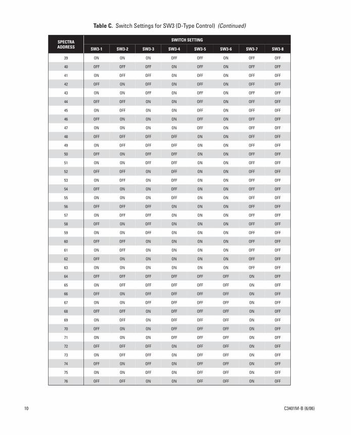
39 ON ON ON OFF OFF ON OFF OFF
40 OFF OFF OFF ON OFF ON OFF OFF
41 ON OFF OFF ON OFF ON OFF OFF
42 OFF ON OFF ON OFF ON OFF OFF
43 ON ON OFF ON OFF ON OFF OFF
44 OFF OFF ON ON OFF ON OFF OFF
45 ON OFF ON ON OFF ON OFF OFF
46 OFF ON ON ON OFF ON OFF OFF
47 ON ON ON ON OFF ON OFF OFF
48 OFF OFF OFF OFF ON ON OFF OFF
49 ON OFF OFF OFF ON ON OFF OFF
50 OFF ON OFF OFF ON ON OFF OFF
51 ON ON OFF OFF ON ON OFF OFF
52 OFF OFF ON OFF ON ON OFF OFF
53 ON OFF ON OFF ON ON OFF OFF
54 OFF ON ON OFF ON ON OFF OFF
55 ON ON ON OFF ON ON OFF OFF
56 OFF OFF OFF ON ON ON OFF OFF
57 ON OFF OFF ON ON ON OFF OFF
58 OFF ON OFF ON ON ON OFF OFF
59 ON ON OFF ON ON ON OFF OFF
60 OFF OFF ON ON ON ON OFF OFF
61 ON OFF ON ON ON ON OFF OFF
62 OFF ON ON ON ON ON OFF OFF
63 ON ON ON ON ON ON OFF OFF
64 OFF OFF OFF OFF OFF OFF ON OFF
65 ON OFF OFF OFF OFF OFF ON OFF
66 OFF ON OFF OFF OFF OFF ON OFF
67 ON ON OFF OFF OFF OFF ON OFF
68 OFF OFF ON OFF OFF OFF ON OFF
69 ON OFF ON OFF OFF OFF ON OFF
70 OFF ON ON OFF OFF OFF ON OFF
71 ON ON ON OFF OFF OFF ON OFF
72 OFF OFF OFF ON OFF OFF ON OFF
73 ON OFF OFF ON OFF OFF ON OFF
74 OFF ON OFF ON OFF OFF ON OFF
75 ON ON OFF ON OFF OFF ON OFF
76 OFF OFF ON ON OFF OFF ON OFF
Table C. Switch Settings for SW3 (D-Type Control) (Continued)
SPECTRAADDRESS
SWITCH SETTING
SW3-1 SW3-2 SW3-3 SW3-4 SW3-5 SW3-6 SW3-7 SW3-8
10 C3401M-B (6/06)

77 ON OFF ON ON OFF OFF ON OFF
78 OFF ON ON ON OFF OFF ON OFF
79 ON ON ON ON OFF OFF ON OFF
80 OFF OFF OFF OFF ON OFF ON OFF
81 ON OFF OFF OFF ON OFF ON OFF
82 OFF ON OFF OFF ON OFF ON OFF
83 ON ON OFF OFF ON OFF ON OFF
84 OFF OFF ON OFF ON OFF ON OFF
85 ON OFF ON OFF ON OFF ON OFF
86 OFF ON ON OFF ON OFF ON OFF
87 ON ON ON OFF ON OFF ON OFF
88 OFF OFF OFF ON ON OFF ON OFF
89 ON OFF OFF ON ON OFF ON OFF
90 OFF ON OFF ON ON OFF ON OFF
91 ON ON OFF ON ON OFF ON OFF
92 OFF OFF ON ON ON OFF ON OFF
93 ON OFF ON ON ON OFF ON OFF
94 OFF ON ON ON ON OFF ON OFF
95 ON ON ON ON ON OFF ON OFF
96 OFF OFF OFF OFF OFF ON ON OFF
97 ON OFF OFF OFF OFF ON ON OFF
98 OFF ON OFF OFF OFF ON ON OFF
99 ON ON OFF OFF OFF ON ON OFF
100 OFF OFF ON OFF OFF ON ON OFF
101 ON OFF ON OFF OFF ON ON OFF
102 OFF ON ON OFF OFF ON ON OFF
103 ON ON ON OFF OFF ON ON OFF
104 OFF OFF OFF ON OFF ON ON OFF
105 ON OFF OFF ON OFF ON ON OFF
106 OFF ON OFF ON OFF ON ON OFF
107 ON ON OFF ON OFF ON ON OFF
108 OFF OFF ON ON OFF ON ON OFF
109 ON OFF ON ON OFF ON ON OFF
110 OFF ON ON ON OFF ON ON OFF
111 ON ON ON ON OFF ON ON OFF
112 OFF OFF OFF OFF ON ON ON OFF
113 ON OFF OFF OFF ON ON ON OFF
114 OFF ON OFF OFF ON ON ON OFF
Table C. Switch Settings for SW3 (D-Type Control) (Continued)
SPECTRAADDRESS
SWITCH SETTING
SW3-1 SW3-2 SW3-3 SW3-4 SW3-5 SW3-6 SW3-7 SW3-8
C3401M-B (6/06) 11
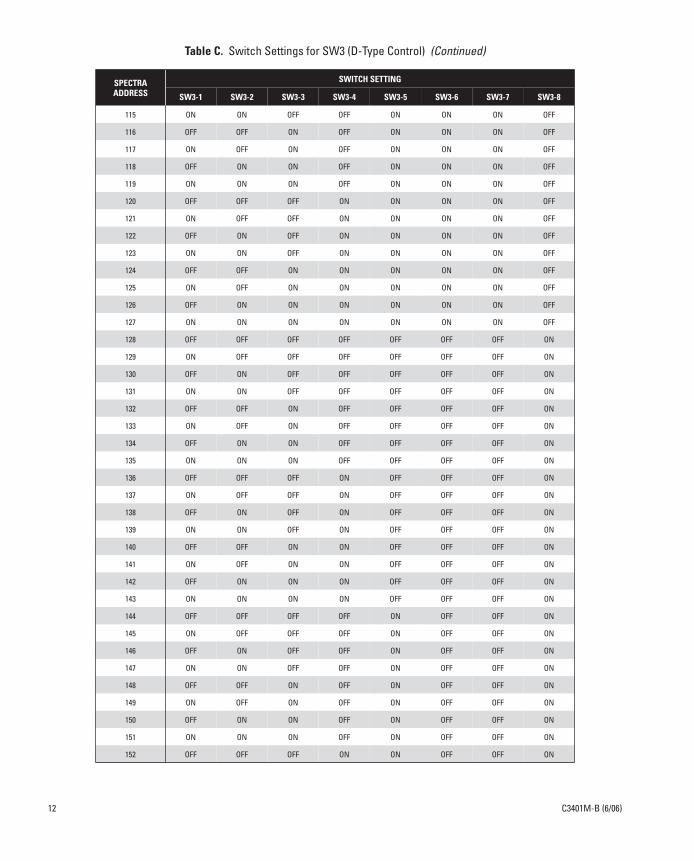
115 ON ON OFF OFF ON ON ON OFF
116 OFF OFF ON OFF ON ON ON OFF
117 ON OFF ON OFF ON ON ON OFF
118 OFF ON ON OFF ON ON ON OFF
119 ON ON ON OFF ON ON ON OFF
120 OFF OFF OFF ON ON ON ON OFF
121 ON OFF OFF ON ON ON ON OFF
122 OFF ON OFF ON ON ON ON OFF
123 ON ON OFF ON ON ON ON OFF
124 OFF OFF ON ON ON ON ON OFF
125 ON OFF ON ON ON ON ON OFF
126 OFF ON ON ON ON ON ON OFF
127 ON ON ON ON ON ON ON OFF
128 OFF OFF OFF OFF OFF OFF OFF ON
129 ON OFF OFF OFF OFF OFF OFF ON
130 OFF ON OFF OFF OFF OFF OFF ON
131 ON ON OFF OFF OFF OFF OFF ON
132 OFF OFF ON OFF OFF OFF OFF ON
133 ON OFF ON OFF OFF OFF OFF ON
134 OFF ON ON OFF OFF OFF OFF ON
135 ON ON ON OFF OFF OFF OFF ON
136 OFF OFF OFF ON OFF OFF OFF ON
137 ON OFF OFF ON OFF OFF OFF ON
138 OFF ON OFF ON OFF OFF OFF ON
139 ON ON OFF ON OFF OFF OFF ON
140 OFF OFF ON ON OFF OFF OFF ON
141 ON OFF ON ON OFF OFF OFF ON
142 OFF ON ON ON OFF OFF OFF ON
143 ON ON ON ON OFF OFF OFF ON
144 OFF OFF OFF OFF ON OFF OFF ON
145 ON OFF OFF OFF ON OFF OFF ON
146 OFF ON OFF OFF ON OFF OFF ON
147 ON ON OFF OFF ON OFF OFF ON
148 OFF OFF ON OFF ON OFF OFF ON
149 ON OFF ON OFF ON OFF OFF ON
150 OFF ON ON OFF ON OFF OFF ON
151 ON ON ON OFF ON OFF OFF ON
152 OFF OFF OFF ON ON OFF OFF ON
Table C. Switch Settings for SW3 (D-Type Control) (Continued)
SPECTRAADDRESS
SWITCH SETTING
SW3-1 SW3-2 SW3-3 SW3-4 SW3-5 SW3-6 SW3-7 SW3-8
12 C3401M-B (6/06)
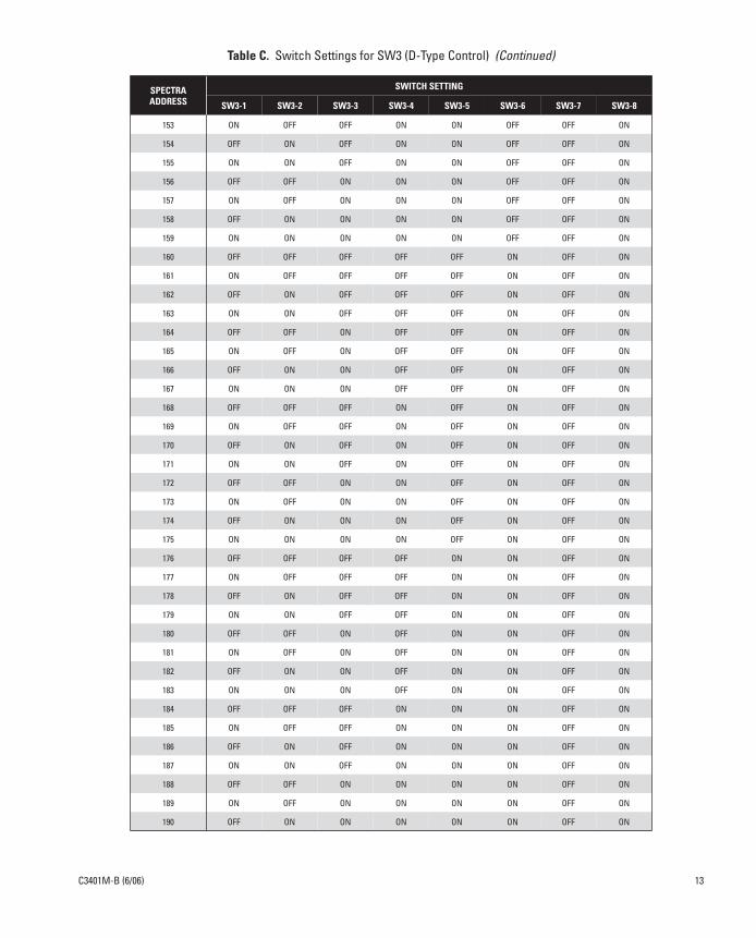
153 ON OFF OFF ON ON OFF OFF ON
154 OFF ON OFF ON ON OFF OFF ON
155 ON ON OFF ON ON OFF OFF ON
156 OFF OFF ON ON ON OFF OFF ON
157 ON OFF ON ON ON OFF OFF ON
158 OFF ON ON ON ON OFF OFF ON
159 ON ON ON ON ON OFF OFF ON
160 OFF OFF OFF OFF OFF ON OFF ON
161 ON OFF OFF OFF OFF ON OFF ON
162 OFF ON OFF OFF OFF ON OFF ON
163 ON ON OFF OFF OFF ON OFF ON
164 OFF OFF ON OFF OFF ON OFF ON
165 ON OFF ON OFF OFF ON OFF ON
166 OFF ON ON OFF OFF ON OFF ON
167 ON ON ON OFF OFF ON OFF ON
168 OFF OFF OFF ON OFF ON OFF ON
169 ON OFF OFF ON OFF ON OFF ON
170 OFF ON OFF ON OFF ON OFF ON
171 ON ON OFF ON OFF ON OFF ON
172 OFF OFF ON ON OFF ON OFF ON
173 ON OFF ON ON OFF ON OFF ON
174 OFF ON ON ON OFF ON OFF ON
175 ON ON ON ON OFF ON OFF ON
176 OFF OFF OFF OFF ON ON OFF ON
177 ON OFF OFF OFF ON ON OFF ON
178 OFF ON OFF OFF ON ON OFF ON
179 ON ON OFF OFF ON ON OFF ON
180 OFF OFF ON OFF ON ON OFF ON
181 ON OFF ON OFF ON ON OFF ON
182 OFF ON ON OFF ON ON OFF ON
183 ON ON ON OFF ON ON OFF ON
184 OFF OFF OFF ON ON ON OFF ON
185 ON OFF OFF ON ON ON OFF ON
186 OFF ON OFF ON ON ON OFF ON
187 ON ON OFF ON ON ON OFF ON
188 OFF OFF ON ON ON ON OFF ON
189 ON OFF ON ON ON ON OFF ON
190 OFF ON ON ON ON ON OFF ON
Table C. Switch Settings for SW3 (D-Type Control) (Continued)
SPECTRAADDRESS
SWITCH SETTING
SW3-1 SW3-2 SW3-3 SW3-4 SW3-5 SW3-6 SW3-7 SW3-8
C3401M-B (6/06) 13
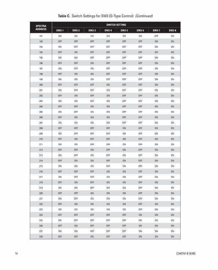
191 ON ON ON ON ON ON OFF ON
192 OFF OFF OFF OFF OFF OFF ON ON
193 ON OFF OFF OFF OFF OFF ON ON
194 OFF ON OFF OFF OFF OFF ON ON
195 ON ON OFF OFF OFF OFF ON ON
196 OFF OFF ON OFF OFF OFF ON ON
197 ON OFF ON OFF OFF OFF ON ON
198 OFF ON ON OFF OFF OFF ON ON
199 ON ON ON OFF OFF OFF ON ON
200 OFF OFF OFF ON OFF OFF ON ON
201 ON OFF OFF ON OFF OFF ON ON
202 OFF ON OFF ON OFF OFF ON ON
203 ON ON OFF ON OFF OFF ON ON
204 OFF OFF ON ON OFF OFF ON ON
205 ON OFF ON ON OFF OFF ON ON
206 OFF ON ON ON OFF OFF ON ON
207 ON ON ON ON OFF OFF ON ON
208 OFF OFF OFF OFF ON OFF ON ON
209 ON OFF OFF OFF ON OFF ON ON
210 OFF ON OFF OFF ON OFF ON ON
211 ON ON OFF OFF ON OFF ON ON
212 OFF OFF ON OFF ON OFF ON ON
213 ON OFF ON OFF ON OFF ON ON
214 OFF ON ON OFF ON OFF ON ON
215 ON ON ON OFF ON OFF ON ON
216 OFF OFF OFF ON ON OFF ON ON
217 ON OFF OFF ON ON OFF ON ON
218 OFF ON OFF ON ON OFF ON ON
219 ON ON OFF ON ON OFF ON ON
220 OFF OFF ON ON ON OFF ON ON
221 ON OFF ON ON ON OFF ON ON
222 OFF ON ON ON ON OFF ON ON
223 ON ON ON ON ON OFF ON ON
224 OFF OFF OFF OFF OFF ON ON ON
225 ON OFF OFF OFF OFF ON ON ON
226 OFF ON OFF OFF OFF ON ON ON
227 ON ON OFF OFF OFF ON ON ON
228 OFF OFF ON OFF OFF ON ON ON
Table C. Switch Settings for SW3 (D-Type Control) (Continued)
SPECTRAADDRESS
SWITCH SETTING
SW3-1 SW3-2 SW3-3 SW3-4 SW3-5 SW3-6 SW3-7 SW3-8
14 C3401M-B (6/06)

229 ON OFF ON OFF OFF ON ON ON
230 OFF ON ON OFF OFF ON ON ON
231 ON ON ON OFF OFF ON ON ON
232 OFF OFF OFF ON OFF ON ON ON
233 ON OFF OFF ON OFF ON ON ON
234 OFF ON OFF ON OFF ON ON ON
235 ON ON OFF ON OFF ON ON ON
236 OFF OFF ON ON OFF ON ON ON
237 ON OFF ON ON OFF ON ON ON
238 OFF ON ON ON OFF ON ON ON
239 ON ON ON ON OFF ON ON ON
240 OFF OFF OFF OFF ON ON ON ON
241 ON OFF OFF OFF ON ON ON ON
242 OFF ON OFF OFF ON ON ON ON
243 ON ON OFF OFF ON ON ON ON
244 OFF OFF ON OFF ON ON ON ON
245 ON OFF ON OFF ON ON ON ON
246 OFF ON ON OFF ON ON ON ON
247 ON ON ON OFF ON ON ON ON
248 OFF OFF OFF ON ON ON ON ON
249 ON OFF OFF ON ON ON ON ON
250 OFF ON OFF ON ON ON ON ON
251 ON ON OFF ON ON ON ON ON
252 OFF OFF ON ON ON ON ON ON
253 ON OFF ON ON ON ON ON ON
254 OFF ON ON ON ON ON ON ON
Table C. Switch Settings for SW3 (D-Type Control) (Continued)
SPECTRAADDRESS
SWITCH SETTING
SW3-1 SW3-2 SW3-3 SW3-4 SW3-5 SW3-6 SW3-7 SW3-8
C3401M-B (6/06) 15
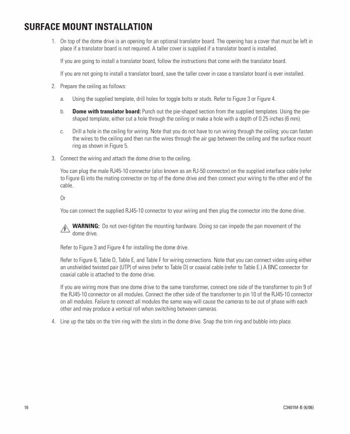
SURFACE MOUNT INSTALLATION1. On top of the dome drive is an opening for an optional translator board. The opening has a cover that must be left in
place if a translator board is not required. A taller cover is supplied if a translator board is installed.
If you are going to install a translator board, follow the instructions that come with the translator board.
If you are not going to install a translator board, save the taller cover in case a translator board is ever installed.
2. Prepare the ceiling as follows:
a. Using the supplied template, drill holes for toggle bolts or studs. Refer to Figure 3 or Figure 4.
b. Dome with translator board: Punch out the pie-shaped section from the supplied templates. Using the pie-shaped template, either cut a hole through the ceiling or make a hole with a depth of 0.25 inches (6 mm).
c. Drill a hole in the ceiling for wiring. Note that you do not have to run wiring through the ceiling; you can fasten the wires to the ceiling and then run the wires through the air gap between the ceiling and the surface mount ring as shown in Figure 5.
3. Connect the wiring and attach the dome drive to the ceiling.
You can plug the male RJ45-10 connector (also known as an RJ-50 connector) on the supplied interface cable (refer to Figure 6) into the mating connector on top of the dome drive and then connect your wiring to the other end of the cable.
Or
You can connect the supplied RJ45-10 connector to your wiring and then plug the connector into the dome drive.
Refer to Figure 3 and Figure 4 for installing the dome drive.
Refer to Figure 6, Table D, Table E, and Table F for wiring connections. Note that you can connect video using either an unshielded twisted pair (UTP) of wires (refer to Table D) or coaxial cable (refer to Table E.) A BNC connector for coaxial cable is attached to the dome drive.
If you are wiring more than one dome drive to the same transformer, connect one side of the transformer to pin 9 of the RJ45-10 connector on all modules. Connect the other side of the transformer to pin 10 of the RJ45-10 connector on all modules. Failure to connect all modules the same way will cause the cameras to be out of phase with each other and may produce a vertical roll when switching between cameras.
4. Line up the tabs on the trim ring with the slots in the dome drive. Snap the trim ring and bubble into place.
WARNING: Do not over-tighten the mounting hardware. Doing so can impede the pan movement of the dome drive.
16 C3401M-B (6/06)
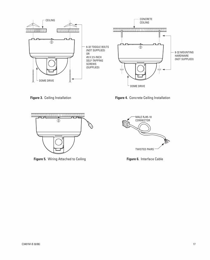
Figure 3. Ceiling Installation Figure 4. Concrete Ceiling Installation
Figure 5. Wiring Attached to Ceiling Figure 6. Interface Cable
CEILING
6-32 TOGGLE BOLTS(NOT SUPPLIED)OR#8 X 3.5-INCHSELF-TAPPINGSCREWS(SUPPLIED)
DOME DRIVE
CONCRETECEILING
8-32 MOUNTING HARDWARE(NOT SUPPLIED)
DOME DRIVE
MALE RJ45-10CONNECTOR
TWISTED PAIRS
C3401M-B (6/06) 17
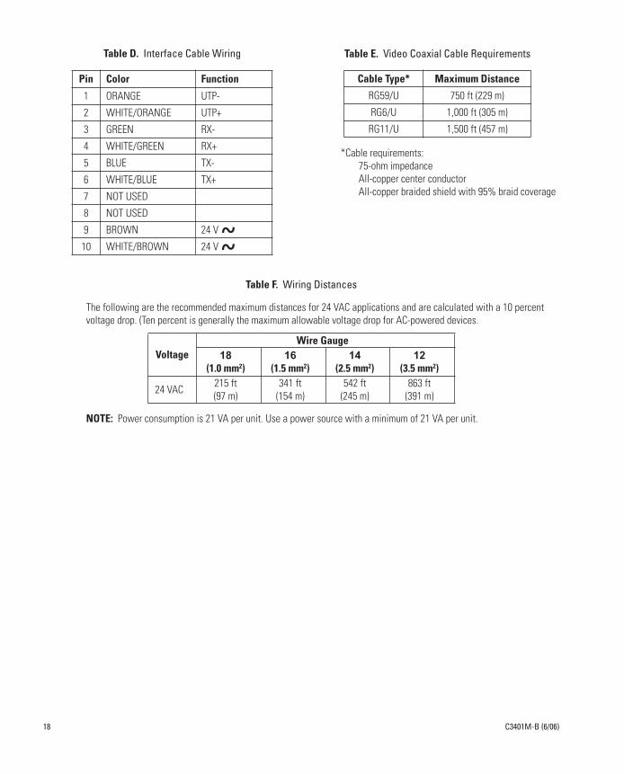
Table F. Wiring Distances
The following are the recommended maximum distances for 24 VAC applications and are calculated with a 10 percent voltage drop. (Ten percent is generally the maximum allowable voltage drop for AC-powered devices.
NOTE: Power consumption is 21 VA per unit. Use a power source with a minimum of 21 VA per unit.
VoltageWire Gauge
18(1.0 mm2)
16(1.5 mm2)
14(2.5 mm2)
12(3.5 mm2)
24 VAC 215 ft(97 m)
341 ft(154 m)
542 ft(245 m)
863 ft(391 m)
Table D. Interface Cable Wiring
Pin Color Function
1 ORANGE UTP-
2 WHITE/ORANGE UTP+
3 GREEN RX-
4 WHITE/GREEN RX+
5 BLUE TX-
6 WHITE/BLUE TX+
7 NOT USED
8 NOT USED
9 BROWN 24 V
10 WHITE/BROWN 24 V
Table E. Video Coaxial Cable Requirements
*Cable requirements:75-ohm impedanceAll-copper center conductorAll-copper braided shield with 95% braid coverage
Cable Type* Maximum Distance
RG59/U 750 ft (229 m)
RG6/U 1,000 ft (305 m)
RG11/U 1,500 ft (457 m)
18
C3401M-B (6/06)
RECESSED INSTALLATION
SUSPENDED CEILING
1. On top of the dome drive is an opening for an optional translator board. The opening has a cover that must be left in place if a translator board is not required. A taller cover is supplied if a translator board is installed.
If you are going to install a translator board, follow the instructions that come with the translator board.
If you are not going to install a translator board, save the taller cover in case a translator board is ever installed.
2. Remove the ceiling tile from the ceiling.
3. Using the supplied template, cut holes in the ceiling tile for the dome drive and mounting hardware.
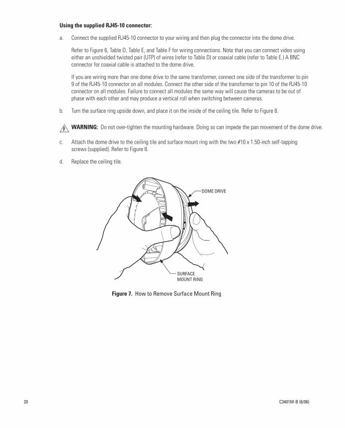
4. Remove the surface mount ring from the dome drive as follows. Refer to Figure 7.
a. Place fingers on the circular marks located on the sides of the surface mount ring.
b. Pinch the sides.
c. Lift and remove the surface mount ring from the dome drive. Do not discard the surface mount ring because it is required to complete the installation.
5. Connect the wiring and attach the dome drive to the ceiling tile.
Using the supplied interface cable:
a. Plug the male RJ45-10 connector (also known as an RJ-50 connector) on the supplied interface cable (refer to Figure 6) into the mating connector on top of the dome drive.
b. Turn the surface ring upside down, and place it on the inside of the ceiling tile. Refer to Figure 8.
c. Attach the dome drive to the ceiling tile and surface mount ring with the two #10 x 1.50-inch self-tapping screws (supplied). Refer to Figure 8.
d. Replace the ceiling tile.
e. Remove an adjacent ceiling tile, and connect your wiring to the dome drive.
Refer to Figure 6, Table D, Table E, and Table F for wiring connections. Note that you can connect video using either an unshielded twisted pair (UTP) of wires (refer to Table D) or coaxial cable (refer to Table E.) A BNC connector for coaxial cable is attached to the dome drive.
If you are wiring more than one dome drive to the same transformer, connect one side of the transformer to pin 9 of the RJ45-10 connector on all modules. Connect the other side of the transformer to pin 10 of the RJ45-10 connector on all modules. Failure to connect all modules the same way will cause the cameras to be out of phase with each other and may produce a vertical roll when switching between cameras.
WARNING: Do not over-tighten the mounting hardware. Doing so can impede the pan movement of the dome drive.
C3401M-B (6/06) 19
ve.
Using the supplied RJ45-10 connector:
a. Connect the supplied RJ45-10 connector to your wiring and then plug the connector into the dome drive.
Refer to Figure 6, Table D, Table E, and Table F for wiring connections. Note that you can connect video using either an unshielded twisted pair (UTP) of wires (refer to Table D) or coaxial cable (refer to Table E.) A BNC connector for coaxial cable is attached to the dome drive.
If you are wiring more than one dome drive to the same transformer, connect one side of the transformer to pin 9 of the RJ45-10 connector on all modules. Connect the other side of the transformer to pin 10 of the RJ45-10 connector on all modules. Failure to connect all modules the same way will cause the cameras to be out of phase with each other and may produce a vertical roll when switching between cameras.
b. Turn the surface ring upside down, and place it on the inside of the ceiling tile. Refer to Figure 8.
c. Attach the dome drive to the ceiling tile and surface mount ring with the two #10 x 1.50-inch self-tapping screws (supplied). Refer to Figure 8.
d. Replace the ceiling tile.
Figure 7. How to Remove Surface Mount Ring
WARNING: Do not over-tighten the mounting hardware. Doing so can impede the pan movement of the dome dri
DOME DRIVE
SURFACEMOUNT RING
20 C3401M-B (6/06)

Figure 8. Ceiling Tile Installation
6. Line up the tabs on the trim ring with the slots in the dome drive. Snap the trim ring and dome bubble into place.
SURFACE MOUNT RING
#10 x 1.50-INCHSELF-TAPPINGSCREWS(SUPPLIED)
DOME DRIVE
CEILINGTILE
C3401M-B (6/06) 21

HARD CEILING
1. On top of the dome drive is an opening for an optional translator board. The opening has a cover that must be left in place if a translator board is not required. A taller cover is supplied if a translator board is installed.
If you are going to install a translator board, follow the instructions that come with the translator board.
If you are not going to install a translator board, save the taller cover in case a translator board is ever installed.
2. Using the supplied template, cut holes in the ceiling for the dome drive and mounting hardware. Pull the wiring for power, video, and control through the ceiling.
3. Remove the surface mount ring from the dome drive as follows. Refer to Figure 7.
a. Place fingers on the circular marks located on the sides of the surface mount ring.
b. Pinch the sides.
c. Lift and remove the surface mount ring from the dome drive.
4. Connect the wiring.
You can plug the male RJ45-10 connector (also known as an RJ-50 connector) on the supplied interface cable (refer to Figure 6) into the mating connector on top of the dome drive and then connect your wiring to the other end of the cable.
Or
You can connect the supplied RJ45-10 connector to your wiring and then plug the connector into the dome drive.
Refer to Figure 6, Table D, Table E, and Table F for wiring connections. Note that you can connect video using either an unshielded twisted pair (UTP) of wires (refer to Table D) or coaxial cable (refer to Table E.) A BNC connector for coaxial cable is attached to the dome drive.
If you are wiring more than one dome drive to the same transformer, connect one side of the transformer to pin 9 of the RJ45-10 connector on all modules. Connect the other side of the transformer to pin 10 of the RJ45-10 connector on all modules. Failure to connect all modules the same way will cause the cameras to be out of phase with each other and may produce a vertical roll when switching between cameras.
22 C3401M-B (6/06)
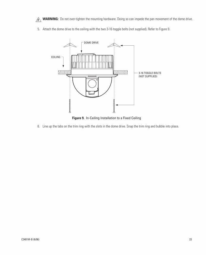
5. Attach the dome drive to the ceiling with the two 3-16 toggle bolts (not supplied). Refer to Figure 9.
Figure 9. In-Ceiling Installation to a Fixed Ceiling
6. Line up the tabs on the trim ring with the slots in the dome drive. Snap the trim ring and bubble into place.
WARNING: Do not over-tighten the mounting hardware. Doing so can impede the pan movement of the dome drive.
CEILING
3-16 TOGGLE BOLTS(NOT SUPPLIED)
DOME DRIVE
C3401M-B (6/06) 23
Specifications
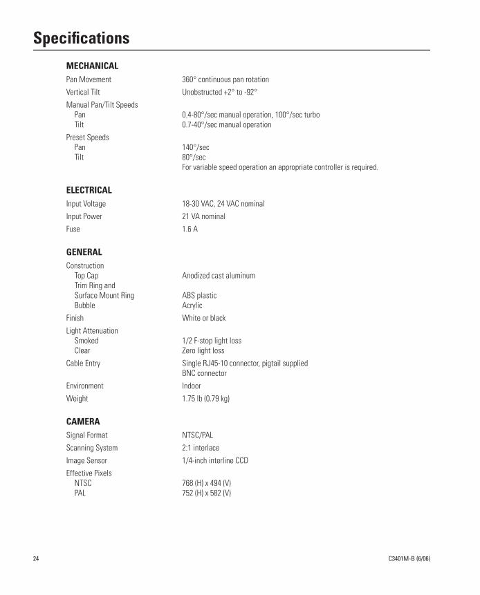
MECHANICALPan Movement 360° continuous pan rotation
Vertical Tilt Unobstructed +2° to -92°
Manual Pan/Tilt SpeedsPan 0.4-80°/sec manual operation, 100°/sec turboTilt 0.7-40°/sec manual operation
Preset SpeedsPan 140°/secTilt 80°/sec
For variable speed operation an appropriate controller is required.
ELECTRICALInput Voltage 18-30 VAC, 24 VAC nominal
Input Power 21 VA nominal
Fuse 1.6 A
GENERALConstruction
Top Cap Anodized cast aluminumTrim Ring andSurface Mount Ring ABS plasticBubble Acrylic
Finish White or black
Light AttenuationSmoked 1/2 F-stop light lossClear Zero light loss
Cable Entry Single RJ45-10 connector, pigtail suppliedBNC connector
Environment Indoor
Weight 1.75 lb (0.79 kg)
CAMERASignal Format NTSC/PAL
Scanning System 2:1 interlace
Image Sensor 1/4-inch interline CCD
Effective PixelsNTSC 768 (H) x 494 (V)PAL 752 (H) x 582 (V)
24 C3401M-B (6/06)

Horizontal ResolutionNTSC >470 TV linesPAL >460 TV lines
Minimum Illumination 3.0 lux
Sync System AC line lock, phase adjustable via remote control, V-Sync
White Balance Automatic with manual override
Shutter Speed Automatic (electronic iris)/manual1/60~1/30,000
Gain Control Automatic with manual override
Video Output 1.0 to 1.2 Vp-p, 75 ohms, adjustable
Video Signal-to-Noise Ratio >50 dB
LENSLens F1.8 (F=4.2-42 mm optical) 10X optical zoom, 8X digital zoom
Zoom Speed (optical range) 1.5/2.5/4.3 seconds
Horizontal Angle of View 46.4° wide zoom5.0° telephoto zoom
Focus Automatic with manual override
Iris Control Automatic with manual override
(Design and product specifications subject to change without notice.)
5.05(12.83)
Ø6.19(15.72)
5.27(13.39)
Ø4.25(10.80)
5.05(12.83)
Ø6.19(15.72)
5.13(13.03)
Ø4.25(10.80)
WITH TXB TRANSLATOR BOARD WITHOUT TXB TRANSLATOR BOARD
NOTE: VALUES IN PARENTHESES ARE CENTIMETERS; ALL OTHERS ARE INCHES.
C3401M-B (6/06) 25

The materials used in the manufacture of this document and its components are compliant to the requirements of Directive 2002/95/EC
This equipment contains electrical or electronic components that must be recycled properly to comply with Directive 2002/96/EC of theEuropean Union regarding the disposal of waste electrical and electronic equipment (WEEE). Contact your local dealer for procedures for recycling this equipment.
26 C3401M-B (6/06)

PRODUCT WARRANTY AND RETURN INFORMATION
WARRANTY
Pelco will repair or replace, without charge, any merchandise proved defectivein material or workmanship
for a period of one year
after the date ofshipment.
Exceptions to this warranty are as noted below:
• Five years on FR/FT/FS Series fiber optic products and TW3000 Seriesunshielded twisted pair transmission products.
• Three years on Genex
®
Series products (multiplexers, server, and keyboard).
• Three years on Camclosure
®
and fixed camera models, except theCC3701H-2, CC3701H-2X, CC3751H-2, CC3651H-2X, MC3651H-2, andMC3651H-2X camera models, which have a five-year warranty.
• Three years on PMCL200/300/400 Series LCD monitors.
• Two years on standard motorized or fixed focal length lenses.
• Two years on Legacy
®
, CM6700/CM6800/CM9700 Series matrix, and DF5/DF8 Series fixed dome products.
• Two years on Spectra
®
, Esprit
®
, ExSite
™
, and PS20 scanners, includingwhen used in continuous motion applications.
• Two years on Esprit
®
and WW5700 Series window wiper (excluding wiperblades).
• Two years (except lamp and color wheel) on Digital Light Processing (DLP
®
)displays. The lamp and color wheel will be covered for a period of 90 days.The air filter is not covered under warranty.
• Eighteen months on DX Series digital video recorders, NVR300 Seriesnetwork video recorders, and Endura
™
Series distributed network-basedvideo products.
• One year (except video heads) on video cassette recorders (VCRs). Videoheads will be covered for a period of six months.
• Six months on all pan and tilts, scanners or preset lenses used in continu-ous motion applications (that is, preset scan, tour and auto scan modes).
Pelco will warrant all replacement parts and repairs for 90 days from the dateof Pelco shipment. All goods requiring warranty repair shall be sent freightprepaid to Pelco, Clovis, California. Repairs made necessary by reason of mis-use, alteration, normal wear, or accident are not covered under this warranty.
Pelco assumes no risk and shall be subject to no liability for damages or lossresulting from the specific use or application made of the Products. Pelco’sliability for any claim, whether based on breach of contract, negligence,infringement of any rights of any party or product liability, relating to theProducts shall not exceed the price paid by the Dealer to Pelco for suchProducts. In no event will Pelco be liable for any special, incidental or conse-quential damages (including loss of use, loss of profit and claims of thirdparties) however caused, whether by the negligence of Pelco or otherwise.
The above warranty provides the Dealer with specific legal rights. The Dealermay also have additional rights, which are subject to variation from state tostate.
If a warranty repair is required, the Dealer must contact Pelco at(800) 289-9100 or (559) 292-1981 to obtain a Repair Authorization number(RA), and provide the following information:
1. Model and serial number2. Date of shipment, P.O. number, Sales Order number, or Pelco invoice number3. Details of the defect or problem
If there is a dispute regarding the warranty of a product which does not fallunder the warranty conditions stated above, please include a written explana-tion with the product when returned.
Method of return shipment shall be the same or equal to the method by whichthe item was received by Pelco.
RETURNS
In order to expedite parts returned to the factory for repair or credit, pleasecall the factory at (800) 289-9100 or (559) 292-1981 to obtain an authorizationnumber (CA number if returned for credit, and RA number if returned forrepair).
All merchandise returned for credit may be subject to a 20% restocking andrefurbishing charge.
Goods returned for repair or credit should be clearly identified with the assignedCA or RA number and freight should be prepaid. Ship to the appropriate addressbelow.
If you are located within the continental U.S., Alaska, Hawaii or Puerto Rico,send goods to:
Service DepartmentPelco3500 Pelco WayClovis, CA 93612-5699
If you are located outside the continental U.S., Alaska, Hawaii or Puerto Ricoand are instructed to return goods to the USA, you may do one of the following:
If the goods are to be sent by a COURIER SERVICE, send the goods to:Pelco3500 Pelco WayClovis, CA 93612-5699 USA
If the goods are to be sent by a FREIGHT FORWARDER, send the goods to:Pelco c/o Expeditors473 Eccles AvenueSouth San Francisco, CA 94080 USAPhone: 650-737-1700Fax: 650-737-0933
REVISION HISTORY
Manual # Date Comments
C3401M 12/05 Original version.C3401M-A 1/06 Added warning about over-tightening mounting hardware.C3401M-B 6/06 Updated model numbers and specifications to include black models.
Pelco, the Pelco logo, Camclosure, Esprit, Genex, Legacy, and Spectra are registered trademarks of Pelco.Endura and ExSite are trademarks of Pelco.DLP is a registered trademark of Texas Instruments, Inc. ©Copyright 2006, Pelco. All rights reserved.

United States
|
Canada
|
United Kingdom
|
The Netherlands
|
Singapore
|
Spain
|
Scandinavia
|
France
|
Middle East
Worldwide Headquarters3500 Pelco Way
Clovis, California 93612 USA
USA & CanadaTel: 800/289-9100Fax: 800/289-9150
InternationalTel: 1-559/292-1981Fax: 1-559/348-1120
www.pelco.com
ISO9001