Embed Size (px)
Citation preview

PEM Fuel Cell System Manufacturing Cost Analysis for Automotive Applications
Yong Yang
Austin Power Engineering LLC2310 W 9th ST UNIT 1
Austin, TX 78703USA
© 2013 Austin Power Engineering LLC
Yong Yang
President
October, 2013

Have been working on fuel cell manufacturing cost modeling for US DOE, UK Carbon Trust, and commercial clients since 2002.
Introduction Overview
US
Commercial Clients
SOFC
SOFC PEMFC DMFC Electrolyzer H2 Storage Battery
Carbon TrustPEMFC
US DOEPEMFC H2 Storage Battery
12013 YY
2002 2003 2004 2005 2006 2007 2008 2009 2010 2011 2012 2013
US DOE
TIAX
Chief Manufacturing cost model developer
Austin Power
Chief Manufacturing cost model developer
Fuel Cell Manufacturing Cost Modeling
SOFC US DOEPEMFC H2 Storage Battery

Approach Manufacturing Cost Modeling Methodology
This approach has been used successfully for estimating the cost of various technologies for commercial clients and the DOE.
Technology Assessment
Manufacturing Cost Model
Scenario Analyses
Verification & Validation
• Literature research
• Definition of system and
component diagrams
• Size components
• Develop bill-of-
materials (BOM)
• Define system value
chain
• Quote off-shelve parts
and materials
• Select materials
• Develop processes
• Technology scenarios
• Sensitivity analysis
• Economies of Scale
• Supply chain &
manufacturing system
optimization
• Cost model internal
verification reviews
• Discussion with
technical developers
• Presentations to project
and industrial partners
2
materials (BOM) • Develop processes
• Assembly bottom-up
cost model
•Develop baseline costs
optimization
• Life cycle cost analysis
and industrial partners
• Audition by
independent reviewers
Membrane8.0%
Stack Conditioning
2.7%
Seal8.4%
Balance of Stack2.4%
Bipolar Plate26.1%
GDL5.1%
Electrode41.0%
Stack Assembly6.3%
2013 YY
Anode Ink
Anode Side
Catalyst Layer
Membrane
Processes
Cathode Side
Catalyst Layer
Cathode Ink
Hot Press
Lamination
Purchased GDL
Purchased GDL
Pt
Pt
Nafion®
Ionomer
99.9% 98.5%
99.9% 98.5%
99% 98.5%
100% 98.5%99% 98.5%
99% 98.5%
100% 100%
100% 100%
100% 100%
100% 100%
100% 100%
0
10,000
20,000
30,000
40,000
50,000
60,000
70,000
80,000
3-Year TCO 5-Year TCO 10-Year TCO 15-Year TCO
To
tal
Co
st
of
Ow
ers
hip
($
)
PEMFC Plug Hybrid Vehicle
Full Battery Electric Vehicle

Combining performance and cost model will easily generate cost results, even when varying the design inputs.
Process Simulation
�Energy requirements
Conceptual Design
�System layout and
Air (POX only)
Nat. Gas
Water
FuelReformer PSA
H2-rich gas
H2-poor gas
CatalyticBurner
HeatColdWater
99.99% pure H2
Low
PressureStorage
MediumPressure
Storage
HighPressureStorage
Flow
cntrlr
Flow
cntrlrFlowcntrlr
Dispenser
To Vehicle
CO2
H2O
Compressor with intercoolers
CoolingTower
�Process cost
Process Cost Calcs
Material
Process
$0
$1
$2
$3
$4
$5
$6
$7
$8
$9
$10La
ppin
g
CM
P
Wet
ther
mal
Oxi
datio
nS
pin
Coa
ting
Wet
Etc
hing
SiO
2
DC
Spu
tterin
g N
i
RF
Sputte
ring
ES
pin
Coa
ting
Stepp
er
DC
Spu
tterin
g Ag
Stri
ppin
gS
pin
Coa
ting
Stepp
er
Dry
Etc
hing
SiO
2
DR
IE S
i
Wet
Etc
hing
SiO
2D
ry E
tchi
ng N
I
Wafe
r C
os
t ($
)
Approach Manufacturing Cost Modeling Methodology
32013 YY
�Energy requirements
�Equipment size/ specs
Product Costs
�Product cost (capital, O&M, etc.)
�System layout and equipment requirements
Capital Cost EstimatesSite Plans
�Safety equipment, site prep, land costs
�High and low volume equipment costs
�Process cost
�Material cost
Tape Cast
AnodePowder Prep
VacuumPlasmaSpray
ElectrolyteSmall Powder
Prep
ScreenPrint
CathodeSmall Powder
Prep
Sinter in Air1400C
Sinter in Air
Formingof
Interconnect
ShearInterconnect
VacuumPlasmaSpray
SlurrySpray
ScreenPrint
Slurry Spray
Slip Cast
Finish Edges
Note: Alternative production processes appear in gray to thebottom of actual production processes assumed
BrazePaint Braze
ontoInterconnect
Blanking /Slicing
QC LeakCheck
Interconnect
Fabrication
Electrolyte CathodeAnode
Stack Assembly
Fuel Station Perimeter
Electrolyzer or SMR,High-PressureCompressor
H2 High PressureCascade Storage
System
Gaseous Fuel
Dispensing Islands
Underground Piping with shared conduit
Vent
Building
Covered Fueling Island
CNG High PressureCascade Storage System
Fire Detector
Property of:
TIAX LLC
1061 De Anza Blvd.
Cupertino, CA 95014
Task 5 CNG/Hydrogen Fueling
Site Plan - Fueling Station
Hydrogen and CNG fueling station
SIZE DWG BY DWG NO REV
A Stefan Unnasch B0228 - S0022 1
SCALE 1" = 8 ft 5 Jan 2004 SHEET 1 OF 110 ft
Security FenceNG line in
0
10,000
20,000
30,000
40,000
50,000
60,000
70,000
80,000
3-Year TCO 5-Year TCO 10-Year TCO 15-Year TCO
To
tal C
ost
of
Ow
ers
hip
($)
PEMFC Plug Hybrid Vehicle
Full Battery Electric Vehicle

The bottom-up cost approach will be used to capture accurately the manufacturing costs for each fabrication step.
Approach Example Manufacturing Flow Chart
Anode Ink
Anode Side
Catalyst Layer
Membrane Hot Press Die Cut
Purchased GDL
Pt
Nafion® Stack
Bipolar
Plate
Gasket
Frame
Viton
Viton
Sheet Metal
99.9% 98.5%
99% 98.5%
100% 98.5%99% 98.5%
100% 100%
100% 98.5% 99% 95%
99% 95%
100% 100%
100% 100%
100% 100%
100% 100%
99% 95%
99.9% 100%
Testing
99.5% 100%
4
True-value-mapping analysis virtualizes costs in each fabrication step, which breaks down costs into materials, labor, capex, utility, maintenance, etc.
2013 YY
BUY
MAKE
Membrane
Processes
Cathode Side
Catalyst Layer
Cathode Ink
Hot Press
Lamination
Die Cut
MEA
MEA Continuous Fabrication Process
Purchased GDL
Pt
Nafion®
Ionomer
Stack
Assembly
Purchased Hardware
Stack Fabrication Process
Frame Seal
Molding
Process Yield
Material Utilization
99.9% 98.5%
99% 98.5%
100% 100%
100% 100%
100% 100%
100% 100%
Testing

Austin Power Engineering’s manufacturing cost models can be used to determine a fully loaded selling price to consumers at high or low volumes.
FactoryExpense
GeneralExpense
SalesExpense
Profit
Consumer
Fixed Costs
• Equipment and Plant Depreciation
• Tooling Amortization
Corporate Expenses
• Research and Development
• Sales and Marketing
• General & Administration
• Warranty
• Taxes
Approach Manufacturing Cost Structure
5
DirectLabor
DirectMaterials
Consumer Selling Price
• Tooling Amortization
• Equipment Maintenance
• Utilities
• Building
• Indirect Labor
• Cost of capital
• Overhead Labor
Variable Costs
• Manufactured Materials
• Purchased Materials
• Fabrication Labor
• Assembly Labor
• Indirect Materials
Manufacturing Cost
We assume 100% financing with an annual discount rate of 10%, a 10-year equipment life, a 25-year building life, and three months working capital.
2012 YY

Our cost assessment includes a fuel cell system, an on-board H2 storage, and a hybrid battery pack which is for a middle size passenger vehicle.
Approach Scope
• 80 kWnet StackMembraneElectrodeGDL/MPLBipolar PlateSeal & GasketBalance of Stack
• 80 kWnet StackMembraneElectrodeGDL/MPLBipolar PlateSeal & GasketBalance of Stack
• Type IV Composite Tank
• Fill Port
• High Pressure
Regulator
• Valves & Sensors
• Fittings & Piping
• Assembly & Inspection
• Type IV Composite Tank
• Fill Port
• High Pressure
Regulator
• Valves & Sensors
• Fittings & Piping
• Assembly & Inspection
PEMFC SystemPEMFC System OnOn--board H2 Storageboard H2 Storage
• Li-Ion hybrid battery
(40kW, 1.2kWh)
• Li-Ion hybrid battery
(40kW, 1.2kWh)
Hybrid BatteryHybrid Battery
Balance of Stack• BOP
Fuel ManagementThermal ManagementAir ManagementWater Management
• Balance of SystemControl BoardValves & SensorsFittings & PipingWire HarnessOthers
• Assembly, QC, and Conditioning
Balance of Stack• BOP
Fuel ManagementThermal ManagementAir ManagementWater Management
• Balance of SystemControl BoardValves & SensorsFittings & PipingWire HarnessOthers
• Assembly, QC, and Conditioning
• Assembly & Inspection• Assembly & Inspection
62013 YY
Compressed Hydrogen Storage
PEM Fuel Cell System
Li-Ion Battery Pack
Fuel Cell Hybrid Electric Vehicle Power System

The 80 kWnet direct hydrogen PEM fuel cell system configuration was referenced in previous and current studies conducted by Argon National Laboratory (ANL).
PEMFC System 80 kWnet PEM Fuel Cell System Preliminary System Design
Key ParametersStack• 3M NSTFC MEA• 25 µm supported membrane• 0.196 mg/cm2 Pt• Power density: 984 mW/cm2
• Metal bipolar plates• Non-woven carbon fiber GDL
Air Management
7
1. DOE Fuel Cell Technologies Program Record , “Fuel Cell System Cost -2012”2. R. K. Ahluwalia, X. Wang, and R. Kumar, “Fuel cells systems analysis,” 2012 DOE Hydrogen Program Review, Washington DC, May 14-18, 2012.
25 W DMFC system configuration1, 2
80 kWnet Fuel Cell System Schematic1
Air Management• Honeywell type compressor /expender• Air-cooled motor / Air-foil bearing
Water Management• Cathode planar membrane humidifier with pre-cooler• No anode humidifier
Thermal Management• Micro-channel HX
Fuel Management• Parallel ejector / pump hybrid
2013 YY

Based on ANL’s stack performance analysis, we made the following system and material assumptions for the cost estimation.
System Assumptions 80 kWnet PEM Fuel Cell System Preliminary Design
Stack ComponentsStack Components UnitUnit Current SystemCurrent System CommentsComments
Production volume systems/year 500,000 High volumeStacks’ net power kW 80 DOE 2012Stacks’ gross power kW 88 DOE 2012Cell power density mW/cm2 984 DOE 2012Peak stack temp. Degree C 87 DOE 2012Peak stack pressure Bar 2.5 DOE 2012System Voltage (rated power) Volt 300 DOE 2012Platinum price $/tr.oz. $1,100 DOE 2012
8
Platinum price $/tr.oz. $1,100 DOE 2012Pt loading mg/cm2 0.196 DOE 2012Membrane type Reinforced 3M PFSAMembrane thickness micro meter 25GDL layer None-woven carbon paperGDL thickness micro meter 185 @50 kPa pressureMPL layer thickness micro meter 40
Bipolar plate type76Fe-20Cr-4V with
nitridation surface treatmentBipolar plate base material Thickness
micro meter 100
Seal material Viton®
Pt price was $1,100/tr.oz. for the baseline, which was consistent with other DOE cost studies.
2013 YY
We assumed a double-side dispersion coating process (US 2008/0269409) to an ePTFE-supported membrane process.
80 kWnet PEMFC System Stack Membrane Configuration & Process
ePTFE 3M PFSA Supported Membrane
Thickness (µm) 25 25
Porosity (%) 95% -
Bulk Density (g/cm3) 0.098 1.97
Material Cost $5/m2 3M Ionomor:$80/lbs** DOE FCTT feedback
9
Unwind ePTFE Film
Splicer
Guide
Cartridge
Coater
Cooling Gauge Quality
Control
Laminating
Guide
Unwind
PP Film
Winding With Roll Changer
Packaging
Splicer
Gauge Microwave Annealing /
Dryer
Bottom ePTFE Film Coating
Top ePTFE Film Coating
2013 YY

Capital Costs7.0%
Equipment & Tooling4.7%
Others2.4%
Labor Cost0.9%
The reinforced 25 µm 3M PFSA membrane is estimated to cost ~$19/m2 on an active area basis, with materials representing ~85% of the cost.
Membrane Manufactured CostMembrane Manufactured Cost11
ComponentComponent MaterialMaterial ProcessProcess
($/m($/m22)) ($/kg)($/kg) ($/m($/m22)) ($/kg)($/kg)
Film Handling $6.33 $107.64 $0.34 $5.78
Coating $10.07 $171.11 $0.44 $7.42
Drying & Cooling $0.00 $0.00 $1.98 $33.64
Membrane Manufactured Cost ($Membrane Manufactured Cost ($19/m19/m22) )
80 kWnet PEMFC System Stack Membrane Cost
Material Cost85.0%
7.0%$0.00 $0.00 $1.98 $33.64
Quality Control $0.00 $0.00 $0.04 $0.60
Laminating $0.00 $0.00 $0.05 $0.93
Packaging $0.03 $0.43 $0.03 $0.46
Subtotal $16.42 $279.19 $2.87 $48.83
Total 19.30 ($/m2)
328.02 ($/kg)
1 Manufactured cost on an active area basis or per kg of finished membrane basis (accounts for scrap and yield)
2 3M PFSA ionomer cost assumed to be $80/lb based on FCTT feedback. 3 ePTFE cost assumed to be $5/m2
102013 YY

Organic whisker support was fabricated by physical vapor deposition (PVD) with vacuum annealing process. Catalysts were coated to this layer via vacuum sputtering process.
Perylene Red
PR-149
Pre-soak
Phase I
Aluminum Coated Film Substrate
Pre-soak
Phase IIPVD
Annealing
Sputtering Sputtering SputteringSputtering Sputtering
Growing Whisker Layer
80 kWnet PEMFC System Stack Electrodes Configuration & Process
Pt Co MnPt Pt
Using three Pt targets
Nanostructured Thin Film Catalyst before transfer to a PEM2
1 M. K. Debe, Advanced Cathode Catalysts and Supports for PEM Fuel Cells, DOE Merit Review, May 20122 M. K. Debe, Durability Aspects of Nanostructured Thin Film Catalysts for PEM Fuel Cells, ECS Transactions, 1(8) 51-66 (2006)
11
Pt Whisker Distribution1
2013 YY

The 2012 electrode cost estimate of $86/m2 which was dominated by Platinum price. We have assumed Pt price to be $1,100/tr.oz. or $35.4/g.
Manufactured Manufactured CostCost
AnodeAnode11
($/m($/m22))CathodeCathode11
($/m($/m22))TotalTotal11
($/m($/m22))
Material $25.97 $50.33 $76.30
Capital Cost $1.79 $2.94 $4.73
Labor $0.16 $0.19 $0.35
Tooling $1.18 $1.75 $2.93
Other2$0.53 $0.76 $1.29
Electrode Manufactured Cost Electrode Manufactured Cost ($86/m($86/m22) )
Labor Cost0.4%
Tooling & Equip.3.4% Others
1.5%
Captial Cost5.5%
80 kWnet PEMFC System Stack Electrodes Cost
Other2$0.53 $0.76 $1.29
Total $29.63 $55.97 $85.60 1 m2 of active area2 Other costs include utilities, maintenance, and building
12
Material Cost89.1%
2013 YY

We cost a non-woven carbon paper GDL with MPL based on discussions with formerly Ballard Material Products on their AvCarb® GDS3250 for automotive applications.
Material Pressure (kPa)
Bare GDL GDL with PTFE Treatment
GDL with PTFE Treatment + MPL
Thickness (µm) 50 185 225
Porosity (%) 250 90% 88% 80%
Areal Weight (g/m2)
40 44 75
Materials Carbon Fiber loading: 15 /m2 10 wt% PTFE; PTFE loading: 15 g/m2
80 kWnet PEMFC System Stack GDL + MPL Configuration & Process
13
Mixing Carbon Fiber Solution
Carbon Paper Making
Ink/Resin Impregnation
In Line Inspection
Oxidation Carbonization
GraphitizationIn Line
InspectionHydrophobic Treatment
MPL Metering Coating
(2 wet layers)Inspection
Mixing PTFE Solution
Mixing MPL Solution
Materials Carbon Fiber loading: 15 /m2
Ink/Resin loading: 25 g/m2
10 wt% PTFE;4 g/m2
PTFE loading: 15 g/m2
Carbon black loading: 16 g/m2
2013 YY

The non-woven carbon paper GDL (for both anode and cathode) cost about $12/m2, on an active area basis.
Manufactured Manufactured CostCost11
GDLGDL($/m($/m22))
GDL (Anode + GDL (Anode + Cathode) ($/mCathode) ($/m22))
Material $0.88 $1.76
Capital Cost $1.86 $3.71
Labor $0.31 $0.63
Tooling $1.88 $3.76
GDL Manufactured Cost ($12/mGDL Manufactured Cost ($12/m22))
Material Cost15.0%
Capital Costs
Others16.0%
80 kWnet PEMFC System Stack GDL + MPL Costs
Other2$0.94 $1.88
Total $5.87 $11.73
1 Manufactured cost on an active area basis2 Other costs include utilities, maintenance, and building
14
Equipment & Tooling32.0%
Labor Cost5.4%
31.7%
2013 YY

The anode and cathode organic whisker layers were hot pressed to the membrane with Teflon® backing sheets. GDL layers were laminated to the coated membrane and were formed an MEA in roll good form. The MEA was cut into sheets and molded with a frame seal.
Anode Side
Teflon Sheet
Anode Side
Catalyst Layer
Anode Side
GDL
80 kWnet PEMFC System Stack MEA Assembly Process
Membrane
Cathode Side
Teflon Sheet
Cathode Side
Catalyst Layer
Hot Press
Lamination
Hot Press
Lamination
Cathode Side
GDL
Peel PTFE
Sheets
Die Cut
MEA
Mold
Frame Seal
Continuous Process
Batch Process
152013 YY

The MEA with frame seal together were estimated to cost about $128/m2.
Manufactured CostManufactured Cost11 MEAMEA($/m($/m22))
Frame Seal Frame Seal ($/m($/m22))
Material- Membrane- Electrode- GDL
94.48- 16.42- 76.30- 1.76
$6.07
Capital Cost $9.80 $1.71
MEA & Seal Manufactured Cost ($MEA & Seal Manufactured Cost ($128/m128/m22))
Labor1.9%
Tooling & Equip.7.1%
Others3.4%
Captial Cost
80 kWnet PEMFC System Stack MEA + Frame Seal Costs
$9.80 $1.71
Labor $1.15 $1.24
Tooling & Equipment $7.60 $1.46
Other2$3.63 $0.70
Subtotal $116.65 $11.17
Total 127.83
1 Manufactured cost on a per m2 of active area basis2 Other costs include utilities, maintenance, and building3 Active area to Total area ratio reduced from 85% to 75%, based on feedback from OEMs and FCTT
16
Material78.7%
9.0%
2013 YY

The metal bipolar plate cost was based on discussions with ORNL on their thermal nitriding process1 for specific alloys, e.g. Fe-20Cr-4V.
Coolant Channel
0.9
m
m
Cathode Side
0.65 mm
1.00 mm
0.3
5m
m0.3
5m
m
ParameterParameter SpecificationsSpecifications
Base Material Thickness (mm) 0.1
Base Material 76Fe-20Cr-4V
Base Material Surface TreatmentPre-oxidation +
Thermal Nitridation
# of Tiles in a Pair of Bipolar Plate 2
Cooling Channel Yes
Anode Side
80 kWnet PEMFC System Stack Thermal Nitrided Metal Bipolar Plate
17
Seven-Stage Progressive Die2,3
1. Nitrided metallic bipolar plates, M.P. Brady, et al., ORNL, DOE Merit Review presentation, May 20092. US 20090081520 (Hitachi)3. Discussion with Minster Press Inc., April 2010 4. Preferential thermal nitridation to form pin-hole free Cr-nitrides to protect proton exchange membrane fuel cell metallic bipolar plates, M.P. Brady, et al.,
Scripta Materialia 50 (2004) 1017-1022
Joint MethodSpot + Edge
Laser Welding
2013 YY
Stamping
Half Plate
Laser Welding
Whole Plate
Thermal
Nitridation4
Fe20Gr4V Foil100 micro meterAssume $5/lbs

The cost of the nitrided Fe-20Cr-4V metal bipolar plates was estimated to be ~$57/m2 or ~$6/kW.
Bipolar Plate Bipolar Plate Manufactured Manufactured CostCost11 ($/m($/m22))
Bipolar Plate Bipolar Plate Manufactured Manufactured CostCost22 ($/kW)($/kW)
ComponentComponent MaterialMaterial ProcessProcess MaterialMaterial ProcessProcess
Stamping $25.02 $11.06 $2.78 $1.23
Laser Welding $0.00 $8.73 $0.00 $0.97
Bipolar Plate Manufactured Bipolar Plate Manufactured Cost ($Cost ($57/m57/m22))
80 kWnet PEMFC System Stack Thermal Nitrided Metal Bipolar Plate Cost
Material Cost43.7%
Equipment & Tooling16.3%
Others10.5%
As a based material, Fe-20Cr-4V is a specialty metal and could have higher price than the conventional base materials, such as SS316, etc.
Nitridation $0.00 $12.47 0.00 $1.39
Subtotal $25.02 $32.26 $2.78 $3.58
Total $57.28 $6.36
1 Manufactured cost on an active area basis2 Manufactured cost on a kWnet basis
18
43.7%
Capital Costs17.8%
Labor Cost11.7%
2013 YY

The cost of the gasket was estimated to be ~$7/m2.
Manufactured Manufactured CostCost11
GasketGasket($/m($/m22))
Material $0.62
Capital Cost $1.93
Labor $1.26
Tooling $1.86
Other2$1.18
Gasket Gasket Manufactured Cost ($7/mManufactured Cost ($7/m22))
80 kWnet PEMFC System Stack Gasket Cost
Material Cost9.0%
Capital Costs28.2%
Others17.2%
Other2$1.18
Total $6.85
Transfer molding was used to fabricate the seals between the MEA and bipolar/cooling plate. The seal material is Viton® which costs ~$20/lb.
1 Manufactured cost on an active area basis2 Other costs include utilities, maintenance, and building
19
Equipment & Tooling27.1%
Labor Cost18.5%
2013 YY

The 80 kWnet PEM fuel cell stack cost $24/kW. Electrodes, bipolar plates, and membranes were the top three cost drivers.
80 kW80 kWnet net PEM Fuel Cell Stack Cost PEM Fuel Cell Stack Cost ($23.9/($23.9/kWkWnetnet))
Stack Stack ComponentsComponents
Stack Stack ManufacturinManufacturing Cost ($/kW)g Cost ($/kW)
CommentsComments
Membrane $2.14 PFSA ionomer ($80/lb)
Electrode $9.51 3M NSTFC
GDL $1.30 No-Woven carbon
paper
Bipolar Plate $6.36 Nitrided metallic plates
80 kWnet PEMFC System Stack Cost
Membrane9.0%
Stack Conditioning
2.5%
Seal8.4%
Balance of Stack2.3%
Stack Assembly5.8%
20
Bipolar Plate $6.36 Nitrided metallic plates
Seal $2.00 Viton
BOS $0.55
Manifold, end plates, current collectors,
insulators, tie bolts, etc.
Final Assembly $1.40 Robotic assembly
Stack Conditioning 0.60
2 Hours
Total stack2 23.85
1. Stack assembly cost category included MEA assembly and stack QC; QC included visual inspection, and leak tests for fuel, air, and coolant loops.2. Results may not appear to calculate due to rounding of the component cost results.
2013 YY
Bipolar Plate26.7%
GDL5.5%
Electrode39.9%

The water management system OEM cost1,2 was projected to be $128.
ComponentComponentFactory Factory CostCost11
OEM OEM CostCost1,21,2
Cathode Planar Membrane Humidifier
112 128
80 kWnet PEMFC System BOP Water Management System Cost
The cathode planar membrane humidifier cost was estimated using bottom-up costing tools.
1 R. K. Ahluwalia and X. Wang, Automotive Fuel Cell System with NSTFC Membrane Electrode Assemblies and Low Pt Loading, July 21, 2009
2 High-volume manufactured cost based on a 80 kW net power PEMFC system. Does not represent how costs would scale with power (kW).
3 Assumes 15% markup to the automotive OEM for BOP components
212013 YY

The thermal management system OEM cost1,2 was projected to be $404.
ComponentComponentFactory Factory CostCost11
OEM OEM CostCost1,21,2
HT Radiator 86 99
LT Radiator 21 25
Air Precooler - 20
HT/LT Radiator Fan
- Motor
- Fan
-
-
-
75
- 60
- 15
80 kWnet PEMFC System BOP Thermal Management System Cost
The air precooler, radiator fan, coolant pumps, and their motors were assumed to be purchased components; hence their price included a markup.
HT Coolant Pump
- Motor
- Pump
-
-
-
150
- 95
- 55
LT/Air Precooler Coolant Pump
- 30
Other - 5
Total 387 4041 High-volume manufactured cost based on a 80 kW net power PEMFC system. Does not represent how costs would scale with power (kW). 2 Assumes 15% markup to the automotive OEM for BOP components
22
Radiator StructureUS Patent 7,032,656
2013 YY

The fuel management system OEM cost1,2 was projected to be $382.
ComponentComponentFactory Factory CostCost11
OEM OEM CostCost1,21,2
H2 Blower 219.5 252
H2 Ejectors - 20
H2 Demister - 61
Solenoid Valves
- 23
Purge Valve 13 15
80 kWnet PEMFC System BOP Fuel Management System Cost
The H2 ejectors, H2 demister, and solenoid valves were assumed to be purchased components; hence their price included a markup.
Purge Valve 13 15
Check valve 9 10
Total 346 382
1 High-volume manufactured cost based on a 80 kW net power PEMFC system. Does not represent how costs would scale with power (kW). 2 Assumes 15% markup to the automotive OEM for BOP components
23
Parker Hannifin Brochure for Model 55 Univane™ Compressor
2013 YY

The air management system OEM cost1,2 was projected to be $936.
ComponentComponentFactory Factory CostCost11
OEM OEM CostCost1,21,2
CEM (Compressor, Expander, Motor, Motor Controller
535 615
Air demister - 156
Air/H2 mixer - 27
80 kWnet PEMFC System BOP Air Management System Cost
The air demister, air/H2 mixer, flow orifice, and air filter were assumed to be purchased components; hence their price included a markup.
Flow orifice - 5
Air filter - 4
Total - 936
1 High-volume manufactured cost based on a 80 kW net power PEMFC system. Does not represent how costs would scale with power (kW). 2 Assumes 15% markup to the automotive OEM for BOP components
24
CEM: Honeywell, DOE Program Review, Progress Report & Annual Report, 2005
2013 YY

80 kW80 kWnet net PEM Fuel Cell System PEM Fuel Cell System Cost ($4,256/system)Cost ($4,256/system)
The 80 kWnet PEM fuel cell system cost $53/kW at the mass production volume. Stack, air management, and thermal management were the top three cost drivers.
System System ComponentsComponents
System System Manufacturing Manufacturing
Cost ($/kW)Cost ($/kW)CommentsComments
Stack $23.87
Water management$1.6
Cathode side humidifier, etc.
Thermalmanagement $5.0
HX, coolant pump, etc.
80 kWnet PEMFC System System Cost
Stack44.8%
Fuel Management9.0%
Balance of System7.3%
System Assembly7.4%
25
management $5.0HX, coolant pump, etc.
Air management $10.1 CEM, etc.
Fuel management $4.8 H2 pump, etc.
Balance of system$3.9
Sensors, controls, wire harness, piping, etc.
System assembly $3.9
Total system1, 2 $53.2
1. Assumed 15% markup to the automotive OEM for BOP components2. Results may not appear to calculate due to rounding of the component cost results.
The 80 kWnet direct hydrogen PEM fuel cell system cost $4,256 at the mass production volume.
2013 YY
Water Management
3.0%Thermal
Management9.5%
Air Management19.0%

The 5,000 PSI type IV compressed hydrogen tank design was referenced in studies TIAX conducted on hydrogen storage1, 2.
Key ParametersSystem• Pressure: 5,000 PSI• Single Tank Design• Usable H2: 5.6 kg• Safety Factor: 2.25
Tank• Carbon Fiber: Toray T700S• Carbon Fiber Cost: $12/lbs• Carbon Fiber / Resin Ratio: 0.68 :
CompressedGaseousHydrogen
Tank
RefuelingInterface
Hydrogen Line
Data & Comm. Line
FillingStation
Interface
Solenoid Valve (Normally Closed)
PrimaryPressure Regulator
PressureReliefDevice
Pre
ssu
reT
ran
sd
ucer
Tem
pera
ture
Tra
nsd
ucer
PressureReliefValve
Check Valve
in Fill Port
In-Tank Regulator
Compressed H2 Storage System Configuration
26
1. E. Carlson and Y. Yang, “Compressed hydrogen and PEM fuel cell system,” Fuel cell tech team freedomCar, Detroit, MI, October 20, 2004.
2. S. Lasher and Y. Yang, “Cost analysis of hydrogen storage systems - Compressed Hydrogen On-Board Assessment – Previous Results and Updates for FreedomCARTech Team”, January , 2007
Compressed Hydrogen Storage System Schematic1, 2
The single tank design had a usable hydrogen storage capacity of 5.6 kg.
• Carbon Fiber / Resin Ratio: 0.68 : 0.32 (weight)• Translational Strength Factor: 81.5%• Fiber Process: Filament Winding• Liner: HDPE
Pressure Regulator• In-tank
*Schematic based on both the requirements defined in the draft European regulationfor “Hydrogen Vehicles: On-board Storage Systems” and US Patent 6,041,762.
**Secondary Pressure Regulatorlocated in Fuel Control Module.
FillSystemControlModule
Hydrogen Line to Fuel Control Module**
Data & Comm. Line to Fuel Cell Stack
Ball Valve
Check Valve
2013 YY

Assumptions for the hydrogen storage tank design were based on the literature review and third-party discussions.
Stack ComponentsStack Components UnitUnit Current SystemCurrent System CommentsComments
Production volume systems/year 500,000 High VolumeUsable hydrogen Kg 5.6Recoverable H2 in the tank IV With HDPE linerTank type IV With HDPE linerTank pressure PSI 5,000# of tanks Per System 1Safety factor 2.25Tank length/diameter ratio 3:1Carbon fiber type Toray T700S
Compressed H2 Storage System Specification
27
Carbon fiber type Toray T700SCarbon fiber cost $/lbs 12Carbon fiber vs. resin ratio 0.68:0.32 Weight Carbon fiber translationalStrength factor
81.5%
Damage resistant outer layer material
S-GlassCould be replaced by cheaper E-glass
S-Glass cost $/lbs 7
Impact resistant end domematerial
Rigid Foam
Rigid foam cost $/kg 3Liner material HDPELiner thickness Inch 1/4In tank regulator cost $/unit 150
2013 YY

A vertically integrated manufacturing process was assumed for the tank and BOP components.
HDPE Carbon FiberGel
• In-tank primary pressure regulator
• Valves & sensors
• Filling interface
• Pressure release devices
• Piping & fitting
Major Tank Major Tank ComponentsComponents Major BOP Major BOP ComponentsComponents
• Aluminum End Boss
• HDPE liner
• Carbon fiber composite layer
• Glass fiber composite layer
• End domes (rigid foam)
Compressed H2 Storage System Manufacturing Process
28
Liner
Molding
Pressure
liner
Liner
Surface
Gel Coat
CF
PrePreg
Filament
Winding
Cure /
Cool
down
Ultrasonic
Inspection
Glass
Fiber
Out Layer
Winding
End
Domes
Assembly
Pressure
Test
Dimension
Weight
Inspection
Cure /
Cool
down
BOP
Assembly
Boss
Machining
Final
Inspection
Al
Stock
Glass
Fiber
Rigid
Foam
BOP
Components
2013 YY
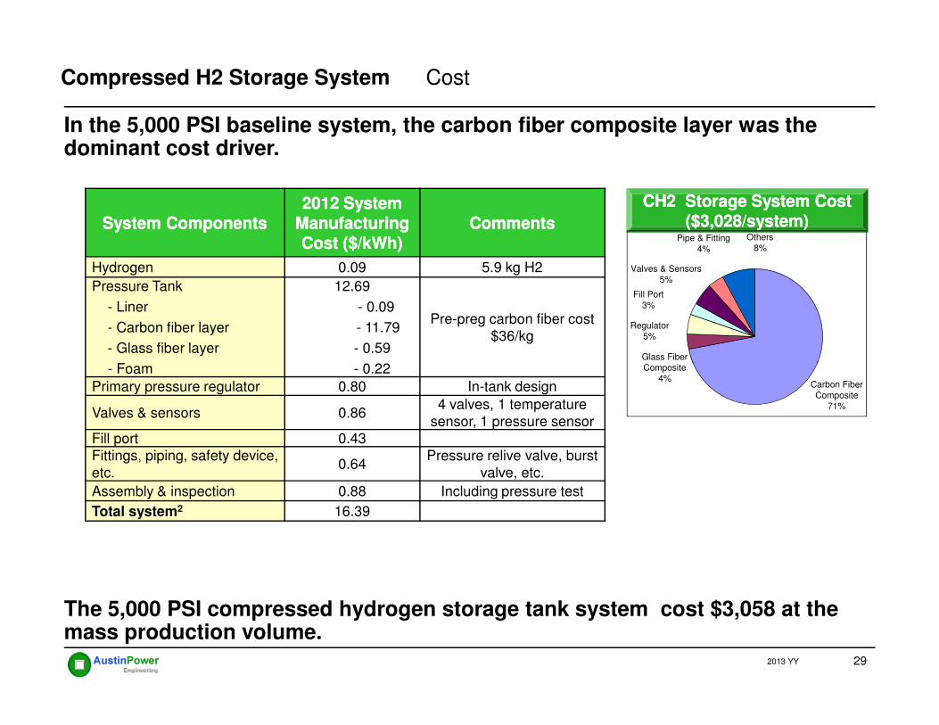
CH2 Storage System Cost CH2 Storage System Cost ($3,028/system)($3,028/system)
In the 5,000 PSI baseline system, the carbon fiber composite layer was the dominant cost driver.
System ComponentsSystem Components2012 System 2012 System
Manufacturing Manufacturing Cost ($/kWh)Cost ($/kWh)
CommentsComments
Hydrogen 0.09 5.9 kg H2
Pressure Tank
- Liner
- Carbon fiber layer
- Glass fiber layer
- Foam
12.69
- 0.09
- 11.79
- 0.59
- 0.22
Pre-preg carbon fiber cost $36/kg
Regulator5%
Valves & Sensors5%
Fill Port3%
Pipe & Fitting4%
Others8%
Glass Fiber Composite
Compressed H2 Storage System Cost
29
- Foam - 0.22
Primary pressure regulator 0.80 In-tank design
Valves & sensors 0.864 valves, 1 temperature
sensor, 1 pressure sensorFill port 0.43Fittings, piping, safety device, etc.
0.64Pressure relive valve, burst
valve, etc.
Assembly & inspection 0.88 Including pressure test
Total system2 16.39
Carbon Fiber Composite
71%
Composite4%
The 5,000 PSI compressed hydrogen storage tank system cost $3,058 at the mass production volume.
2013 YY

Low Voltage
Ba
ttery
Ma
na
ge
me
nt S
ys
tem
s
Key ParametersSystem• Power: 40 kW • Energy capacity: 1.2 kWh usable • Power to energy ratio: 33:1• Percent SOC: 80%• Fade: 20%
Th
erm
al M
an
ag
em
en
t Sys
tem
Lithium-ion Battery Pack
Battery Modules
PEMFC Hybrid Energy Storage Lithium-ion Battery Pack
A lithium-ion battery pack will provide hybridization of a fuel cell vehicle which will improves fuel economy as well as having the function as a startup battery.
30
Voltage Monitorin
g
High Voltage System
Ba
ttery
Ma
na
ge
me
nt S
ys
tem
s
(BM
S)
BOP
Cell• Cell format: Pouch cell• Cathode active Material: manganese spinel•Anode active material: graphite
Th
erm
al M
an
ag
em
en
t Sys
tem
1. US patent 201002479992. US patent 20090169990Battery
Cells2
2013 YY
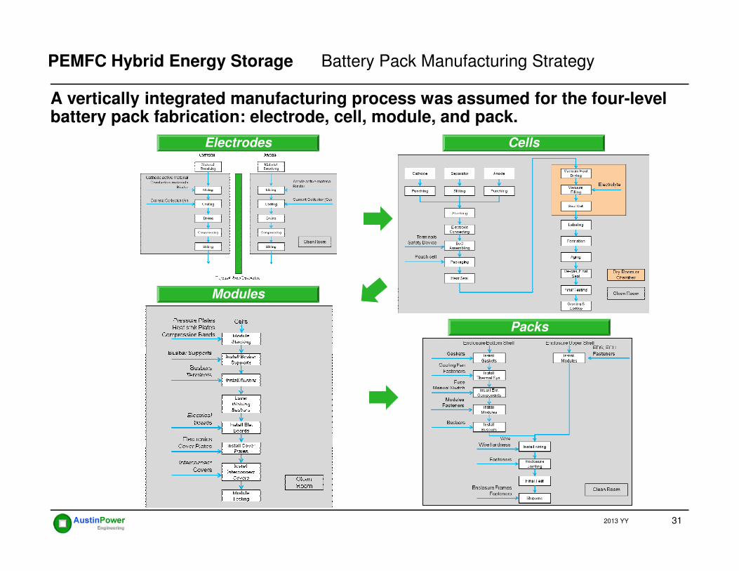
A vertically integrated manufacturing process was assumed for the four-level battery pack fabrication: electrode, cell, module, and pack.
Electrodes Cells
PEMFC Hybrid Energy Storage Battery Pack Manufacturing Strategy
31
Modules
Packs
2013 YY

The lithium-ion battery system cost $862 /kWh. Battery management system and packaging have higher cost contributions.
Battery System Cost ($862 /kWh)Battery System Cost ($862 /kWh)Cost CategoryCost Category
Cell Cost Cell Cost ($/cell)($/cell)
Pack Cost Pack Cost ($/pack)($/pack)
Material $7.88 $775
Labor $1.51 $116.96
Equipment & tooling
$1.38 $48.03
PEMFC Hybrid Energy Storage Battery Pack Cost
Labor
11%
Capex
5%
Utility
3%
Maintenance
2%Capital
4% building
0%
32
The 1.2 kWh lithium-ion battery system cost $1,034 per pack at the mass production volume.
Utility $0.79 $26.76
Maintenance $0.67 $23.79
Capital cost $1.18 $37.85
Building $0.15 $5.72
Total $13.56 $1,033.83
Total ($/kWh)* $327.63 $861.52
* Based on usable energy (1.88 kWh x 0.8 x0.8 = 1.2 /kWh )
2013 YY
Materials &
Purchased
Components
75%

The overall PEM fuel cell system, onboard hydrogen storage, and hybrid battery costs are approximately $8,318 per vehicle.
Conclusion
Compressed Hydrogen Storage
PEM Fuel Cell System
Li-Ion Battery Pack
$4,256/system$3,028/System
$1,034/systemPEM Fuel Cell
System
51%Compressed
Li-ion Battery
Pack
13%
33
• The mass production manufacturing cost of the 80 kWnet PEMFC stack was estimated to be $23.8/kW.
• The mass production OEM cost of the 80 kWnet PEMFC system was estimated to be $53.2/kW
• The 5.6kg compressed on-board hydrogen storage system was estimated to be $16.4/kWh at the mass production.
• The hybrid lithium-ion battery (40kW, 1.2kWh) costs $1,034 per pack.
2013 YY
51%Compressed
Hydrogen
Storage System
36%

Thank You!
Contact: Yong YangAustin Power Engineering LLC
34
Austin Power Engineering LLC2310 W 9th ST #1, Austin TX 78703
2013 YY