Embed Size (px)
Citation preview
1-7267
HYPERSONIC PERFORMANCE ,STABILITY , AND CONTROL OF
MANNED SPACE SHUTTLE CANDIDATES
by
William C. Woods, James P. Arrington, and David R. 'Stone
NASA Langley Research Center Hampton, Virginia
Presented at the 48th Annual Meeting of the ViTginia Academy of Science
May 5-8, 1970 Richmond, Virginia
PEN00065

HYPERSONIC PERFORMANCE, STABILITY, AND CONTROL OF
MANNED SPACE SHUTTLE CANDIDATES
by
William C. Woods, * James P. Arrington, * and David R. Stone*
NASA Langley Research Center Hampton, Virginia
ABSTRACT
The results of analytical and experimental studies to determine
the hypersonic performance, stability, and control characteristics of
vehicles representative of three proposed space shuttle designs -- fixed
straight wing, fixed delta wing, and lifting body -- are presented. In
addition, summary results of flow visualization studies utilizing the
electron beam technique are presented, and, in one instance, an anomaly
in the experimental measurements is related to flow interferep.ce patterns
illustrated by these studies.
In general~ the results being presented indicate these configurations
are capable of achieving their design performance; however, both the force
and moment data &~d the flow visualization results indicate the existence
of flow interference problem areas which require more detailed study. Per-
formance predictions, particularly at angles of attack near CL,max are quite
sound, but trim and stability predictions are shown to be meaningless.
*Aerospace Technologist, Aerospace/Operations Analysis Section, Vehicle
Analysis Branch, Space Systems Research Division

-1-
INTRODUCTION
Analytical and experimental hypersonic performance, stability, and
control studies have for the last few years, focused primarily on high per
formance configurations designed for some particular maximum range and
consequently operating at angles of attack near that required for (L/D)max
(refs. I and 2). However, the recent space shuttle studies, (refs. 3-6)
emphasizing system reusability for vehicles capable of moderate ranges,
have concentrated on relatively high performance vehicles which are capable
of hypersonic operation at CL,max to reduce configuration heating and its
associated proble~ (high insulation weight, high structural weight, short
material life, etc.). An on-going technology program in the area of space
shuttle operations is being conducted within Langley Research Center's
Space Systems Research Division. To date, a portion of this program has
been directed first toward experimentally evaluating candidate configura-
tions to gain confidence in the feasibility of the space shuttle concept;
secondly, toward flow visualization studies of all candidate configurations
to aid in directing more detailed studies of such problems as interference
flow fields; and thirdly, toward the evaluation of analytical prediction
techniques when applied at the relatively high angle of attack associated
with CL,max entry. This approach has been applied in obtaining aerodynamic
data at high Mach numbers on vehicles representative of three distinct con
figuration classes being considered for space shuttle application, fixed
straight wing vehicles, delta planform lifting bodies, and fixed delta wing
candidates. Test models were configured to be similar to three orbiters which
were outgrowths of the NASA ILRV study effort - the MSC fixed straight wing
configuration (refs.3 and 4), a delta planform lifting body (ref. 5),
-2-
and a fixed delta wing vehicle (ref. 6), This status report covers
the more pertinent test results obtained as of March 1, 1970.
NOMENCLATURE
b reference length for lateral-directional characteristics, wing span for straight wing vehicles, fuselage length for lifting body and fixed delta wing vehicles
CD drag coefficient, Drag/qooS
CL lift coefficient, Lift/qooS
CL,max maximum lift coefficient
C~ rolling-moment coefficient, Rolling moment/qooSb
C~s effective dihedral, ~c~/~S~ S = 0° and 5°
em pitching-moment coefficient, Pitching moment/qooS~
Cn directional stability parameter, ~Cn/~S, S = 0° and 5° ~ S c~ maximum pressure coefficient -p,max
.Cy side-force coefficient, Side forcel q",S
Cys change of side force with sideslip, ~Cy/~S, S = 0° and 5°
L configuration length
~ reference length for pitching-moment coefficient, MAC for straight wing vehicles, L for lifting body and fixed delta wing vehicles
LID lift-drag ratio, CL/cD
(L/D)max maximum lift-drag ratio
MAC wing mean aerodynamic chord (applies to fixed straight wing configuration)
~ free-stream Mach number
qoo free-stream dynamic pressure
!\x"L
S
y
<5
-3-
free-stream Reynolds number based on configuration length
reference area, wing planform area for straight wing vehicles, configuration planform area for lifting body and fixed delta wing vehicles
angle of attack
angle of sideslip
ratio of specific heats
control deflection, positive for trailing edge down
TEST FACILITIES
No ground facility duplicates full-scale hypersonic flight(simu-
lates all free-stream conditions simultaneously). The results pre-
sented in this paper were obtained from two LaRC facilities capable of
simulating lifting entry conditions for space shuttles by duplicating
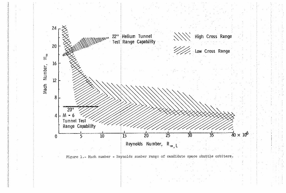
Mach number and Reynolds number. Figure 1 presents the facility capa-
bilities superimposed over the Mach number-Reynolds number ~nvelopes
generated by various shuttle candidates flying the proposed entry tra-
jectories for both high and low cross range (see, for example, refs. 4-6).
At M ~ 17 + 20, the 22-inch helium tunnel has the capability to duplicate
Reynolds number for all candidates. While the 20-inch tunnel does not dupli-
cate the complete range of Reynolds numbers at M = 6, it does cover enough of
the envelope to simulate expected conditions for low cross-range flight for
both the fixed straight wing and fixed delta wing configurations. The test
medium in both facilities is an ideal gas and, therefore, free-stream condi-
tions are known and test conditions repeatable; however, experience has
shown, as is the case with all ground facilities, that care must be used in
interpreting test results. Nonetheless, with careful analysis of the test
-4-
data and'treatment of the results in the proper perspective, data from
both facilities can be used to predict free-flight shuttle performance.
DISCUSSION
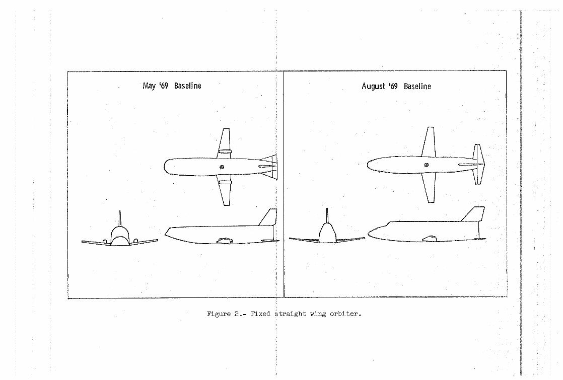
Fixed Straight Wing Orbiter.- During the initial planning stages
of the space -shuttle effort, the fixed straight wing concept was the base-
line design frozen in May 1969, shown on the left of figure 2. A very
blunt forebody and engine nacelles above the wing characterize this con-
figuration. Just prior to the initiation of hypersonic testing, the Aug-
ust 1969 baseline design revision, shown on the right of figure 2, was
completed and included in the test program.- Most of the design changes
were the result of low-speed tests conducted during the interim between
(ref. 7). Some of the more apparent alterations are a rounding of the
body corners (softening the chine lines) to improve high angle-of-attack
handling qualities and reduce buffet due to unsymmetrical vortex shedding,
a reduction of nose bluntness to move the center of pressure aft and in-
creased horizontal tail and control area to provide more longitudinal -,
stability and trim control. While configurationcE:nter-of-gravity location
is still subject to packaging studies, a range of from 0.525 L to 0.543 L
is being considered. The results being presented are based on a center of
gravity located at 0.535 L (0.25 MAC).
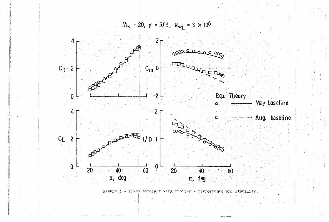
Experimental results obtained at Moo = 20, ~ L ~ 3 x 10⁶ on both de-, signs are compared with Newtonian impact theory (Cp,max = 2) in figure 3.
In general, the May baseline configuration had undesirable stability char-
acteristics and did not trim in the test angle-of-attack range. The August
-5-
design revision for improving subsonic characteristics also greatly im-
proved the hypersonic stability and trim characteristics. The revised
design trimmed at a ~ 35 0 with 0 = 0 0, developed a CL,max Z 2.3 at
a ~ 50 0, and had an LID ~ 1.55 at a = 20 0
• Experimental results for
both vehicles agreed quite well with Newtonian theory up to an a ~ 40 0
where both designs experienced an anomalous behavior in pitch. Further
comment on the agreement between experiment and theory will be made later.
The anomaly in the pitching moment is of concern, since it could influ-
ence the vehicle's ability to achieve the hypersonic design trim point of 60 0,
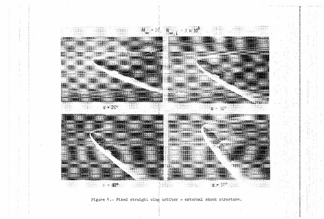
and could be indicative of a flow interference problem area. Flow visual-
ization studies using the electron beam technique (ref. 8) were conducted
in the helium tunnel in an attempt to identify the cause of the pitch
anomaly. Some selected photographs from these studies are shown in fig-
ure 4. A distinct bulge in the bow shock is evident forward of the hori-
zontal tail at a = 40 0 which becomes more prominent with increasing angle
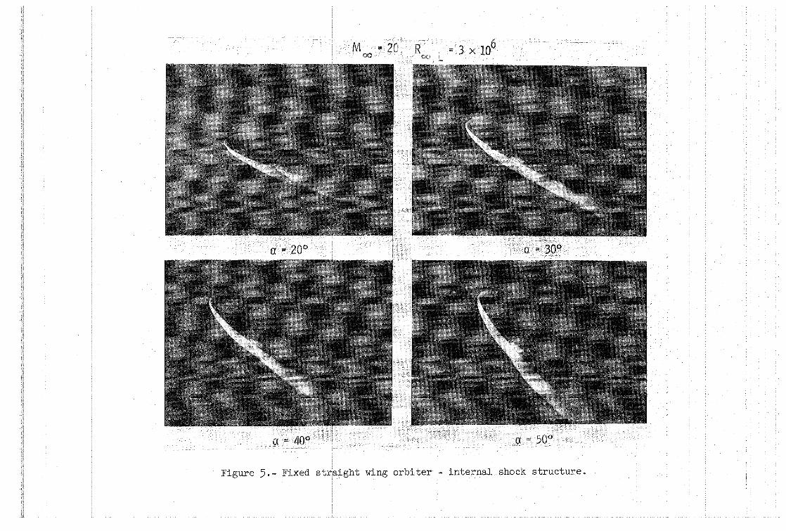
of attack. Figure 5 shows the result of applying photographic printing
techniques to the photographs in figure 4 to bring out the flow details
interior to be bow shock. These prints indicate that the protrusion in
the bow shock is due to a bow shock-wing shock intersection. Hypersonic
studies conducted on simple flared bodies of revolution (ref. 9) showed
expansions originating from body shock-flare shock interactions reduced
flare pressures causing pitchup. Although not visible in figure 5, it is
speculated that a similar phenomenon occurs on this complex shape, that is,
expansions generated by the intersection of bow and wing shocks and reflec-
ted back into the flow field impinge upon the horizontal tail and generate
the anomalus behavior shown in figure 3.
-6-
Additional views of the vehicle were taken to clarify the shock
interaction pattern. Three of these views - bottom plan, front top,
and top rear- are shown in figure 6. These views were obtained at
a = 40° to show the interference pattern at the initiation of pitchup.
Of particular interest~a1:"~_ the shock\intersections crossing beneath the
fuselage forward of the empennage, and the body shock crossing the wing
inboard of the wing tips. Stability and heating problems have been shown
to result from these types of interactions. But it should be pointed out
that complex flowfields of this type are extremely sensitive to model
attitude and free-stream conditions. In the low cross-range attitude
(a "" 60°), the vehicle I s flow pattern differs considerably from that shown
in the figure. In addition, flow patterns at full-scale--free-flight con-
point is that, while ground facility data pinpoint possible problem areas,
the extrapolation of tunnel data to free-flight--full-scale conditions for
configurations generating complex flow fields is not as well understood
as similar extrapolations for configurations with simple flow fields.
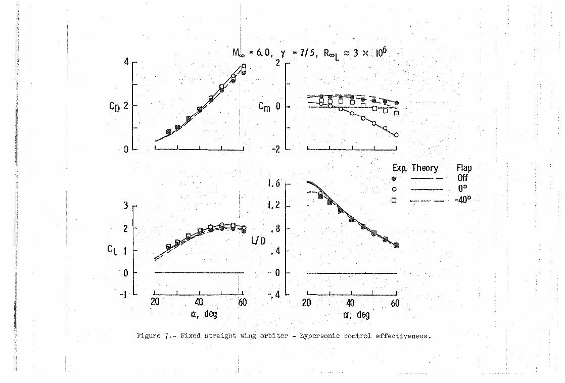
The results of control effectiveness studies conducted on the August
baseline design at ~ = 6 are presented in figure 7. These data indicate
the vehicle has the capability to trim to the high attitudes required for
low cross-range operation, even though the aerodynamic trim control
(elevator) was not as effective as impact theory predicted. The anomaly
in pitching moment noted at Mb = 20, a = 40° was not apparent during
these tests; but as mentioned earlier, these complex interference flows
are very sensitive to model attitude and free-stream conditions. General
-7-
performance levels (CL versus a, CD versus a, and LID vs a) for <5 = 0°
were not only predicted by impact theory but were essentially identical
to the Moo = 20 helium test results.
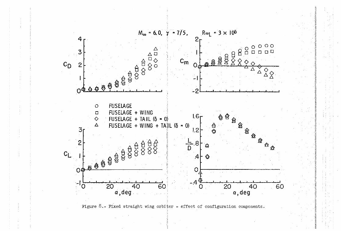
The results of configuration component buildup studies at Moo = 6
are shown on figure 8. As was expected, the fuselage was unstabte, but
the horizontal tail provided the required stabilizing influence. The
most unexpected result was the independence of LID from configuration com
position at angles of attack above 20°. Past studies on high-performance
configurations had shown fuselage fineness ratio and volume distribution
to be the big performance drivers for entry vehicles. But these previous
studies were on shapes with only minor protuberances, if any. For this
fixed straight wing orbiter, the unswept wing and tail might have been
expected to reduce performance, particularly near a = 20°, by contri
buting large drag increments. However, these surfaces increased lift and
drag by the same factor such that the fuselage performance potential was
unaffected by the addition of these large areas.
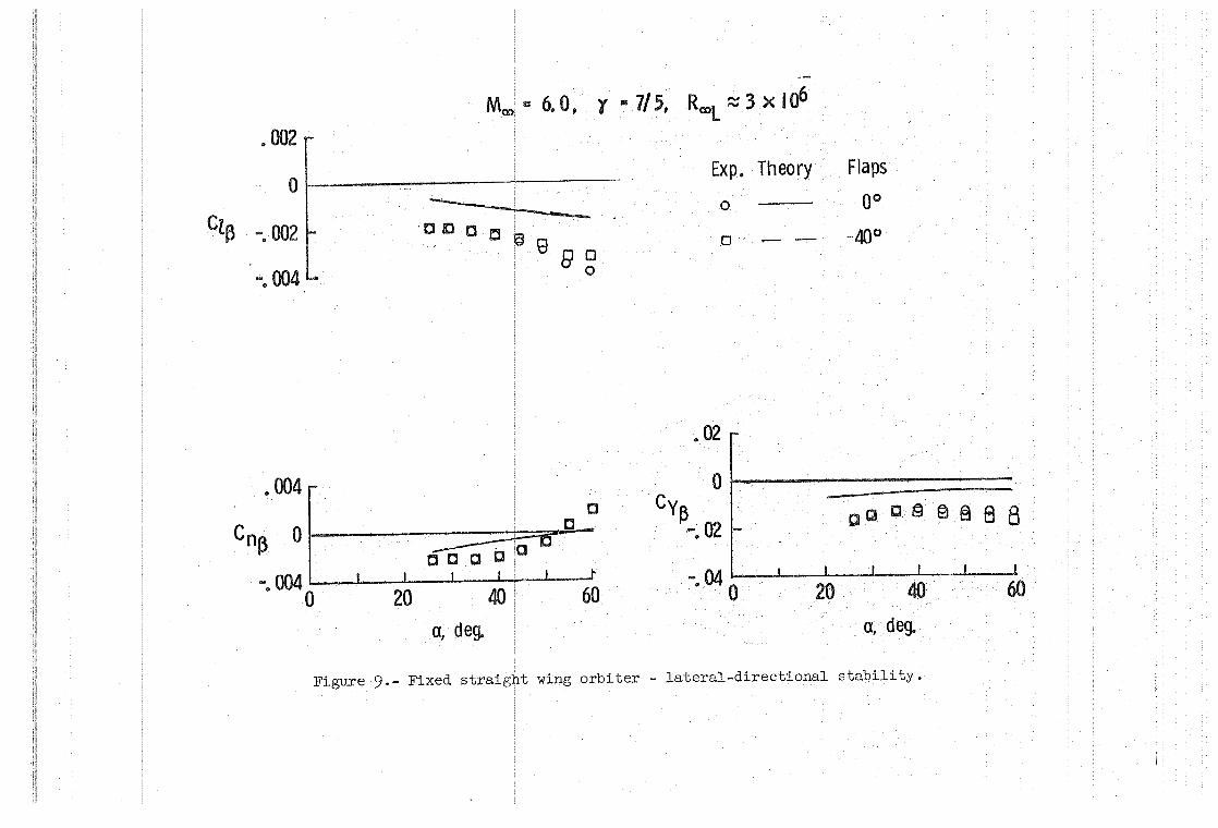
Lateral-directional stability studies (M = 6, fig. 9) showed the
vehicle to be statically stable at the design angle of attack (a = 60°).
Static directional instability was indicated at angles of attack less
than 55°, but analytical studies indicate that the magnitude of the effec
tive dihedral and vehicle inertias are sufficient to maintain dynamic
stability at angles of attack as low as 40°. Newtonian theory does not
predict the lateral-directional characteristics.
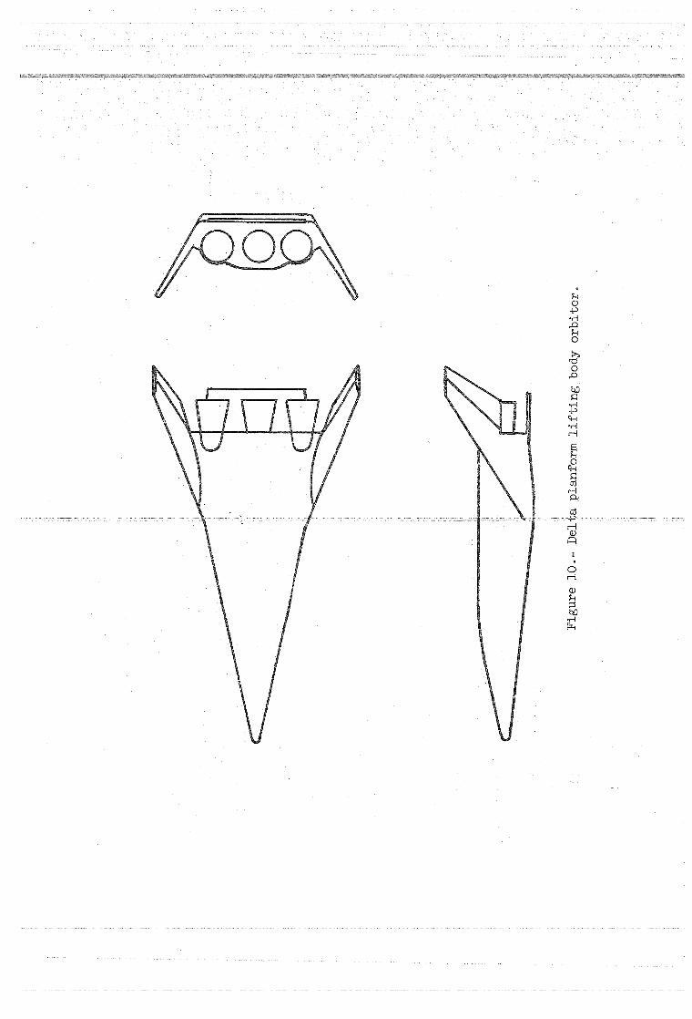
Delta Plan form Lifting Body Orbiter.- Basically, the lifting body
studied has a double delta planform having tip fins rolled out 30° and
toed in 5° for lateral-directional stability, and base elevons for
-8-
longitudinal stability and trim control (figure 10). Configuration
center of gravity, based on vehicle packaging and realistic weight
and balancestudies" is at 72% of the fuselage length referenced to the
virtual origin of the planform.
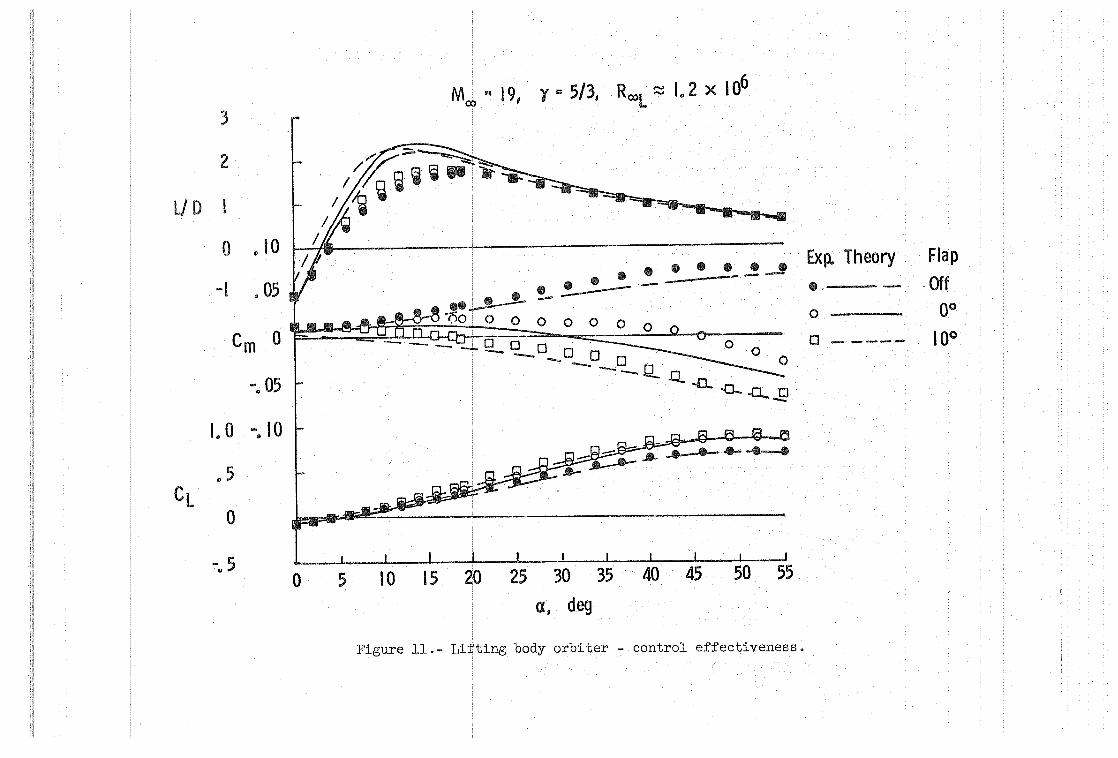
Control effectiveness tests conducted at Moo = 19, Roo,L .~ 1.2 x 10⁶
in helium (figure 11) indicated the delta planfbrm lifting body orbiter
had a trim capability of at least from CL,max' (a~ 55°, CL ~ .8, L/n ~ .6)
to L/Dmax (a :::: 18°, CL ~ .35, L/D '" 1.8) for the 72% center-
of-gravity location. While this trim capability does satisfy one of the
design goals for this particular candidate (both high and low cross-range
capability) it cou~d also introduce some difficulity. From the ILRV
studies this vehicle was sized to have an overall length of approximately
160 feet with~!~!<>'I1:~_£-? __ ~E':~t long ..... For control~1!!Jacesthis la.r.8-e~,~j;;.his~ .. _. _~_ ... __ . __ . __ . __
system may be overly sensitive (2.8 degrees trim per degree control deflec-
tion) and in the presence of structural deflections due to the high
heating, high loading conditions of entry, it could become difficult to
accurately control trim angle of attack with this degree of control
sensitivity.
Newtonian impact theory (Cp ,max = 2) adequately predicted performance
for 25°<a<55°). Prediction of (L/D)max was considerably high which is to be
expected since no approximations to account for viscous effects were added
to the theory. Trim angle 'of attack was underpredicted consistently by 15°.,
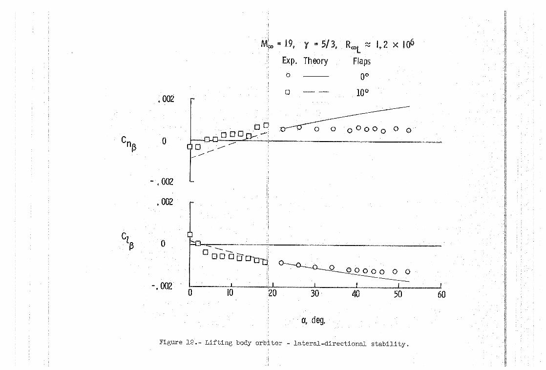
The results of lateral-directional stability tests(fig. 12) indicate
no apparent static instabilities for the lifting body concept throughout
the design operational angle-of-attack range (18° <a<55°). Newtonian
-9-
theory overpredicted stability for high angles of attack (8 = 0°,
ex> 30°). Correlation between theory and experiment was not expected,
but past experience on high performance vehicles had shown a general
trend of underprediction of lateral direction characteristics, as seen
in figure 12 at the lower angles of attack (8 = 10°). Therefore, the
degree of overprediction shown here was not expected.
Flow visualization studies on this configuration revealed a fairly
typical lifting body flow field characterized at ex > 20° by a strong·
detached shqck wave with no apparent internal flow field shocks.
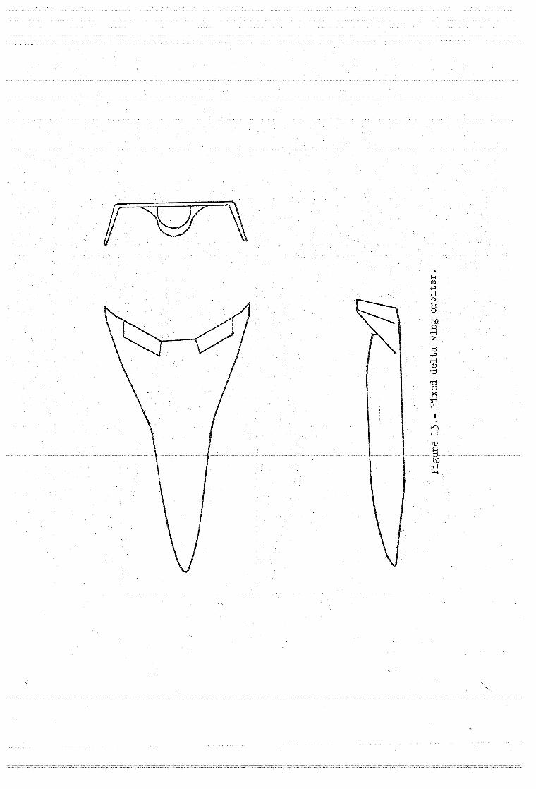
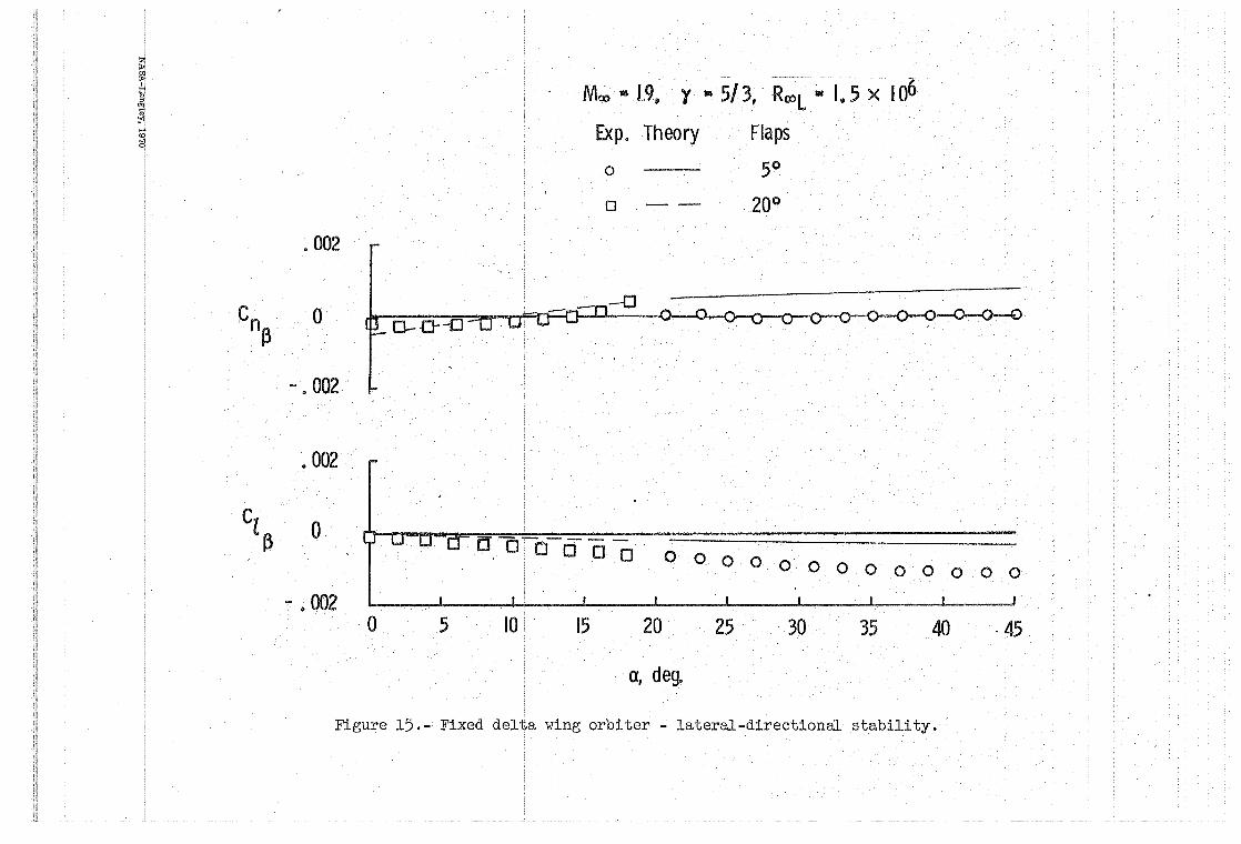
Fixed Delta Wing Orbiter.- Figure 13 presents a three-view sketch
of fixed delta wing orbiter being studied. Longitudinal stability is
provided by the delta wing having swept leading and trailing edges. Wing
. tip fins toed in 5° and rolled out 13.5° furnish lateral-directional sta
bility and trailing edge elevons provide trim and roll control. Stability
data are referenced to a center of gravity located at 66% of the fuselage
length (nose to base).
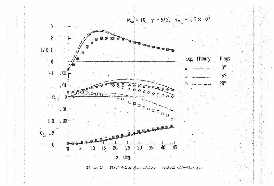
Hypersonic control effectiveness tests (figure 14) indicate this
\ configuration, like the lifting body orbiter, can be trimmed from
{L!D)max (ex "" 19°, 8 = 20°) to the design entry angle of attack (ex "" 45°,
8 = 5°). Preliminary heating analysis indicates the 20° flap defle.ction
required for trim at {L!D)max could cause excessive wing and flap heating
for high cross-range operation. The design high cross-range entry tra-
j ectory and accompanying heating conditions were based on pitch modulation
of a vehicle with a theoretical (L!D)max of not less than 2.4. As shown
on the figure, M= 19 tests indicate a maximum L!D capability of 2. To
meet the l500n.m .. high cross-range requirement using the present mode of
-10-
operation,either the vehicle would need redesign to increase LID or
the entry trajectory would have to be modified.
The comments made about the theoretical predictions of lifting
body performance apply here except trim angle of attack was overpre
dieted by as much as 8°. The fickle nature of trim predictions by
impact theory is exemplified when these results are compared with the
lifting body results where trim was underpredicted by 15°.
Directional and lateral stability characteristies are presented
in figure 15 for the control deflections required for trim at both the
low and high cross-range attitudes. The vehicle possessed lateral sta
bility over the .test angle-of-attack range, but above a = 20° neutral
stability is experienced. This is no real problem since, in the verna-
cularof . con t rol~s_y_,$_t_ems~t_e_chnQJ,Gffibj,==U---=£-aa..be.~4a~k--.b~~~~utcc..r-e.!l~· .~. ~ .. --.--_ .. ~--.--.-
control tests show this configuration develops adverse yaw due to roll
control. While directional stability and yaw due to roll control are two
separate and distinct parameters, these quantities are tied together in
consideration of vehicle dynamics and handling qualities. Inherent direc-
tional stability, when· it exists, tends to counteract adverse yaw due to
roll control. High angle-of-attack neutral static directional stability,
however, in the presence of this adverse control effect,could lead to con-
trol and handling problems during entry.
Flow visualization studies on the fixed delta wing concept revealed
some interesting interference effects at angles of attack near zero.
This area was not pursued further since it is of no consequence for space
shuttle operation. At the attitudes of interest (a ~ 20°) a two-shock
-11-
system appears to exist but these shocks merge without any interference
effects being generated.
CONCLUDING REMARKS
These results, obtained prior to the Phase B space shuttle effort,
indicate each of the three shuttle concepts satisfies its performance
goals for center-of-gravity positions based on realistic packaging studies,
but both force data and flow visualization studies indicate there are
possible problem areas and expose a need for more detailed studies. In
fact, extensive ground facility testing of all types (force, pressure,
heating, flow visualization, etc.) will be required throughout the Phase B
activity. With this future effort in mind, there are two points which
should be made very clear. First, throughout the presentation, reference
has been made to whether or not Newtonian theory predicted longitudinal
trim and lateral-directional stability. The force and momen~ data pre
sented on these three different configuration types graphically illustrate
the inadequacy of impact theory for predicting trim, stability, and design
ing aerodynamic controls for hypersonic entry. This conclusion is not new
nor startling, but space shuttle designers are relying on impact theory,
which does an adequate job of predicting vehicle performance over most of
the operational angle-of-attack range, to design these vehicles. No theory,
simple or complex, will provide an adequate knowledge, a priori, of the
static stability and control of the diverse space shuttle candidate config
urations. All design judgments concerning hypersonic aerodynamic control,
as well as all static stability and control derivatives for determining
hypersonic dynamic stability and handling qualities, must be based on
-12-
ground facility data. Second, tunnel data does not simply stand alone.
For instance, as flow field complexity increases, aerodynamic charac
teristics become more sensitive to conditions which cannot be simulated
on scale models in ground facilities. Results must therefore be care
fully analyzed and treated in the proper perspective to reliably predict
free-flight, full-scale vehicle behavior.
-13-
REFERENCES
1. Arrington, James P.; Ashby, George C., Jr.: Hypersonic Aerodynamic Characteristics Associated with the Evolution of a Maximum LiftDrag Ratio 3 Entry Configuration. NASA Proposed TM, L-72ll.
2. Lloyd, J. T.: Preliminary Design and Experimental Investigation of the FDL-5A Unmanned High LID Spacecraft. AFFDL-TR-68-24, March, 1968.
3. Faget, Max: Space Shuttle: A New Configuration. Astronautics and Aeronautics, pp. 52-61, January 1970.
4. Final Study of Integral Launch and Reentry Vehicle System, Final Report. Space Division, North American Rockwell, SD 69-573-3, MSC 00192, December 1969.
5. Final Report - Integral Launch and Reentry Vehicle. LMSC Space Systems Division. LMSC-A959837, December 22, 1969.
6. A Two-Stage Fully Reusable Space Transportation System Phase A Final Report. Martin-Marietta Corporation, Denver Division, MSR-69-36, December 1969.
7. Decker, John P. and Spencer, Bernard, Jr.: Low-Subsonic Aerodynamic Characteristics of a Model ofa Fixed-Wing Space Shuttle Concept at Angles of Attack to 76 0
• NASA TN X-1996, April 1970.
8. Weinstein, Leonard M; Wagner, Richard D., Jr.; Henderson, Arthur, Jr.; and Ochettree, Stewart R.: Electron Beam Flow Visualization in Hypersonic Helium Flow. Presented at the 1969 IEEE Third International Congress on Instrumentation in Aerospace Simulation Facilities, Farmingdale, New York, May 5-8, 1969.
9. Fitzgerald, Paul E., Jr.: The Effect of the Bow-Shock-Flare-Shock Interaction on the Static Longitudinal Stability of Flare-Stabilized Bodies. at Hypersonic Speeds. NASA TM X-664, 1962.

24 I "\/'_ . r~'\\" 22" Helium Tunnel ~ ~ High Cross Range
20 I-~ . Test Range Capability
~ L .,-,,'\.'\,l,A. ~ ~ ~ Low Cross Range
, 16 !.... CJ.) ...c E ::::l Z 12 .c u ru :2:
8
4
,//////////~~ o 5 10 115 2'0 25 3b 3~ lo x 106
Reynolds Number, Roo L ,
Figure 1.- Mach number - Reynolds number range of candidate space shuttle orbiters.
May D69 Baseline August D69 Baseline
s s
~C ~ 1-A- --~---: ~ I
Figure 2.- Fixed ~traight wing orbiter.
4
Co 2
o
4.
Cl 2
o
Moo :3 20, Y :3 5/3, RooL ,. 3 x 10⁶
2
em 0
-2
2
~~
~'I4!...o 0 c::tl!fJ ............... ,
Exp. Theory o May bas eli ne
o - - - Aug. bas eli ne
LID I
20 40 J
60 0 1 I I
20 40 60 a, deg 0, deg
Figure 3.- Fixed straight wing orbiter - performance and stability.
a
Figure 4.- Fixed straight orbiter - external shock structure.
00
a
a a '"
Figure 5.- Fixed straight wing orbiter - internal shock structure.
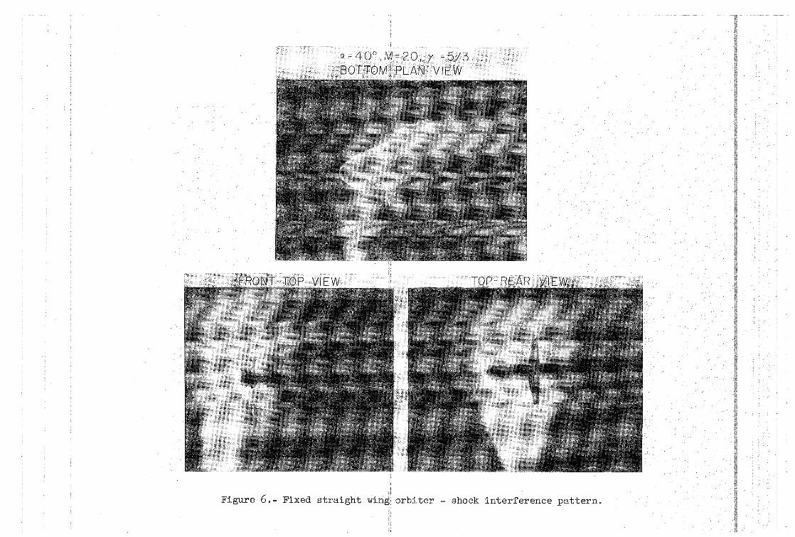
Figure 6.- Fixed straight
=20,y=5/3 PLAN VIEW
orbiter - shock interference pattern.
4
Co 2
o
3
2
CL I
o ...
-I
Moo :8: 6. 0, y lIS 1/5, Rool ~ 3 x , 106 2
/~
/
20 40 60 a, deg
Cm 0
-2
I. 6 '
. I. 2
LID . 8
.4
., 0
-.4 20 40
a, deg
Exll Theory • o o
60
Figure 7.- Fixed straight wing orbiter - hypersonic control effectiveness.
Flap Off 0°
-40°
Moo '" 6. 0, Y '" 7/5, Rool .. 3 x 100
2
f:::. o 0 000
f:::.D 8800000
f:::.°O em 0 j~g 0 Co 2~ e 08 0
f:::.vo . ~8S -I
f:::.f:::.g
e$~~ -2 OQ! e V y! . ! • I, • ,
0 FUSELAGE o FUSELAGE + WING·. . o FUSELAGE + TAil (0 • ~ 1.6[ ~ ~ &I
3 A FUSELAGE + WING + TA'IL (6 • 0) f) S r [1.2 () ~
~ 2~ . L\flL\L\ ..!:.-.st St o £l 0 0 0.0 ~
CL I ~ . ~ ~ B 8 8 88 .4 ~ ~~~
~t : ,I",,, "4 - 0 20 40 601 -. o. 20 40 60
a,deg a,deg
Figure 8. - Fixed straight wing orbi;ter - effect of configuration components.
Moo • 6.0, '1 '" 1/5, Rool :;::: 3 x 10⁶
.002 I
0\ Exp. Theory Flaps
0° ----- 0
Cl~ -.002 ~ em --o to 0 0 e 0 - - -40°
~3 9 0
-.004 I 0
.. 02
.004 I 0
0_ CnP. °l-~fj
I'" 0 0 C .t I I I
-. 004 6 20 40 60
01 L -----:===:=~~ Cy~_ 02 1_
o
-.040
CO c a @I ~ 8 B
2(} 40
a, deg. a, deg.
Fj.gure 9. - Fixed straight ,\ling orbiter - lateral-directional stability.
3
2
UD
0 " 10
-I .05
Cm 0
-005
I.. 0 -. 10
,,5 CL
0
- 5 '0
0
Moo .. 19, r" 5/3, RooL ~ I.. 2 x 10⁶
•••••• e e Ex T -t'.J.---!- _ :=---- - - - ..! J Po heory
,0 0 __ --QJ--n--o ° 0 0 e·---_ 0 0
---'Lo ~' .0.0 _0 0 -_ 0 .0 0 --Q..Q ° 0 - ----
..Q..-o- ..0.... '0 -
l_~l __ -L.._---I __ -'-____ J..-_--J
5 10' 15 20 25 30 35 40 45 50 55
0, deg
Figure 11.- Lifting body orbiter - control effectiveness.
Flap
Off 00
100
.002
Cn 0 ~
Cz ~
- .002
.002
o
-.002' 0
o
--0 00000-0
10
n 19, Y 25/3, RooL ~ 192 X 106
Exp. Theory Flaps 0 0°
0 -- 10°
o 0°00000
° 0
30 40 50
a, deg.
Figure 12.- Lifting body orb~ter - lateral-directional stability.
60
IV\
Ct' .. 5
o o 5 I 0 15 20 25 30 35 40 45
Cl, de90
Figure 14.- Fixed delta orbiter - control effectiveness.
~ ~ I
J .... <0
2l
Cn .~
Cz ~
Moo • 19 •. Y .. 5/3,· RC»L .. Cs x 100
Exp. Theory Flaps
o 5°
o -- -- 20°
.002
o rtT - -0-0 0- 0-~::n 1 I-d~ 0 ---0--0--0
".002
. 002
0 cJ"OOOODo
0000000 0 000 0 0
- .002 L _ _ _________ i ____ ..l
0 5 10 15 20 25 30 35 40 ·45
0, deg.
Figure 15.- Fixed delta wing orbiter - lateral-directional stability.