Embed Size (px)
Citation preview
PENBERTHY MAGNETIC LIQUID LEVEL GAUGESMODELS MG/MG2/MGVB/MGGR/TMMG
FEATURES
• Hermetically sealed indicator with 316 SS housing.
• Optional gold anodized flags and followers.• Standard and concentric magnet design for
superior coupling.• Custom weighted magnetic float.• Chamber designed to ASME B31.3 and B31.1.• Easy installation and virtually
maintenance-free.• Optional magnetically coupled clamp on
transmitters and switches available for the magnetic liquid level gauge.
• Model MGVB (vapor bypass) provides superior solution to process flashing.
• Model MGGR features independent guided wave radar level transmitting for true redundancy in a single package.
Emerson.com/FinalControl © 2017 Emerson. All Rights Reserved. VCTDS-00669-EN 17/10
Multiview™ products offer a superior solution to liquid level monitoring and a viable alternative to glass level gauges, float switches, displacers and other mechanical and electronic level technologies
GENERAL APPLICATION
The Multiview™ product line offers an extensive range of models and accessories to meet the needs of both simple and stringent level measurement applications in petrochemical processing, refining, compressors, water treatment, storage tanks and oil water separators.
TECHNICAL DATA
Materials: 304/304L SS, 316/316L SS, Alloy 20Cb3, Hastelloy® C276, Monel®, PVC, CPVC, PVDF, Tefzel® lined, Halar® lined
PressuresFloats: Up to ASME Class 900 Standpipes: Up to 3100 psig
(213.8 barg)
Minimumspecific gravity: 0.37
Temperature range: -325°F to 750°F (-198°C to 400°C)
2
PENBERTHY MAGNETIC LIQUID LEVEL GAUGESMULTIVIEW INDICATORS
MULTIVIEW™ FOLLOWER-TYPE AND FLAG-TYPE INDICATORS
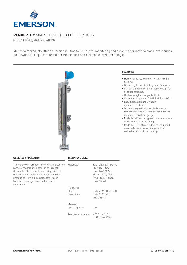
FOLLOWER-TYPE INDICATION
These units consist of a hermetically sealed tube in a protective view housing. Within this tube is a gold (other colors are available) anodized aluminum follower which will mirror level changes in the process tank. This entire assembly is attached to the standpipe, where the follower is coupled magnetically with the float.
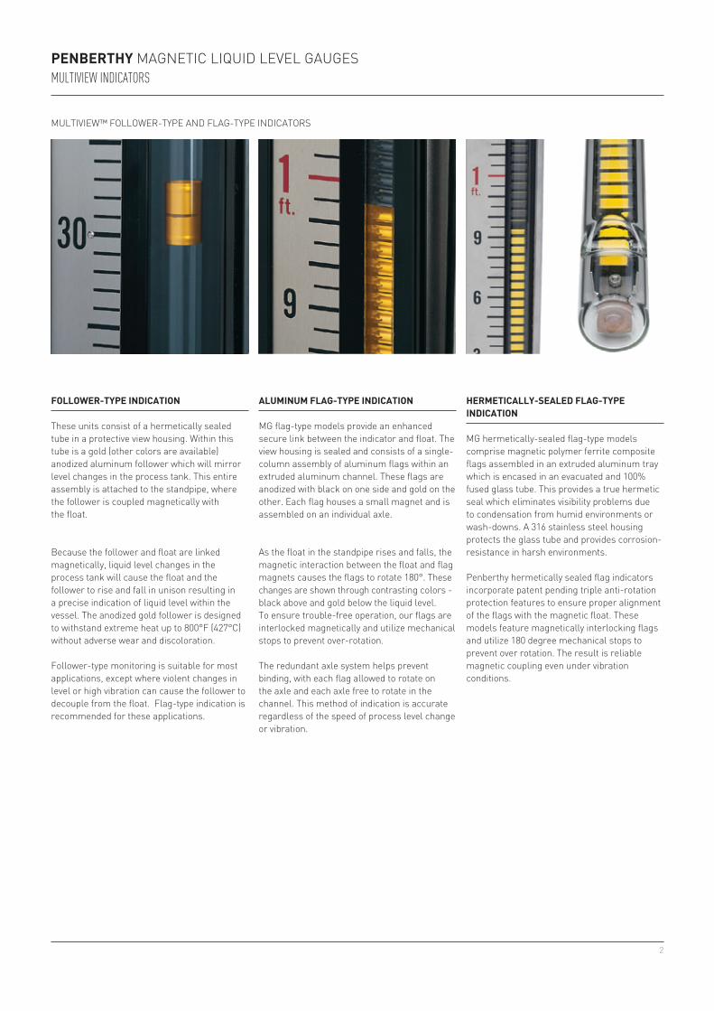
ALUMINUM FLAG-TYPE INDICATION
MG flag-type models provide an enhanced secure link between the indicator and float. The view housing is sealed and consists of a single-column assembly of aluminum flags within an extruded aluminum channel. These flags are anodized with black on one side and gold on the other. Each flag houses a small magnet and is assembled on an individual axle.
Because the follower and float are linked magnetically, liquid level changes in the process tank will cause the float and the follower to rise and fall in unison resulting in a precise indication of liquid level within the vessel. The anodized gold follower is designed to withstand extreme heat up to 800°F (427°C) without adverse wear and discoloration.
Follower-type monitoring is suitable for most applications, except where violent changes in level or high vibration can cause the follower to decouple from the float. Flag-type indication is recommended for these applications.
As the float in the standpipe rises and falls, the magnetic interaction between the float and flag magnets causes the flags to rotate 180°. These changes are shown through contrasting colors - black above and gold below the liquid level. To ensure trouble-free operation, our flags are interlocked magnetically and utilize mechanical stops to prevent over-rotation.
The redundant axle system helps prevent binding, with each flag allowed to rotate on the axle and each axle free to rotate in the channel. This method of indication is accurate regardless of the speed of process level change or vibration.
HERMETICALLY-SEALED FLAG-TYPE INDICATION
MG hermetically-sealed flag-type models comprise magnetic polymer ferrite composite flags assembled in an extruded aluminum tray which is encased in an evacuated and 100% fused glass tube. This provides a true hermetic seal which eliminates visibility problems due to condensation from humid environments or wash-downs. A 316 stainless steel housing protects the glass tube and provides corrosion-resistance in harsh environments.
Penberthy hermetically sealed flag indicators incorporate patent pending triple anti-rotation protection features to ensure proper alignment of the flags with the magnetic float. These models feature magnetically interlocking flags and utilize 180 degree mechanical stops to prevent over rotation. The result is reliable magnetic coupling even under vibration conditions.
3
1
2
3
4
5
6
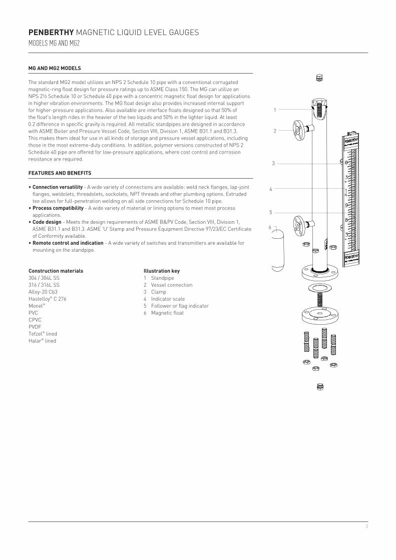
Illustration key1 Standpipe2 Vessel connection3 Clamp4 Indicator scale5 Follower or flag indicator6 Magnetic float
MG AND MG2 MODELS
The standard MG2 model utilizes an NPS 2 Schedule 10 pipe with a conventional corrugated magnetic-ring float design for pressure ratings up to ASME Class 150. The MG can utilize an NPS 2½ Schedule 10 or Schedule 40 pipe with a concentric magnetic float design for applications in higher vibration environments. The MG float design also provides increased internal support for higher-pressure applications. Also available are interface floats designed so that 50% of the float's length rides in the heavier of the two liquids and 50% in the lighter liquid. At least 0.2 difference in specific gravity is required. All metallic standpipes are designed in accordance with ASME Boiler and Pressure Vessel Code, Section VIII, Division 1, ASME B31.1 and B31.3. This makes them ideal for use in all kinds of storage and pressure vessel applications, including those in the most extreme-duty conditions. In addition, polymer versions constructed of NPS 2 Schedule 40 pipe are offered for low-pressure applications, where cost control and corrosion resistance are required.
PENBERTHY MAGNETIC LIQUID LEVEL GAUGESMODELS MG AND MG2
FEATURES AND BENEFITS
• Connection versatility - A wide variety of connections are available: weld neck flanges, lap-joint flanges, weldolets, threadolets, sockolets, NPT threads and other plumbing options. Extruded tee allows for full-penetration welding on all side connections for Schedule 10 pipe.
• Process compatibility - A wide variety of material or lining options to meet most process applications.
• Code design - Meets the design requirements of ASME B&PV Code, Section VIII, Division 1, ASME B31.1 and B31.3. ASME 'U' Stamp and Pressure Equipment Directive 97/23/EC Certificate of Conformity available.
• Remote control and indication - A wide variety of switches and transmitters are available for mounting on the standpipe.
Construction materials304 / 304L SS316 / 316L SSAlloy-20 Cb3Hastelloy® C 276Monel®
PVCCPVCPVDFTefzel® linedHalar® lined
4
PENBERTHY MAGNETIC LIQUID LEVEL GAUGESMODELS MG AND MG2
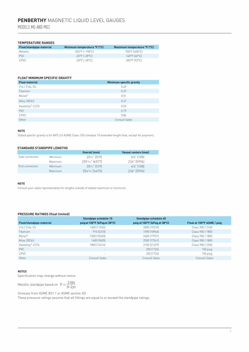
FLOAT MINIMUM SPECIFIC GRAVITYFloat material Minimum specific gravity316 / 316L SS 0.49Titanium 0.37Monel® 0.51
Alloy-20Cb3 0.47
Hastelloy®-C276 0.53PVC 0.79CPVC 0.86Other Consult Sales
STANDARD STANDPIPE LENGTHSOverall (mm) Vessel centers (mm)
Side connection Minimum 20 7⁄16" (519) 4¼" (108)Maximum 259 15⁄16" (6577) 236" (5994)
End connection Minimum 20 7⁄16" (519) 4¼" (108)Maximum 254 15⁄16"(6475) 236" (5994)
TEMPERATURE RANGESFloat/standpipe material Minimum temperature °F (°C) Maximum temperature °F (°C)Metallic -325°F (-198°C) 750°F (400°C)PVC -20°F (-28°C) 140°F (60°C)CPVC -20°F (-28°C) 200°F (93°C)
PRESSURE RATINGS (float limited)
Float/standpipe materialStandpipe schedule 10 Standpipe schedule 40
Float at 100°F ASME / psigpsig at 100°F (kPag at 38°C) psig at 100°F (kPag at 38°C)316 / 316L SS 1600 (11034) 2800 (19310) Class 900 / 2160Titanium 915 (6310) 1590 (10966) Class 900 / 1800Monel® 1500 (10345) 2600 (17931) Class 900 / 1800Alloy-20Cb3 1400 (9655) 2500 (17241) Class 900 / 1800Hastelloy®-C276 1800 (12414) 3100 (21379) Class 900 / 2250PVC - 250 (1724) 150 psigCPVC - 250 (1724) 150 psigOther Consult Sales Consult Sales Consult Sales
NOTEConsult your sales representative for lengths outside of stated maximum or minimum.
NOTESSpecification may change without notice.
Metallic standpipe based on
Stresses from ASME B31.1 or ASME section IID.These pressure ratings assume that all fittings are equal to or exceed the standpipe ratings.
NOTEStated specific gravity is for NPS 2½ ASME Class 150 schedule 10 extended length float, except for polymers.
5
1
4
3
5
2
7
6
PENBERTHY MAGNETIC LIQUID LEVEL GAUGESMODEL MGVB
MGVB (VAPOR BYPASS) MODEL
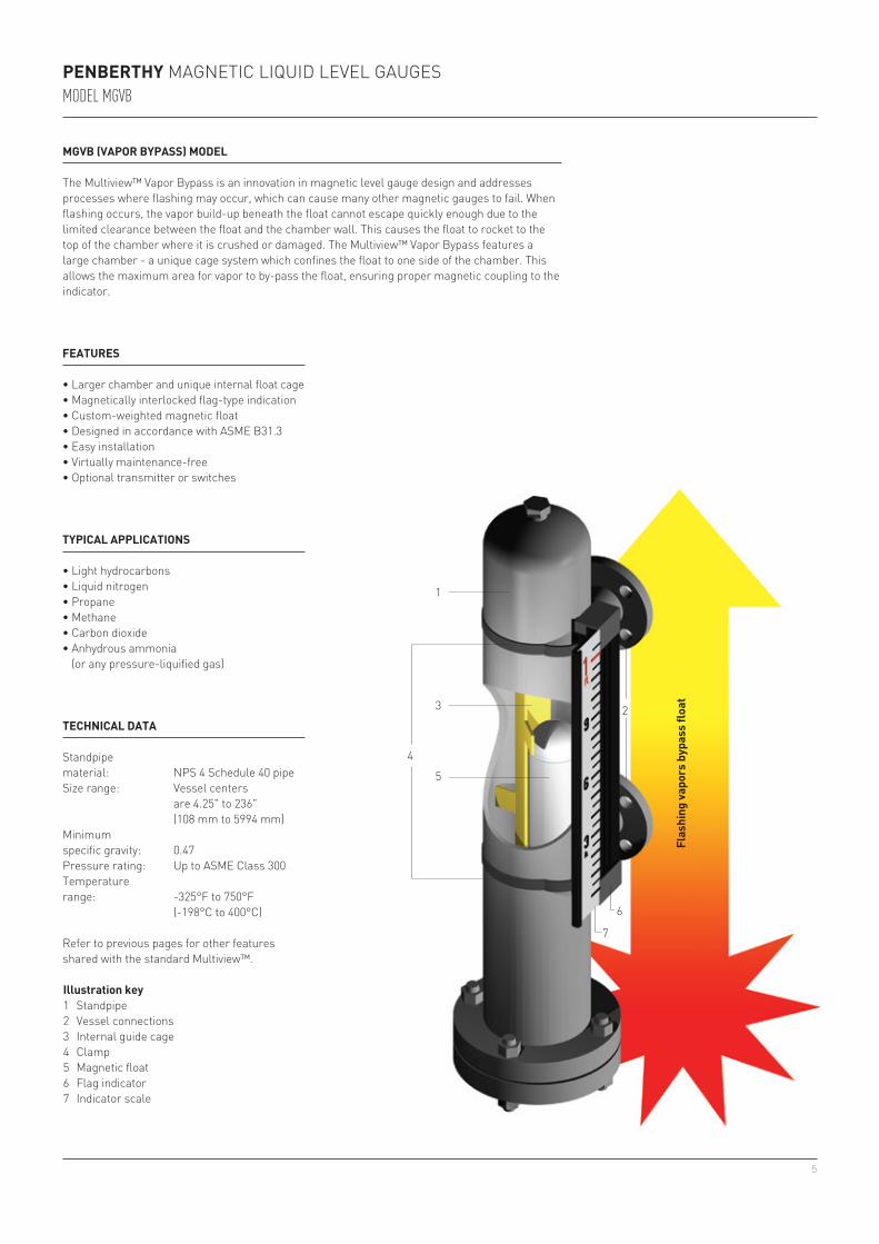
The Multiview™ Vapor Bypass is an innovation in magnetic level gauge design and addresses processes where flashing may occur, which can cause many other magnetic gauges to fail. When flashing occurs, the vapor build-up beneath the float cannot escape quickly enough due to the limited clearance between the float and the chamber wall. This causes the float to rocket to the top of the chamber where it is crushed or damaged. The Multiview™ Vapor Bypass features a large chamber - a unique cage system which confines the float to one side of the chamber. This allows the maximum area for vapor to by-pass the float, ensuring proper magnetic coupling to the indicator.
Illustration key1 Standpipe2 Vessel connections3 Internal guide cage4 Clamp5 Magnetic float6 Flag indicator7 Indicator scale
FEATURES
• Larger chamber and unique internal float cage• Magnetically interlocked flag-type indication• Custom-weighted magnetic float• Designed in accordance with ASME B31.3• Easy installation• Virtually maintenance-free• Optional transmitter or switches
TYPICAL APPLICATIONS
• Light hydrocarbons• Liquid nitrogen• Propane• Methane• Carbon dioxide• Anhydrous ammonia
(or any pressure-liquified gas)Fl
ashi
ng va
pors
byp
ass
float
TECHNICAL DATA
Standpipematerial: NPS 4 Schedule 40 pipeSize range: Vessel centers
are 4.25" to 236" (108 mm to 5994 mm)
Minimumspecific gravity: 0.47Pressure rating: Up to ASME Class 300Temperaturerange: -325°F to 750°F
(-198°C to 400°C)
Refer to previous pages for other features shared with the standard Multiview™.
6
3.5 (89) 0.504.5 (114) 0.326 (152) 0.218 (203) 0.2010 (254) 0.15
3.5 (89) 44.5 (114) 66 (152) 68 (203) 810 (254) 10
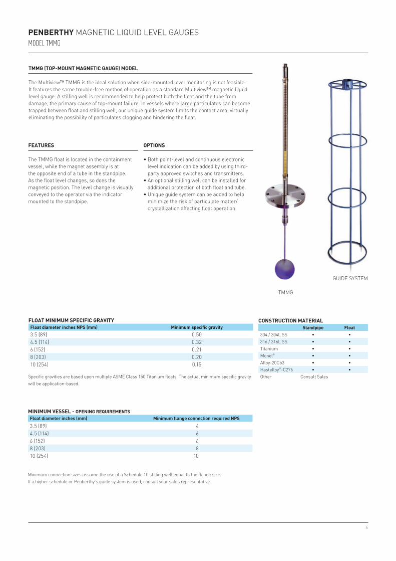
TMMG (TOP-MOUNT MAGNETIC GAUGE) MODEL
The Multiview™ TMMG is the ideal solution when side-mounted level monitoring is not feasible. It features the same trouble-free method of operation as a standard Multiview™ magnetic liquid level gauge. A stilling well is recommended to help protect both the float and the tube from damage, the primary cause of top-mount failure. In vessels where large particulates can become trapped between float and stilling well, our unique guide system limits the contact area, virtually eliminating the possibility of particulates clogging and hindering the float.
FLOAT MINIMUM SPECIFIC GRAVITYFloat diameter inches NPS (mm) Minimum specific gravity
CONSTRUCTION MATERIALStandpipe Float
304 / 304L SS • •316 / 316L SS • •Titanium • •Monel® • •Alloy-20Cb3 • •Hastelloy®-C276 • •Other Consult Sales
MINIMUM VESSEL - OPENING REQUIREMENTS Float diameter inches (mm) Minimum flange connection required NPS
TMMG
GUIDE SYSTEM
FEATURES
The TMMG float is located in the containment vessel, while the magnet assembly is at the opposite end of a tube in the standpipe. As the float level changes, so does the magnetic position. The level change is visually conveyed to the operator via the indicator mounted to the standpipe.
Specific gravities are based upon multiple ASME Class 150 Titanium floats. The actual minimum specific gravity will be application-based.
Minimum connection sizes assume the use of a Schedule 10 stilling well equal to the flange size. If a higher schedule or Penberthy’s guide system is used, consult your sales representative.
OPTIONS
• Both point-level and continuous electronic level indication can be added by using third-party approved switches and transmitters.
• An optional stilling well can be installed for additional protection of both float and tube.
• Unique guide system can be added to help minimize the risk of particulate matter/crystallization affecting float operation.
PENBERTHY MAGNETIC LIQUID LEVEL GAUGESMODEL TMMG
7
PENBERTHY MAGNETIC LIQUID LEVEL GAUGESSWITCHES AND TRANSMITTERS
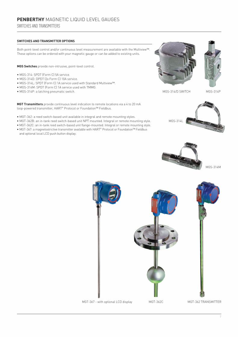
SWITCHES AND TRANSMITTER OPTIONS
Both point-level control and/or continuous level measurement are available with the Multiview™. These options can be ordered with your magnetic gauge or can be added to existing units.
MGS Switches provide non-intrusive, point-level control.
• MGS-314: SPDT (Form C) 5A service.• MGS-314D: DPDT (2x Form C) 10A service.• MGS-314L: SPDT (Form C) 1A service used with Standard Multiview™.• MGS-314M: SPDT (Form C) 1A service used with TMMG.• MGS-314P: a latching pneumatic switch.
MGT Transmitters provide continuous level indication to remote locations via a 4 to 20 mA loop-powered transmitter, HART® Protocol or Foundation™ Fieldbus.
• MGT-362: a reed switch-based unit available in integral and remote mounting styles.• MGT-362B: an in-tank reed switch-based unit NPT mounted. Integral or remote mounting style.• MGT-362C: an in-tank reed switch-based unit flange-mounted. Integral or remote mounting style.• MGT-367: a magnetostrictive transmitter available with HART® Protocol or Foundation™ Fieldbus
and optional local LCD push button display.
MGT-362 TRANSMITTER
MGS-314/D SWITCH MGS-314P
MGT-362C
MGS-314M
MGS-314L
MGT-367 - with optional LCD display
8
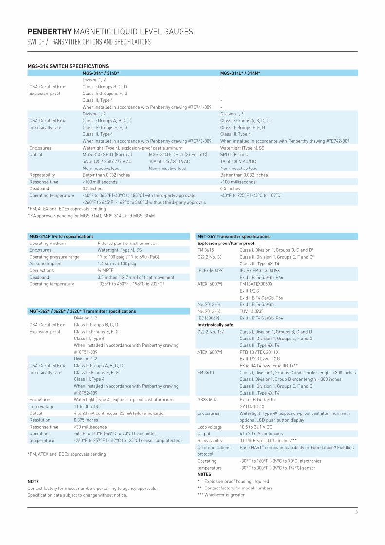
PENBERTHY MAGNETIC LIQUID LEVEL GAUGESSWITCH / TRANSMITTER OPTIONS AND SPECIFICATIONS
MGS-314 SWITCH SPECIFICATIONSMGS-314* / 314D* MGS-314L* / 314M*
CSA-Certified Ex dExplosion-proof
Division 1, 2 -Class I: Groups B, C, D -Class II: Groups E, F, G -Class III, Type 4 -When installed in accordance with Penberthy drawing #7E741-009 -
CSA-Certified Ex iaIntrinsically safe
Division 1, 2 Division 1, 2Class I: Groups A, B, C, D Class I: Groups A, B, C, DClass II: Groups E, F, G Class II: Groups E, F, GClass III, Type 4 Class III, Type 4When installed in accordance with Penberthy drawing #7E742-009 When installed in accordance with Penberthy drawing #7E742-009
Enclosures Watertight (Type 4), explosion-proof cast aluminum Watertight (Type 4), SSOutput MGS-314: SPDT (Form C)
5A at 125 / 250 / 277 V AC Non-inductive load
MGS-314D: DPDT (2x Form C)10A at 125 / 250 V AC Non-inductive load
SPDT (Form C) 1A at 130 V AC/DC Non-inductive load
Repeatability Better than 0.032 inches Better than 0.032 inchesResponse time <100 milliseconds <100 millisecondsDeadband 0.5 inches 0.5 inchesOperating temperature -40°F to 365°F (-40°C to 185°C) with third-party approvals
-260°F to 645°F (-162°C to 340°C) without third-party approvals-40°F to 225°F (-40°C to 107°C)
*FM, ATEX and IECEx approvals pendingCSA approvals pending for MGS-314D, MGS-314L and MGS-314M
MGT-362* / 362B* / 362C* Transmitter specifications
CSA-Certified Ex dExplosion-proof
Division 1, 2Class I: Groups B, C, DClass II: Groups E, F, GClass III, Type 4When installed in accordance with Penberthy drawing #18F51-009
CSA-Certified Ex iaIntrinsically safe
Division 1, 2Class I: Groups A, B, C, DClass II: Groups E, F, GClass III, Type 4When installed in accordance with Penberthy drawing #18F52-009
Enclosures Watertight (Type 4), explosion-proof cast aluminumLoop voltage 11 to 30 V DCOutput 4 to 20 mA continuous; 22 mA failure indicationResolution 0.375 inchesResponse time <30 millisecondsOperating temperature
-40°F to 160°F (-40°C to 70°C) transmitter-260°F to 257°F (-162°C to 125°C) sensor (unprotected)
MGT-367 Transmitter specificationsExplosion proof/flame proofFM 3615C22.2 No. 30
Class I, Division 1, Groups B, C and D*Class II, Division 1, Groups E, F and G*Class III, Type 4X, T4
IECEx (60079) IECEx FMG 13.0019XEx d IIB T4 Ga/Gb IP66
ATEX (60079) FM13ATEX0050XEx II 1/2 GEx d IIB T4 Ga/Gb IP66
No. 2013-54 Ex d IIB T4 Ga/GbNo. 2013-55 TUV 14.0935IEC (60069) Ex d IIB T4 Ga/Gb IP66Instrinsically safeC22.2 No. 157 Class I, Division 1, Groups B, C and D
Class II, Division 1, Groups E, F and GClass III, Type 4X, T4
ATEX (60079) PTB 10 ATEX 2011 XEx II 1/2 G bzw. II 2 GEX ia IIA T4 bzw. Ex ia IIB T4**
FM 3610 Class I, Division1, Groups C and D order length < 300 inchesClass I, Division1, Group D order length > 300 inchesClass II, Division 1, Groups E, F and GClass III, Type 4X, T4
GB3836.4 Ex ia IIB T4 Ga/GbGYJ14.1051X
Enclosures Watertight (Type 4X) explosion-proof cast aluminum with optional LCD push button display
Loop voltage 10.5 to 36.1 V DCOutput 4 to 20 mA continuousRepeatability 0.01% F.S. or 0.015 inches***Communications protocol
Base HART® command capability or Foundation™ Fieldbus
Operating temperature
-30°F to 160°F (-34°C to 70°C) electronics-30°F to 300°F (-34°C to 149°C) sensor
NOTES* Explosion proof housing required** Contact factory for model numbers*** Whichever is greater
MGS-314P Switch specificationsOperating medium Filtered plant or instrument airEnclosures Watertight (Type 4), SSOperating pressure range 17 to 100 psig (117 to 690 kPaG)Air consumption 1.4 scfm at 100 psigConnections ¼ NPTFDeadband 0.5 inches (12.7 mm) of float movementOperating temperature -325°F to 450°F (-198°C to 232°C)
NOTEContact factory for model numbers pertaining to agency approvals.Specification data subject to change without notice.
*FM, ATEX and IECEx approvals pending
9
5
1
32
5
4
1
32
5
6
4
PENBERTHY MAGNETIC LIQUID LEVEL GAUGESMODEL MGGR
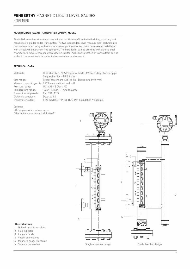
TECHNICAL DATA
Materials: Dual-chamber - NPS 2½ pipe with NPS 1½ secondary chamber pipe Single-chamber - NPS 4 pipeSize range: Vessel centers are 4.25" to 236" (108 mm to 5994 mm)Minimum specific gravity: 0.47 (based on titanium float)Pressure rating: Up to ASME Class 900Temperature range: -325°F to 750°F (-198°C to 400°C)Transmitter approvals: FM, CSA, ATEXDielectric constants: Down to 1.4Transmitter output: 4-20 mA/HART® PROFIBUS-PA® Foundation™ Fieldbus
Options:LCD display with envelope curveOther options as standard Multiview™
MGGR (GUIDED RADAR TRANSMITTER OPTION) MODEL
The MGGR combines the rugged versatility of the Multiview™ with the flexibility, accuracy and reliability of a guided radar transmitter. The two independent level measurement technologies provide true redundancy with minimum vessel penetration, and maximum ease of installation with virtually maintenance-free operation. The installation can be provided with either a dual chamber or a single chamber when space is limited. Additional switches or transmitters can be added to the same installation for instrumentation requirements.
Illustration key1 Guided radar transmitter2 Flag indicator3 Indicator scale4 Vessel connections5 Magnetic gauge standpipe6 Secondary chamber Dual-chamber designSingle-chamber design
10
PENBERTHY MAGNETIC LIQUID LEVEL GAUGESACCESSORIES
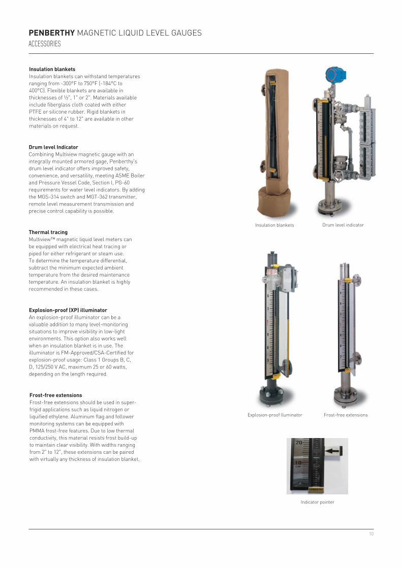
Insulation blanketsInsulation blankets can withstand temperatures ranging from -300°F to 750°F (-184°C to 400°C). Flexible blankets are available in thicknesses of ½", 1" or 2". Materials available include fiberglass cloth coated with either PTFE or silicone rubber. Rigid blankets in thicknesses of 4" to 12" are available in other materials on request.
Thermal tracing Multiview™ magnetic liquid level meters can be equipped with electrical heat tracing or piped for either refrigerant or steam use. To determine the temperature differential, subtract the minimum expected ambient temperature from the desired maintenance temperature. An insulation blanket is highly recommended in these cases.
Explosion-proof (XP) illuminatorAn explosion-proof illuminator can be a valuable addition to many level-monitoring situations to improve visibility in low-light environments. This option also works well when an insulation blanket is in use. The illuminator is FM-Approved/CSA-Certified for explosion-proof usage: Class 1 Groups B, C, D, 125/250 V AC, maximum 25 or 60 watts, depending on the length required.
Frost-free extensions Frost-free extensions should be used in super-frigid applications such as liquid nitrogen or liquified ethylene. Aluminum flag and follower monitoring systems can be equipped with PMMA frost-free features. Due to low thermal conductivity, this material resists frost build-up to maintain clear visibility. With widths ranging from 2" to 12", these extensions can be paired with virtually any thickness of insulation blanket.
Insulation blankets
Frost-free extensionsExplosion-proof lluminator
Indicator pointer
Drum level IndicatorCombining Multiview magnetic gauge with an integrally mounted armored gage, Penberthy's drum level indicator offers improved safety, convenience, and versatility, meeting ASME Boiler and Pressure Vessel Code, Section I, PG-60 requirements for water level indicators. By adding the MGS-314 switch and MGT-362 transmitter, remote level measurement transmission and precise control capability is possible.
Drum level indicator
11
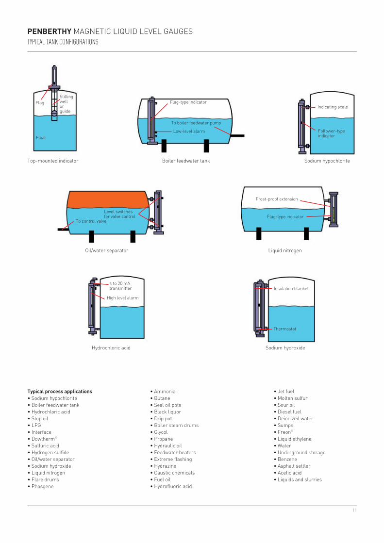
PENBERTHY MAGNETIC LIQUID LEVEL GAUGESTYPICAL TANK CONFIGURATIONS
FlagStillingwell orguide
Float
4 to 20 mA transmitter
High level alarm
Frost-proof extension
Flag-type indicator
Insulation blanket
Thermostat
Flag-type indicator
To boiler feedwater pump
Low-level alarm Follower-type indicator
Indicating scale
To control valve
Level switches for valve control
Top-mounted indicator
Liquid nitrogen
Sodium hydroxide
Boiler feedwater tank Sodium hypochlorite
Oil/water separator
Hydrochloric acid
Typical process applications • Sodium hypochlorite• Boiler feedwater tank• Hydrochloric acid• Stop oil• LPG• Interface• Dowtherm®
• Sulfuric acid• Hydrogen sulfide• Oil/water separator• Sodium hydroxide• Liquid nitrogen• Flare drums• Phosgene
• Ammonia• Butane• Seal oil pots• Black liquor• Drip pot• Boiler steam drums• Glycol• Propane• Hydraulic oil• Feedwater heaters• Extreme flashing• Hydrazine• Caustic chemicals• Fuel oil• Hydrofluoric acid
• Jet fuel• Molten sulfur• Sour oil• Diesel fuel• Deionized water• Sumps• Freon®
• Liquid ethylene• Water• Underground storage• Benzene• Asphalt settler• Acetic acid• Liquids and slurries
12
PENBERTHY MODELS MAGNETIC LIQUID LEVEL GAUGESTECHNICAL DATA
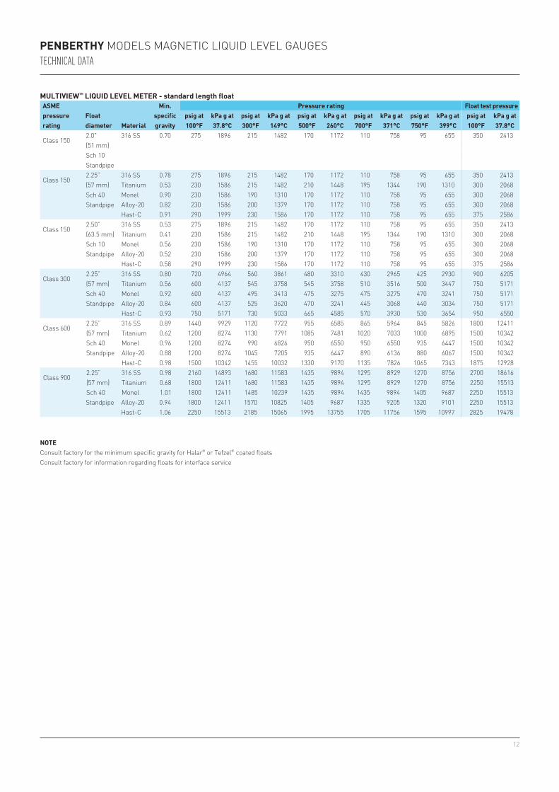
MULTIVIEW™ LIQUID LEVEL METER - standard length floatASME pressure rating
Float diameter Material
Min. specific gravity
Pressure rating Float test pressurepsig at 100°F
kPa g at 37.8°C
psig at 300°F
kPa g at 149°C
psig at 500°F
kPa g at 260°C
psig at 700°F
kPa g at 371°C
psig at 750°F
kPa g at 399°C
psig at 100°F
kPa g at 37.8°C
Class 1502.0" 316 SS 0.70 275 1896 215 1482 170 1172 110 758 95 655 350 2413(51 mm)Sch 10Standpipe
Class 1502.25” 316 SS 0.78 275 1896 215 1482 170 1172 110 758 95 655 350 2413(57 mm) Titanium 0.53 230 1586 215 1482 210 1448 195 1344 190 1310 300 2068Sch 40 Monel 0.90 230 1586 190 1310 170 1172 110 758 95 655 300 2068Standpipe Alloy-20 0.82 230 1586 200 1379 170 1172 110 758 95 655 300 2068
Hast-C 0.91 290 1999 230 1586 170 1172 110 758 95 655 375 2586
Class 1502.50” 316 SS 0.53 275 1896 215 1482 170 1172 110 758 95 655 350 2413(63.5 mm) Titanium 0.41 230 1586 215 1482 210 1448 195 1344 190 1310 300 2068Sch 10 Monel 0.56 230 1586 190 1310 170 1172 110 758 95 655 300 2068Standpipe Alloy-20 0.52 230 1586 200 1379 170 1172 110 758 95 655 300 2068
Hast-C 0.58 290 1999 230 1586 170 1172 110 758 95 655 375 2586
Class 3002.25” 316 SS 0.80 720 4964 560 3861 480 3310 430 2965 425 2930 900 6205(57 mm) Titanium 0.56 600 4137 545 3758 545 3758 510 3516 500 3447 750 5171Sch 40 Monel 0.92 600 4137 495 3413 475 3275 475 3275 470 3241 750 5171Standpipe Alloy-20 0.84 600 4137 525 3620 470 3241 445 3068 440 3034 750 5171
Hast-C 0.93 750 5171 730 5033 665 4585 570 3930 530 3654 950 6550
Class 6002.25” 316 SS 0.89 1440 9929 1120 7722 955 6585 865 5964 845 5826 1800 12411(57 mm) Titanium 0.62 1200 8274 1130 7791 1085 7481 1020 7033 1000 6895 1500 10342Sch 40 Monel 0.96 1200 8274 990 6826 950 6550 950 6550 935 6447 1500 10342Standpipe Alloy-20 0.88 1200 8274 1045 7205 935 6447 890 6136 880 6067 1500 10342
Hast-C 0.98 1500 10342 1455 10032 1330 9170 1135 7826 1065 7343 1875 12928
Class 9002.25” 316 SS 0.98 2160 14893 1680 11583 1435 9894 1295 8929 1270 8756 2700 18616(57 mm) Titanium 0.68 1800 12411 1680 11583 1435 9894 1295 8929 1270 8756 2250 15513Sch 40 Monel 1.01 1800 12411 1485 10239 1435 9894 1435 9894 1405 9687 2250 15513Standpipe Alloy-20 0.94 1800 12411 1570 10825 1405 9687 1335 9205 1320 9101 2250 15513
Hast-C 1.06 2250 15513 2185 15065 1995 13755 1705 11756 1595 10997 2825 19478
NOTEConsult factory for the minimum specific gravity for Halar® or Tefzel® coated floatsConsult factory for information regarding floats for interface service
13
PENBERTHY MAGNETIC LIQUID LEVEL GAUGESTECHNICAL DATA
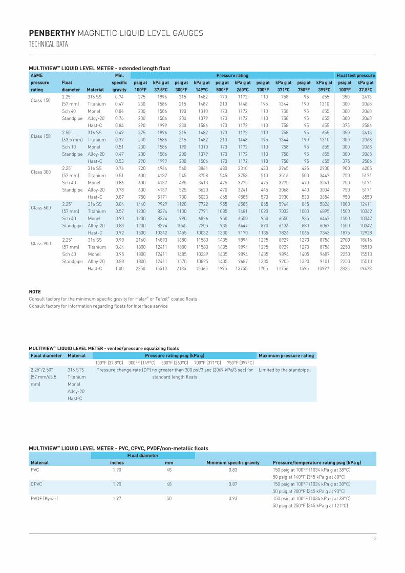
MULTIVIEW™ LIQUID LEVEL METER - extended length floatASME pressure rating
Float diameter Material
Min. specific gravity
Pressure rating Float test pressurepsig at 100°F
kPa g at 37.8°C
psig at 300°F
kPa g at 149°C
psig at 500°F
kPa g at 260°C
psig at 700°F
kPa g at 371°C
psig at 750°F
kPa g at 399°C
psig at 100°F
kPa g at 37.8°C
Class 1502.25” 316 SS 0.74 275 1896 215 1482 170 1172 110 758 95 655 350 2413(57 mm) Titanium 0.47 230 1586 215 1482 210 1448 195 1344 190 1310 300 2068Sch 40 Monel 0.84 230 1586 190 1310 170 1172 110 758 95 655 300 2068Standpipe Alloy-20 0.76 230 1586 200 1379 170 1172 110 758 95 655 300 2068
Hast-C 0.84 290 1999 230 1586 170 1172 110 758 95 655 375 2586
Class 1502.50” 316 SS 0.49 275 1896 215 1482 170 1172 110 758 95 655 350 2413(63.5 mm) Titanium 0.37 230 1586 215 1482 210 1448 195 1344 190 1310 300 2068Sch 10 Monel 0.51 230 1586 190 1310 170 1172 110 758 95 655 300 2068Standpipe Alloy-20 0.47 230 1586 200 1379 170 1172 110 758 95 655 300 2068
Hast-C 0.53 290 1999 230 1586 170 1172 110 758 95 655 375 2586
Class 3002.25” 316 SS 0.76 720 4964 560 3861 480 3310 430 2965 425 2930 900 6205(57 mm) Titanium 0.51 600 4137 545 3758 545 3758 510 3516 500 3447 750 5171Sch 40 Monel 0.86 600 4137 495 3413 475 3275 475 3275 470 3241 750 5171Standpipe Alloy-20 0.78 600 4137 525 3620 470 3241 445 3068 440 3034 750 5171
Hast-C 0.87 750 5171 730 5033 665 4585 570 3930 530 3654 950 6550
Class 6002.25” 316 SS 0.84 1440 9929 1120 7722 955 6585 865 5964 845 5826 1800 12411(57 mm) Titanium 0.57 1200 8274 1130 7791 1085 7481 1020 7033 1000 6895 1500 10342Sch 40 Monel 0.90 1200 8274 990 6826 950 6550 950 6550 935 6447 1500 10342Standpipe Alloy-20 0.83 1200 8274 1045 7205 935 6447 890 6136 880 6067 1500 10342
Hast-C 0.92 1500 10342 1455 10032 1330 9170 1135 7826 1065 7343 1875 12928
Class 9002.25” 316 SS 0.90 2160 14893 1680 11583 1435 9894 1295 8929 1270 8756 2700 18616(57 mm) Titanium 0.64 1800 12411 1680 11583 1435 9894 1295 8929 1270 8756 2250 15513Sch 40 Monel 0.95 1800 12411 1485 10239 1435 9894 1435 9894 1405 9687 2250 15513Standpipe Alloy-20 0.88 1800 12411 1570 10825 1405 9687 1335 9205 1320 9101 2250 15513
Hast-C 1.00 2250 15513 2185 15065 1995 13755 1705 11756 1595 10997 2825 19478
NOTEConsult factory for the minimum specific gravity for Halar® or Tefzel® coated floatsConsult factory for information regarding floats for interface service
MULTIVIEW™ LIQUID LEVEL METER - vented/pressure equalizing floatsFloat diameter Material Pressure rating psig (kPa g) Maximum pressure rating
100°F (37.8°C) 300°F (149°C) 500°F (260°C) 700°F (371°C) 750°F (399°C)2.25”/2.50” (57 mm/63.5 mm)
316 STS Pressure change rate (DP) no greater than 300 psi/3 sec (2069 kPa/3 sec) for standard length floats
Limited by the standpipeTitaniumMonelAlloy-20Hast-C
MULTIVIEW™ LIQUID LEVEL METER - PVC, CPVC, PVDF/non-metallic floats
MaterialFloat diameter
Minimum specific gravity Pressure/temperature rating psig (kPa g)inches mmPVC 1.90 48 0.83 150 psig at 100°F (1034 kPa g at 38°C)
50 psig at 140°F (345 kPa g at 60°C)CPVC 1.90 48 0.87 150 psig at 100°F (1034 kPa g at 38°C)
50 psig at 200°F (345 kPa g at 93°C)PVDF (Kynar) 1.97 50 0.93 150 psig at 100°F (1034 kPa g at 38°C)
50 psig at 250°F (345 kPa g at 121°C)
14
10(254)
10(254)
10(254)
10(254)
4¼(108)
4¼(108)
4¼(108)
4¼(108)
'A' 4½(107)
4⅜(111)
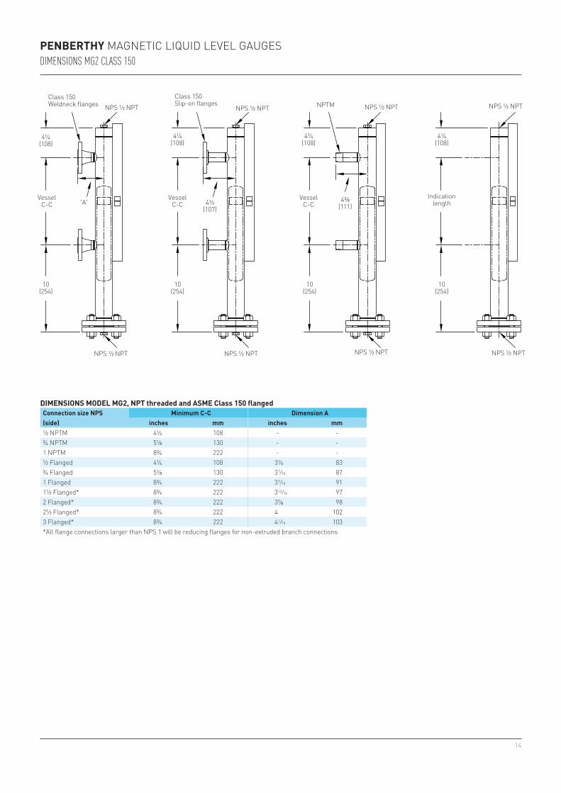
PENBERTHY MAGNETIC LIQUID LEVEL GAUGESDIMENSIONS MG2 CLASS 150
DIMENSIONS MODEL MG2, NPT threaded and ASME Class 150 flangedConnection size NPS(side)
Minimum C-C Dimension Ainches mm inches mm
½ NPTM 4¼ 108 - -¾ NPTM 5⅛ 130 - -1 NPTM 8¾ 222 - -½ Flanged 4¼ 108 3¼ 83¾ Flanged 5⅛ 130 3 7/16 871 Flanged 8¾ 222 3 9/16 911½ Flanged* 8¾ 222 3 13/16 972 Flanged* 8¾ 222 3⅞ 982½ Flanged* 8¾ 222 4 1023 Flanged* 8¾ 222 4 1/16 103*All flange connections larger than NPS 1 will be reducing flanges for non-extruded branch connections
Vessel C-C
Indication length
Class 150Slip-on flanges
Class 150Weldneck flanges NPS ½ NPTNPS ½ NPT NPS ½ NPTNPS ½ NPT
NPS ½ NPTNPS ½ NPT NPS ½ NPTNPS ½ NPT
Vessel C-C
Vessel C-C
NPTM
15
'B' 'B''B''B'
4⅝(117)
4½(114)
5¼(133)
'A'
5¼(133)
'B'
5¼(133)
5¼(133)
5¼(133)
'A'
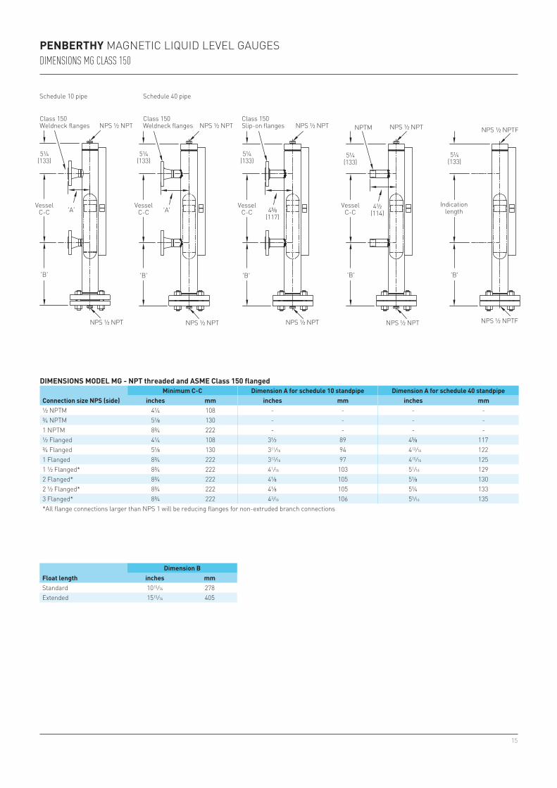
PENBERTHY MAGNETIC LIQUID LEVEL GAUGESDIMENSIONS MG CLASS 150
DIMENSIONS MODEL MG - NPT threaded and ASME Class 150 flanged
Connection size NPS (side)Minimum C-C Dimension A for schedule 10 standpipe Dimension A for schedule 40 standpipe
inches mm inches mm inches mm½ NPTM 4¼ 108 - - - -¾ NPTM 5⅛ 130 - - - -1 NPTM 8¾ 222 - - - -½ Flanged 4¼ 108 3½ 89 4⅝ 117¾ Flanged 5⅛ 130 3 11/16 94 4 13/16 1221 Flanged 8¾ 222 3 13/16 97 4 15/16 1251 ½ Flanged* 8¾ 222 4 1/16 103 5 1/16 1292 Flanged* 8¾ 222 4⅛ 105 5⅛ 1302 ½ Flanged* 8¾ 222 4⅛ 105 5¼ 1333 Flanged* 8¾ 222 4 3/16 106 5 5/16 135*All flange connections larger than NPS 1 will be reducing flanges for non-extruded branch connections
Schedule 10 pipe
Vessel C-C
Indication length
Class 150Slip-on flanges
Class 150Weldneck flanges NPS ½ NPTNPS ½ NPT NPS ½ NPTFNPS ½ NPT
NPS ½ NPTNPS ½ NPT NPS ½ NPTFNPS ½ NPT
Vessel C-C
Vessel C-C
NPTM
Vessel C-C
NPS ½ NPT
Class 150Weldneck flanges
Schedule 40 pipe
NPS ½ NPT
Float lengthDimension B
inches mmStandard 10 15/16 278Extended 15 15/16 405
16
'B' 'B''B' 'B'
5¼(133)
5¼(133)
5¼(133)
4⅝(117)
4½(114)
5¼(133)
'A'
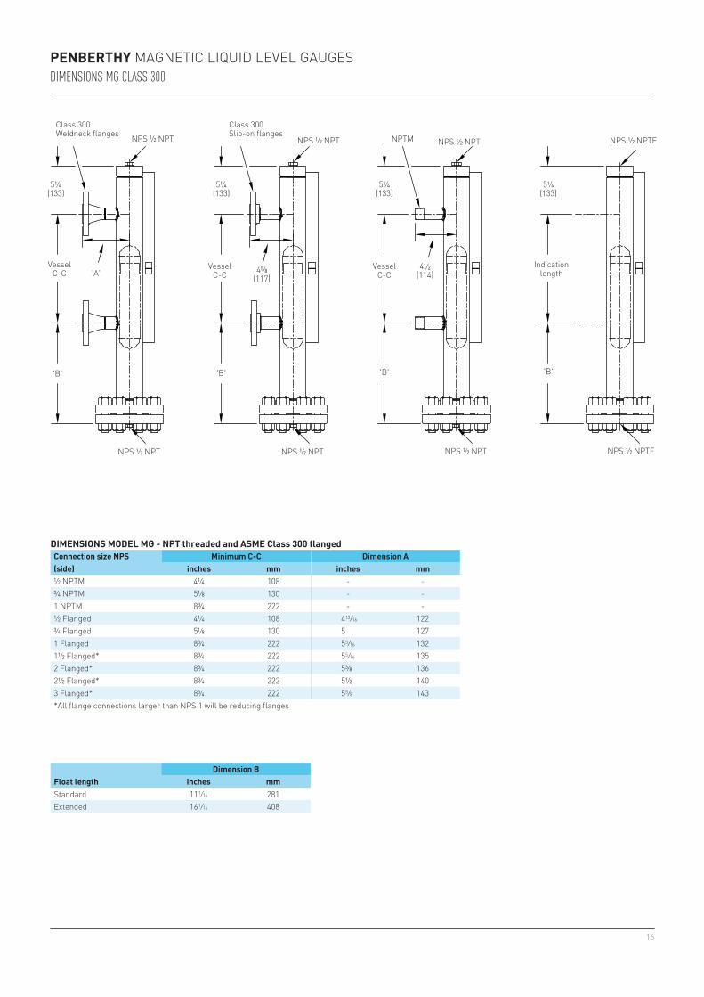
PENBERTHY MAGNETIC LIQUID LEVEL GAUGESDIMENSIONS MG CLASS 300
DIMENSIONS MODEL MG - NPT threaded and ASME Class 300 flangedConnection size NPS(side)
Minimum C-C Dimension Ainches mm inches mm
½ NPTM 4¼ 108 - -¾ NPTM 5⅛ 130 - -1 NPTM 8¾ 222 - -½ Flanged 4¼ 108 4 13/16 122¾ Flanged 5⅛ 130 5 1271 Flanged 8¾ 222 5 3/16 1321½ Flanged* 8¾ 222 5 5/16 1352 Flanged* 8¾ 222 5⅜ 1362½ Flanged* 8¾ 222 5½ 1403 Flanged* 8¾ 222 5 5/8 143*All flange connections larger than NPS 1 will be reducing flanges
Vessel C-C
Indication length
Class 300Slip-on flanges
Class 300Weldneck flanges
NPS ½ NPTNPS ½ NPT NPS ½ NPTFNPS ½ NPT
NPS ½ NPTNPS ½ NPT NPS ½ NPTFNPS ½ NPT
Vessel C-C
Vessel C-C
NPTM
Float lengthDimension B
inches mmStandard 11 1/16 281Extended 16 1/16 408
17
'B' 'B''B' 'B'
5¼(133)
5¼(133)
5¼(133)
5¼(133)
4⅝(117)
4½(114)'A'
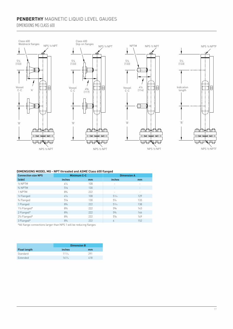
PENBERTHY MAGNETIC LIQUID LEVEL GAUGESDIMENSIONS MG CLASS 600
Vessel C-C
Indication length
Class 600Slip-on flanges
Class 600Weldneck flanges
NPS ½ NPTNPS ½ NPT NPS ½ NPTFNPS ½ NPT
NPS ½ NPTNPS ½ NPT NPS ½ NPTFNPS ½ NPT
Vessel C-C
Vessel C-C
NPTM
DIMENSIONS MODEL MG - NPT threaded and ASME Class 600 flangedConnection size NPS(side)
Minimum C-C Dimension Ainches mm inches mm
½ NPTM 4¼ 108 - -¾ NPTM 5⅛ 130 - -1 NPTM 8¾ 222 - -½ Flanged 4¼ 108 5 1/16 129¾ Flanged 5⅛ 130 5¼ 1331 Flanged 8¾ 222 5 7/16 1381½ Flanged* 8¾ 222 5⅝ 1432 Flanged* 8¾ 222 5¾ 1462½ Flanged* 8¾ 222 5⅞ 1493 Flanged* 8¾ 222 6 152*All flange connections larger than NPS 1 will be reducing flanges
Float lengthDimension B
inches mmStandard 11 7/16 291Extended 16 7/16 418
18
'B' 'B''B' 'B'
5¼(133)
5¼(133)
5¼(133)
5¼(133)
4 11/16
(119)4½
(114)'A'
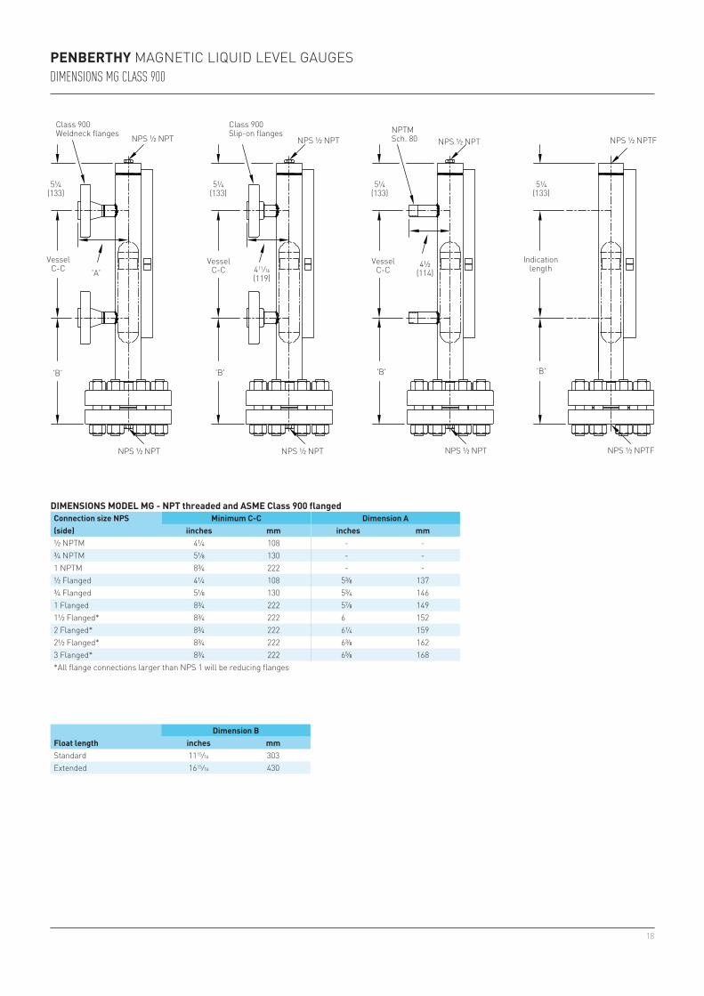
PENBERTHY MAGNETIC LIQUID LEVEL GAUGESDIMENSIONS MG CLASS 900
VesselC-C
Indication length
Class 900Slip-on flanges
Class 900Weldneck flanges
NPS ½ NPTNPS ½ NPT NPS ½ NPTFNPS ½ NPT
NPS ½ NPTNPS ½ NPT NPS ½ NPTFNPS ½ NPT
VesselC-C
VesselC-C
NPTMSch. 80
DIMENSIONS MODEL MG - NPT threaded and ASME Class 900 flangedConnection size NPS(side)
Minimum C-C Dimension Aiinches mm inches mm
½ NPTM 4¼ 108 - -¾ NPTM 5⅛ 130 - -1 NPTM 8¾ 222 - -½ Flanged 4¼ 108 5⅜ 137¾ Flanged 5⅛ 130 5¾ 1461 Flanged 8¾ 222 5⅞ 1491½ Flanged* 8¾ 222 6 1522 Flanged* 8¾ 222 6¼ 1592½ Flanged* 8¾ 222 6⅜ 1623 Flanged* 8¾ 222 6⅝ 168*All flange connections larger than NPS 1 will be reducing flanges
Float lengthDimension B
inches mmStandard 11 15/16 303Extended 16 15/16 430
19
4⅜(111)
7 3/16
(183)
'A' 4 7/16
(113)
7 3/16
(183)7 3/16
(183)
4⅜(111)
4⅜(111)
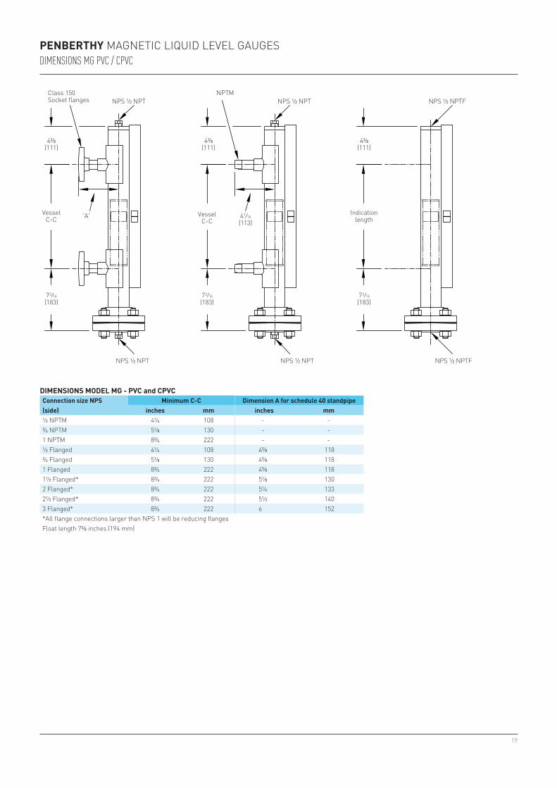
PENBERTHY MAGNETIC LIQUID LEVEL GAUGESDIMENSIONS MG PVC / CPVC
DIMENSIONS MODEL MG - PVC and CPVCConnection size NPS(side)
Minimum C-C Dimension A for schedule 40 standpipeinches mm inches mm
½ NPTM 4¼ 108 - -¾ NPTM 5⅛ 130 - -1 NPTM 8¾ 222 - -½ Flanged 4¼ 108 4⅝ 118¾ Flanged 5⅛ 130 4⅝ 1181 Flanged 8¾ 222 4⅝ 1181½ Flanged* 8¾ 222 5⅛ 1302 Flanged* 8¾ 222 5¼ 1332½ Flanged* 8¾ 222 5½ 1403 Flanged* 8¾ 222 6 152*All flange connections larger than NPS 1 will be reducing flangesFloat length 7⅝ inches (194 mm)
VesselC-C
Indication length
Class 150Socket flanges NPS ½ NPT NPS ½ NPTFNPS ½ NPT
NPS ½ NPT NPS ½ NPTFNPS ½ NPT
VesselC-C
NPTM
20
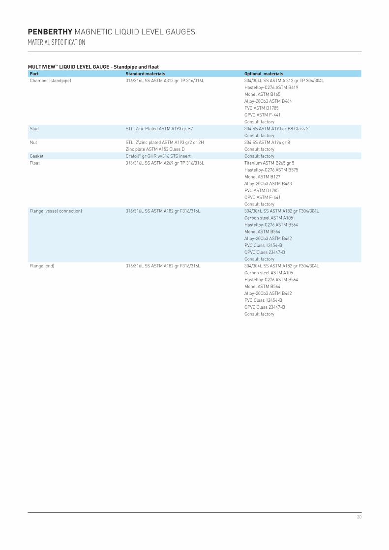
PENBERTHY MAGNETIC LIQUID LEVEL GAUGESMATERIAL SPECIFICATION
MULTIVIEW™ LIQUID LEVEL GAUGE - Standpipe and floatPart Standard materials Optional materialsChamber (standpipe) 316/316L SS ASTM A312 gr TP 316/316L 304/304L SS ASTM A 312 gr TP 304/304L
Hastelloy-C276 ASTM B619Monel ASTM B165Alloy-20Cb3 ASTM B464PVC ASTM D1785CPVC ASTM F-441Consult factory
Stud STL, Zinc Plated ASTM A193 gr B7 304 SS ASTM A193 gr B8 Class 2Consult factory
Nut STL, Z\zinc plated ASTM A193 gr2 or 2H 304 SS ASTM A194 gr 8Zinc plate ASTM A153 Class D Consult factory
Gasket Grafoil® gr GHR w/316 STS insert Consult factoryFloat 316/316L SS ASTM A269 gr TP 316/316L Titanium ASTM B265 gr 5
Hastelloy-C276 ASTM B575Monel ASTM B127Alloy-20Cb3 ASTM B463PVC ASTM D1785CPVC ASTM F-441Consult factory
Flange (vessel connection) 316/316L SS ASTM A182 gr F316/316L 304/304L SS ASTM A182 gr F304/304LCarbon steel ASTM A105Hastelloy-C276 ASTM B564Monel ASTM B564Alloy-20Cb3 ASTM B462PVC Class 12454-BCPVC Class 23447-BConsult factory
Flange (end) 316/316L SS ASTM A182 gr F316/316L 304/304L SS ASTM A182 gr F304/304LCarbon steel ASTM A105Hastelloy-C276 ASTM B564Monel ASTM B564Alloy-20Cb3 ASTM B462PVC Class 12454-BCPVC Class 23447-BConsult factory
21
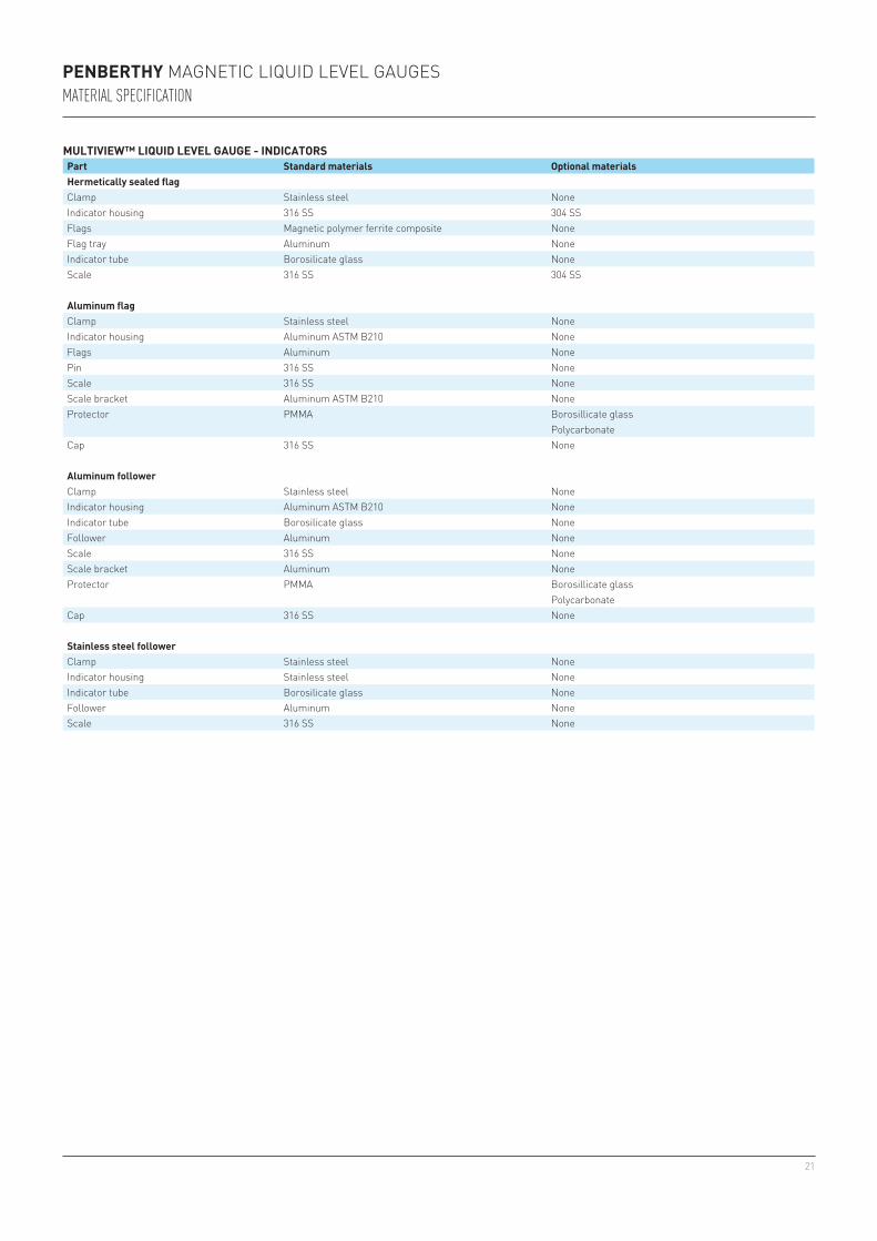
PENBERTHY MAGNETIC LIQUID LEVEL GAUGESMATERIAL SPECIFICATION
MULTIVIEW™ LIQUID LEVEL GAUGE - INDICATORSPart Standard materials Optional materialsHermetically sealed flagClamp Stainless steel NoneIndicator housing 316 SS 304 SSFlags Magnetic polymer ferrite composite NoneFlag tray Aluminum NoneIndicator tube Borosilicate glass NoneScale 316 SS 304 SS
Aluminum flagClamp Stainless steel NoneIndicator housing Aluminum ASTM B210 NoneFlags Aluminum NonePin 316 SS NoneScale 316 SS NoneScale bracket Aluminum ASTM B210 NoneProtector PMMA Borosillicate glass
PolycarbonateCap 316 SS None
Aluminum followerClamp Stainless steel NoneIndicator housing Aluminum ASTM B210 NoneIndicator tube Borosilicate glass NoneFollower Aluminum NoneScale 316 SS NoneScale bracket Aluminum NoneProtector PMMA Borosillicate glass
PolycarbonateCap 316 SS None
Stainless steel followerClamp Stainless steel NoneIndicator housing Stainless steel NoneIndicator tube Borosilicate glass NoneFollower Aluminum NoneScale 316 SS None
22
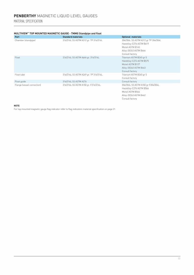
PENBERTHY MAGNETIC LIQUID LEVEL GAUGESMATERIAL SPECIFICATION
MULTIVIEW™ TOP MOUNTED MAGNETIC GAUGE - TMMG Standpipe and floatPart Standard materials Optional materialsChamber (standpipe) 316/316L SS ASTM A312 gr. TP 316/316L 304/304L SS ASTM A312 gr TP 304/304L
Hastelloy-C276 ASTM B619Monel ASTM B165Alloy-20Cb3 ASTM B464Consult factory
Float 316/316L SS ASTM A666 gr. 316/316L Titanium ASTM B265 gr 5Hastelloy-C276 ASTM B575Monel ASTM B127Alloy-20Cb3 ASTM B463Consult factory
Float tube 316/316L SS ASTM A269 gr. TP 316/316L Titanium ASTM B265 gr 5Consult factory
Float guide 316/316L SS ASTM A276 Consult factoryFlange (vessel connection) 316/316L SS ASTM A182 gr. F316/316L 304/304L SS ASTM A182 gr F304/304L
Hastelloy-C276 ASTM B564Monel ASTM B564Alloy-20Cb3 ASTM B462Consult factory
NOTEFor top mounted magnetic gauge flag indicator refer to flag indicators material specification on page 21.
23
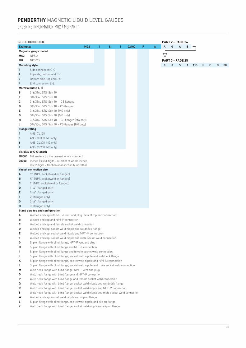
PENBERTHY MAGNETIC LIQUID LEVEL GAUGESORDERING INFORMATION MG2 / MG PART 1
SELECTION GUIDE PART 2 - PAGE 24Example: MG2 1 S 1 02400 F A A G A BMagnetic gauge modelMG2 NPS 2MG NPS 2.5 PART 3 - PAGE 25Mounting style 0 0 S 1 115 H F N 001 Side connection C-C2 Top side, bottom end C-E3 Bottom side, top end E-C4 End connection E-EMaterial (note 1, 2)S 316/316L STS (Sch 10)F 304/304L STS (Sch 10)C 316/316L STS (Sch 10) - CS flangesD 304/304L STS (Sch 10) - CS flangesE 316/316L STS (Sch 40) (MG only)G 304/304L STS (Sch 40) (MG only)H 316/316L STS (Sch 40) - CS flanges (MG only)J 304/304L STS (Sch 40) - CS flanges (MG only)Flange rating1 ANSI CL1503 ANSI CL300 (MG only)6 ANSI CL600 (MG only)9 ANSI CL900 (MG only)Visibilty or C-C lengthM0000 Millimeters (to the nearest whole number)00000 Inches (first 3 digits = number of whole inches,
last 2 digits = fraction of an inch in hundreths)Vessel connection sizeA ½" (NPT, socketweld or flanged)B ¾" (NPT, socketweld or flanged)C 1" (NPT, socketweld or flanged)D 1-¼" (flanged only)E 1-½" (flanged only)F 2" (flanged only)G 2-½" (flanged only)H 3" (flanged only)Stand pipe top end configurationA Welded end cap with NPT-F vent and plug (default top end connection)B Welded end cap and NPT-F connectionC Welded end cap and female socket weld connectionD Welded end cap, socket weld nipple and weldneck flangeE Welded end cap, socket weld nipple and NPT-M connectionF Welded end cap, socket weld nipple and male socket weld connectionG Slip on flange with blind flange, NPT-F vent and plugH Slip on flange with blind flange and NPT-F connectionI Slip on flange with blind flange and female socket weld connectionJ Slip on flange with blind flange, socket weld nipple and weldneck flangeK Slip on flange with blind flange, socket weld nipple and NPT-M connectionL Slip on flange with blind flange, socket weld nipple and male socket weld connectionM Weld neck flange with blind flange, NPT-F vent and plugO Weld neck flange with blind flange and NPT-F connectionP Weld neck flange with blind flange and female socket weld connectionQ Weld neck flange with blind flange, socket weld nipple and weldneck flangeR Weld neck flange with blind flange, socket weld nipple and NPT-M connectionS Weld neck flange with blind flange, socket weld nipple and male socket weld connectionW Welded end cap, socket weld nipple and slip on flangeZ Slip on flange with blind flange, socket weld nipple and slip on flangeY Weld neck flange with blind flange, socket weld nipple and slip on flange
24
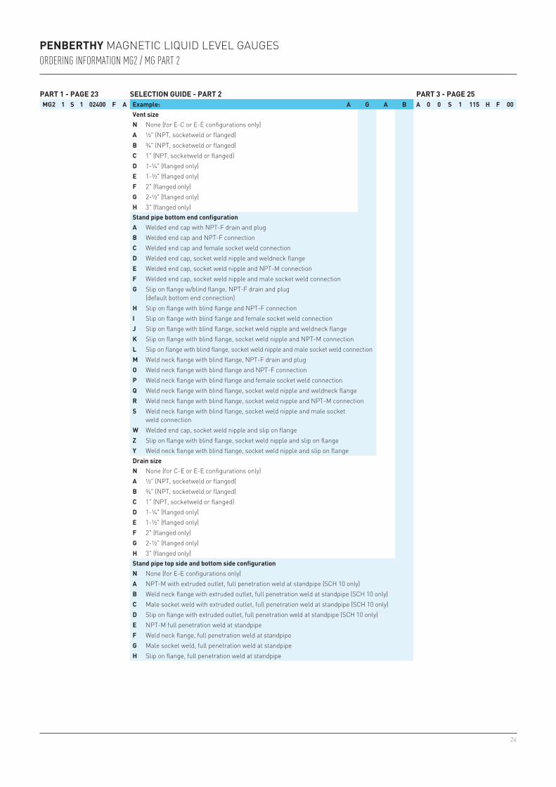
PENBERTHY MAGNETIC LIQUID LEVEL GAUGESORDERING INFORMATION MG2 / MG PART 2
PART 1 - PAGE 23 SELECTION GUIDE - PART 2 PART 3 - PAGE 25MG2 1 S 1 02400 F A Example: A G A B A 0 0 S 1 115 H F 00
Vent sizeN None (for E-C or E-E configurations only)A ½" (NPT, socketweld or flanged)B ¾" (NPT, socketweld or flanged)C 1" (NPT, socketweld or flanged)D 1-¼" (flanged only)E 1-½" (flanged only)F 2" (flanged only)G 2-½" (flanged only)H 3" (flanged only)Stand pipe bottom end configurationA Welded end cap with NPT-F drain and plugB Welded end cap and NPT-F connectionC Welded end cap and female socket weld connectionD Welded end cap, socket weld nipple and weldneck flangeE Welded end cap, socket weld nipple and NPT-M connectionF Welded end cap, socket weld nipple and male socket weld connectionG Slip on flange w/blind flange, NPT-F drain and plug
(default bottom end connection)H Slip on flange with blind flange and NPT-F connectionI Slip on flange with blind flange and female socket weld connectionJ Slip on flange with blind flange, socket weld nipple and weldneck flangeK Slip on flange with blind flange, socket weld nipple and NPT-M connectionL Slip on flange with blind flange, socket weld nipple and male socket weld connectionM Weld neck flange with blind flange, NPT-F drain and plugO Weld neck flange with blind flange and NPT-F connectionP Weld neck flange with blind flange and female socket weld connectionQ Weld neck flange with blind flange, socket weld nipple and weldneck flangeR Weld neck flange with blind flange, socket weld nipple and NPT-M connectionS Weld neck flange with blind flange, socket weld nipple and male socket
weld connectionW Welded end cap, socket weld nipple and slip on flangeZ Slip on flange with blind flange, socket weld nipple and slip on flangeY Weld neck flange with blind flange, socket weld nipple and slip on flangeDrain sizeN None (for C-E or E-E configurations only)A ½" (NPT, socketweld or flanged)B ¾" (NPT, socketweld or flanged)C 1" (NPT, socketweld or flanged)D 1-¼" (flanged only)E 1-½" (flanged only)F 2" (flanged only)G 2-½" (flanged only)H 3" (flanged only)Stand pipe top side and bottom side configurationN None (for E-E configurations only)A NPT-M with extruded outlet, full penetration weld at standpipe (SCH 10 only)B Weld neck flange with extruded outlet, full penetration weld at standpipe (SCH 10 only)C Male socket weld with extruded outlet, full penetration weld at standpipe (SCH 10 only)D Slip on flange with extruded outlet, full penetration weld at standpipe (SCH 10 only)E NPT-M full penetration weld at standpipeF Weld neck flange, full penetration weld at standpipeG Male socket weld, full penetration weld at standpipeH Slip on flange, full penetration weld at standpipe
25
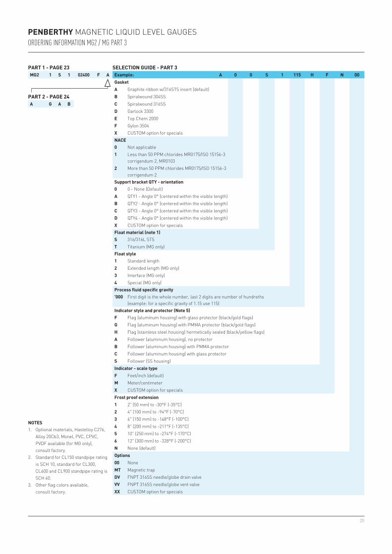
PENBERTHY MAGNETIC LIQUID LEVEL GAUGESORDERING INFORMATION MG2 / MG PART 3
PART 1 - PAGE 23 SELECTION GUIDE - PART 3MG2 1 S 1 02400 F A Example: A 0 0 S 1 115 H F N 00
GasketA Graphite ribbon w/316STS insert (default)
PART 2 - PAGE 24 B Spiralwound 304SSA G A B C Spiralwound 316SS
D Garlock 3300E Top Chem 2000F Gylon 3504X CUSTOM option for specialsNACE0 Not applicable1 Less than 50 PPM chlorides MR0175/ISO 15156-3
corrigendum 2, MR01032 More than 50 PPM chlorides MR0175/ISO 15156-3
corrigendum 2Support bracket QTY - orientation0 0 - None (Default)A QTY1 - Angle 0° (centered within the visible length)B QTY2 - Angle 0° (centered within the visible length)C QTY3 - Angle 0° (centered within the visible length)D QTY4 - Angle 0° (centered within the visible length)X CUSTOM option for specialsFloat material (note 1)S 316/316L STST Titanium (MG only) Float style1 Standard length2 Extended length (MG only)3 Interface (MG only)4 Special (MG only)Process fluid specific gravity'000 First digit is the whole number, last 2 digits are number of hundreths
(example: for a specific gravity of 1.15 use 115)Indicator style and protector (Note 5)
NOTES1. Optional materials, Hastelloy C276,
Alloy 20Cb3, Monel, PVC, CPVC, PVDF available (for MG only), consult factory.
2. Standard for CL150 standpipe rating is SCH 10, standard for CL300, CL600 and CL900 standpipe rating is SCH 40.
3. Other flag colors available, consult factory.
F Flag (aluminum housing) with glass protector (black/gold flags)G Flag (aluminum housing) with PMMA protector (black/gold flags)H Flag (stainless steel housing) hermetically sealed (black/yellow flags)A Follower (aluminum housing), no protectorB Follower (aluminum housing) with PMMA protectorC Follower (aluminum housing) with glass protectorS Follower (SS housing)Indicator - scale typeF Feet/inch (default)M Meter/centimeterX CUSTOM option for specialsFrost proof extension1 2" (50 mm) to -30°F (-35°C)2 4" (100 mm) to -94°F (-70°C)3 6" (150 mm) to -148°F (-100°C)4 8" (200 mm) to -211°F (-135°C)5 10" (250 mm) to -274°F (-170°C)6 12" (300 mm) to -328°F (-200°C)N None (default)Options00 NoneMT Magnetic trapDV FNPT 316SS needle/globe drain valveVV FNPT 316SS needle/globe vent valveXX CUSTOM option for specials
26
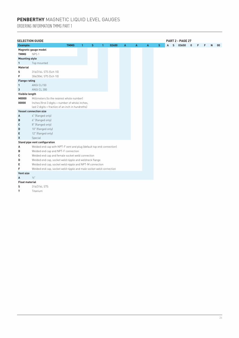
PENBERTHY MAGNETIC LIQUID LEVEL GAUGESORDERING INFORMATION TMMG PART 1
SELECTION GUIDE PART 2 - PAGE 27Example: TMMG 1 S 1 02400 A A A S A S 03650 0 F F N 00Magnetic gauge modelTMMG NPS 1Mounting style1 Top mountedMaterialS 316/316L STS (Sch 10)F 304/304L STS (Sch 10)Flange rating1 ANSI CL1503 ANSI CL 300Visibile lengthM0000 Millimeters (to the nearest whole number)00000 Inches (first 3 digits = number of whole inches,
last 2 digits = fraction of an inch in hundreths)Vessel connection sizeA 4" (flanged only)B 6" (flanged only)C 8" (flanged only)D 10" (flanged only)E 12" (flanged only)X SpecialStand pipe vent configurationA Welded end cap with NPT-F vent and plug (default top end connection) B Welded end cap and NPT-F connectionC Welded end cap and female socket weld connectionD Welded end cap, socket weld nipple and weldneck flangeE Welded end cap, socket weld nipple and NPT-M connectionF Welded end cap, socket weld nipple and male socket weld connectionVent sizeA ½"Float materialS 316/316L STST Titanium
27
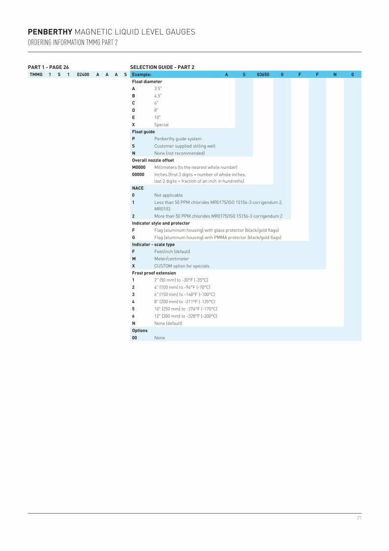
PENBERTHY MAGNETIC LIQUID LEVEL GAUGESORDERING INFORMATION TMMG PART 2
PART 1 - PAGE 26 SELECTION GUIDE - PART 2TMMG 1 S 1 02400 A A A S Example: A S 03650 0 F F N 0
Float diameterA 3.5"B 4.5"C 6"D 8"E 10"X SpecialFloat guideP Penberthy guide systemS Customer supplied stilling wellN None (not recommended)Overall nozzle offsetM0000 Millimeters (to the nearest whole number)00000 Inches (first 3 digits = number of whole inches,
last 2 digits = fraction of an inch in hundreths)NACE0 Not applicable1 Less than 50 PPM chlorides MR0175/ISO 15156-3 corrigendum 2,
MR01032 More than 50 PPM chlorides MR0175/ISO 15156-3 corrigendum 2Indicator style and protectorF Flag (aluminum housing) with glass protector (black/gold flags)G Flag (aluminum housing) with PMMA protector (black/gold flags)Indicator - scale typeF Feet/inch (default)M Meter/centimeterX CUSTOM option for specialsFrost proof extension1 2" (50 mm) to -30°F (-35°C)2 4" (100 mm) to -94°F (-70°C) 3 6" (150 mm) to -148°F (-100°C) 4 8" (200 mm) to -211°F (-135°C) 5 10" (250 mm) to -274°F (-170°C) 6 12" (300 mm) to -328°F (-200°C)N None (default)Options00 None
28
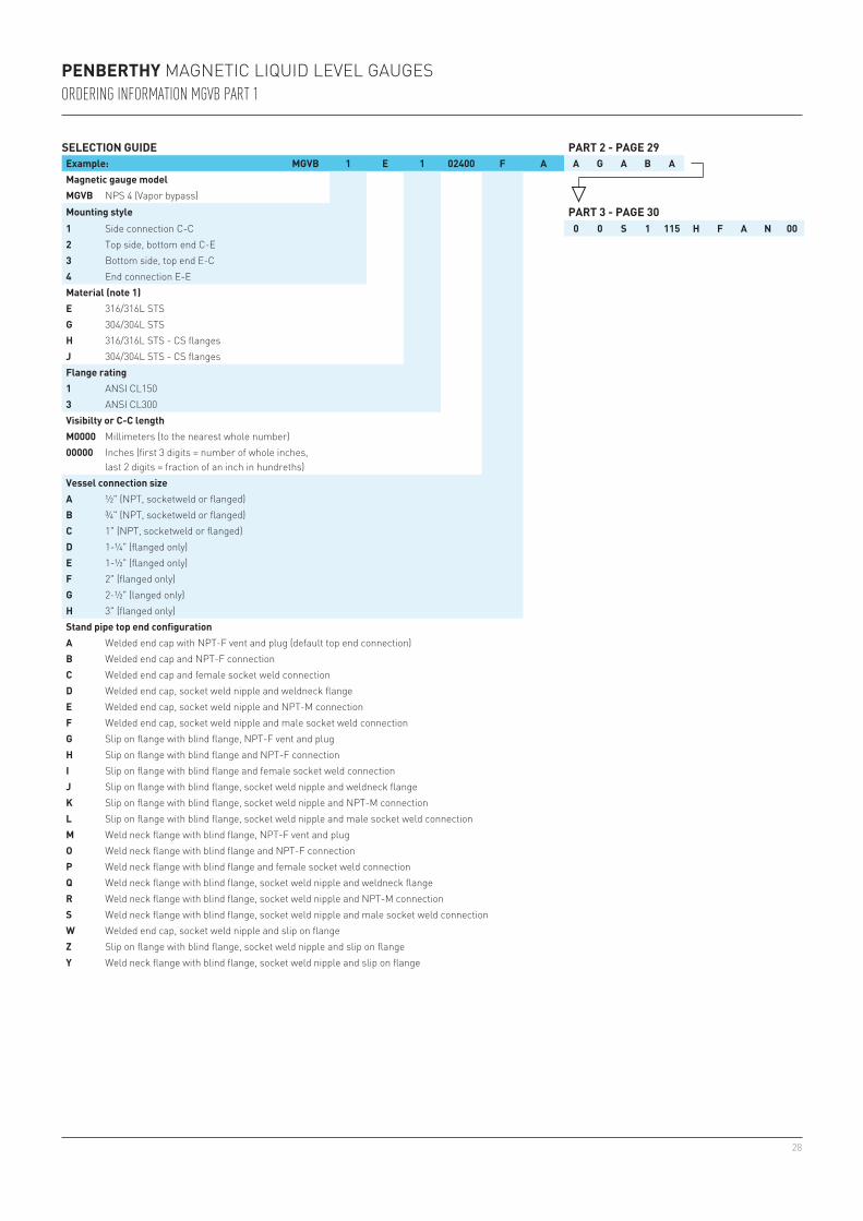
SELECTION GUIDE PART 2 - PAGE 29Example: MGVB 1 E 1 02400 F A A G A B AMagnetic gauge modelMGVB NPS 4 (Vapor bypass)Mounting style PART 3 - PAGE 301 Side connection C-C 0 0 S 1 115 H F A N 002 Top side, bottom end C-E3 Bottom side, top end E-C4 End connection E-EMaterial (note 1)E 316/316L STSG 304/304L STSH 316/316L STS - CS flangesJ 304/304L STS - CS flangesFlange rating1 ANSI CL1503 ANSI CL300Visibilty or C-C lengthM0000 Millimeters (to the nearest whole number)00000 Inches (first 3 digits = number of whole inches,
last 2 digits = fraction of an inch in hundreths)Vessel connection sizeA ½" (NPT, socketweld or flanged)B ¾" (NPT, socketweld or flanged)C 1" (NPT, socketweld or flanged)D 1-¼" (flanged only)E 1-½" (flanged only)F 2" (flanged only)G 2-½" (langed only)H 3" (flanged only)Stand pipe top end configurationA Welded end cap with NPT-F vent and plug (default top end connection)B Welded end cap and NPT-F connectionC Welded end cap and female socket weld connectionD Welded end cap, socket weld nipple and weldneck flangeE Welded end cap, socket weld nipple and NPT-M connectionF Welded end cap, socket weld nipple and male socket weld connectionG Slip on flange with blind flange, NPT-F vent and plugH Slip on flange with blind flange and NPT-F connectionI Slip on flange with blind flange and female socket weld connectionJ Slip on flange with blind flange, socket weld nipple and weldneck flangeK Slip on flange with blind flange, socket weld nipple and NPT-M connectionL Slip on flange with blind flange, socket weld nipple and male socket weld connectionM Weld neck flange with blind flange, NPT-F vent and plugO Weld neck flange with blind flange and NPT-F connectionP Weld neck flange with blind flange and female socket weld connectionQ Weld neck flange with blind flange, socket weld nipple and weldneck flangeR Weld neck flange with blind flange, socket weld nipple and NPT-M connectionS Weld neck flange with blind flange, socket weld nipple and male socket weld connectionW Welded end cap, socket weld nipple and slip on flangeZ Slip on flange with blind flange, socket weld nipple and slip on flangeY Weld neck flange with blind flange, socket weld nipple and slip on flange
PENBERTHY MAGNETIC LIQUID LEVEL GAUGESORDERING INFORMATION MGVB PART 1
29
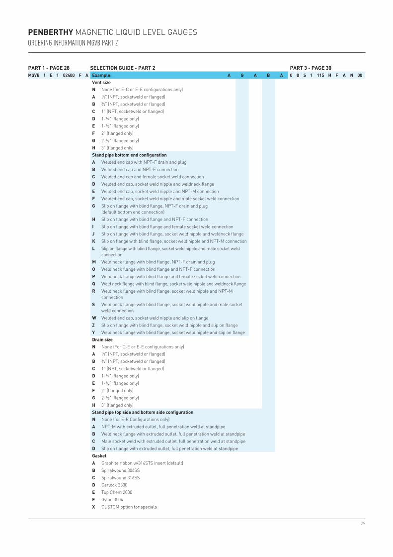
PART 1 - PAGE 28 SELECTION GUIDE - PART 2 PART 3 - PAGE 30MGVB 1 E 1 02400 F A Example: A G A B A 0 0 S 1 115 H F A N 00
Vent sizeN None (for E-C or E-E configurations only)A ½" (NPT, socketweld or flanged)B ¾" (NPT, socketweld or flanged)C 1" (NPT, socketweld or flanged)D 1-¼" (flanged only)E 1-½" (flanged only)F 2" (flanged only)G 2-½" (flanged only)H 3" (flanged only)Stand pipe bottom end configurationA Welded end cap with NPT-F drain and plugB Welded end cap and NPT-F connectionC Welded end cap and female socket weld connectionD Welded end cap, socket weld nipple and weldneck flangeE Welded end cap, socket weld nipple and NPT-M connectionF Welded end cap, socket weld nipple and male socket weld connectionG Slip on flange with blind flange, NPT-F drain and plug
(default bottom end connection)H Slip on flange with blind flange and NPT-F connectionI Slip on flange with blind flange and female socket weld connectionJ Slip on flange with blind flange, socket weld nipple and weldneck flangeK Slip on flange with blind flange, socket weld nipple and NPT-M connectionL Slip on flange with blind flange, socket weld nipple and male socket weld
connectionM Weld neck flange with blind flange, NPT-F drain and plugO Weld neck flange with blind flange and NPT-F connectionP Weld neck flange with blind flange and female socket weld connectionQ Weld neck flange with blind flange, socket weld nipple and weldneck flangeR Weld neck flange with blind flange, socket weld nipple and NPT-M
connectionS Weld neck flange with blind flange, socket weld nipple and male socket
weld connectionW Welded end cap, socket weld nipple and slip on flangeZ Slip on flange with blind flange, socket weld nipple and slip on flangeY Weld neck flange with blind flange, socket weld nipple and slip on flangeDrain sizeN None (For C-E or E-E configurations only)A ½" (NPT, socketweld or flanged) B ¾" (NPT, socketweld or flanged)C 1" (NPT, socketweld or flanged)D 1-¼" (flanged only)E 1-½" (flanged only)F 2" (flanged only)G 2-½" (flanged only)H 3" (flanged only)Stand pipe top side and bottom side configurationN None (for E-E Configurations only)A NPT-M with extruded outlet, full penetration weld at standpipeB Weld neck flange with extruded outlet, full penetration weld at standpipeC Male socket weld with extruded outlet, full penetration weld at standpipe D Slip on flange with extruded outlet, full penetration weld at standpipeGasketA Graphite ribbon w/316STS insert (default)B Spiralwound 304SSC Spiralwound 316SSD Garlock 3300E Top Chem 2000F Gylon 3504X CUSTOM option for specials
PENBERTHY MAGNETIC LIQUID LEVEL GAUGESORDERING INFORMATION MGVB PART 2
30
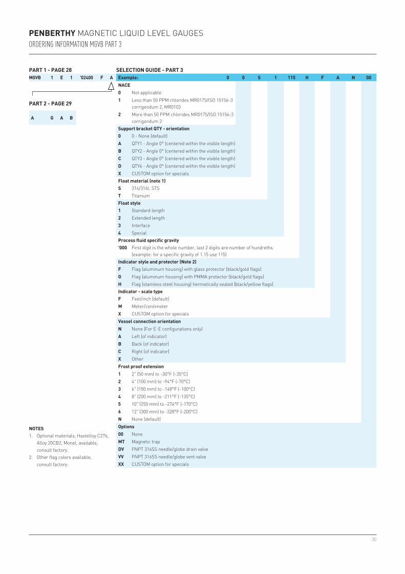
PART 1 - PAGE 28 SELECTION GUIDE - PART 3MGVB 1 E 1 '02400 F A Example: 0 0 S 1 115 H F A N 00
NACE0 Not applicable
PART 2 - PAGE 29 1 Less than 50 PPM chlorides MR0175/ISO 15156-3 corrigendum 2, MR0103
A G A B2 More than 50 PPM chlorides MR0175/ISO 15156-3
corrigendum 2Support bracket QTY - orientation0 0 - None (default)A QTY1 - Angle 0° (centered within the visible length)B QTY2 - Angle 0° (centered within the visible length)C QTY3 - Angle 0° (centered within the visible length)D QTY4 - Angle 0° (centered within the visible length)X CUSTOM option for specialsFloat material (note 1)S 316/316L STST TitaniumFloat style1 Standard length2 Extended length3 Interface4 SpecialProcess fluid specific gravity'000 First digit is the whole number, last 2 digits are number of hundreths
(example: for a specific gravity of 1.15 use 115)Indicator style and protector (Note 2)F Flag (aluminum housing) with glass protector (black/gold flags)G Flag (aluminum housing) with PMMA protector (black/gold flags)H Flag (stainless steel housing) hermetically sealed (black/yellow flags)Indicator - scale type
NOTES1. Optional materials, Hastelloy C276,
Alloy 20CB2, Monel, available, consult factory.
2. Other flag colors available, consult factory.
F Feet/inch (default)M Meter/centimeterX CUSTOM option for specialsVessel connection orientationN None (For E-E configurations only)A Left (of indicator)B Back (of indicator)C Right (of indicator)X OtherFrost proof extension1 2" (50 mm) to -30°F (-35°C)2 4" (100 mm) to -94°F (-70°C)3 6" (150 mm) to -148°F (-100°C)4 8" (200 mm) to -211°F (-135°C)5 10" (250 mm) to -274°F (-170°C)6 12" (300 mm) to -328°F (-200°C)N None (default)Options00 NoneMT Magnetic trapDV FNPT 316SS needle/globe drain valveVV FNPT 316SS needle/globe vent valveXX CUSTOM option for specials
PENBERTHY MAGNETIC LIQUID LEVEL GAUGESORDERING INFORMATION MGVB PART 3
31
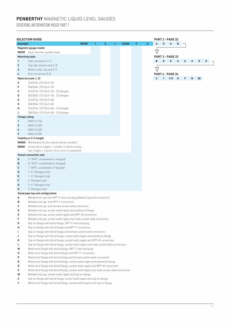
SELECTION GUIDE PART 2 - PAGE 32Example: MGGR 1 S 1 02400 F A A G A BMagnetic gauge modelMGGR Dual chamber guided radarMounting style PART 3 - PAGE 331 Side connection C-C B D E A A A O O2 Top side, bottom end C-E3 Bottom side, top end E-C4 End connection E-E PART 4 - PAGE 34Material (note 1, 2) S 1 115 H F N 00S 316/316L STS (Sch 10)F 304/304L STS (Sch 10)C 316/316L STS (Sch 10) - CS flangesD 304/304L STS (Sch 10) - CS flangesE 316/316L STS (Sch 40)G 304/304L STS (Sch 40)H 316/316L STS (Sch 40) - CS flangesJ 304/304L STS (Sch 40) - CS flangesFlange rating1 ANSI CL1503 ANSI CL3006 ANSI CL6009 ANSI CL900Visibilty or C-C lengthM0000 Millimeters (to the nearest whole number)00000 Inches (first 3 digits = number of whole inches,
last 2 digits = fraction of an inch in hundreths)Vessel connection sizeA ½" (NPT, socketweld or flanged)B ¾" (NPT, socketweld or flanged)C 1" (NPT, socketweld or flanged)D 1-¼" (flanged only)E 1-½" (flanged only)F 2" (flanged only)G 2-½" (flanged only)H 3" (flanged only)Stand pipe top end configurationA Welded end cap with NPT-F vent and plug (default top end connection)B Welded end cap and NPT-F connectionC Welded end cap and female socket weld connectionD Welded end cap, socket weld nipple and weldneck flangeE Welded end cap, socket weld nipple and NPT-M connectionF Welded end cap, socket weld nipple and male socket weld connectionG Slip on flange with blind flange, NPT-F vent and plugH Slip on flange with blind flange and NPT-F connectionI Slip on flange with blind flange and female socket weld connectionJ Slip on flange with blind flange, socket weld nipple and weldneck flangeK Slip on flange with blind flange, socket weld nipple and NPT-M connectionL Slip on flange with blind flange, socket weld nipple and male socket weld connectionM Weld neck flange with blind flange, NPT-F vent and plugO Weld neck flange with blind flange and NPT-F connectionP Weld neck flange with blind flange and female socket weld connectionQ Weld neck flange with blind flange, socket weld nipple and weldneck flangeR Weld neck flange with blind flange, socket weld nipple and NPT-M connectionS Weld neck flange with blind flange, socket weld nipple and male socket weld connectionW Welded end cap, socket weld nipple and slip on flangeZ Slip on flange with blind flange, socket weld nipple and slip on flangeY Weld neck flange with blind flange, socket weld nipple and slip on flange
PENBERTHY MAGNETIC LIQUID LEVEL GAUGESORDERING INFORMATION MGGR PART 1
32
PART 1 - PAGE 31 SELECTION GUIDE - PART 2 PART 3 - PAGE 33MGGR 1 S 1 02400 F A Example: A G A B B D E A A A O O
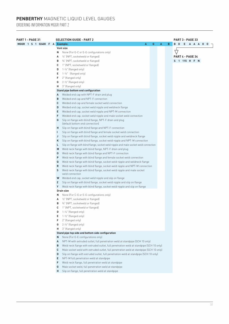
Vent sizeN None (For E-C or E-E configurations only)A ½" (NPT, socketweld or flanged) PART 4 - PAGE 34B ¾" (NPT, socketweld or flanged) S 1 115 H F NC 1" (NPT, socketweld or flanged)D 1-¼" (flanged only)E 1-½" (flanged only)F 2" (flanged only)G 2-½" (flanged only)H 3" (flanged only)Stand pipe bottom end configurationA Welded end cap with NPT-F drain and plugB Welded end cap and NPT-F connectionC Welded end cap and female socket weld connectionD Welded end cap, socket weld nipple and weldneck flangeE Welded end cap, socket weld nipple and NPT-M connectionF Welded end cap, socket weld nipple and male socket weld connectionG Slip on flange witn blind flange, NPT-F drain and plug
(default bottom end connection)H Slip on flange with blind flange and NPT-F connectionI Slip on flange with blind flange and female socket weld connectionJ Slip on flange with blind flange, socket weld nipple and weldneck flangeK Slip on flange with blind flange, socket weld nipple and NPT-M connectionL Slip on flange with blind flange, socket weld nipple and male socket weld connectionM Weld neck flange with blind flange, NPT-F drain and plugO Weld neck flange with blind flange and NPT-F connectionP Weld neck flange with blind flange and female socket weld connectionQ Weld neck flange with blind flange, socket weld nipple and weldneck flangeR Weld neck flange with blind flange, socket weld nipple and NPT-M connectionS Weld neck flange with blind flange, socket weld nipple and male socket
weld connectionW Welded end cap, socket weld nipple and slip on flangeZ Slip on flange with blind flange, socket weld nipple and slip on flangeY Weld neck flange with blind flange, socket weld nipple and slip on flangeDrain sizeN None (For C-E or E-E configurations only)A ½" (NPT, socketweld or flanged) B ¾" (NPT, socketweld or flanged)C 1" (NPT, socketweld or flanged)D 1-¼" (flanged only)E 1-½" (flanged only)F 2" (flanged only)G 2-½" (flanged only)H 3" (flanged only)Stand pipe top side and bottom side configurationN None (For E-E configurations only)A NPT-M with extruded outlet, full penetration weld at standpipe (SCH 10 only)B Weld neck flange with extruded outlet, full penetration weld at standpipe (SCH 10 only)C Male socket weld with extruded outlet, full penetration weld at standpipe (SCH 10 only)D Slip on flange with extruded outlet, full penetration weld at standpipe (SCH 10 only)E NPT-M full penetration weld at standpipeF Weld neck flange, full penetration weld at standpipeG Male socket weld, full penetration weld at standpipeH Slip on flange, full penetration weld at standpipe
PENBERTHY MAGNETIC LIQUID LEVEL GAUGESORDERING INFORMATION MGGR PART 2
33
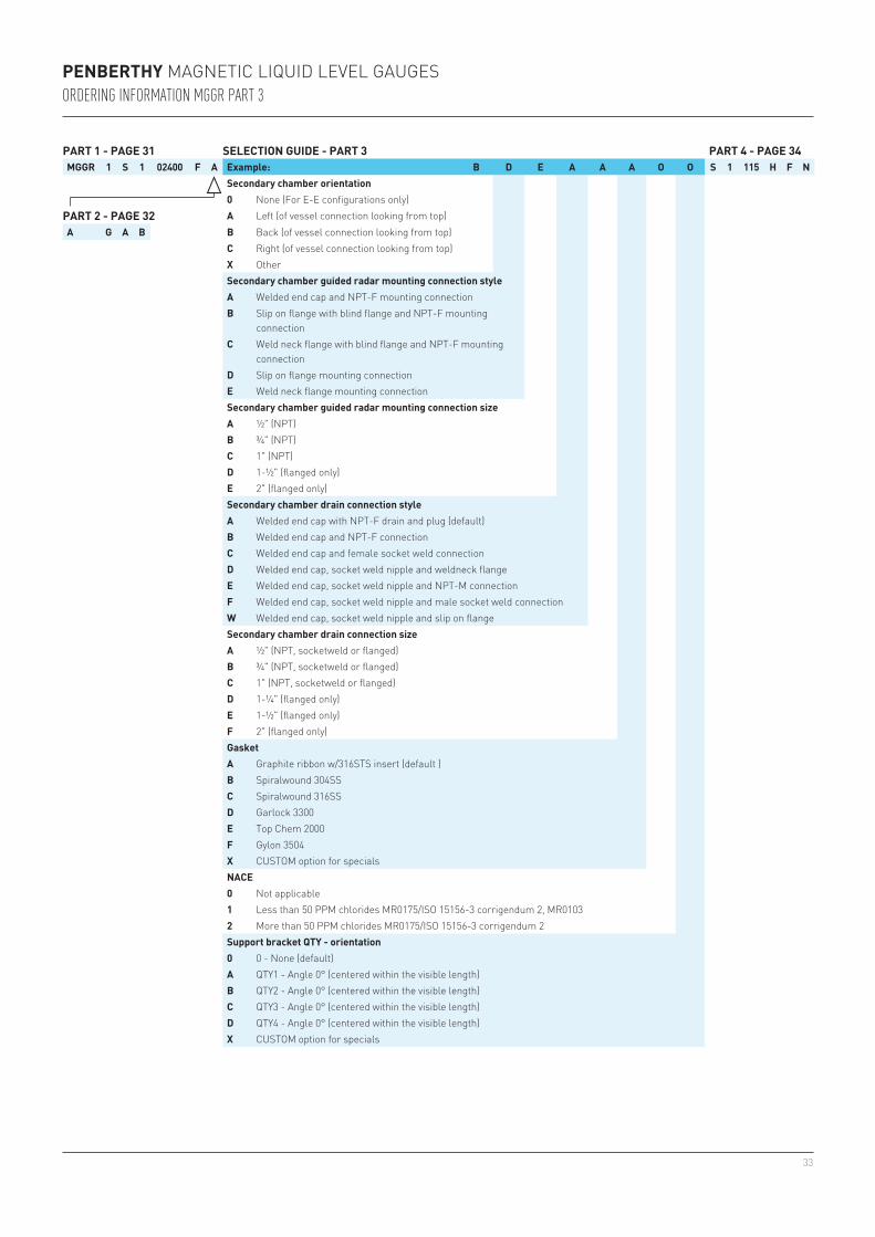
PART 1 - PAGE 31 SELECTION GUIDE - PART 3 PART 4 - PAGE 34MGGR 1 S 1 02400 F A Example: B D E A A A O O S 1 115 H F N
Secondary chamber orientation0 None (For E-E configurations only)
PART 2 - PAGE 32 A Left (of vessel connection looking from top)A G A B B Back (of vessel connection looking from top)
C Right (of vessel connection looking from top)X OtherSecondary chamber guided radar mounting connection styleA Welded end cap and NPT-F mounting connectionB Slip on flange with blind flange and NPT-F mounting
connectionC Weld neck flange with blind flange and NPT-F mounting
connectionD Slip on flange mounting connectionE Weld neck flange mounting connectionSecondary chamber guided radar mounting connection sizeA ½" (NPT) B ¾" (NPT)C 1" (NPT)D 1-½" (flanged only)E 2" (flanged only)Secondary chamber drain connection styleA Welded end cap with NPT-F drain and plug (default)B Welded end cap and NPT-F connectionC Welded end cap and female socket weld connectionD Welded end cap, socket weld nipple and weldneck flangeE Welded end cap, socket weld nipple and NPT-M connectionF Welded end cap, socket weld nipple and male socket weld connectionW Welded end cap, socket weld nipple and slip on flangeSecondary chamber drain connection sizeA ½" (NPT, socketweld or flanged) B ¾" (NPT, socketweld or flanged)C 1" (NPT, socketweld or flanged)D 1-¼" (flanged only)E 1-½" (flanged only)F 2" (flanged only)GasketA Graphite ribbon w/316STS insert (default )B Spiralwound 304SSC Spiralwound 316SSD Garlock 3300E Top Chem 2000F Gylon 3504X CUSTOM option for specialsNACE0 Not applicable1 Less than 50 PPM chlorides MR0175/ISO 15156-3 corrigendum 2, MR01032 More than 50 PPM chlorides MR0175/ISO 15156-3 corrigendum 2Support bracket QTY - orientation0 0 - None (default)A QTY1 - Angle 0° (centered within the visible length)B QTY2 - Angle 0° (centered within the visible length)C QTY3 - Angle 0° (centered within the visible length)D QTY4 - Angle 0° (centered within the visible length)X CUSTOM option for specials
PENBERTHY MAGNETIC LIQUID LEVEL GAUGESORDERING INFORMATION MGGR PART 3
34
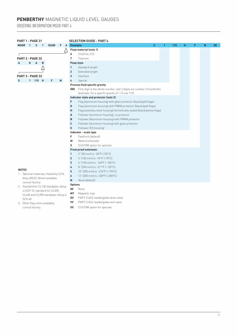
PART 1 - PAGE 31 SELECTION GUIDE - PART 4MGGR 1 S 1 02400 F A Example: S 1 115 H F N 00
Float material (note 1)S 316/316L STS
PART 2 - PAGE 32 T TitaniumA G A B Float style
1 Standard length2 Extended length
PART 3 - PAGE 33 3 InterfaceS 1 115 H F N 4 Special
Process fluid specific gravity000 First digit is the whole number, last 2 digits are number of hundreths
(example: for a specific gravity of 1.15 use 115)Indicator style and protector (note 3)F Flag (aluminum housing) with glass protector (black/gold flags)G Flag (aluminum housing) with PMMA protector (black/gold flags)H Flag (stainless steel housing) hermetically sealed (black/yellow flags)A Follower (aluminum housing), no protectorB Follower (Aluminum housing) with PMMA protectorC Follower (aluminum housing) with glass protectorS Follower (SS housing)
NOTES1. Optional materials, Hastelloy C276,
Alloy 20Cb3, Monel available, consult factory.
2. Standard for CL150 standpipe rating is SCH 10, standard for CL300, CL600 and CL900 standpipe rating is SCH 40.
3. Other flag colors available, consult factory.
Indicator - scale typeF Feet/inch (default)M Meter/centimeterX CUSTOM option for specialsFrost proof extension1 2" (50 mm) to -30°F (-35°C)2 4" (100 mm) to -94°F (-70°C)3 6" (150 mm) to -148°F (-100°C)4 8" (200 mm) to -211°F (-135°C)5 10" (250 mm) to -274°F (-170°C)6 12" (300 mm) to -328°F (-200°C)N None (default)Options00 NoneMT Magnetic trapDV FNPT 316SS needle/globe drain valveVV FNPT 316SS needle/globe vent valve
XX CUSTOM option for specials
PENBERTHY MAGNETIC LIQUID LEVEL GAUGESORDERING INFORMATION MGGR PART 4
35
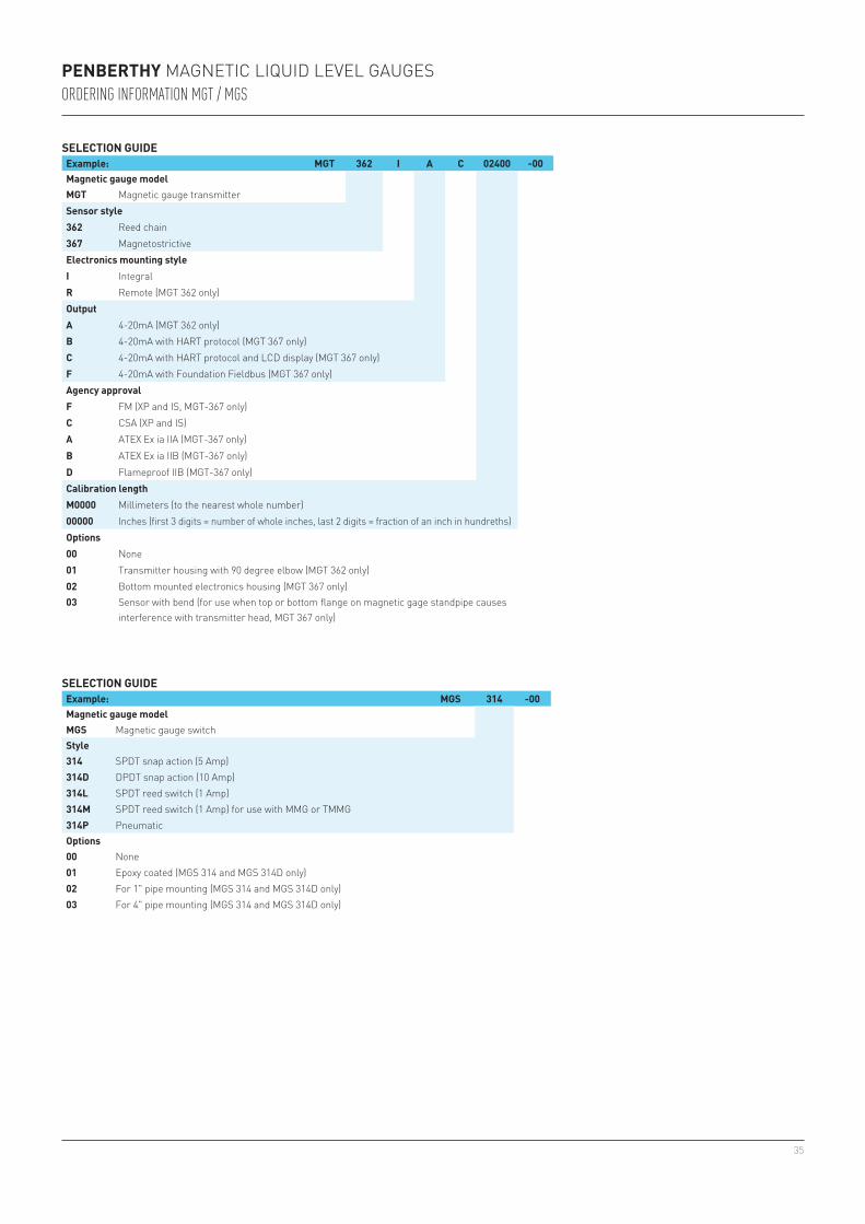
SELECTION GUIDEExample: MGT 362 I A C 02400 -00Magnetic gauge modelMGT Magnetic gauge transmitterSensor style362 Reed chain367 MagnetostrictiveElectronics mounting styleI IntegralR Remote (MGT 362 only)OutputA 4-20mA (MGT 362 only)B 4-20mA with HART protocol (MGT 367 only)C 4-20mA with HART protocol and LCD display (MGT 367 only)F 4-20mA with Foundation Fieldbus (MGT 367 only)Agency approvalF FM (XP and IS, MGT-367 only)C CSA (XP and IS)A ATEX Ex ia IIA (MGT-367 only)B ATEX Ex ia IIB (MGT-367 only)D Flameproof IIB (MGT-367 only)Calibration lengthM0000 Millimeters (to the nearest whole number)00000 Inches (first 3 digits = number of whole inches, last 2 digits = fraction of an inch in hundreths)Options00 None01 Transmitter housing with 90 degree elbow (MGT 362 only)02 Bottom mounted electronics housing (MGT 367 only)03 Sensor with bend (for use when top or bottom flange on magnetic gage standpipe causes
interference with transmitter head, MGT 367 only)
SELECTION GUIDEExample: MGS 314 -00Magnetic gauge modelMGS Magnetic gauge switchStyle314 SPDT snap action (5 Amp)314D DPDT snap action (10 Amp)314L SPDT reed switch (1 Amp)314M SPDT reed switch (1 Amp) for use with MMG or TMMG314P Pneumatic Options00 None01 Epoxy coated (MGS 314 and MGS 314D only)02 For 1" pipe mounting (MGS 314 and MGS 314D only)03 For 4" pipe mounting (MGS 314 and MGS 314D only)
PENBERTHY MAGNETIC LIQUID LEVEL GAUGESORDERING INFORMATION MGT / MGS

36