Embed Size (px)
Citation preview

Pencil:
A Petri Net Specification Language for Java
Christopher Conway Cheng-Hong Li Megan Pengelly
3 December 2002
Contents
1 An Introduction to Pencil 3
1.1 Background . . . . . . . . . . . . . . . . . . . . . . . . . . . . . . . . . . . . . . . . . . . . . . 31.2 Related Work . . . . . . . . . . . . . . . . . . . . . . . . . . . . . . . . . . . . . . . . . . . . . 41.3 Goals of Pencil . . . . . . . . . . . . . . . . . . . . . . . . . . . . . . . . . . . . . . . . . . . . 4
1.3.1 Intuitive . . . . . . . . . . . . . . . . . . . . . . . . . . . . . . . . . . . . . . . . . . . . 41.3.2 Object-Oriented . . . . . . . . . . . . . . . . . . . . . . . . . . . . . . . . . . . . . . . 41.3.3 Portable . . . . . . . . . . . . . . . . . . . . . . . . . . . . . . . . . . . . . . . . . . . . 41.3.4 Powerful . . . . . . . . . . . . . . . . . . . . . . . . . . . . . . . . . . . . . . . . . . . . 51.3.5 Robust . . . . . . . . . . . . . . . . . . . . . . . . . . . . . . . . . . . . . . . . . . . . 5
2 Tutorial 6
2.1 A First Example . . . . . . . . . . . . . . . . . . . . . . . . . . . . . . . . . . . . . . . . . . . 62.2 Compiling and Running Pencil Spec Files . . . . . . . . . . . . . . . . . . . . . . . . . . . . . 72.3 More Examples . . . . . . . . . . . . . . . . . . . . . . . . . . . . . . . . . . . . . . . . . . . . 7
3 Reference Manual 10
3.1 Grammar Notation . . . . . . . . . . . . . . . . . . . . . . . . . . . . . . . . . . . . . . . . . . 103.2 Lexical Conventions . . . . . . . . . . . . . . . . . . . . . . . . . . . . . . . . . . . . . . . . . 10
3.2.1 Line Terminators . . . . . . . . . . . . . . . . . . . . . . . . . . . . . . . . . . . . . . . 103.2.2 Comments . . . . . . . . . . . . . . . . . . . . . . . . . . . . . . . . . . . . . . . . . . . 103.2.3 Whitespace . . . . . . . . . . . . . . . . . . . . . . . . . . . . . . . . . . . . . . . . . . 103.2.4 Tokens . . . . . . . . . . . . . . . . . . . . . . . . . . . . . . . . . . . . . . . . . . . . . 103.2.5 Identifiers . . . . . . . . . . . . . . . . . . . . . . . . . . . . . . . . . . . . . . . . . . . 113.2.6 Keywords . . . . . . . . . . . . . . . . . . . . . . . . . . . . . . . . . . . . . . . . . . . 113.2.7 Constants . . . . . . . . . . . . . . . . . . . . . . . . . . . . . . . . . . . . . . . . . . . 113.2.8 Separators . . . . . . . . . . . . . . . . . . . . . . . . . . . . . . . . . . . . . . . . . . . 113.2.9 Embedded Java Blocks . . . . . . . . . . . . . . . . . . . . . . . . . . . . . . . . . . . . 11
3.3 Petri Net Specifications . . . . . . . . . . . . . . . . . . . . . . . . . . . . . . . . . . . . . . . 123.3.1 Names . . . . . . . . . . . . . . . . . . . . . . . . . . . . . . . . . . . . . . . . . . . . . 123.3.2 Package Declaration . . . . . . . . . . . . . . . . . . . . . . . . . . . . . . . . . . . . . 123.3.3 Net Declaration . . . . . . . . . . . . . . . . . . . . . . . . . . . . . . . . . . . . . . . . 123.3.4 Constant Declarations . . . . . . . . . . . . . . . . . . . . . . . . . . . . . . . . . . . . 133.3.5 Place Declarations . . . . . . . . . . . . . . . . . . . . . . . . . . . . . . . . . . . . . . 133.3.6 Transition Declaration . . . . . . . . . . . . . . . . . . . . . . . . . . . . . . . . . . . . 13
4 Project Plan 15
4.1 Team Responsibilities . . . . . . . . . . . . . . . . . . . . . . . . . . . . . . . . . . . . . . . . 154.2 Project Timeline . . . . . . . . . . . . . . . . . . . . . . . . . . . . . . . . . . . . . . . . . . . 154.3 Software Development Environment . . . . . . . . . . . . . . . . . . . . . . . . . . . . . . . . 154.4 Project Log . . . . . . . . . . . . . . . . . . . . . . . . . . . . . . . . . . . . . . . . . . . . . . 15
1

5 Architectural Design 17
5.1 Architecture . . . . . . . . . . . . . . . . . . . . . . . . . . . . . . . . . . . . . . . . . . . . . . 175.2 The Runtime Environment . . . . . . . . . . . . . . . . . . . . . . . . . . . . . . . . . . . . . 195.3 Error Recovery . . . . . . . . . . . . . . . . . . . . . . . . . . . . . . . . . . . . . . . . . . . . 20
6 Testing Plan 22
6.1 Goals . . . . . . . . . . . . . . . . . . . . . . . . . . . . . . . . . . . . . . . . . . . . . . . . . 226.2 Hypothesis . . . . . . . . . . . . . . . . . . . . . . . . . . . . . . . . . . . . . . . . . . . . . . 226.3 Methods . . . . . . . . . . . . . . . . . . . . . . . . . . . . . . . . . . . . . . . . . . . . . . . . 22
6.3.1 Phase I . . . . . . . . . . . . . . . . . . . . . . . . . . . . . . . . . . . . . . . . . . . . 226.3.2 Phase II . . . . . . . . . . . . . . . . . . . . . . . . . . . . . . . . . . . . . . . . . . . . 226.3.3 Phase III . . . . . . . . . . . . . . . . . . . . . . . . . . . . . . . . . . . . . . . . . . . 23
6.4 Tools . . . . . . . . . . . . . . . . . . . . . . . . . . . . . . . . . . . . . . . . . . . . . . . . . . 236.5 Implementation . . . . . . . . . . . . . . . . . . . . . . . . . . . . . . . . . . . . . . . . . . . . 23
6.5.1 Phase I . . . . . . . . . . . . . . . . . . . . . . . . . . . . . . . . . . . . . . . . . . . . 236.5.2 Phase II . . . . . . . . . . . . . . . . . . . . . . . . . . . . . . . . . . . . . . . . . . . . 236.5.3 Phase III . . . . . . . . . . . . . . . . . . . . . . . . . . . . . . . . . . . . . . . . . . . 24
A Pencil Grammar 25
B Code Style Conventions 27
B.1 Introduction . . . . . . . . . . . . . . . . . . . . . . . . . . . . . . . . . . . . . . . . . . . . . . 27B.2 General Principles . . . . . . . . . . . . . . . . . . . . . . . . . . . . . . . . . . . . . . . . . . 27B.3 Tabs . . . . . . . . . . . . . . . . . . . . . . . . . . . . . . . . . . . . . . . . . . . . . . . . . . 27B.4 Documentation Comments . . . . . . . . . . . . . . . . . . . . . . . . . . . . . . . . . . . . . . 27
2

Chapter 1
An Introduction to Pencil
The Pencil language is designed to help developers quickly prototype, simulate and build their systems usingthe formal language of Petri nets. Using Pencil, it is possible to specify and model a system and to putabstract models directly into action. Pencil compiles Petri net specifications into objects defined in the Javalanguage, allowing Pencil to seamlessly integrate with real-world enterprise applications.
Pencil is designed to be simple, intuitive, flexible, formal, powerful and highly modular. The formalproperties allow theoreticians to leverage the rich literature on Petri nets in modelling and designing systems.The modularity and Java integration allows working programmers to combine verified modules with noadditional work. The simple syntax (similar to Java and C++) and automatic translation mechanism helpreduce implementation errors. Pencil extends the mathematical model of Petri nets so that applicationbehavior can be described simply and economically. This combination of features make Pencil a good bridgebetween modeling and implementation.
1.1 Background
Petri nets are a graphical and mathematical modeling tool which are useful for modeling systems with con-current, asynchronous, distributed or parallel properties. They have been observed to have broad applicationin modeling finite state machines, parallel activities, dataflow computations, communication protocols, sy-chronization control, discrete event systems, and asynchronous circuits [1]. They were introduced by CarlAdam Petri in 1962 [3]. In early 1970’s MIT was very active in the research of Petri nets. Since the late1970’s, European researchers have organized workshops and published conference proceedings on Petri nets[1]. Murata’s IEEE paper [1] and Peterson’s book [2] are good introductions to the subject.
The Petri nets can mathematically be described as follows:Let
�denote the set of nonnegative integers. A Petri net with inhibitor arcs is a 6-tuple PN =
(P, T, F, I, V, m0), where:
• P = {p1, p2, . . . , p|P |} is a set of places, where |P | denotes the cardinality of set P ,
• T = {t1, t2, . . . , t|T |} is a set of transitions, where |T | denotes the cardinality of set T and P ∩ T = ∅,
• F ⊆ (P × T ) ∪ (T × P ),
• I ⊆ (P × T ),
• V is a weight function: F 7→�, and
• m0 is the initial marking P 7→�.
Petri nets can be viewed as bipartite directed multigraphs. The set of nodes is divided into two disjointsets: P and T . An arc in F connects a pair of nodes in P ×T or T ×P . The mapping V assigns non-negativeintegers to arcs. An arc assigned with number k denotes k–parallel arcs between the same pair of nodes.A marking m ∈ (
�∪ 0)n is a mapping from every place p to a non-negative integer. If the number k is
3

assigned to the place p, we say that there are k tokens on place p. The number of tokens on place p undermarking m is represented by m(p). The initial marking m0 is the districution of tokens between the placesof the net before any action is taken. The input place of a transition t , denoted as t−, is a set of places{p | p ∈ P, (p, t) ∈ F}. The output place of a transition t is a set of places defined as {p | p ∈ P, ∃t ∈ T suchthat (t, p) ∈ F}, and is denoted by t+. The functions t−(p) = i is defined as (p, t) ∈ F and V ((p, t)) = i.Similarly t+(p) = i is defined as (t, p) ∈ F and V (t, p) = j.
A transition t is said to be enabled given a marking m iff ∀p ∈ t−, m(p) ≥ t−(p). An enabled transitionis ready to fire. When a transition fires, it removes tokens from its input places and puts tokens in itsoutput places. An enabled transition may or may not fire, and there may be more than one transitionenabled in a given marking, but only one transition can fire at a time. If the current marking of the net ism, t is the fired transition, and m′ is the marking after the firing of t, the relation between m and m′ ism′(p) = m(p) − t−(p) + t+(p), for every p ∈ P .
An inhibitor arc in I is an arc connecting a place and a transition. The connected transition cannotfire if the input place along the inhibitor arc contains at least one token. A transition with inhibitor arcs isenabled iff ∀p ∈ t−, m(p) ≥ t−(p) and every input place along the inhibitor arcs contains no token. Afterthe transition fires, no token is removed through the inhibitor arc. Inhibitor arcs give Petri nets the abilityto test “zero”. This extends the modeling power of Petri nets to the level of Turing machines.
1.2 Related Work
Most of the Petri net simulation tools are focused on graphical user interfaces, simulations, and verifications.These stand-alone applications can be very useful if only system simulations and verifications are required.Very rare applications can aid designers integrating high level models into implementations. The CoOperativeObjects (COO) and its supporting tool SYROCO extend Petri nets’ description ability and translate COOmodels into C++ classes [4]. This full- fledged framework also aims for bridging the gap between theformalism and detailed design.
1.3 Goals of Pencil
Pencil is an intuitive, object-oriented, portable, powerful way to simulate a Petri net while reducing imple-mentation errors and modeling system behavior simulation accurately and efficiently.
1.3.1 Intuitive
The foremost goal in the creation of this language was to make it easy to learn and straightforward toprogram. The user should be left to concentrate on the structure and design of her Petri net, not the syntaxof the modeling language. We created Pencil to be consistent and intuitive, even to users who have limitedprogramming experience.
1.3.2 Object-Oriented
By supporting the concept of objects, each component of the net has its own attributes. By breaking downthe net into its components, we believe that most users will find Pencil to be conceptually intuitive to use.
1.3.3 Portable
The compiler will accept a Pencil specification as an input file and generate Java source code. This sourcecode can be integrated with a larger Java project and compiled with any Java compiler. Because Java isPencil’s target platform, portability is limited only by the availability of a Java Virtual Machine.
4
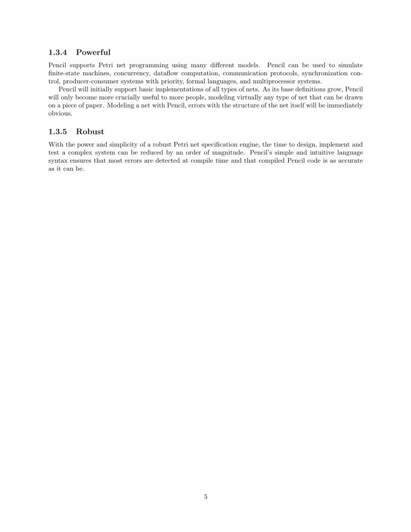
1.3.4 Powerful
Pencil supports Petri net programming using many different models. Pencil can be used to simulatefinite-state machines, concurrency, dataflow computation, communication protocols, synchronization con-trol, producer-consumer systems with priority, formal languages, and multiprocessor systems.
Pencil will initially support basic implementations of all types of nets. As its base definitions grow, Pencilwill only become more crucially useful to more people, modeling virtually any type of net that can be drawnon a piece of paper. Modeling a net with Pencil, errors with the structure of the net itself will be immediatelyobvious.
1.3.5 Robust
With the power and simplicity of a robust Petri net specification engine, the time to design, implement andtest a complex system can be reduced by an order of magnitude. Pencil’s simple and intuitive languagesyntax ensures that most errors are detected at compile time and that compiled Pencil code is as accurateas it can be.
5

Chapter 2
Tutorial
A Pencil Petri net specification is a sequence of place and transition definitions. Input and output arcscan be defined on the places or transitions. Transitions can be associated with Java code to be executedwhen they fire. Pencil was designed to make the translation from a Petri Net diagram to a specification asstraightforward as possible.
2.1 A First Example
. .•
p1 t1 p2
Figure 2.1: A simple Petri Net.
Figure 2.1 shows a very simple Petri Net. There are two places, p1 and p2. There is one transition, t1.There is one token in p1. t1 has one input arc from p1 and one output arc to p2. Because t1’s input place(p1) has a token, we say that t1 is enabled, meaning it is ready to fire. (Arcs may be labelled with a weight.The arcs in Figure 2.1 are unlabelled, meaning they have the default weight of 1. A transition is enabled ifeach of its input places has a number of tokens equal to or greater than the weight of the arc connecting it.)
To represent this simple Petri net in the Pencil language, you might use a specification like the following:
net FirstNet ;
place p1(=1), p2 ;
transition t1 {
in: p1 ;
out: p2 ;
}
FirstNet defines two places and a transition, as in Figure 2.1. The notation p1(=1) means that p1 hasan initial marking of one token (i.e., has one token to start). When run, FirstNet will see that t1 is enabledand fire it, removing one token from p1 and placing one in p2. We haven’t defined any actions for Pencil totake when t1 fires, so there will be no output to the screen.l
We can make our example more interesting by adding embedded Java code to the transition definition:
transition t1 {
in: p1 ;
out: p2 ;
<% System.out.println("Hello, world!") ; %>
}
6

Now the statement System.out.println("Hello, world!") is associated with t1. When t1 fires, thisstatement will be executed, printing the string “Hello, world!” to the standard output.
In both of the specifications above, the transition fires as soon as it is enabled. Sometimes we want atransition to fire only when an event occurs. To do this, we can change the transition property ‘fire’ to‘onCall’, as follows:
transition t1 {
in: p1 ;
out: p2 ;
fire: onCall ;
<% System.out.println("Hello World!") ; %>
}
Now, t1 will not fire until it is requested to do so by a client program. Pencil will add a method calledt1() to the generated Java class. When a Java client calls the method, it will block until t1 is enabled, thenfire the transition and return.
2.2 Compiling and Running Pencil Spec Files
Once you have a simple example of a Petri net that you want to run through Pencil, create a .pen file withyour net declaration, places and transition definitions and then compile it using Pencil. If you have createda net named MyPetriNet in a file name mynet.pen, you would compile it using:
$ java pencil.Main mynet.pen
This will produce a file called MyPetriNet.java that contains java code implementing this Petri net.Compile the java file using javac and then run it using java:
$ javac MyPetriNet.java
$ java MyPetriNet
2.3 More Examples
The more complex a Petri net is, the harder it is to guarantee that it will behave as expected. We’ll look afew more Petri nets in this section, side-by-side with their Pencil specification files, so that you can start tosee how complex systems can be represented in Pencil.
.
.
•• p1
p2
p3
p4
t1
t2
t3
22
2
Figure 2.2: A second Petri net example.
Figure 2.3 shows a more complicated Petri Net example. Notice that several of the arcs are labelled withweights. This Petri Net could be specified in Pencil as follows:
net SecondNet ;
place p1(=2), p2, p3(=1), p4 ;
7

transition t1 {
in: p1(2) ;
out: p2, p3 ;
}
transition t2 {
in: p2, p4(2) ;
out: p1 ;
}
transition t3 {
in: p3 ;
out: p1, p4(2) ;
}
Note the arc definitions of the form p1(2). This means that p1 has a weight of 2 tokens.The Pencil language allows you to define arcs on either transitions or places. This allows the programmer
the flexibility to specify a Petri net in whichever form is most convenient. The same Petri net could also bedefined as follows:
net SecondNetPlaceDef ;
transition t1, t2, t3 ;
place p1(=2) {
in: t3, t2 ;
out: t1(2) ;
}
place p2 {
in: t1 ;
out: t2 ;
}
place p3(=1) {
in: t1 ;
out: t3 ;
}
place p4 {
in: t3(2) ;
out: t2(2) ;
}
We conclude this tutorial with a complete example drawn from the Petri net in Figure 2.3.
net LiveACnet;
place p1(=1), p2, p3, p4 ;
transition t1{
in: p1 ;
out: p2, p4 ;
8

.
.•
p1
p2 p3p4
t1 t2 t3
t4
Figure 2.3: A final Petri net example.
}
transition t2{
in: p3, p2 ;
out: p1 ;
}
transition t3 {
in: p3 ;
out: p1 ;
}
transition t4 {
in: p4 ;
out: p3 ;
}
9
Chapter 3
Reference Manual
3.1 Grammar Notation
Grammar symbols are defined as they are introduced in this document. Regular expression notation hasbeen used to make the productions more perspicuous. Symbols in italics are nonterminals. Quoted symbolsare terminals. ‘s?’ denotes the symbol s is optional. ‘s∗’ denotes the symbol s may be occur zero or moretimes. ‘s+’ denotes the symbol s may occur one or more times. ‘(s|t)’ denotes a choice between the symbolsequences s and t. Parentheses are also used to group symbols with respect to ‘?’, ‘∗’ and ‘+’.
3.2 Lexical Conventions
A program consists of one or more Petri net specifications stored in files. Programs are written using theUnicode character set. The precise version of Unicode used will be determined by the Java Virtual Machineused to run the Pencil compiler. For more information, refer to your Java Developer’s Kit documentation.
3.2.1 Line Terminators
The sequence of input characters is divided into lines by line terminators. Lines are terminated by the ASCIIcharacters CR (“carriage return”), LF (“linefeed”), or CR LF. The CR LF combination is counted as one lineterminator, not two.
3.2.2 Comments
Both C- and C++-style comments are supported. A C-style comment begins with the characters /* andends with the characters */. Any sequence of characters may appear inside of a C-style comment except thestring ‘*/’. C-style comments do not nest. A C++-style comment begins with the characters // and endswith a line terminator.
/* and */ have no special meaning inside comments beginning with //. // has no special meaning insidecomments beginning with /*.
3.2.3 Whitespace
Whitespace is defined as the ASCII space, horizontal tab and form feed characters, as well as line terminatorsand comments.
3.2.4 Tokens
There are five classes of tokens: identifiers, keywords, constants, separators and embedded Java blocks.Whitespace is ignored except as a token separator. Whitespace is sometimes required to separate adjacent
10

tokens that might otherwise be combined into one token (i.e., identifiers, keywords and constants).Token formation is greedy: the input is searched for the longest string of characters that could constitute
a token.
3.2.5 Identifiers
An identifier is a sequence of letters or digits, the first of which must be a letter. There is no limit on thelength of an identifier.
Two identifiers are the same if they have the same Unicode character for every letter and digit. Identifiersthat have the same external appearance may not by identical. For example, the Latin capital letter ’A’ andthe Greek capital letter ‘A’ (“Alpha”) are different Unicode characters that have the same appearance whendisplayed.
Identifier → letter (letter | digit)∗
3.2.6 Keywords
The following identifiers are reserved for use as keywords, and may not be used otherwise:
boolean
byte
char
const
double
fire
float
immediate
in
int
long
net
onCall
out
package
place
public
ret
short
transition
3.2.7 Constants
Constants are a sequence of ASCII digits representing an integer literal. Constants are unsigned, and theinteger represented must be within the range of the Java primitive type int.
Constant → digit+
3.2.8 Separators
The following ASCII characters are separators:
{ } [ ] : ; , .
3.2.9 Embedded Java Blocks
Embedded Java blocks begin with the character sequence <% and end with the character sequence %>. Theembedded code will be inserted into the generated class file without alteration. The type of code allowedwithin a Java block depends on the location of the block within the specification, but no embedded Javacode may contain the string ‘%>’. The compiler may inspect the Java code and issue errors or warnings, butit is not required to do so.
JavaBlock → ‘<%’ JavaCode ‘%>’
11

3.3 Petri Net Specifications
A Pencil Petri net specification is a file that contains a net declaration followed by any number of place andtransition declarations with an optional concluding Java block. A specification is compiled into a Java classthat extends Thread. Calling the method start() on the generated class will begin execution of the PetriNet.
PencilSpecification → PackageDeclaration?
NetDeclaration
(P laceDeclaration | TransitionDeclaration)∗
3.3.1 Names
A name is bound by a declaration and is available at any point in the specification that follows the declaration.A name must be unique within the specification.
3.3.2 Package Declaration
A specification may begin with an optional package declaration. A package declaration takes the same formas a Java package declaration and has the same semantics for the generated code. A package declarationmust be the first declaration in the file.
PackageDeclaration → package QualifiedIdentifier ‘;’
QualifiedIdentifer → Identifier (‘.’ Identifier)∗
3.3.3 Net Declaration
A net declaration gives a name to the Petri net specified and defines its parameters. The net declaration mustappear before any other non-package declaration. There may only be one net declaration in a specification.The declaration may begin with the keywork public. This will be used as the access modifier for thegenerated class and has the same meaning as it would if applied to a Java class. The declaration may takeany number of parameters of any valid Java type.
NetDeclaration → ‘public’? ‘net’ Identifier NetParameters? ‘;’
NetParameters → ‘(’ NetParameter (‘,’ NetParameter) ∗ ‘)’
NetParameter → JavaType Identifier
JavaType → boolean
| byte
| char
| double
| float
| int
| long
| QualifiedIdentifier
| JavaType (‘[]’)∗
12
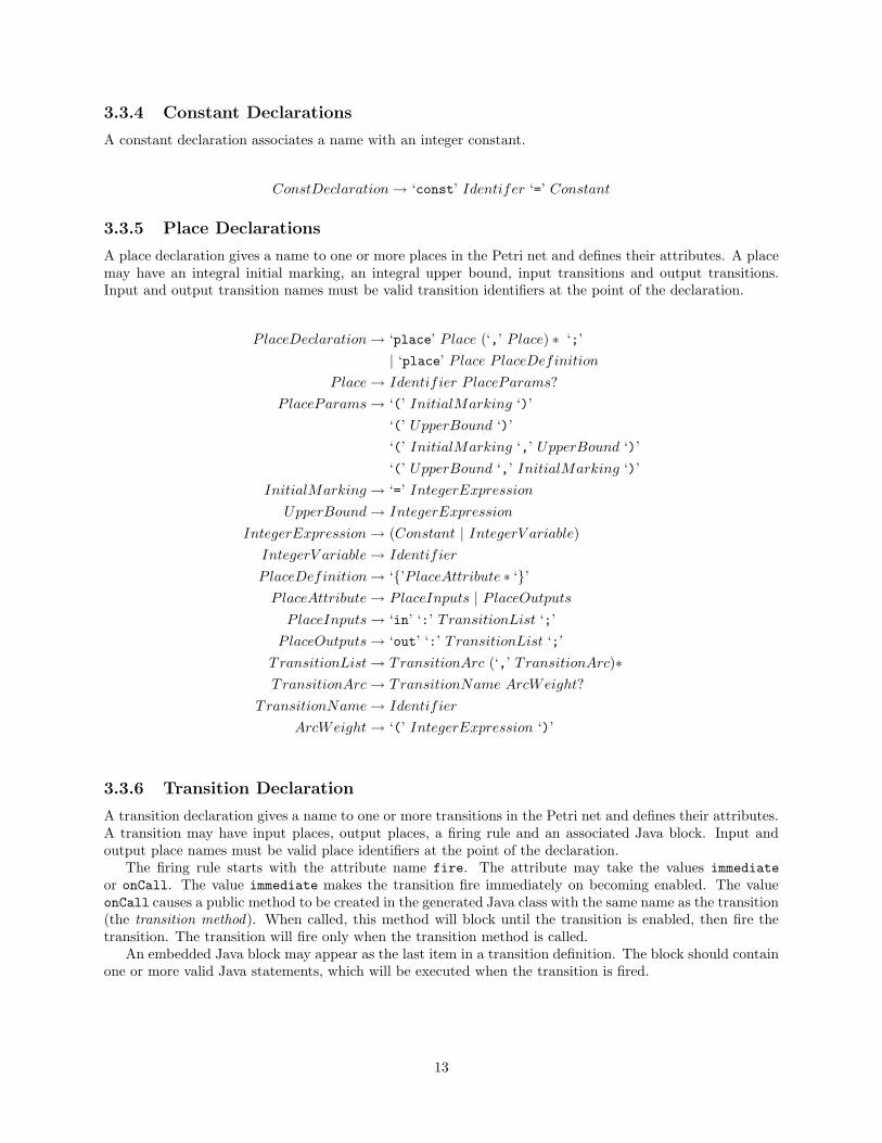
3.3.4 Constant Declarations
A constant declaration associates a name with an integer constant.
ConstDeclaration → ‘const’ Identifer ‘=’ Constant
3.3.5 Place Declarations
A place declaration gives a name to one or more places in the Petri net and defines their attributes. A placemay have an integral initial marking, an integral upper bound, input transitions and output transitions.Input and output transition names must be valid transition identifiers at the point of the declaration.
P laceDeclaration → ‘place’ P lace (‘,’ P lace) ∗ ‘;’
| ‘place’ P lace P laceDefinition
P lace → Identifier P laceParams?
P laceParams → ‘(’ InitialMarking ‘)’
‘(’ UpperBound ‘)’
‘(’ InitialMarking ‘,’ UpperBound ‘)’
‘(’ UpperBound ‘,’ InitialMarking ‘)’
InitialMarking → ‘=’ IntegerExpression
UpperBound → IntegerExpression
IntegerExpression → (Constant | IntegerV ariable)
IntegerV ariable → Identifier
P laceDefinition → ‘{’P laceAttribute ∗ ‘}’
P laceAttribute → P laceInputs | P laceOutputs
P laceInputs → ‘in’ ‘:’ TransitionList ‘;’
P laceOutputs → ‘out’ ‘:’ TransitionList ‘;’
TransitionList → TransitionArc (‘,’ TransitionArc)∗
TransitionArc → TransitionName ArcWeight?
TransitionName → Identifier
ArcWeight → ‘(’ IntegerExpression ‘)’
3.3.6 Transition Declaration
A transition declaration gives a name to one or more transitions in the Petri net and defines their attributes.A transition may have input places, output places, a firing rule and an associated Java block. Input andoutput place names must be valid place identifiers at the point of the declaration.
The firing rule starts with the attribute name fire. The attribute may take the values immediate
or onCall. The value immediate makes the transition fire immediately on becoming enabled. The valueonCall causes a public method to be created in the generated Java class with the same name as the transition(the transition method). When called, this method will block until the transition is enabled, then fire thetransition. The transition will fire only when the transition method is called.
An embedded Java block may appear as the last item in a transition definition. The block should containone or more valid Java statements, which will be executed when the transition is fired.
13
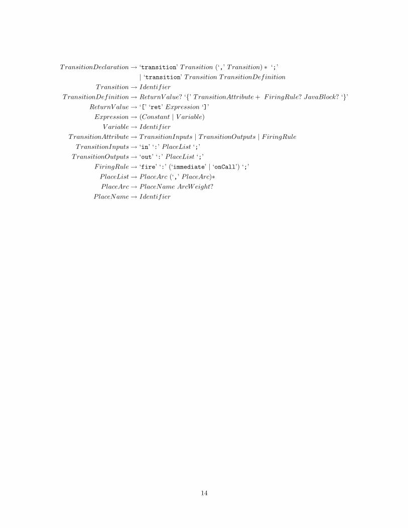
TransitionDeclaration → ‘transition’ Transition (‘,’ Transition) ∗ ‘;’
| ‘transition’ Transition TransitionDefinition
Transition → Identifier
T ransitionDefinition → ReturnV alue? ‘{’ TransitionAttribute + FiringRule? JavaBlock? ‘}’
ReturnV alue → ‘[’ ‘ret’ Expression ‘]’
Expression → (Constant | V ariable)
V ariable → Identifier
T ransitionAttribute → TransitionInputs | TransitionOutputs | FiringRule
TransitionInputs → ‘in’ ‘:’ P laceList ‘;’
TransitionOutputs → ‘out’ ‘:’ P laceList ‘;’
FiringRule → ‘fire’ ‘:’ (‘immediate’ | ‘onCall’) ‘;’
P laceList → P laceArc (‘,’ P laceArc)∗
P laceArc → P laceName ArcWeight?
P laceName → Identifier
14
Chapter 4
Project Plan
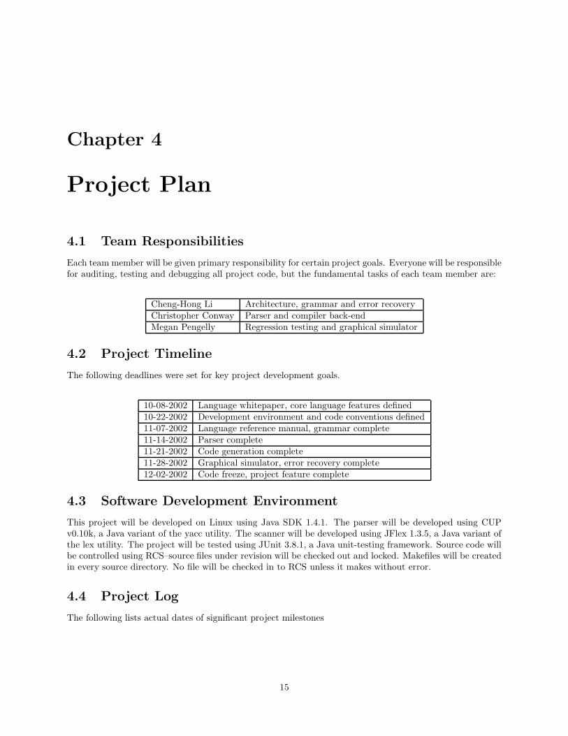
4.1 Team Responsibilities
Each team member will be given primary responsibility for certain project goals. Everyone will be responsiblefor auditing, testing and debugging all project code, but the fundamental tasks of each team member are:
Cheng-Hong Li Architecture, grammar and error recoveryChristopher Conway Parser and compiler back-endMegan Pengelly Regression testing and graphical simulator
4.2 Project Timeline
The following deadlines were set for key project development goals.
10-08-2002 Language whitepaper, core language features defined10-22-2002 Development environment and code conventions defined11-07-2002 Language reference manual, grammar complete11-14-2002 Parser complete11-21-2002 Code generation complete11-28-2002 Graphical simulator, error recovery complete12-02-2002 Code freeze, project feature complete
4.3 Software Development Environment
This project will be developed on Linux using Java SDK 1.4.1. The parser will be developed using CUPv0.10k, a Java variant of the yacc utility. The scanner will be developed using JFlex 1.3.5, a Java variant ofthe lex utility. The project will be tested using JUnit 3.8.1, a Java unit-testing framework. Source code willbe controlled using RCS–source files under revision will be checked out and locked. Makefiles will be createdin every source directory. No file will be checked in to RCS unless it makes without error.
4.4 Project Log
The following lists actual dates of significant project milestones
15

10-01-2002 Project initiated10-08-2002 Language whitepaper complete10-09-2002 Code conventions, first draft10-27-2002 Development environment configured and online10-27-2002 Runtime prototype10-29-2002 Grammar, first draft11-07-2002 Language tutorial, first draft11-07-2002 Language reference manual, first draft11-10-2002 Testing Phase I begins11-11-2002 Code conventions, final draft11-13-2002 Parser and lexer, first working version11-14-2002 Project architecture document complete11-15-2002 Compiler back-end, first working version11-17-2002 Testing Phase II begins11-20-2002 Work on graphical simulator begins11-28-2002 Error recovery complete11-29-2002 Parser and compiler back-end, final versions12-01-2002 Graphical simulator, first version12-03-2002 Text simulator, first version
16

Chapter 5
Architectural Design
5.1 Architecture
The Pencil compiler consists of several major blocks which are common in compiler designs: lexer, parser,symbol table, error handler, the runtime environment, and the code generator. The relationship betweenthese components is demonstrated in Figure 5.1. The code generator is not explicitly shown; but with theparser these two components are implemented using a Director and Builder design pattern. The input to thecompiler are Pencil specification files (which have, by convention, the suffix .pen) and the final output fromthe compiler is translated Java code. The compiler takes one pen file once a time, and translates it to Java.The lexer is implemented in JFlex, a version of lex for Java. The parser is generated by CUP, a version ofyacc for Java. The error handler is deals with error recovery when syntax errors are encountered. It informsthe code generator not to generate the final output whenever a syntax error is found, and prompts the userwith an appropriate error message. The runtime system is a set of predefined classes that are inheritedby the generated Java classes. The runtime classes provide the basic computation necessary for Petri netsimulation and execution. Between the parser and the code generator there is a clear interface making thesetwo components highly modular. The Builder pattern allows the change of front-end and back-end designnot to affect the other part of the design if the interface between them is followed.
Lexer Parser(Director)
code generator(NetBuilder)
Symbol Table Error Handler
.pen files .java files
Figure 5.1: The block diagram of PENCIL compiler.
The entry point of the compiler is the class pencil.Main. The main() method parses the commandline argument, and initializes the parser to begin processing the Pencil source file. The interface betweenthe lexer and the parser is the lexer’s next token() method. The parser’s task is the “director” of thecode generator, which is the “builder” of the target code. Semantic actions on parser productions invoke aset of builder method, constructing an abstract Petri net representation from the source code. If a syntaxerror occurs, the parser invokes the error handler (SynErrHandler). The error handler prints an approriateerror message, and also informs the builder that a syntax error has occured. When parsing is finished. thebuild() method of the Builder class is invoked, and the target code is generated.
The Builder pattern most suits a compiler with different targets. The separation of a Director and aBuilder not only allows the creation of different targets with the same front-end components (the parser,lexer, error handler, and symbol table), but also minimizes the effort to improve both the front–end andthe back–end, and add on more language features. The parser is the Director, and it directs the concreteinstances of NetBuilder to build the target, with a sequence of calls. The Java interface NetBuilder defines
17

the interface between the parser and the concrete builders. A Builder class implements this interface andinterprets the sequence of calls from the Director as instructions for building a Petri net class file. Thediagram 5.2 demonstrates the relationship between the parser (Director) and the NetBuilder (Builder).
Parser NetBuilder
+startPlace(name:String): void+endPlace(): void+setMarking(n:int): void+setBound(): void+build(): void+startTransition(): void+setReturn(): void+setFire(): void+setJava(): void+addTransition(): void+endTransition(): void+setPackage(): void+setNet(): void+addParam(): void+addConstraint()
DefaultBuilder DebugBuilder AppletBuilder SimBuilder
Stand-alone application Text SimulatorGUI Simulator
Figure 5.2: The class diagram of director/builder design pattern.
The pencil.Main() instantiates a concrete Builder according to the command line arguments. Thereare implementations of the NetBuilder interface for generating stand-alone Java code, or Petri net simulators(both graphical and text-mode), depending on the user’s preference. The following code fragment setups anappropriate builder and passes it to the director:
Parser p = new Parser(new Lexer(in)) ;
// ...
NetBuilder b = null ;
if( debug ) {
b = new DebugBuilder() ;
} else if (textSim){
b = new SimBuilder();
} else{
b = new DefaultBuilder() ;
}
p.setBuilder(b) ;
The interface between the parser and the NetBuilder defines an abstract model of Petri nets. Thecapture of the abstract model of Petri nets is crucial both to the Director and the Builder. Languageextensions and improved back-end components can be introduced without breaking the Director-Builderinterface. The interface consists mainly of methods to inform the Builder of place definitions, transitiondefinitions, transition firing types and arcs between places and transitions. More specifically, the followingmethods are used to set the place definitions:
public void startPlace(String name) ;
public void setMarking(String m) ;
public void setBound(int b) ;
public void setBound(String b) ;
public void endPlace() ;
The startPlace() is called when the parser finds the beginning of a place definition in the source code.The parser then communicates the initial marking and the upper-bound (on the number of tokens this place
18
can have most) information by calling setMarking and setBound. Finally the endPlace() method is usedto signal the end of a place definition.
The transition-related methods are defined in a similar way. They are:
public void startTransition(String name) ;
public void addTransition(String name) ;
public void setReturn(int r) ;
// ....
public void setFire(Integer f) ;
public void setJava(String code) ;
public void endTransition() ;
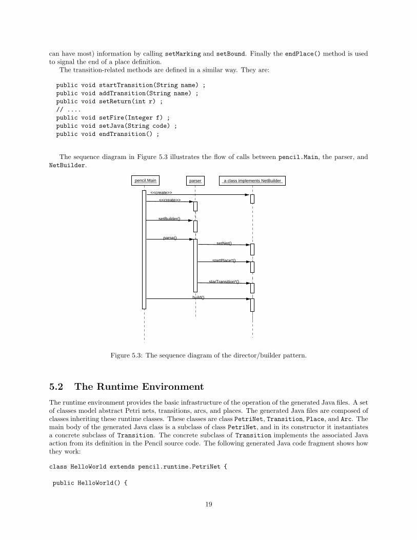
The sequence diagram in Figure 5.3 illustrates the flow of calls between pencil.Main, the parser, andNetBuilder.
pencil.Main parser a class implements NetBuilder
<<create>>
<<create>>
setBuilder()
parse()setNet()
startPlace*()
starTransition*()
build()
Figure 5.3: The sequence diagram of the director/builder pattern.
5.2 The Runtime Environment
The runtime environment provides the basic infrastructure of the operation of the generated Java files. A setof classes model abstract Petri nets, transitions, arcs, and places. The generated Java files are composed ofclasses inheriting these runtime classes. These classes are class PetriNet, Transition, Place, and Arc. Themain body of the generated Java class is a subclass of class PetriNet, and in its constructor it instantiatesa concrete subclass of Transition. The concrete subclass of Transition implements the associated Javaaction from its definition in the Pencil source code. The following generated Java code fragment shows howthey work:
class HelloWorld extends pencil.runtime.PetriNet {
public HelloWorld() {
19

pencil.runtime.Place p2 = new pencil.runtime.Place() ;
add(p2) ;
pencil.runtime.Place p1 = new pencil.runtime.Place(1) ;
add(p1) ;
pencil.runtime.Transition t1 = new pencil.runtime.Transition() {
public Object onFire() {
System.out.println("Hello, world!") ;
return null ;
}
} ;
// ...
5.3 Error Recovery
The error handling and recovery of Pencil adopts two kinds of techniques to recover from parsing errors.One is the error production, and the other one is the panic mode. Error productions are a set of grammarrules that generate predictable incorrect inputs from users. They are very useful for catching common minorsyntax errors. Any reduction of these error productions means some syntax error has been recovered. Thepanic mode is implemented the support of CUP’s special “error’ token. This special token represents anerror construct in the source file, and the parser will re-synchronize the parsing under the condition that asufficient amount (default value is 3) of correct shifts follows the last error input. Panic mode is useful forbigger syntax errors. The use of the “error” tokens requires great care, usually with the help of the generatedparsing table.
The following error production rule tries to capture the missing semicolon error, which is a common errorin the input pen files:
PlaceDecl ::=
PLACE PlaceList SEMI
// ....
/* Error Productions */
// catch missing semicolon.
| PLACE PlaceList:err
{: parser.errHandler.onErrProduction(SynErrHandler.ERR_MISSING_SEMI,
errleft, errright);
parser.synErr = true;
:}
;
The panic mode technique is for other non–predictable parsing errors. The placement of the “error”tokens are not quite straightforward. The following fragment of the production demonstrates the use of the“error” token:
PlaceDecl ::=
PLACE PlaceList SEMI
| PLACE Place PlaceDef
/* Panic Mode */
| PLACE error:err
{: parser.errHandler.onError(SynErrHandler.ERR_PLACE_MISSING_COMMA_SEMI,
errleft, errright);
parser.synErr = true;
20

:}
Here the “error” token represents an incorrect PlaceList construct.
21
Chapter 6
Testing Plan
6.1 Goals
No test plan can aspire to catch every bug in a program. It is not the goal of this project to test everypossible input to the Pencil compiler. Rather, these tests are designed to lay out a systematic approach tofinding inconsistencies in the way data is treated throughout the development cycle. With careful choice ofunit tests, regression tests, white box and black box tests, the development process can evolve smoothly. Thegoal for the tests deployed against the Pencil code is to test smartly–to write enough tests to test thoroughly,but not so many that time is wasted on insignificant coding–and to run these tests at least daily.
6.2 Hypothesis
Through the use of a variety of well-planned tests, the stability of Pencil code after any modification can beproven by running a single command. This will make for easy code transitions and confident developers.
6.3 Methods
The Pencil group seeks to run tests in parallel with each of three design phases. The tests are cumulative,so that each phase will integrate the tests in all phases previous to it with its tests.
6.3.1 Phase I
Phase I of the testing process will correlate with the initial development phase, where the compiler doesnot work from beginning to end, but the essential components are being built and then gradually linkedtogether.
For this phase, we will use white box testing, so called for its detailed examination of each Java classthat is written. We will test each method in each class to ensure that they perform as expected.
6.3.2 Phase II
Phase II of the testing process will correlate with the finessing phase of development. At this point, all themajor classes have been written and pieced together in their final arrangement.
Tests for this phase will be less minute. We want to ensure that all the blocks of code are correctlyinteracting. Does the compiler behave as expected on known inputs?
This is the phase where regression tests become important. As inconsistencies are discovered and correctedthroughout the code, it is imperative that the flow of data is not affected. With one person modifying anotherperson’s code, it is easy to inadvertently break functionality.
Further, as our compiler begins to accept more complete grammars, we do not want to lose functionalityon the initial grammars that were parsed correctly.
22

6.3.3 Phase III
Phase III is the final testing phase, entered when development is finished. By this point, all of the white boxtests and regression tests have been passed and the code is ready for production.
Installation tests will be performed to ensure that the users can install the compiler with minimal difficulty.Black box tests will be performed on large Petri nets gathered from real-world examples, to ensure that thecompiler performs as expected for varied useful inputs. If necessary, the compiler will be modified as a resultof these tests.
6.4 Tools
JUnit will be used to structure the Phase I and II tests performed against the Pencil compiler. Perl andshell scripts will be used as necessary.
6.5 Implementation
6.5.1 Phase I
Phase I seeks to test each method in each class to ensure that it performs as expected. It will not test get()and set() methods except where deemed necessary.
Here is a brief overview of the Pencil classes and the structure that they will fit into:
1. Syntax analysis - Pencil uses the JFlex Lexer and the CUP parser to generate syntax analysis classesfor its code. To test the parser and lexer generated by this code, we will write a test method thatsubmits a variety of grammars to the parser as a regression test. By running correct and incorrectPencil spec files through the compiler, we will seek to keep parsing consistent through the developmentprocess. As more functionality is added, more Pencil spec files will be written and added to this test.
2. Director/Builder - The director takes the Syntax Tree created by the parser and called Builder methodson it. A test method will be created to perform regression tests on each of the Director and Buildermethods.
There are many small object classes written for the Director and the Builder. A series of small testswill be written to test most of these classes as well.
3. Runtime - The outputted code format. Because we are outputting to Java files, it is important thatthere are no bugs in our runtime code either. A series of test methods will ensure that the Javaframework works under different Petri Net inputs.
In order to complete Phase I, a list of each class and its methods must be compiled. The methods mustbe examined for expected behavior, and test code must be produced to ensure that expected behavior holdstrue. The tests will be tied together using JUnit and run at least once daily.
6.5.2 Phase II
Given a working compiler, does an input .pen file produce expected Java code? Does it do so every day, aschanges are performed? For this phase, test methods must be written to test all aspects of the grammar.Care must be taken to overcome the developer’s bias and test unexpected input. Equally important is thatinvalid input is always rejected, regardless of how advanced the error handling implementation is in the code.
In this phase, we begin to write tests that test the flow of data between classes.
23
6.5.3 Phase III
Because time ran short in the developement process, most of the time at the end of the project was spentwriting documentation and last-minute code changes. This means that the final testing phase became oneof trial and error. The developers made changes and tested them in the most logical fashion. This is notdesirable because each programmer has his or her own bias as to how the code should perform, and isprogramming towards that goal. Independent testing is the only way to ensure reliable code. Given anotherweek, this independent testing of installation on different platforms, and of pencil spec files written by otherscientists would have guaranteed that the code was resiliant.
24
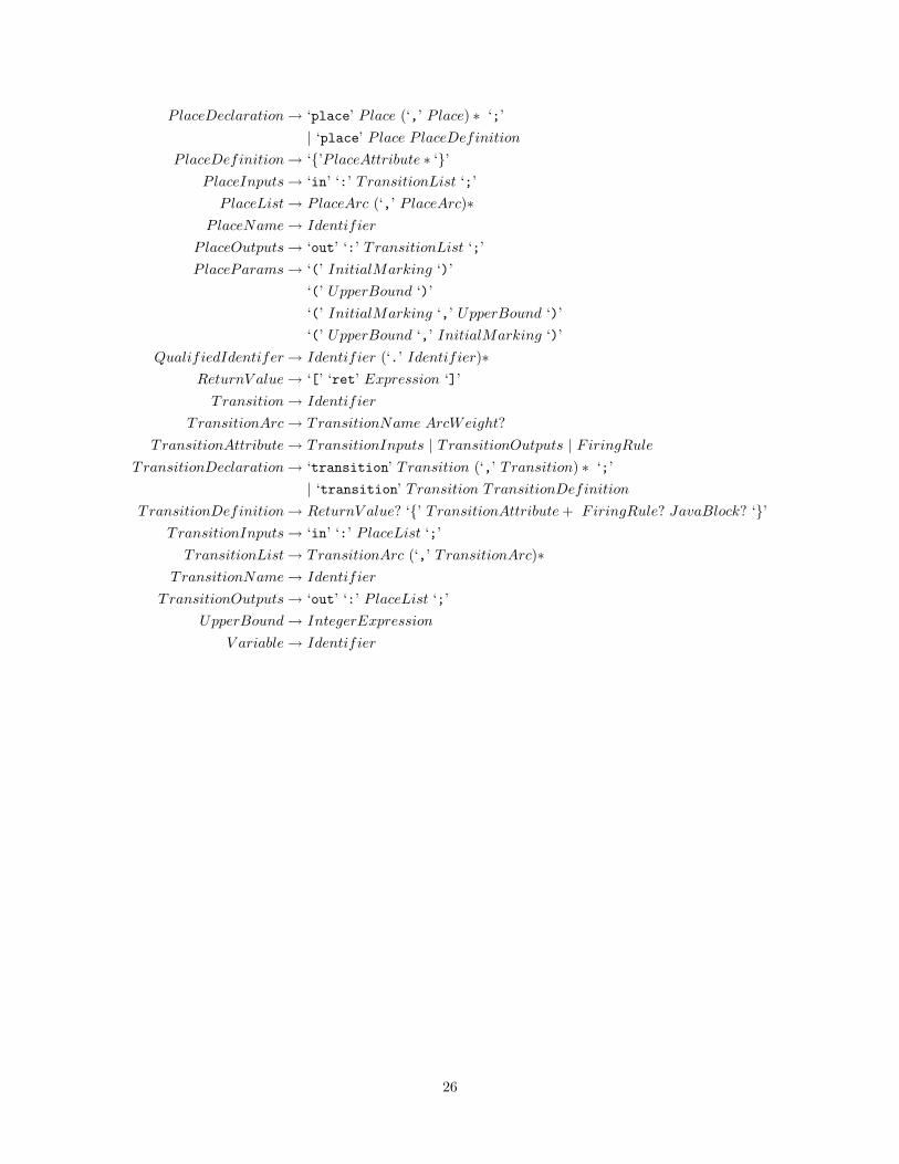
Appendix A
Pencil Grammar
The following lists all of the grammar productions described in Sections 3.2 and 3.3. The start productionis PencilSpecification.
ArcWeight → ‘(’ IntegerExpression ‘)’
Constant → digit+
ConstDeclaration → ‘const’ Identifer Constant
Expression → (Constant | V ariable)
FiringRule → ‘fire’ ‘:’ (‘immediate’ | ‘onCall’) ‘;’
InitialMarking → ‘=’ IntegerExpression
IntegerExpression → (Constant | IntegerV ariable)
IntegerV ariable → Identifier
JavaBlock → ‘<%’ JavaCode ‘%>’
JavaType → boolean
| byte
| char
| double
| float
| int
| long
| QualifiedIdentifier
| JavaType (‘[]’)∗
NetDeclaration → ‘public’? ‘net’ Identifier NetParameters? ‘;’
NetParameter → JavaType Identifier
NetParameters → ‘(’ NetParameter (‘,’ NetParameter) ∗ ‘)’
PackageDeclaration → package QualifiedIdentifier ‘;’
PencilSpecification → PackageDeclaration?
NetDeclaration
(P laceDeclaration | TransitionDeclaration)∗
P lace → Identifier P laceParams?
P laceArc → P laceName ArcWeight?
P laceAttribute → P laceInputs | P laceOutputs
25
P laceDeclaration → ‘place’ P lace (‘,’ P lace) ∗ ‘;’
| ‘place’ P lace P laceDefinition
P laceDefinition → ‘{’P laceAttribute ∗ ‘}’
P laceInputs → ‘in’ ‘:’ TransitionList ‘;’
P laceList → P laceArc (‘,’ P laceArc)∗
P laceName → Identifier
P laceOutputs → ‘out’ ‘:’ TransitionList ‘;’
P laceParams → ‘(’ InitialMarking ‘)’
‘(’ UpperBound ‘)’
‘(’ InitialMarking ‘,’ UpperBound ‘)’
‘(’ UpperBound ‘,’ InitialMarking ‘)’
QualifiedIdentifer → Identifier (‘.’ Identifier)∗
ReturnV alue → ‘[’ ‘ret’ Expression ‘]’
Transition → Identifier
T ransitionArc → TransitionName ArcWeight?
TransitionAttribute → TransitionInputs | TransitionOutputs | FiringRule
TransitionDeclaration → ‘transition’ Transition (‘,’ Transition) ∗ ‘;’
| ‘transition’ Transition TransitionDefinition
TransitionDefinition → ReturnV alue? ‘{’ TransitionAttribute + FiringRule? JavaBlock? ‘}’
TransitionInputs → ‘in’ ‘:’ P laceList ‘;’
TransitionList → TransitionArc (‘,’ TransitionArc)∗
TransitionName → Identifier
T ransitionOutputs → ‘out’ ‘:’ P laceList ‘;’
UpperBound → IntegerExpression
V ariable → Identifier
26

Appendix B
Code Style Conventions
B.1 Introduction
The purpose of this document is to provide basic standards for collaborative code development. Programmerscan be very sensitive about where they put their curly braces and semi-colons; it is not the goal of thisdocument to put any team member in a straight-jacket with respect to his or her idioms and idiosyncrasies.The guidelines contained herein reflect core best practices in pursuit of making one’s code perspicuous andmaintainable. Team members should try to follow these guidelines as much as possible in their work.
B.2 General Principles
Code should be easy to read and sensibly laid out. Blocks should be indented a consistent width. Variablesshould have names that clearly indicate their purpose. Non-trivial blocks of code should be accompanied byexplanatory comments. Java code should follow the accepted Java conventions1.
B.3 Tabs
Code files should not contain hard tab characters. A file with hard tabs may appear fine in your text editorand appear as a convoluted mess in someone else’s. This is because editor’s are free to define tab stopsas they please. All tabs should be converted to spaces when a file is saved. To do this in emacs, use thecommand ‘(setq indent-tabs-mode nil)’. In vim, use the command ‘set expandtab’. If you do not useemacs or vim, you should check your software documentation, then reconsider your choice of editor.
B.4 Documentation Comments
Every public method and field of a Java class should be documented with a Javadoc comment2. Commentson a method should describe its parameters, its return value and the exceptions it throws. The commentshould discuss invalid parameter values, whether the method might return null and when an exception mightbe thrown. Pre-conditions, post-conditions and method side effects should also be noted.
1See Code Conventions for the Java Programming Language, http://java.sun.com/docs/codeconv/html/CodeConvTOC.doc.html.2See How to Write Doc Comments for the Javadoc Tool, http://java.sun.com/j2se/javadoc/writingdoccomments/index.html.
27

Bibliography
[1] Tadao Murata. Petri nets: Properties, analysis and applications. Proceedings of the IEEE, 77(4):541–580,April 1989.
[2] James L. Peterson. Petri Net Theory and the Modeling of Systems. Prentice–Hall, Englewood Cliffs,N.J., 1981.
[3] Carl Adam Petri. Kommunikation mit Automaten. PhD thesis, Bonn: Institut fuer InstrumentelleMathematik, 1962.
[4] C. Sibertin-Blanc. CoOperative Objects: Principles, Use and Implementation. 1998.
28