Embed Size (px)
Citation preview
PERCEPTION FOR ROBOTIC AMBIENT
ASSISTED LIVING SERVICES
CLÁUDIA MARQUES PINTO TONELO DISSERTAÇÃO DE MESTRADO APRESENTADA À FACULDADE DE ENGENHARIA DA UNIVERSIDADE DO PORTO EM ENGENHARIA BIOMÉDICA
2014 M

ii
iii
Faculdade de Engenharia da Universidade do Porto
Perception for Robotic Ambient Assisted Living Services
Cláudia Marques Pinto Tonelo
Master in Biomedical Engineering
Supervisor: Prof. António Paulo Moreira (PhD) Co-Supervisor: Germano Veiga (PhD)
July, 2014

iv
© Cláudia Marques Pinto Tonelo, 2014
v
Abstract
The use of mobile robots in the homecare area for elderly or handicapped people has
increased over the last years. Therefore, the main objective of this dissertation was to study
the sensing (sensors and algorithms) for people tracking and human-robot interaction (HRI) in
the scope of its integration in a mobile robotic platform for Ambient Assisted Living (AAL).
In this sense, it was integrated a relatively inexpensive device, the Kinect sensor, for
person tracking purposes, in RobVigil, an indoor surveillance robot developed by FEUP/INESC
TEC, in order to create a system adequate for people assistance.
Throughout this dissertation several algorithms were implemented and tested. For person
detection and tracking, the algorithms were divided into face and body detection/tracking.
The face algorithms provided some difficulties when confronted with lighting variations,
besides it required the person to be facing the sensor. On the other hand, the skeleton tracking
demonstrated to be an appropriate algorithm for people tracking, as it could track the person
in diverse cases (bad illumination and joints occlusion) at further distances, with a higher frame
rate.
Subsequently, with this algorithm it was established a potential non-intrusive method for
person following and HRI. Through the results presented it was confirmed that the robot could
follow the person correctly, at a frame rate of 10 fps. In addition, several videos with depth
data were recorded with people doing gestures and falling to assess the HRI module. The results
obtained proved that distances and angles approaches extracted from the skeleton joints were
vi
suitable features for gesture recognition and fall detection. Also, when a fall occurs, a color
image compression and streaming scheme was implemented to send the image to an external
computer, which achieved notable results in the compression.
Thus, the outcome of the developed work allowed a detailed understanding about different
algorithms for face detection and tracking, body detection and tracking, gesture recognition,
fall detection, and image compression and streaming, for robotic AAL services.
vii
Resumo
A utilização de robôs móveis em áreas de apoio domiciliar para pessoas idosas ou com
mobilidade reduzida tem aumentado nos últimos anos. Portanto, o principal objetivo desta
dissertação foi fazer um estudo dos sensores e algoritmos para deteção de pessoas e interação
humano-robô (HRI), no âmbito da sua integração numa plataforma robótica móvel para Ambient
Assisted Living (AAL).
Neste sentido, foi introduzido um dispositivo relativamente barato, o Kinect, para
possibilitar a deteção de pessoas, no RobVigil, um robô de vigilância desenvolvido pela
FEUP/INESC TEC, de modo a criar um sistema adequado para assistência de pessoas.
Ao longo desta dissertação vários algoritmos foram implementados e testados. Para
deteção e rastreamento de pessoas, os algoritmos foram divididos em deteção/rastreamento
da face e do corpo. Relativamente à face, os algoritmos apresentaram algumas dificuldades
quando confrontados com variações de iluminação, além disso era necessário que a pessoa
estivesse de frente para o sensor. Por outro lado, o skeleton tracking demonstrou ser um
algoritmo apropriado para rastreamento de pessoas, uma vez que conseguiu rastrear a pessoa
em diversos casos (má iluminação e em oclusão de articulações) em distâncias maiores, e com
uma cadência maior.
Subsequentemente, com este algoritmo foi estabelecido um método não-invasivo para
seguimento de pessoas e HRI. Ao longo dos resultados apresentados confirmou-se que o robô
conseguiu seguir a pessoa corretamente, com uma cadência de 10 fps. Além disso, vários vídeos
com imagens de profundidade foram gravados com pessoas a fazer gestos e a cair para ser
possível a avaliação do módulo de HRI. Os resultados obtidos demonstraram que as abordagens
feitas com as distâncias e os ângulos extraídos das articulações do esqueleto foram
características adequadas para o reconhecimento de gestos e deteção de queda. Além disso,
na ocorrência de uma queda, um sistema de compressão e streaming da imagem a cores foi
implementado para assim enviar a imagem para um computador externo, em que a compressão
das imagens adquiriu resultados notáveis.
viii
Assim, os resultados do trabalho desenvolvido permitiu uma compreensão detalhada sobre
diferentes algoritmos para a deteção e rastreamento da face, deteção e rastreamento do
corpo, reconhecimento de gestos, deteção de queda, e compressão e streaming de imagens,
para aplicações robóticas em serviços AAL.
ix
Acknowledgements
Foremost, I would like to express my gratitude to my supervisors, Professor António Paulo
Moreira and Germano Veiga, for their patient guidance, motivation, and immense knowledge.
This dissertation would never have been possible without their help and creative suggestions.
Besides my supervisors, I would like to thank all the members of Robotics and Intelligent
Systems Unit (Robis) of INESC-TEC that directly or indirectly, have contributed to this
dissertation and also for the admirable work environment. Special thanks for Andry Pinto, Filipe
Santos, Héber Sobreira, Luís Rocha, Tatiana Pinho and Marcos Ferreira, for their time, support
and friendship.
Most importantly, to all my family, my parents and brothers for the unconditional support
they have shown and confidence. I would like to express my gratitude to them.
Last but not the least, I would like to thank all my friends who helped me during this year,
and kept me from losing my sanity. And to you Isidro for all the words, patience and
encouragement throughout the hard times of this dissertation.

x
xi
Contents
Abstract .... .................................................................................................v Resumo .................................................................................................... vii Acknowledgements ....................................................................................... ix Contents ... ............................................................................................... .xi List of Figures............................................................................................ xiii List of Tables ............................................................................................xvii Abbreviations ........................................................................................... xviii
Chapter 1 ................................................................................. 1 1.1. Context and Motivation ............................................................................ 1 1.2. Objectives ............................................................................................ 2 1.3. Contributions ........................................................................................ 2 1.4. Structure of the Document ........................................................................ 3
Chapter 2 ................................................................................. 4
2.1. AAL Robots ........................................................................................... 4 2.2. Person Detection & Tracking Sensing ............................................................ 8
2.2.1. Sensors for Service Robots .................................................................. 8 2.2.2. Person Detection/Tracking Algorithms.................................................... 9
2.2.2.1. Face or Head Detection/Tracking ..................................................... 9 2.2.2.2. Body Detection/Tracking .............................................................. 12
2.3. Gesture Sensing .................................................................................... 15 2.4. Fall Detection Sensing ............................................................................. 18 2.5. Image Compression & Streaming ................................................................ 21 2.6. Conclusions .......................................................................................... 22
Chapter 3 ............................................................................... 24 3.1. Hardware ............................................................................................ 24
3.1.1. Kinect Sensor ................................................................................. 25 3.1.2. RobVigil ........................................................................................ 26
3.2. Software ............................................................................................. 27
Chapter 4 ............................................................................... 29 4.1. People Detection & Tracking .................................................................... 29
4.1.1. OpenCV Face Detection & Tracking ....................................................... 29 4.1.2. Kinect SDK Face Detection & Tracking ................................................... 32 4.1.3. Skeleton Tracking ............................................................................ 32 4.1.4. Preliminary Results .......................................................................... 34
xii
4.2. Gesture Recognition............................................................................... 38 4.2.1. Wave Gesture................................................................................. 39 4.2.2. “Stop” Gesture ............................................................................... 40 4.2.3. “Alarm” Gesture ............................................................................. 41
4.3. Fall detection ...................................................................................... 42 4.3.1. Image Compression & Streaming .......................................................... 42
4.4. Database Construction ............................................................................ 44
Chapter 5 ................................................................................ 46 5.1. RobVigil Control Interface ....................................................................... 46 5.2. Referential Relations ............................................................................. 48 5.3. Person Following System ......................................................................... 49
5.3.1. Person Tracking .............................................................................. 49 5.3.2. Following Control ........................................................................... 50
5.4. Human-Robot Interaction Control .............................................................. 54
Chapter 6 ................................................................................ 55
6.1. Introduction ........................................................................................ 55 6.2. Person Tracking and Following .................................................................. 56 6.3. Human-robot Interaction ......................................................................... 59
6.3.1. Gesture Recognition ......................................................................... 60 6.3.2. Fall Detection ................................................................................ 62
6.3.2.1.Image Compression & Streaming ...................................................... 64
Chapter 7 ................................................................................ 66 Future Work .............................................................................................. 67
References ...... ....................................................................... 68

xiii
List of Figures
Figure 2.1 - Nursebot Pearl assisting an elderly person [7]. .......................................... 5
Figure 2.2 - Care-O-bot® I, II and 3 [8]. .................................................................. 5
Figure 2.3 –ARTOS [9]. ....................................................................................... 6
Figure 2.4 - Old lady in interaction with the mobile home robot companion developed in the
CompanionAble project [10]. ......................................................................... 6
Figure 2.5 – (Left) Florence [11], and (right) GiraffPlus robot [13]. ................................. 7
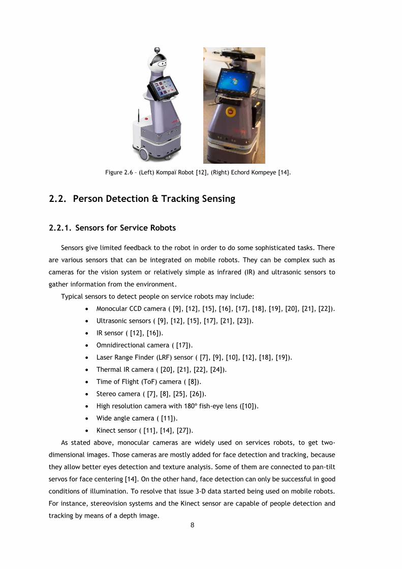
Figure 2.6 – (Left) Kompaï Robot [12], (Right) Echord Kompeye [14]. .............................. 8
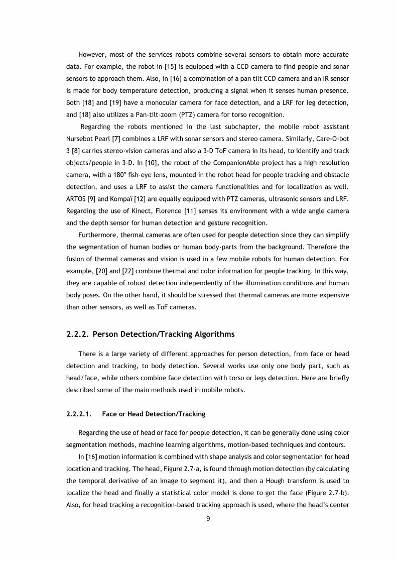
Figure 2.7 – (a) Input image, (b) skin color detection of Fig. 7-a, and (c) head tracking example
[16]. ...................................................................................................... 10
Figure 2.8 - Sequence of panoramic images and corresponding images from the face detector
in the right [17]. ....................................................................................... 10
Figure 2.9 – Successful multiple tracking with an occlusion situation [26]. ....................... 11
Figure 2.10 – Example of face detection algorithm [25]. ............................................. 11
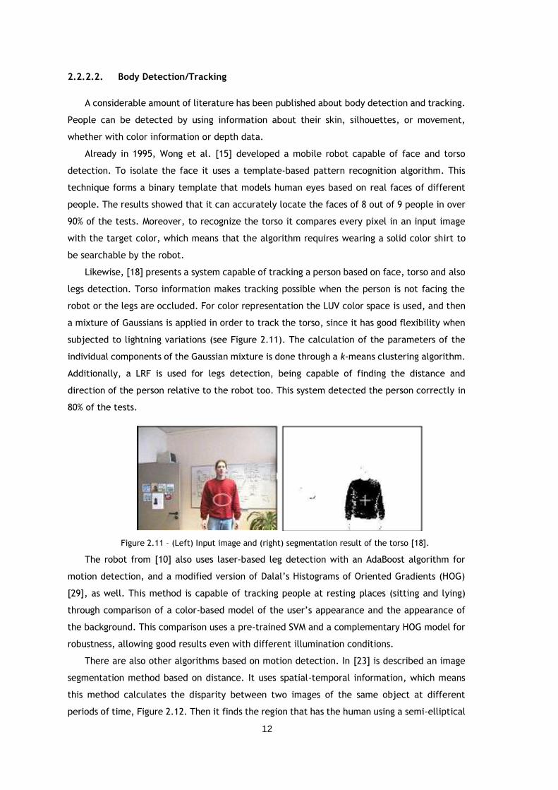
Figure 2.11 – (Left) Input image and (right) segmentation result of the torso [18]. ............. 12
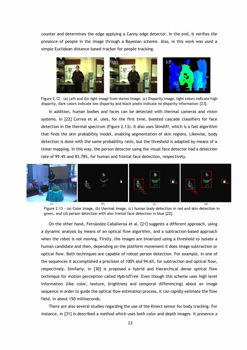
Figure 2.12 – (a) Left and (b) right image from stereo image. (c) Disparity image, light colors
indicate high disparity, dark colors indicate low disparity and black pixels indicate no
disparity information [23]. ........................................................................... 13
Figure 2.13 - (a) Color image, (b) thermal image, (c) human body detection in red and skin
detection in green, and (d) person detection with also frontal face detection in blue [22].
............................................................................................................ 13
Figure 2.14 - (a) Detection result with occlusion case, and (b) beyond Kinect’s depth range. (c)
Comparison between the algorithm with Deformable Parts Model upper body and full body
detector [31]. .......................................................................................... 14
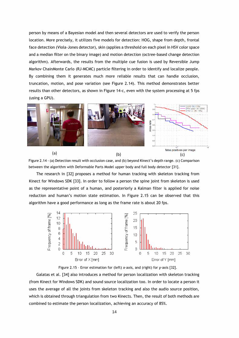
Figure 2.15 – Error estimation for (left) x-axis, and (right) for y-axis [32]. ....................... 14
Figure 2.16 - (a) - (c) Evolution of the filter from global uncertainty to successful localization
and tracking. (d) Tracking of a person even when that person is occluded repeatedly by a
second individual [7]. ................................................................................. 15
xiv
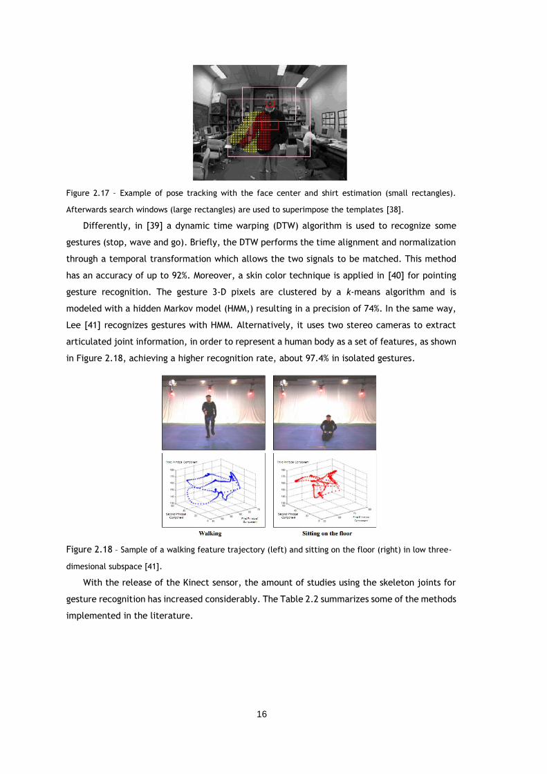
Figure 2.17 – Example of pose tracking with the face center and shirt estimation (small
rectangles). Afterwards search windows (large rectangles) are used to superimpose the
templates [38]. ........................................................................................ 16
Figure 2.18 – Sample of a walking feature trajectory (left) and sitting on the floor (right) in low
three-dimesional subspace [41]. ................................................................... 16
Figure 2.19 – Confusion matrix using (a) joint angle feature, and (b) in combination with the
relative joint position [42]........................................................................... 17
Figure 2.20 – Example where the classifier detects (left) open hand and (right) pointing gesture
[44]. ..................................................................................................... 18
Figure 2.21 – (a)-(d) Some of the extracted features for fall activity. Each x-axis represents the
frame number. At frame 70 the subject fell and got up at frame 121, approximately [48].
........................................................................................................... 18
Figure 2.22 - Values of three features for (top row) sitting and (bottom row) falling posture
[50]. ..................................................................................................... 19
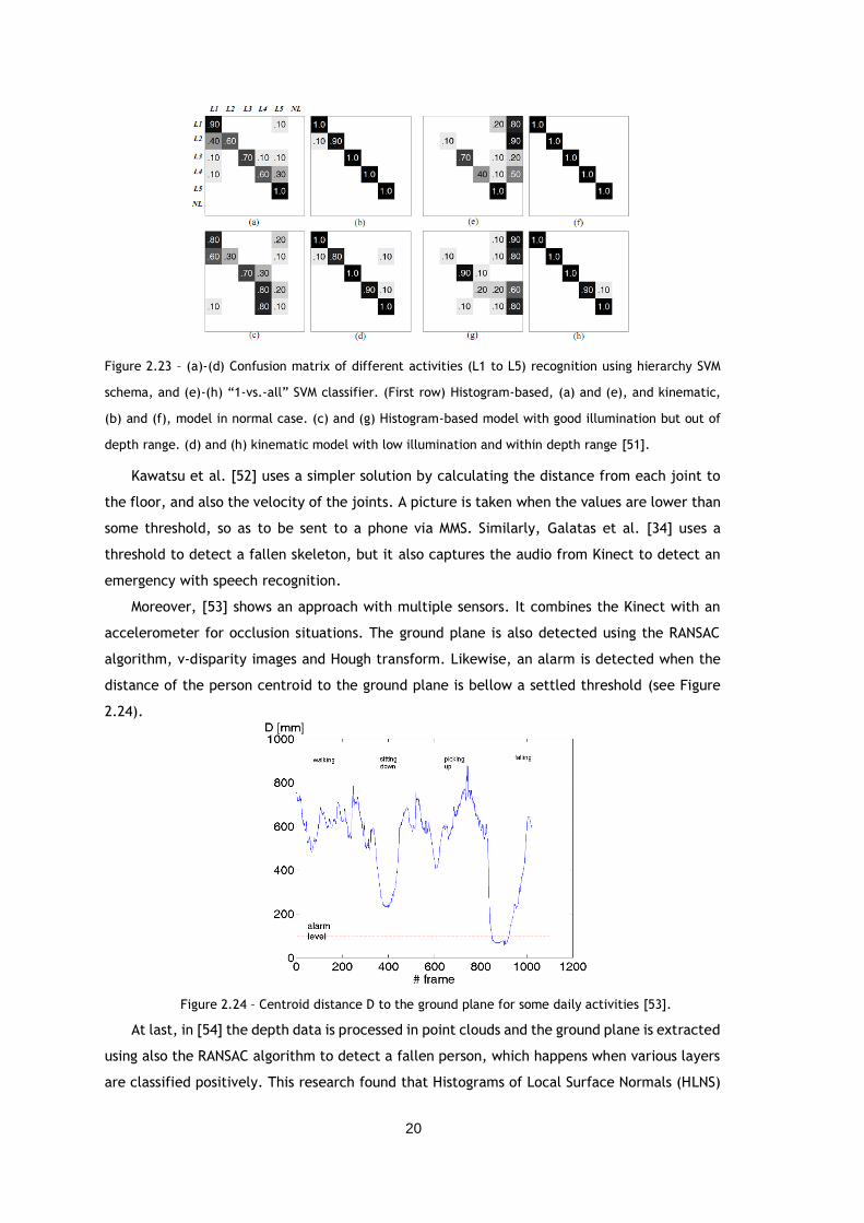
Figure 2.23 – (a)-(d) Confusion matrix of different activities (L1 to L5) recognition using
hierarchy SVM schema, and (e)-(h) “1-vs.-all” SVM classifier. (First row) Histogram-based,
(a) and (e), and kinematic, (b) and (f), model in normal case. (c) and (g) Histogram-based
model with good illumination but out of depth range. (d) and (h) kinematic model with
low illumination and within depth range [51]. ................................................... 20
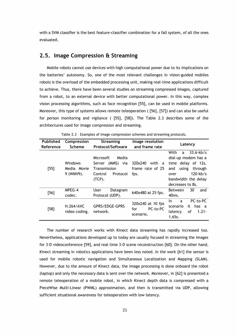
Figure 2.24 – Centroid distance D to the ground plane for some daily activities [53]. ......... 20
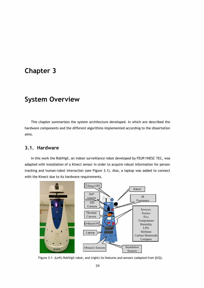
Figure 3.1- (Left) RobVigil robot, and (right) its features and sensors (adapted from [63]). .. 24
Figure 3.2 - Kinect for Windows sensor [33]. ........................................................... 25
Figure 3.3 – (a) Color, (b) IR, and (c) depth image of a scene with a resolution of 640x480. In
the last image depth values are represented with a grayscale from dark gray (near) to light
gray (far), and black color shows unknown depth data. ....................................... 25
Figure 3.4 - Illustration of Kinect limitations and optimal range (“sweet spot”) for (a) default
mode and (b) near mode. The “sweet spot” is where the sensor is able of doing all its
functions, such as skeleton and player tracking [33]. .......................................... 26
Figure 3.5 – Rotating platform (using a servo) with a 2D LRF [63].................................. 27
Figure 3.6 – (a) Example of a 3D occupancy grid, and (b) a slice of the distance matrix (with a
z coordinate of 1.8m) [63]. .......................................................................... 27
Figure 3.7 – Block representation of the system implemented for person following. Dashed lines
represent the information which was sent via UDP. ............................................ 28
Figure 4.1 - Basic shapes for Haar-Like features [67]. ................................................ 30
Figure 4.2 – Rejection cascade used in the Viola-Jones classifier (each node represents a “weak”
boosted classifier) [67]. .............................................................................. 30
Figure 4.3 – Block diagram for the face detection module. ......................................... 30
Figure 4.4 - Mean-shift algorithm in a 2-D array of data. Starts with an initial window
(rectangle), and then converges to a local mode (peak) of the distribution. The arrows
indicate the process of convergence [67]. ........................................................ 31
xv
Figure 4.5 – Block diagram of the method implemented for face tracking. ....................... 31
Figure 4.6 - Face Tracking example showing the result from backprojection. ................... 31
Figure 4.7 – Points that can be tracked with Kinect’s face tracking [68]. ......................... 32
Figure 4.8 – Representation of the skeleton’s 20 joints [70]. ........................................ 33
Figure 4.9 - Skeleton Cartesian coordinates, with Kinect located at the origin. ................. 33
Figure 4.10 – Kinect SDK’s methodology to find the skeletal joints. Colors in the middle indicate
the most likely body part that each pixel belongs to [71]. .................................... 33
Figure 4.11 – Segmentation of a person doing the calibration pose [72]. ......................... 34
Figure 4.12 – (a) Positive face detection, and (b) a false negative example, because of tilted
head. ..................................................................................................... 34
Figure 4.13 - Example of OpenCV’s internal detection rectangles when used zero as threshold
[73]. ...................................................................................................... 35
Figure 4.14 – Multiple face detection. ................................................................... 35
Figure 4.15 - Face probability with different values of smin and vmin. Images from left to right
show the result of increasing both values. ........................................................ 36
Figure 4.16 - Sequence of RGB images with the face tracking algorithm operational (in red). 36
Figure 4.17 – (a) Face tracking with head tilted, and (b) false positive face tracking because of
window light. ........................................................................................... 36
Figure 4.18 – Successful examples of Kinect SDK’s face tracking. .................................. 37
Figure 4.19 - (a) Skeleton tracking in depth images with the user facing the sensor, (b) standing
behind two chairs, (c) leaving the scene, and (d) sitting in a chair. ......................... 38
Figure 4.20 – Sequence of movements to recognize the wave gesture with left hand. ......... 39
Figure 4.21 – Depiction of angle α, in left arm. ........................................................ 39
Figure 4.22 – Sequence of movements for “stop” gesture with the right arm. ................... 40
Figure 4.23 – Finite-state machine diagram for the “stop” gesture, using the right arm. For left
arm is the same diagram, but using the left arm joints. ....................................... 41
Figure 4.24 – Representation of the “alarm” gesture. ................................................ 41
Figure 4.25 – Illustration of the distance d used for fall detection. ................................ 42
Figure 4.26 – Overview of the fall detection system implemented. Dashed line represents the
data sent via UDP. ..................................................................................... 43
Figure 4.27 – (Left) Server and (right) client scheme for image sending/receiving. The light blue
block represents the procedures in which the server/client sends packages to the
client/server, and the dark blue block corresponds to the phase where the server/client
receives information from the client/server [65]. ............................................... 44
Figure 4.28 - Messages transmitted between the server and the client [65]. .................... 44
Figure 4.29 – Acquisition examples for the (left) wave gesture and (right) fall situation. ..... 45
Figure 5.1 – Overview of the application implemented. Dashed lines represent the information
which was sent via UDP. .............................................................................. 46
Figure 5.2 – RobVigil rotation coordinate system. ..................................................... 48
xvi
Figure 5.3 – Kinect (top) and robot (bottom) coordinates system. Robot coordinates origin is
inside the robot, between the two wheels. ...................................................... 48
Figure 5.4 – Relative position between the person and the world referential (X-Y map). ..... 49
Figure 5.5 – Person tracking methodology. ............................................................. 50
Figure 5.6 – Function sendRotate diagram, in which sendStop, sendXYRot, and sendGo are
functions that send the messages 6, 4, and 5, respectively. CMx is the x coordinate of the
user’s center of mass. ................................................................................ 51
Figure 5.7 – Following control system. The variable nUsers represents the number of people
detected and c the torso joint confidence value. States and transitions with asterisk are
explained in the next images. ...................................................................... 52
Figure 5.8 - Detailed diagram of transition 1. ......................................................... 52
Figure 5.9 – Detailed diagram of transitions 2, 3, 4, and 5. Local and WP correspond to the
robot localization and the last waypoint sent to RobVigil, respectively. ................... 53
Figure 6.1 – (a) True positive (in red) and (b) false positive detection (in blue) due to metal
cabinet. ................................................................................................. 56
Figure 6.2 – (a) Multiple person detection and tracking of the closest person to the sensor. (b)
Positive skeleton tracking with several joints occluded. ...................................... 56
Figure 6.3 – Sequence of depth images with successful skeleton tracking. ....................... 57
Figure 6.4 – Correct robot person following (from point A to B) when person moved
forwards................................................................................................. 57
Figure 6.5 – Case where the person moved along a circular path, without leaving Kinect’s field-
of-view. Arrow represents the person movement direction. .................................. 58
Figure 6.6 – Successful person following where the person left the field-of-view several times.
Arrow represents the person movement direction. ............................................. 58
Figure 6.7 – Individual from database performing the 3 different gestures: (a)-(b) wave gesture
with left arm, (c)-(d) “stop” movements with left arm as well, and (e) “alarm”
gesture. ................................................................................................. 60
Figure 6.8 – Person following example with integration of gestures. .............................. 62
Figure 6.9 – Distance of the three joints to the ground plane for person falling. ............... 63
Figure 6.10 – (Left) Depth image with a fallen person, and (right) person sitting on the floor
(where the three joints head, neck and torso are far from the ground). ................... 63
Figure 6.11 – “Alarm” and fall detection while following a person. ............................... 64
Figure 6.12 – RGB image sent when a fall detection occurred. ..................................... 64
xvii
List of Tables
Table 2.1 – AAL robots functionalities examples. ....................................................... 4
Table 2.2 - Example of software and algorithms for gesture recognition. ........................ 17
Table 2.3 – Examples of image compression schemes and streaming protocols. ................. 21
Table 4.1 – Face detection and tracking limits and optimal ranges, and frame rate. ........... 37
Table 4.2 – Skeleton tracking distance capabilities and frame rate. ............................... 38
Table 5.1 - Messages sent to RobVigil, their functions, and needed parameters. ............... 47
Table 5.2 – Messages sent to RobVigil according to the posture recognized and flag Go
state...................................................................................................... 54
Table 6.1 – Processing time of image acquisition, skeleton tracking and UDP
communication. ........................................................................................ 59
Table 6.2 – Mean frame rate obtained with RobVigil stopped and in movement. ................ 59
Table 6.3 – Confusion matrix for the three gestures. ................................................. 61
Table 6.4 – Accuracy and precision of each gesture. .................................................. 61
Table 6.5 – Results for image compression and streaming (in the server) in milliseconds. .... 65
Table 6.6. Results for the streaming system (in the client) in milliseconds. ..................... 65
xviii
Abbreviations
2-D Two Dimensional
3-D Three Dimensional
AAL Ambient Assisted Living
ANMM Average Neighborhood Margin Maximization
API Application Programming Interface
ARTOS Autonomous Robot for Transport and Service
BAP Body Action and Posture
CCD Charge-coupled device
cm centimeter
CPU Central Processing Unit
CAMSHIFT Continuously Adaptive Mean Shift
DOF Degrees of freedom
DTW Dynamic Time Warping
EU European Union
EKF Extended Kalman Filter
FEUP Faculdade de Engenharia da Universidade do Porto
FSM Finite-State Machine
fps frames per second
GPU Graphics Processing Unit
HMM hidden Markov model
HOG Histogram of oriented gradients
HRI Human-Robot Interaction
HSV Hue, Saturation and value (Brightness)
IR Infrared
INESC TEC Instituto de Engenharia de Sistemas e Computadores Tecnologia e Ciência
JPEG Joint Photographic Experts Group
LBP Local Binary Pattern
xix
LRF Laser range finder
m meter
NN Neural network
ONI OpenNI files format
OpenCV Open Source Computer Vision
OpenNI Open Natural Interaction
PC Personal Computer
PCA Principal Components Analysis
PTZ Pan–tilt–zoom
PWML PieceWise Multi-Linear
RAM Random Access Memory
RANSAC RANdom SAmple Consensus
RBDAPF Rao-Blackwellized Data Association Particle Filter
RFID Radio-Frequency Identification
RGB Red, Green and Blue
SDK Software Development Kit
SIFT Scale-Invariant Feature Transform
SLAM Simultaneous Localization and Mapping
SVM Support vector machine
TCP Transmission Control Protocol
ToF Time of flight
UDP User Datagram Protocol

xx
Chapter 1
Introduction
This section states briefly the context and goals behind this dissertation, as well as its
contribution and the document outline.
1.1. Context and Motivation
Service robots have become part of our society over the last decades, and have been used
in several activities to assist people. Those intelligent service robots must be capable of making
decisions in real-time autonomously and in different environments to provide useful services
to humans. They are currently applied in hospitals, department stores and museums where the
main tasks performed are to deliver meals and mail, janitorial services, educate and entertain
[1].
Nowadays, service robots started to be designed for personal use as well. Some successful
examples are robots for household, such as vacuum cleaning and lawn-mowing robots, and toy
robots for entertainment. Also, a recent application of services robots is the homecare area.
It is known that the number of elderly in developed countries has been increasing
progressively, as people tend to live more years. From 1990 to 2010 the mean life expectancy
increased about 6 years, in all of the EU Member States [2]. Thus, the number of elder people
needing long-term care has also increased dramatically.
It is more viable and desirable for older people to live at home as long as possible.
According to the Economic and Financial Affairs Council of the European Union, in 2004, the
average cost for taking care of one elderly in an institution was about 24.000€, while taking
care at home was about 9.400€, in EU15 [3]. This means that the demand for caregivers will
surpass the number of individuals working in such field.
2
As a result, there has been a lot of research and development of socially assistive robotics
for elderly or handicapped people in the last few years. These type of robots represent an
important component of the concept known as Ambient Assisted Living (AAL), which represents
the systems that can promote a better quality of life for elderly or handicapped people, by
prolonging the time those individuals can live at their own home, independently and self-
confident.
Therefore, AAL robots must have several capabilities to interact in home environments,
such as mobility and different perceptual skills (like emergency recognition, immobility
detection, medication reminder) in order to contribute to the wellbeing of those individuals.
1.2. Objectives
This dissertation contributes to the development of such AAL platform. The main objective
of this dissertation was to study sensing (sensors and algorithms) for person tracking and
human-robot interaction in the scope of its integration in a mobile robotic platform for AAL.
The Kinect sensor was considered because it has a color camera and a depth sensor.
Therefore, one of the objectives was to elaborate a literature review which shows that Kinect
can be a good option for human-robot interaction. Posteriorly, different algorithms were
implemented and tested for person detection/tracking, gesture recognition and fall detection.
Lastly, these algorithms were also tested and compared in the RobVigil, an indoor surveillance
robot developed by FEUP/INESC TEC, in order to create a system adequate for people
assistance.
1.3. Contributions
This work contributes to the study of Kinect sensor for ambient assisting living purposes,
through the application of algorithms for person tracking, gesture recognition and fall
detection. The results include:
Creation of a database of fall situation and gesture recognition taken by the
Kinect and its manual annotation;
Integration of skeleton tracking algorithm on RobVigil platform;
Recognition algorithm for three gestures (“alarm”, wave and “stop”) from
depth data;
Detection algorithm for fallen person from depth data, and color image
streaming to a care center when a fall occurs;
Article published in the International Workshop on Healthcare Robotics
(HealthRob 2013) with the title “Evaluation of sensors and algorithms for person
detection for personal robots” [4].
3
1.4. Structure of the Document
This dissertation is divided into 7 chapters. Following Chapter 1 (Introduction), the
dissertation is organized as follows:
Chapter 2 presents the literature review of some published work related to AAL
robots, describing the main sensors and algorithms used in such robots. Special
attention is given to the algorithms for face detection and tracking, and also body
detection and tracking. In the next subchapters, different approaches for gesture
recognition, fall detection and image streaming schemes are described. In
addition, the last subchapter presents all the conclusions from this bibliographic
survey.
Chapter 3 provides a system overview of the framework developed in this
dissertation, describing the hardware components and the software implemented.
Chapter 4 explains the vision system modules. More precisely, the algorithms
employed for people tracking, gesture recognition, fall detection, and image
compression and streaming. Moreover, some preliminary results are presented for
people tracking. At last, a brief description about the database constructed is
presented.
Chapter 5 describes all the methodology necessary to control the platform
RobVigil, as well as the system developed to have a person following robot with
human-robot interaction. The transformations between the robot and the Kinect
referential are also described.
Chapter 6 shows a set of experiments applied on RobVigil and their results are
discussed. The database results are also accessed and discussed.
Chapter 7 presents the major conclusions of this dissertation and some notes
regarding future work.
4
Chapter 2
Literature Review
This chapter presents the state-of-the-art of AAL and others service robots, focusing on the
sensing used. The information is provided taking into account the dissertation’s objectives, in
order to be aware of the currently existing methods for tracking people, fall detection, gesture
recognition, and image compression and streaming.
2.1. AAL Robots
In the past few years there has been a lot of research about a new concept called AAL. It
can be defined as all the assisting systems that provide a better quality of life for elderly or
handicapped people, allowing them to live at home as long as possible, independently and self-
confident, supporting security, health monitoring and the multifunctional network around the
person [5].
Therefore, studies about socially assistive robotics for domestic use have increased
significantly [6]. Currently various AAL robots were developed. These robots must have some
robust capabilities to interact in human-populated environments. The Table 2.1 shows recent
developments in robotics for AAL organized by their main functionalities.
Table 2.1 – AAL robots functionalities examples.
Functionalities Published references
Person guidance [7], [8]
Communication through video-call [9], [10], [11], [12], [13]
Medication reminder [7], [10], [11]
Therapy activities [10], [11]
Access to Internet services [12]
Fall detection and other medical emergency situations [9], [10], [11], [13], [14]
5
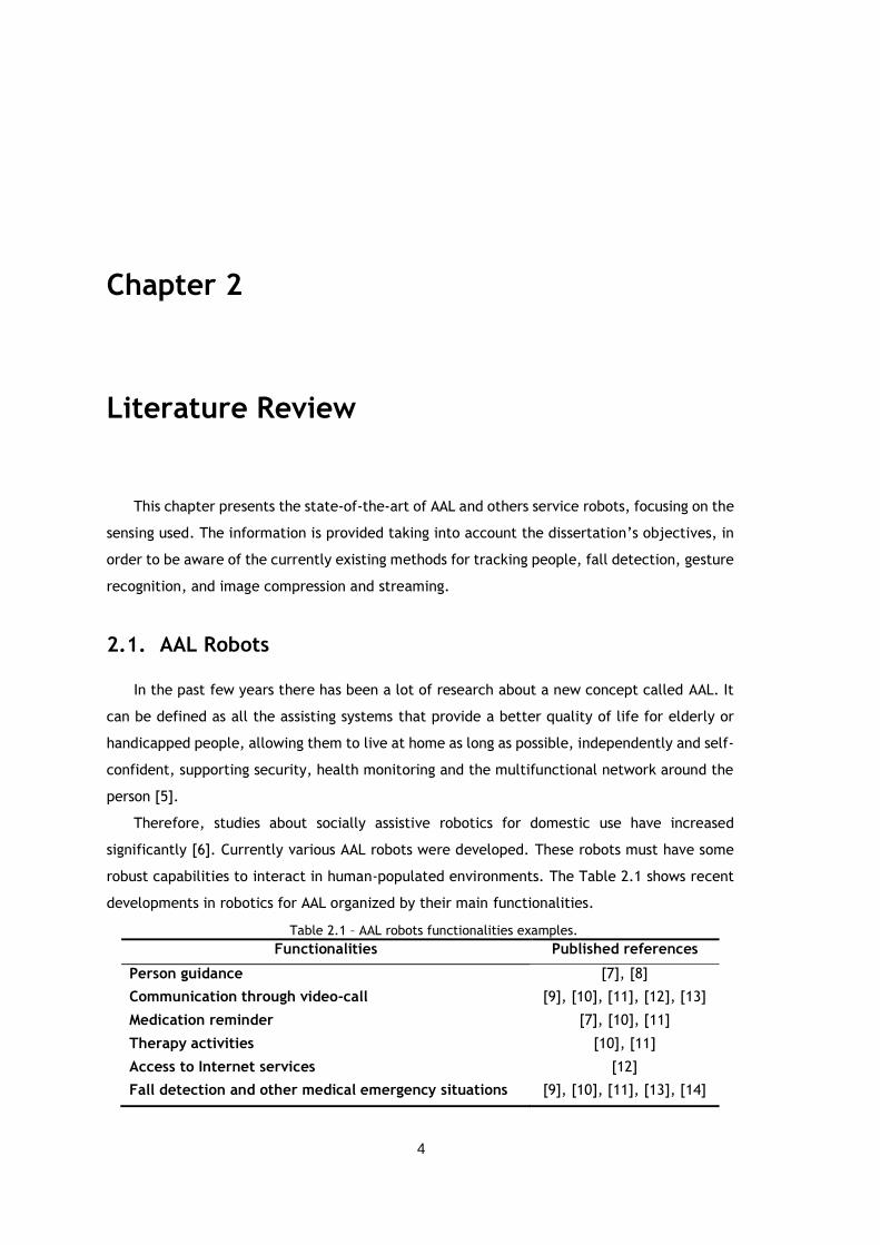
Pineau et al. [7] developed a prototype autonomous mobile robot assistant – the Nursebot
Pearl. This robot can assist elderly individuals with physical and mild cognitive impairments. It
interacts with humans through speech, visual displays, facial expressions and physical motion.
Pearl provides an automated reminder system (the Autominder), which can remember the
elderly of their daily activity, and comes with two sturdy handle-bars to help them walk, Figure
2.1. Also, it has a people tracking and detection system and a controller to select the
appropriated course of actions. It can present weather reports or television schedules, as well.
Figure 2.1 - Nursebot Pearl assisting an elderly person [7].
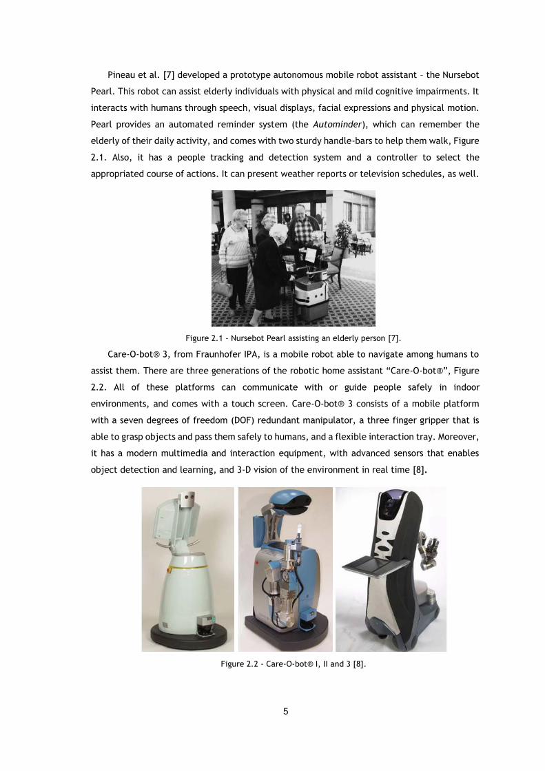
Care-O-bot® 3, from Fraunhofer IPA, is a mobile robot able to navigate among humans to
assist them. There are three generations of the robotic home assistant “Care-O-bot®”, Figure
2.2. All of these platforms can communicate with or guide people safely in indoor
environments, and comes with a touch screen. Care-O-bot® 3 consists of a mobile platform
with a seven degrees of freedom (DOF) redundant manipulator, a three finger gripper that is
able to grasp objects and pass them safely to humans, and a flexible interaction tray. Moreover,
it has a modern multimedia and interaction equipment, with advanced sensors that enables
object detection and learning, and 3-D vision of the environment in real time [8].
Figure 2.2 - Care-O-bot® I, II and 3 [8].
6
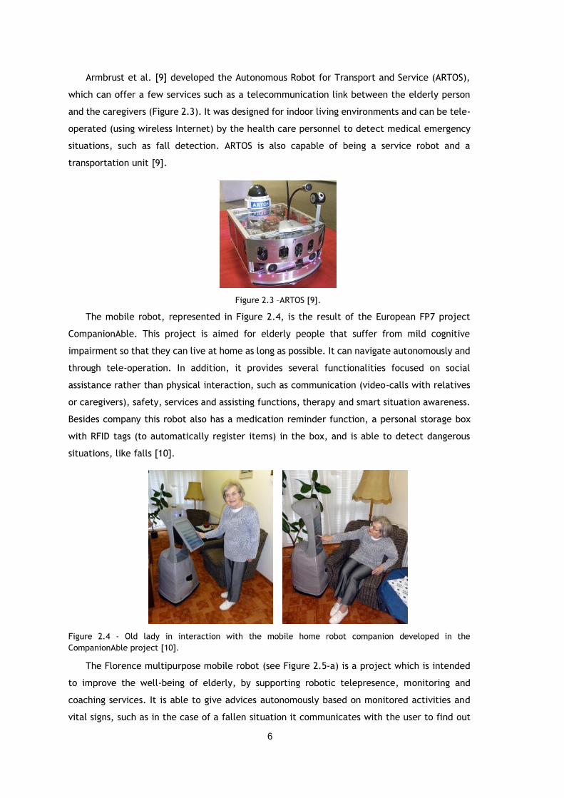
Armbrust et al. [9] developed the Autonomous Robot for Transport and Service (ARTOS),
which can offer a few services such as a telecommunication link between the elderly person
and the caregivers (Figure 2.3). It was designed for indoor living environments and can be tele-
operated (using wireless Internet) by the health care personnel to detect medical emergency
situations, such as fall detection. ARTOS is also capable of being a service robot and a
transportation unit [9].
Figure 2.3 –ARTOS [9].
The mobile robot, represented in Figure 2.4, is the result of the European FP7 project
CompanionAble. This project is aimed for elderly people that suffer from mild cognitive
impairment so that they can live at home as long as possible. It can navigate autonomously and
through tele-operation. In addition, it provides several functionalities focused on social
assistance rather than physical interaction, such as communication (video-calls with relatives
or caregivers), safety, services and assisting functions, therapy and smart situation awareness.
Besides company this robot also has a medication reminder function, a personal storage box
with RFID tags (to automatically register items) in the box, and is able to detect dangerous
situations, like falls [10].
Figure 2.4 - Old lady in interaction with the mobile home robot companion developed in the
CompanionAble project [10].
The Florence multipurpose mobile robot (see Figure 2.5-a) is a project which is intended
to improve the well-being of elderly, by supporting robotic telepresence, monitoring and
coaching services. It is able to give advices autonomously based on monitored activities and
vital signs, such as in the case of a fallen situation it communicates with the user to find out
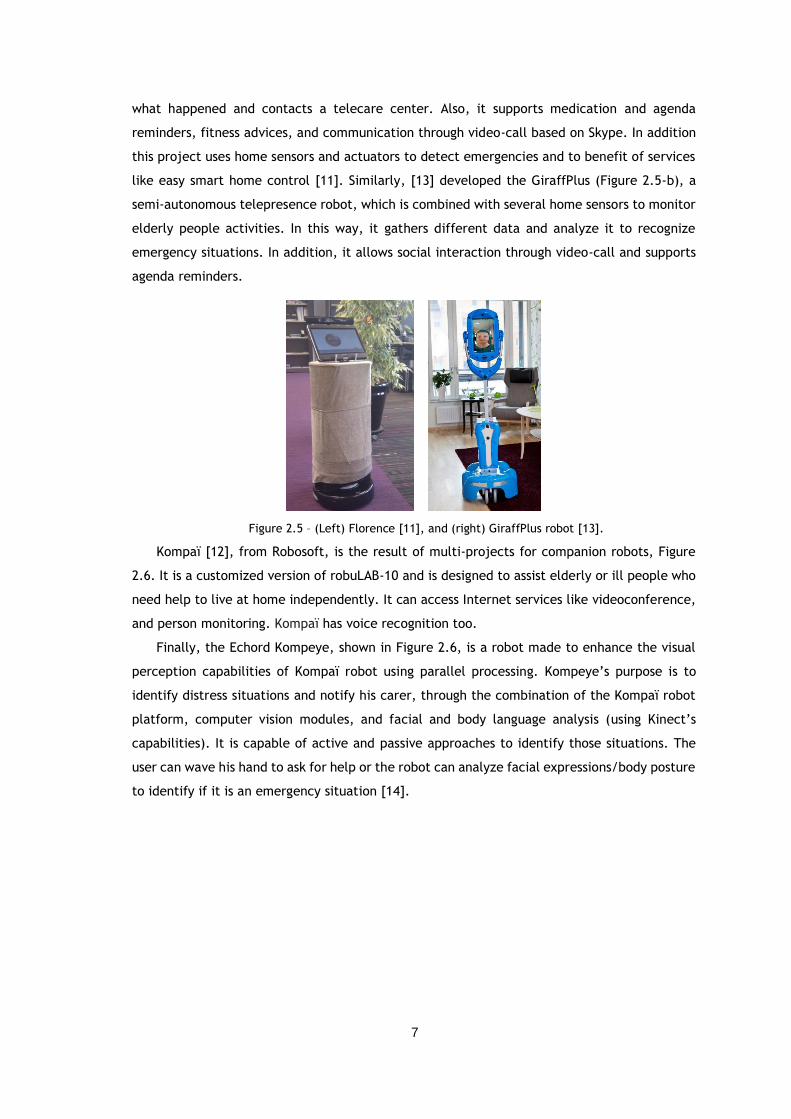
7
what happened and contacts a telecare center. Also, it supports medication and agenda
reminders, fitness advices, and communication through video-call based on Skype. In addition
this project uses home sensors and actuators to detect emergencies and to benefit of services
like easy smart home control [11]. Similarly, [13] developed the GiraffPlus (Figure 2.5-b), a
semi-autonomous telepresence robot, which is combined with several home sensors to monitor
elderly people activities. In this way, it gathers different data and analyze it to recognize
emergency situations. In addition, it allows social interaction through video-call and supports
agenda reminders.
Figure 2.5 – (Left) Florence [11], and (right) GiraffPlus robot [13].
Kompaï [12], from Robosoft, is the result of multi-projects for companion robots, Figure
2.6. It is a customized version of robuLAB-10 and is designed to assist elderly or ill people who
need help to live at home independently. It can access Internet services like videoconference,
and person monitoring. Kompaï has voice recognition too.
Finally, the Echord Kompeye, shown in Figure 2.6, is a robot made to enhance the visual
perception capabilities of Kompaï robot using parallel processing. Kompeye’s purpose is to
identify distress situations and notify his carer, through the combination of the Kompaï robot
platform, computer vision modules, and facial and body language analysis (using Kinect’s
capabilities). It is capable of active and passive approaches to identify those situations. The
user can wave his hand to ask for help or the robot can analyze facial expressions/body posture
to identify if it is an emergency situation [14].
8
Figure 2.6 – (Left) Kompaï Robot [12], (Right) Echord Kompeye [14].
2.2. Person Detection & Tracking Sensing
2.2.1. Sensors for Service Robots
Sensors give limited feedback to the robot in order to do some sophisticated tasks. There
are various sensors that can be integrated on mobile robots. They can be complex such as
cameras for the vision system or relatively simple as infrared (IR) and ultrasonic sensors to
gather information from the environment.
Typical sensors to detect people on service robots may include:
Monocular CCD camera ( [9], [12], [15], [16], [17], [18], [19], [20], [21], [22]).
Ultrasonic sensors ( [9], [12], [15], [17], [21], [23]).
IR sensor ( [12], [16]).
Omnidirectional camera ( [17]).
Laser Range Finder (LRF) sensor ( [7], [9], [10], [12], [18], [19]).
Thermal IR camera ( [20], [21], [22], [24]).
Time of Flight (ToF) camera ( [8]).
Stereo camera ( [7], [8], [25], [26]).
High resolution camera with 180º fish-eye lens ([10]).
Wide angle camera ( [11]).
Kinect sensor ( [11], [14], [27]).
As stated above, monocular cameras are widely used on services robots, to get two-
dimensional images. Those cameras are mostly added for face detection and tracking, because
they allow better eyes detection and texture analysis. Some of them are connected to pan-tilt
servos for face centering [14]. On the other hand, face detection can only be successful in good
conditions of illumination. To resolve that issue 3-D data started being used on mobile robots.
For instance, stereovision systems and the Kinect sensor are capable of people detection and
tracking by means of a depth image.
9
However, most of the services robots combine several sensors to obtain more accurate
data. For example, the robot in [15] is equipped with a CCD camera to find people and sonar
sensors to approach them. Also, in [16] a combination of a pan tilt CCD camera and an IR sensor
is made for body temperature detection, producing a signal when it senses human presence.
Both [18] and [19] have a monocular camera for face detection, and a LRF for leg detection,
and [18] also utilizes a Pan–tilt–zoom (PTZ) camera for torso recognition.
Regarding the robots mentioned in the last subchapter, the mobile robot assistant
Nursebot Pearl [7] combines a LRF with sonar sensors and stereo camera. Similarly, Care-O-bot
3 [8] carries stereo-vision cameras and also a 3-D ToF camera in its head, to identify and track
objects/people in 3-D. In [10], the robot of the CompanionAble project has a high resolution
camera, with a 180º fish-eye lens, mounted in the robot head for people tracking and obstacle
detection, and uses a LRF to assist the camera functionalities and for localization as well.
ARTOS [9] and Kompaï [12] are equally equipped with PTZ cameras, ultrasonic sensors and LRF.
Regarding the use of Kinect, Florence [11] senses its environment with a wide angle camera
and the depth sensor for human detection and gesture recognition.
Furthermore, thermal cameras are often used for people detection since they can simplify
the segmentation of human bodies or human body-parts from the background. Therefore the
fusion of thermal cameras and vision is used in a few mobile robots for human detection. For
example, [20] and [22] combine thermal and color information for people tracking. In this way,
they are capable of robust detection independently of the illumination conditions and human
body poses. On the other hand, it should be stressed that thermal cameras are more expensive
than other sensors, as well as ToF cameras.
2.2.2. Person Detection/Tracking Algorithms
There is a large variety of different approaches for person detection, from face or head
detection and tracking, to body detection. Several works use only one body part, such as
head/face, while others combine face detection with torso or legs detection. Here are briefly
described some of the main methods used in mobile robots.
2.2.2.1. Face or Head Detection/Tracking
Regarding the use of head or face for people detection, it can be generally done using color
segmentation methods, machine learning algorithms, motion-based techniques and contours.
In [16] motion information is combined with shape analysis and color segmentation for head
location and tracking. The head, Figure 2.7-a, is found through motion detection (by calculating
the temporal derivative of an image to segment it), and then a Hough transform is used to
localize the head and finally a statistical color model is done to get the face (Figure 2.7-b).
Also, for head tracking a recognition-based tracking approach is used, where the head’s center
10
is the parameter chosen for tracking (Figure 2.7-c). Besides that, when there is no information
from motion detection it resorts to color information, which stabilizes the tracking and
prevents the system from losing the position information.
Figure 2.7 – (a) Input image, (b) skin color detection of Fig. 7-a, and (c) head tracking example [16].
There are also face detection methods which are based on the use of machine learning
algorithms, such as boosting classifiers [22] and Support Vector Machines (SVM) [26]. For
instance, the framework proposed by Viola and Jones [28] is one of the most popular face
detection paradigm utilized in several works [10], [17], [18] and [19]. This algorithm is based
on the use of cascades of boosted classifiers, which allows efficient and fast detection of faces
with very low false positive rates.
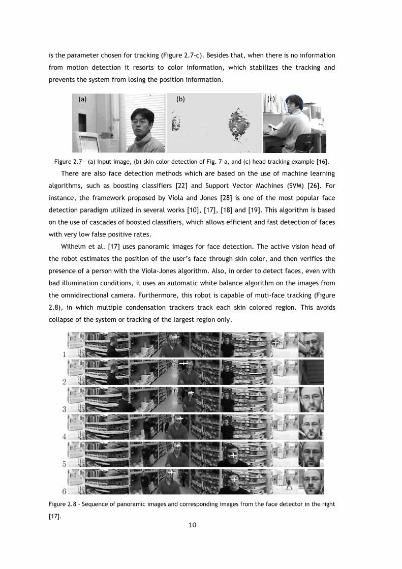
Wilhelm et al. [17] uses panoramic images for face detection. The active vision head of
the robot estimates the position of the user’s face through skin color, and then verifies the
presence of a person with the Viola-Jones algorithm. Also, in order to detect faces, even with
bad illumination conditions, it uses an automatic white balance algorithm on the images from
the omnidirectional camera. Furthermore, this robot is capable of muti-face tracking (Figure
2.8), in which multiple condensation trackers track each skin colored region. This avoids
collapse of the system or tracking of the largest region only.
Figure 2.8 - Sequence of panoramic images and corresponding images from the face detector in the right
[17].
(a) (b) (c)
11
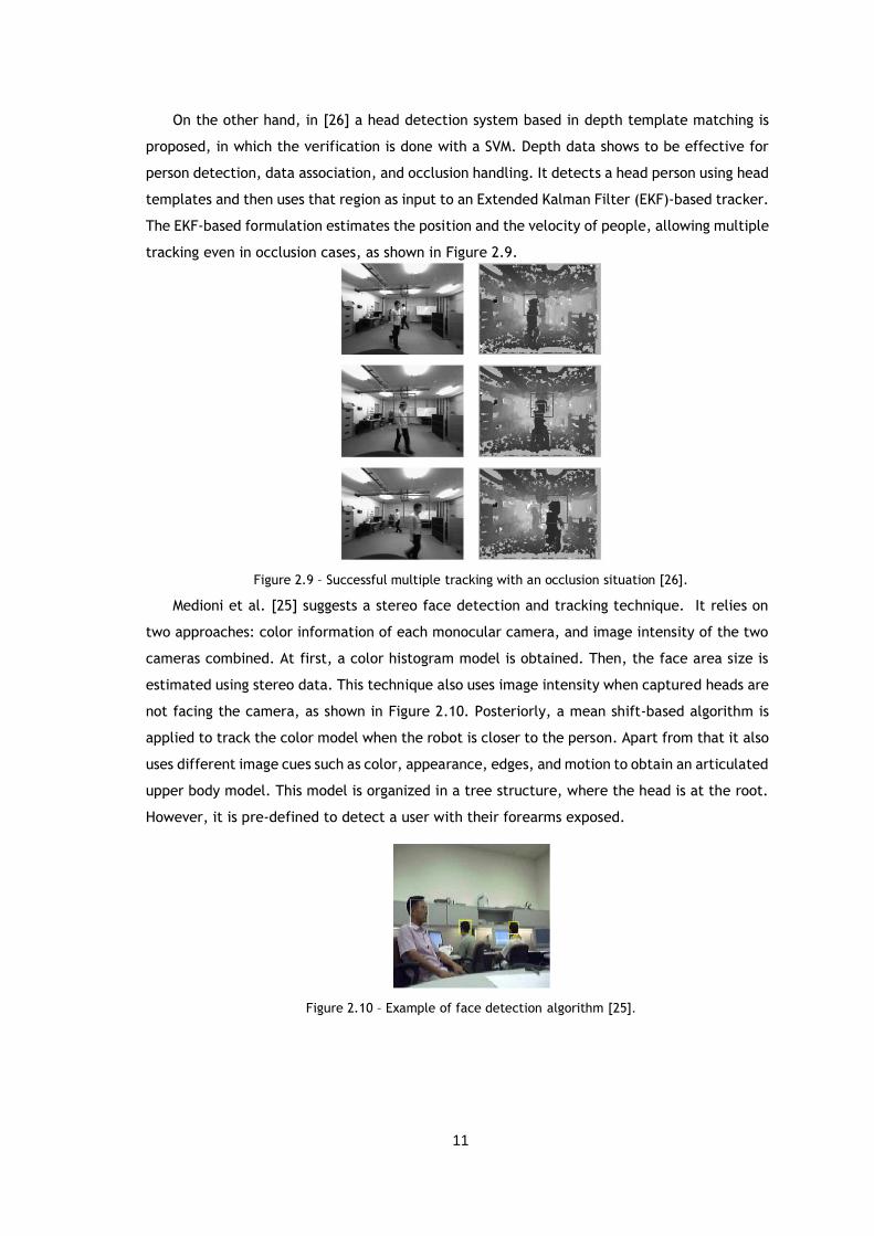
On the other hand, in [26] a head detection system based in depth template matching is
proposed, in which the verification is done with a SVM. Depth data shows to be effective for
person detection, data association, and occlusion handling. It detects a head person using head
templates and then uses that region as input to an Extended Kalman Filter (EKF)-based tracker.
The EKF-based formulation estimates the position and the velocity of people, allowing multiple
tracking even in occlusion cases, as shown in Figure 2.9.
Figure 2.9 – Successful multiple tracking with an occlusion situation [26].
Medioni et al. [25] suggests a stereo face detection and tracking technique. It relies on
two approaches: color information of each monocular camera, and image intensity of the two
cameras combined. At first, a color histogram model is obtained. Then, the face area size is
estimated using stereo data. This technique also uses image intensity when captured heads are
not facing the camera, as shown in Figure 2.10. Posteriorly, a mean shift-based algorithm is
applied to track the color model when the robot is closer to the person. Apart from that it also
uses different image cues such as color, appearance, edges, and motion to obtain an articulated
upper body model. This model is organized in a tree structure, where the head is at the root.
However, it is pre-defined to detect a user with their forearms exposed.
Figure 2.10 – Example of face detection algorithm [25].
12
2.2.2.2. Body Detection/Tracking
A considerable amount of literature has been published about body detection and tracking.
People can be detected by using information about their skin, silhouettes, or movement,
whether with color information or depth data.
Already in 1995, Wong et al. [15] developed a mobile robot capable of face and torso
detection. To isolate the face it uses a template-based pattern recognition algorithm. This
technique forms a binary template that models human eyes based on real faces of different
people. The results showed that it can accurately locate the faces of 8 out of 9 people in over
90% of the tests. Moreover, to recognize the torso it compares every pixel in an input image
with the target color, which means that the algorithm requires wearing a solid color shirt to
be searchable by the robot.
Likewise, [18] presents a system capable of tracking a person based on face, torso and also
legs detection. Torso information makes tracking possible when the person is not facing the
robot or the legs are occluded. For color representation the LUV color space is used, and then
a mixture of Gaussians is applied in order to track the torso, since it has good flexibility when
subjected to lightning variations (see Figure 2.11). The calculation of the parameters of the
individual components of the Gaussian mixture is done through a k-means clustering algorithm.
Additionally, a LRF is used for legs detection, being capable of finding the distance and
direction of the person relative to the robot too. This system detected the person correctly in
80% of the tests.
Figure 2.11 – (Left) Input image and (right) segmentation result of the torso [18].
The robot from [10] also uses laser-based leg detection with an AdaBoost algorithm for
motion detection, and a modified version of Dalal’s Histograms of Oriented Gradients (HOG)
[29], as well. This method is capable of tracking people at resting places (sitting and lying)
through comparison of a color-based model of the user’s appearance and the appearance of
the background. This comparison uses a pre-trained SVM and a complementary HOG model for
robustness, allowing good results even with different illumination conditions.
There are also other algorithms based on motion detection. In [23] is described an image
segmentation method based on distance. It uses spatial-temporal information, which means
this method calculates the disparity between two images of the same object at different
periods of time, Figure 2.12. Then it finds the region that has the human using a semi-elliptical
13
counter and determines the edge applying a Canny edge detector. In the end, it verifies the
presence of people in the image through a Bayesian scheme. Also, in this work was used a
simple Euclidean distance based tracker for people tracking.
Figure 2.12 – (a) Left and (b) right image from stereo image. (c) Disparity image, light colors indicate high
disparity, dark colors indicate low disparity and black pixels indicate no disparity information [23].
In addition, human bodies and faces can be detected with thermal cameras and vision
systems. In [22] Correa et al. uses, for the first time, boosted cascade classifiers for face
detection in the thermal spectrum (Figure 2.13). It also uses Skindiff, which is a fast algorithm
that finds the skin probability model, enabling segmentation of skin regions. Likewise, body
detection is done with the same probability ratio, but the threshold is adapted by means of a
linear mapping. In this way, the person detector using the visual face detector had a detection
rate of 99.4% and 83.78%, for human and frontal face detection, respectively.
On the other hand, Fernández-Caballeroa et al. [21] suggests a different approach, using
a dynamic analysis by means of an optical flow algorithm, and a subtraction-based approach
when the robot is not moving. Firstly, the images are binarized using a threshold to isolate a
human candidate and then, depending on the platform movement it does image subtraction or
optical flow. Both techniques are capable of robust person detection. For example, in one of
the sequences it accomplished a precision of 100% and 94.6%, for subtraction and optical flow,
respectively. Similarly, in [30] is proposed a hybrid and hierarchical dense optical flow
technique for motion perception called HybridTree. Even though this scheme uses high level
information (like color, texture, brightness and temporal differencing) about an image
sequence in order to guide the optical flow estimation process, it can rapidly estimate the flow
field, in about 150 milliseconds.
There are also several studies regarding the use of the Kinect sensor for body tracking. For
instance, in [31] is described a method which uses both color and depth images. It presence a
Figure 2.13 - (a) Color image, (b) thermal image, (c) human body detection in red and skin detection in
green, and (d) person detection with also frontal face detection in blue [22].
(a) (b) (c)
14
person by means of a Bayesian model and then several detectors are used to verify the person
location. More precisely, it utilizes five models for detection: HOG, shape from depth, frontal
face detection (Viola-Jones detector), skin (applies a threshold on each pixel in HSV color space
and a median filter on the binary image) and motion detection (octree-based change detection
algorithm). Afterwards, the results from the multiple cue fusion is used by Reversible Jump
Markov ChainMonte Carlo (RJ-MCMC) particle filtering in order to identify and localize people.
By combining them it generates much more reliable results that can handle occlusion,
truncation, motion, and pose variation (see Figure 2.14). This method demonstrates better
results than other detectors, as shown in Figure 14-c, even with the system processing at 5 fps
(using a GPU).
The research in [32] proposes a method for human tracking with skeleton tracking from
Kinect for Windows SDK [33]. In order to follow a person the spine joint from skeleton is used
as the representative point of a human, and posteriorly a Kalman filter is applied for noise
reduction and human’s motion state estimation. In Figure 2.15 can be observed that this
algorithm have a good performance as long as the frame rate is about 20 fps.
Figure 2.15 – Error estimation for (left) x-axis, and (right) for y-axis [32].
Galatas et al. [34] also introduces a method for person localization with skeleton tracking
(from Kinect for Windows SDK) and sound source localization too. In order to locate a person it
uses the average of all the joints from skeleton tracking and also the audio source position,
which is obtained through triangulation from two Kinects. Then, the result of both methods are
combined to estimate the person localization, achieving an accuracy of 85%.
(a) (b) (c)
Figure 2.14 - (a) Detection result with occlusion case, and (b) beyond Kinect’s depth range. (c) Comparison
between the algorithm with Deformable Parts Model upper body and full body detector [31].
15
Furthermore, the Echord Kompeye robot [14] uses OpenNI library [35] and NITE middleware
[36] to track body parts, LBP (Local Binary Pattern) and Haar-like features for face detection,
and a Rao-Blackwellized data association particle filter (RBDAPF) for upper body tracking. In
the same vein, Pineau et al. [7] employed a similar filter to RBDAPF on Pearl (Figure 2.16), in
which each particle in that filter represents an estimative of the person position.
2.3. Gesture Sensing
Human-computer interaction has become a popular area of research, and hand gesture
recognition is an emerging example of communication between humans and machines in a
natural way.
Gestures can be recognized with wearable sensors and vision-based systems. There are
glove-based systems to capture hand motion and accelerometers approaches [37], for instance.
Regarding vision sensors, different cameras have been used in these area. For example,
monocular CCD cameras [38], [39], stereo cameras [40], [41], and more recently, the Kinect
sensor [42], [43], [44], [45].
Several approaches have been studied for the last decades. In 2000, [38] presented two
methods, a template based approach and a neural network approach, for hand gestures
recognition involving arm motion. Both are combined with the Viterbi algorithm to match an
image data with pre-defined temporal templates (see Figure 2.17). The two methods achieved
equally an accuracy of 97%.
Figure 2.16 - (a) - (c) Evolution of the filter from global uncertainty to successful localization and tracking.
(d) Tracking of a person even when that person is occluded repeatedly by a second individual [7].
16
Figure 2.17 – Example of pose tracking with the face center and shirt estimation (small rectangles).
Afterwards search windows (large rectangles) are used to superimpose the templates [38].
Differently, in [39] a dynamic time warping (DTW) algorithm is used to recognize some
gestures (stop, wave and go). Briefly, the DTW performs the time alignment and normalization
through a temporal transformation which allows the two signals to be matched. This method
has an accuracy of up to 92%. Moreover, a skin color technique is applied in [40] for pointing
gesture recognition. The gesture 3-D pixels are clustered by a k-means algorithm and is
modeled with a hidden Markov model (HMM,) resulting in a precision of 74%. In the same way,
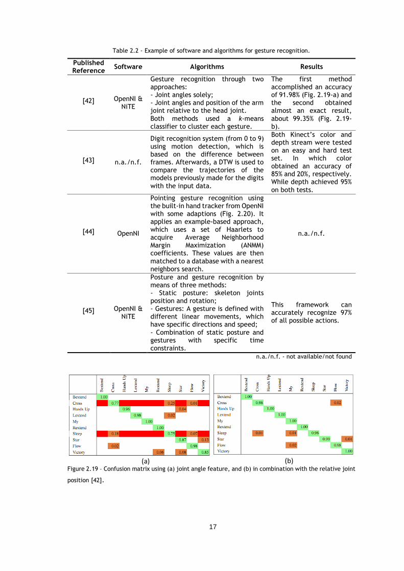
Lee [41] recognizes gestures with HMM. Alternatively, it uses two stereo cameras to extract
articulated joint information, in order to represent a human body as a set of features, as shown
in Figure 2.18, achieving a higher recognition rate, about 97.4% in isolated gestures.
Figure 2.18 – Sample of a walking feature trajectory (left) and sitting on the floor (right) in low three-
dimesional subspace [41].
With the release of the Kinect sensor, the amount of studies using the skeleton joints for
gesture recognition has increased considerably. The Table 2.2 summarizes some of the methods
implemented in the literature.
17
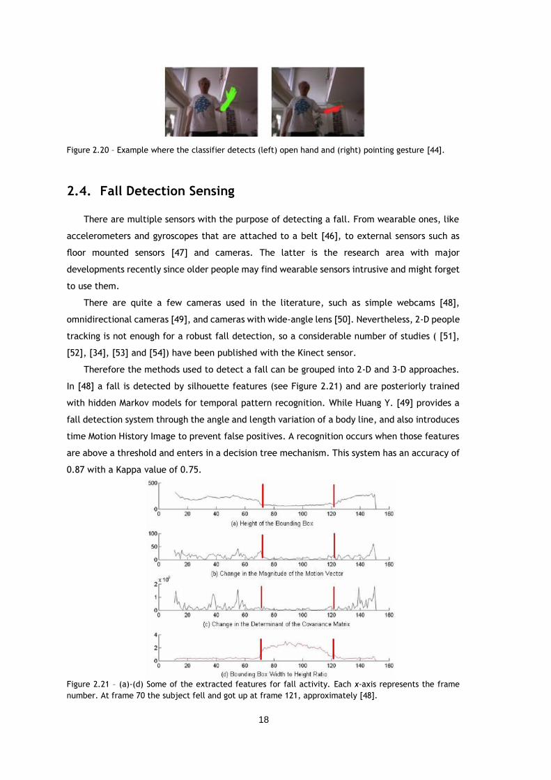
Table 2.2 - Example of software and algorithms for gesture recognition.
Published Reference
Software Algorithms Results
[42] OpenNI & NiTE
Gesture recognition through two approaches: - Joint angles solely; - Joint angles and position of the arm joint relative to the head joint.
Both methods used a k-means classifier to cluster each gesture.
The first method accomplished an accuracy of 91.98% (Fig. 2.19-a) and the second obtained almost an exact result,
about 99.35% (Fig. 2.19-b).
[43] n.a./n.f.
Digit recognition system (from 0 to 9) using motion detection, which is based on the difference between frames. Afterwards, a DTW is used to compare the trajectories of the models previously made for the digits
with the input data.
Both Kinect’s color and depth stream were tested on an easy and hard test set. In which color obtained an accuracy of 85% and 20%, respectively. While depth achieved 95%
on both tests.
[44] OpenNI
Pointing gesture recognition using the built-in hand tracker from OpenNI with some adaptions (Fig. 2.20). It applies an example-based approach, which uses a set of Haarlets to acquire Average Neighborhood Margin Maximization (ANMM) coefficients. These values are then
matched to a database with a nearest neighbors search.
n.a./n.f.
[45] OpenNI & NiTE
Posture and gesture recognition by means of three methods: - Static posture: skeleton joints position and rotation; - Gestures: A gesture is defined with different linear movements, which have specific directions and speed;
- Combination of static posture and gestures with specific time constraints.
This framework can accurately recognize 97% of all possible actions.
n.a./n.f. - not available/not found
Figure 2.19 – Confusion matrix using (a) joint angle feature, and (b) in combination with the relative joint
position [42].
(a) (b)
18
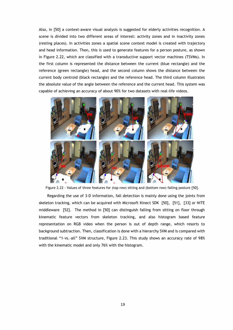
Figure 2.20 – Example where the classifier detects (left) open hand and (right) pointing gesture [44].
2.4. Fall Detection Sensing
There are multiple sensors with the purpose of detecting a fall. From wearable ones, like
accelerometers and gyroscopes that are attached to a belt [46], to external sensors such as
floor mounted sensors [47] and cameras. The latter is the research area with major
developments recently since older people may find wearable sensors intrusive and might forget
to use them.
There are quite a few cameras used in the literature, such as simple webcams [48],
omnidirectional cameras [49], and cameras with wide-angle lens [50]. Nevertheless, 2-D people
tracking is not enough for a robust fall detection, so a considerable number of studies ( [51],
[52], [34], [53] and [54]) have been published with the Kinect sensor.
Therefore the methods used to detect a fall can be grouped into 2-D and 3-D approaches.
In [48] a fall is detected by silhouette features (see Figure 2.21) and are posteriorly trained
with hidden Markov models for temporal pattern recognition. While Huang Y. [49] provides a
fall detection system through the angle and length variation of a body line, and also introduces
time Motion History Image to prevent false positives. A recognition occurs when those features
are above a threshold and enters in a decision tree mechanism. This system has an accuracy of
0.87 with a Kappa value of 0.75.
Figure 2.21 – (a)-(d) Some of the extracted features for fall activity. Each x-axis represents the frame
number. At frame 70 the subject fell and got up at frame 121, approximately [48].
19
Also, in [50] a context-aware visual analysis is suggested for elderly activities recognition. A
scene is divided into two different areas of interest: activity zones and in inactivity zones
(resting places). In activities zones a spatial scene context model is created with trajectory
and head information. Then, this is used to generate features for a person posture, as shown
in Figure 2.22, which are classified with a transductive support vector machines (TSVMs). In
the first column is represented the distance between the current (blue rectangle) and the
reference (green rectangle) head, and the second column shows the distance between the
current body centroid (black rectangle) and the reference head. The third column illustrates
the absolute value of the angle between the reference and the current head. This system was
capable of achieving an accuracy of about 90% for two datasets with real-life videos.
Regarding the use of 3-D information, fall detection is mainly done using the joints from
skeleton tracking, which can be acquired with Microsoft Kinect SDK [50], [51], [33] or NiTE
middleware [52]. The method in [50] can distinguish falling from sitting on floor through
kinematic feature vectors from skeleton tracking, and also histogram based feature
representation on RGB video when the person is out of depth range, which resorts to
background subtraction. Then, classification is done with a hierarchy SVM and is compared with
traditional “1-vs.-all” SVM structure, Figure 2.23. This study shows an accuracy rate of 98%
with the kinematic model and only 76% with the histogram.
Figure 2.22 - Values of three features for (top row) sitting and (bottom row) falling posture [50].
20
Figure 2.23 – (a)-(d) Confusion matrix of different activities (L1 to L5) recognition using hierarchy SVM
schema, and (e)-(h) “1-vs.-all” SVM classifier. (First row) Histogram-based, (a) and (e), and kinematic,
(b) and (f), model in normal case. (c) and (g) Histogram-based model with good illumination but out of
depth range. (d) and (h) kinematic model with low illumination and within depth range [51].
Kawatsu et al. [52] uses a simpler solution by calculating the distance from each joint to
the floor, and also the velocity of the joints. A picture is taken when the values are lower than
some threshold, so as to be sent to a phone via MMS. Similarly, Galatas et al. [34] uses a
threshold to detect a fallen skeleton, but it also captures the audio from Kinect to detect an
emergency with speech recognition.
Moreover, [53] shows an approach with multiple sensors. It combines the Kinect with an
accelerometer for occlusion situations. The ground plane is also detected using the RANSAC
algorithm, v-disparity images and Hough transform. Likewise, an alarm is detected when the
distance of the person centroid to the ground plane is bellow a settled threshold (see Figure
2.24).
Figure 2.24 – Centroid distance D to the ground plane for some daily activities [53].
At last, in [54] the depth data is processed in point clouds and the ground plane is extracted
using also the RANSAC algorithm to detect a fallen person, which happens when various layers
are classified positively. This research found that Histograms of Local Surface Normals (HLNS)
21
with a SVM classifier is the best feature-classifier combination for a fall system, of all the ones
evaluated.
2.5. Image Compression & Streaming
Mobile robots cannot use devices with high computational power due to its implications on
the batteries’ autonomy. So, one of the most relevant challenges in vision-guided mobiles
robots is the overload of the embedded processing unit, making real-time applications difficult
to achieve. Thus, there have been several studies on streaming compressed images, captured
from a robot, to an external device with better computational power. In this way, complex
vision processing algorithms, such as face recognition [55], can be used in mobile platforms.
Moreover, this type of systems allows remote teleoperation ( [56], [57]) and can also be useful
for person monitoring and vigilance ( [55], [58]). The Table 2.3 describes some of the
architectures used for image compression and streaming.
Table 2.3 – Examples of image compression schemes and streaming protocols.
Published
Reference
Compression
Scheme
Streaming
Protocol/Software
Image resolution
and frame rate Latency
[55]
Windows
Media Movie
9 (WMV9).
Microsoft Media
Server (MMS) via
Transmission
Control Protocol
(TCP).
320x240 with a
frame rate of 25
fps.
With a 33.6-kb/s
dial-up modem has a
time delay of 12s,
and using through
over 120-kb/s
bandwidth the delay
decreases to 8s.
[56] MPEG-4
codec.
User Datagram
Protocol (UDP). 640x480 at 25 fps.
Between 30 and
40ms.
[58] H.264/AVC
video coding.
GPRS/EDGE-GPRS
network.
320x240 at 10 fps
for PC-to-PC
scenario.
In a PC-to-PC
scenario it has a
latency of 1.21-
1.65s.
The number of research works with Kinect data streaming has rapidly increased too.
Nevertheless, applications developed up to today are usually focused in streaming the images
for 3-D videoconference [59], and real time 3-D scene reconstruction [60]. On the other hand,
Kinect streaming in robotics applications have been less noted. In the work [61] the sensor is
used for mobile robotic navigation and Simultaneous Localization and Mapping (SLAM).
However, due to the amount of Kinect data, the image processing is done onboard the robot
(laptop) and only the necessary data is sent over the network. Moreover, in [62] is presented a
remote teleoperation of a mobile robot, in which Kinect depth data is compressed with a
PieceWise Multi-Linear (PWML) approximation, and then is transmitted via UDP, allowing
sufficient situational awareness for teleoperation with low latency.
22
2.6. Conclusions
The outcome of this bibliographic survey allowed a better understanding of several
important approaches used up to today in robotic applications for home services, and
significantly influenced the selection of the algorithms implemented in this dissertation.
AAL robots have different functionalities such as schedule and medication reminder,
communication through video-call, person guiding, access to Internet services, therapy
activities, fall detection and other medical emergency situations.
In order to do all these tasks there are different sensors that can be equipped on these
robots. Simple sensors as laser range finders and ultrasonic sensors are vastly used for map
building and localization. These sensors can also be used for person localization since they can
estimate distances without high computation times.
The main vision sensors used are monocular and stereo cameras. Stereo-based approaches
obtain more robust results when compared to monocular approaches, as they allow depth
information which can be combined with color image. Thermal camera is also a good choice
since it is capable of good detection independently of the illumination conditions, and fusion
of thermal cameras and vision systems provide even better results. Nevertheless, thermal
cameras are more expensive than other sensors.
Moreover, several interesting algorithms for person following, gesture recognition, fall
detection and image streaming were presented. Regarding people detection, both face and
body detection/tracking have a large variety of algorithms. Viola-Jones is a popular method for
face detection due to its fast detection ability. Color segmentation is another widely method
used for face and body detection, and tracking as well, which accomplish good accuracy when
there are no significant changes of illumination. Furthermore, for sitting situations HOG-based
algorithms demonstrate good results, as it can handle partial occlusion.
People detection techniques, like optical-flow-based, are capable of detecting moving
objects even in the presence of camera motion. Whereas contour-based approaches describe
objects in a simpler and effective way, and the computational complexity is reduced.
Additionally, skeleton tracking from Kinect can be combined with different techniques capable
of robust body detection with low computational burden too.
Concerning gesture and fall recognition, all the described algorithms (whether using color
or depth information) exhibit notable results. Though, depth data methods show better
accuracy, even with insufficient illumination.
At last, there are still not many works about the use of image compressing and streaming
on mobile robots. Some of the research works described are capable of real-time applications
with different methods for compression and networks protocols for streaming, such as MPEG-4
and UDP, respectively.
In conclusion each approach presents advantages, disadvantages, and limitations.
Therefore, it is not easy to specify which algorithm presented in this survey is the best option.
23
On the other hand, an ideal AAL robot should not need beacons or artificial markers in the
house, and should use sensors that are not too expensive. Furthermore, people should not have
to wear any intrusive sensors to interact with the robot, and the navigation algorithm has to
be able to overcome unexpected obstacles and other people while following a person.
24
Chapter 3
System Overview
This chapter summarizes the system architecture developed. In which are described the
hardware components and the different algorithms implemented according to the dissertation
aims.
3.1. Hardware
In this work the RobVigil, an indoor surveillance robot developed by FEUP/INESC TEC, was
adapted with installation of a Kinect sensor in order to acquire robust information for person
tracking and human-robot interaction (see Figure 3.1). Also, a laptop was added to connect
with the Kinect due to its hardware requirements.
Figure 3.1- (Left) RobVigil robot, and (right) its features and sensors (adapted from [63]).
25
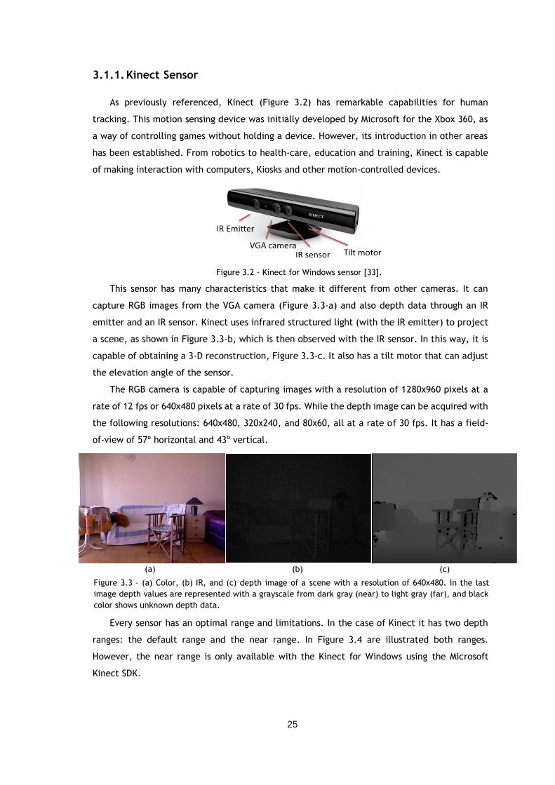
3.1.1. Kinect Sensor
As previously referenced, Kinect (Figure 3.2) has remarkable capabilities for human
tracking. This motion sensing device was initially developed by Microsoft for the Xbox 360, as
a way of controlling games without holding a device. However, its introduction in other areas
has been established. From robotics to health-care, education and training, Kinect is capable
of making interaction with computers, Kiosks and other motion-controlled devices.
Figure 3.2 - Kinect for Windows sensor [33].
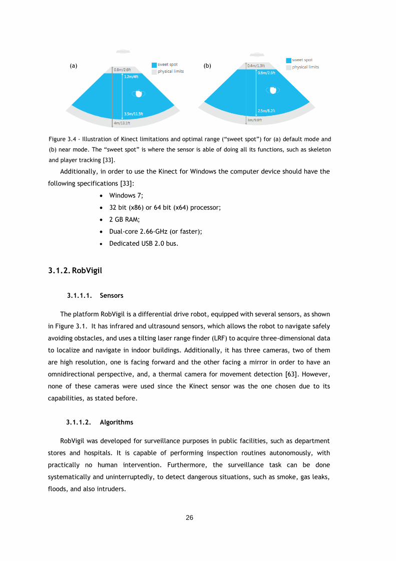
This sensor has many characteristics that make it different from other cameras. It can
capture RGB images from the VGA camera (Figure 3.3-a) and also depth data through an IR
emitter and an IR sensor. Kinect uses infrared structured light (with the IR emitter) to project
a scene, as shown in Figure 3.3-b, which is then observed with the IR sensor. In this way, it is
capable of obtaining a 3-D reconstruction, Figure 3.3-c. It also has a tilt motor that can adjust
the elevation angle of the sensor.
The RGB camera is capable of capturing images with a resolution of 1280x960 pixels at a
rate of 12 fps or 640x480 pixels at a rate of 30 fps. While the depth image can be acquired with
the following resolutions: 640x480, 320x240, and 80x60, all at a rate of 30 fps. It has a field-
of-view of 57º horizontal and 43º vertical.
Every sensor has an optimal range and limitations. In the case of Kinect it has two depth
ranges: the default range and the near range. In Figure 3.4 are illustrated both ranges.
However, the near range is only available with the Kinect for Windows using the Microsoft
Kinect SDK.
(a) (b) (c)
Figure 3.3 – (a) Color, (b) IR, and (c) depth image of a scene with a resolution of 640x480. In the last
image depth values are represented with a grayscale from dark gray (near) to light gray (far), and black
color shows unknown depth data.
26
Figure 3.4 - Illustration of Kinect limitations and optimal range (“sweet spot”) for (a) default mode and
(b) near mode. The “sweet spot” is where the sensor is able of doing all its functions, such as skeleton
and player tracking [33].
Additionally, in order to use the Kinect for Windows the computer device should have the
following specifications [33]:
Windows 7;
32 bit (x86) or 64 bit (x64) processor;
2 GB RAM;
Dual-core 2.66-GHz (or faster);
Dedicated USB 2.0 bus.
3.1.2. RobVigil
3.1.1.1. Sensors
The platform RobVigil is a differential drive robot, equipped with several sensors, as shown
in Figure 3.1. It has infrared and ultrasound sensors, which allows the robot to navigate safely
avoiding obstacles, and uses a tilting laser range finder (LRF) to acquire three-dimensional data
to localize and navigate in indoor buildings. Additionally, it has three cameras, two of them
are high resolution, one is facing forward and the other facing a mirror in order to have an
omnidirectional perspective, and, a thermal camera for movement detection [63]. However,
none of these cameras were used since the Kinect sensor was the one chosen due to its
capabilities, as stated before.
3.1.1.2. Algorithms
RobVigil was developed for surveillance purposes in public facilities, such as department
stores and hospitals. It is capable of performing inspection routines autonomously, with
practically no human intervention. Furthermore, the surveillance task can be done
systematically and uninterruptedly, to detect dangerous situations, such as smoke, gas leaks,
floods, and also intruders.
(a) (b)
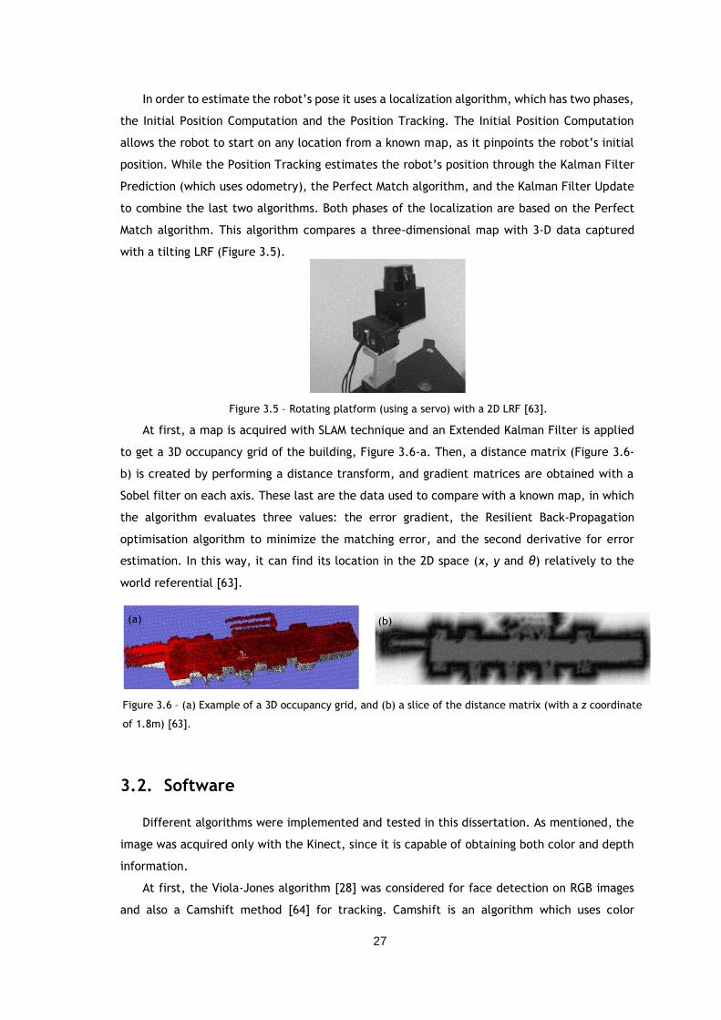
27
In order to estimate the robot’s pose it uses a localization algorithm, which has two phases,
the Initial Position Computation and the Position Tracking. The Initial Position Computation
allows the robot to start on any location from a known map, as it pinpoints the robot’s initial
position. While the Position Tracking estimates the robot’s position through the Kalman Filter
Prediction (which uses odometry), the Perfect Match algorithm, and the Kalman Filter Update
to combine the last two algorithms. Both phases of the localization are based on the Perfect
Match algorithm. This algorithm compares a three-dimensional map with 3-D data captured
with a tilting LRF (Figure 3.5).
Figure 3.5 – Rotating platform (using a servo) with a 2D LRF [63].
At first, a map is acquired with SLAM technique and an Extended Kalman Filter is applied
to get a 3D occupancy grid of the building, Figure 3.6-a. Then, a distance matrix (Figure 3.6-
b) is created by performing a distance transform, and gradient matrices are obtained with a
Sobel filter on each axis. These last are the data used to compare with a known map, in which
the algorithm evaluates three values: the error gradient, the Resilient Back-Propagation
optimisation algorithm to minimize the matching error, and the second derivative for error
estimation. In this way, it can find its location in the 2D space (x, y and θ) relatively to the
world referential [63].
3.2. Software
Different algorithms were implemented and tested in this dissertation. As mentioned, the
image was acquired only with the Kinect, since it is capable of obtaining both color and depth
information.
At first, the Viola-Jones algorithm [28] was considered for face detection on RGB images
and also a Camshift method [64] for tracking. Camshift is an algorithm which uses color
Figure 3.6 – (a) Example of a 3D occupancy grid, and (b) a slice of the distance matrix (with a z coordinate
of 1.8m) [63].
(b) (a)
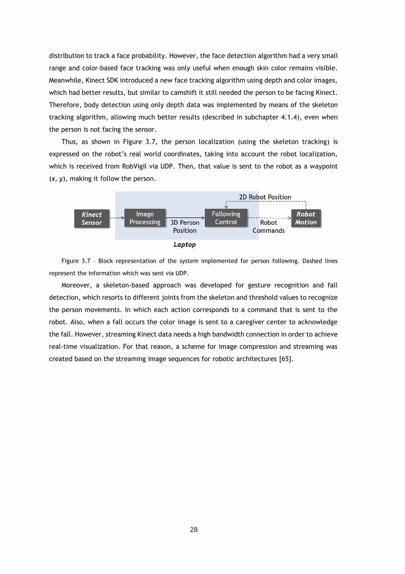
28
distribution to track a face probability. However, the face detection algorithm had a very small
range and color-based face tracking was only useful when enough skin color remains visible.
Meanwhile, Kinect SDK introduced a new face tracking algorithm using depth and color images,
which had better results, but similar to camshift it still needed the person to be facing Kinect.
Therefore, body detection using only depth data was implemented by means of the skeleton
tracking algorithm, allowing much better results (described in subchapter 4.1.4), even when
the person is not facing the sensor.
Thus, as shown in Figure 3.7, the person localization (using the skeleton tracking) is
expressed on the robot’s real world coordinates, taking into account the robot localization,
which is received from RobVigil via UDP. Then, that value is sent to the robot as a waypoint
(x, y), making it follow the person.
Figure 3.7 – Block representation of the system implemented for person following. Dashed lines
represent the information which was sent via UDP.
Moreover, a skeleton-based approach was developed for gesture recognition and fall
detection, which resorts to different joints from the skeleton and threshold values to recognize
the person movements. In which each action corresponds to a command that is sent to the
robot. Also, when a fall occurs the color image is sent to a caregiver center to acknowledge
the fall. However, streaming Kinect data needs a high bandwidth connection in order to achieve
real-time visualization. For that reason, a scheme for image compression and streaming was
created based on the streaming image sequences for robotic architectures [65].
29
Chapter 4
Vision System Framework
This chapter presents the different modules developed for the robot’s vision system. The
first section describes the algorithms implemented for people tracking, a face detection and
tracking technique, and the skeleton tracking. Followed by the presentation of the results for
each of the algorithms aforementioned. The following sections explain the methodology
employed for gesture recognition, fall detection, and image compression and streaming.
Finally, some notes on the database creation are presented.
4.1. People Detection & Tracking
As mentioned, for people detection and tracking were implemented two different
approaches in C++. OpenCV library [66] was selected for face detection and tracking using RGB
image. While for body detection with depth image were used some specific libraries for Kinect
and other depth sensors: Microsoft Kinect SDK, OpenNI library and NiTE middleware.
4.1.1. OpenCV Face Detection & Tracking
The face detection technique chosen was the Viola-Jones algorithm since it is capable of
processing images extremely fast while achieving high detection rates. It uses Haar-like
features, which are based on Haar wavelets. They are simply a pair of adjacent rectangles, one
light and one dark, representing a single wavelength square wave. Though, these features use
several rectangle combinations (with different sizes and positions) better suited for a human
face, as shown in Figure 4.1. When the subtraction between the white section and the gray
section of the rectangle is above a settled threshold, the feature is present.
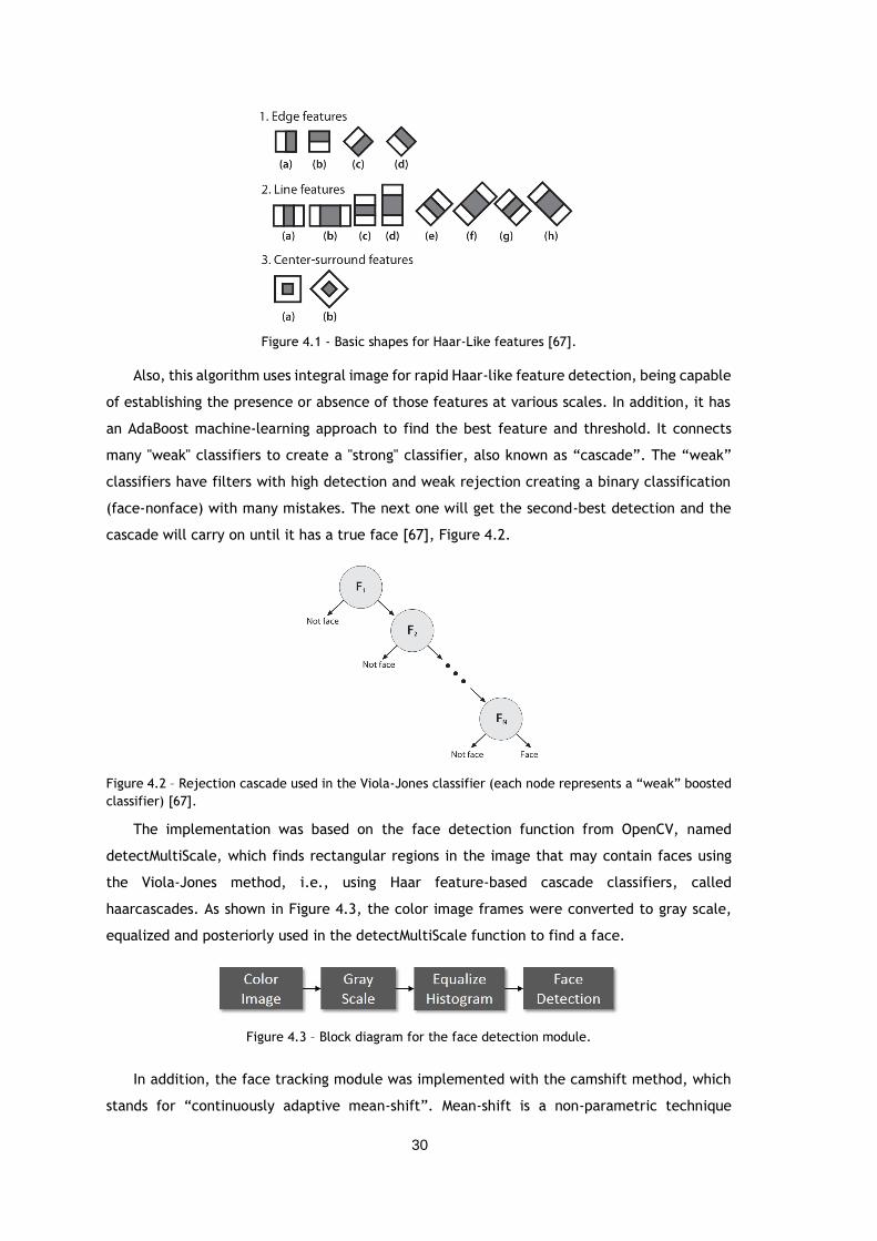
30
Figure 4.1 - Basic shapes for Haar-Like features [67].
Also, this algorithm uses integral image for rapid Haar-like feature detection, being capable
of establishing the presence or absence of those features at various scales. In addition, it has
an AdaBoost machine-learning approach to find the best feature and threshold. It connects
many "weak" classifiers to create a "strong" classifier, also known as “cascade”. The “weak”
classifiers have filters with high detection and weak rejection creating a binary classification
(face-nonface) with many mistakes. The next one will get the second-best detection and the
cascade will carry on until it has a true face [67], Figure 4.2.
Figure 4.2 – Rejection cascade used in the Viola-Jones classifier (each node represents a “weak” boosted
classifier) [67].
The implementation was based on the face detection function from OpenCV, named
detectMultiScale, which finds rectangular regions in the image that may contain faces using
the Viola-Jones method, i.e., using Haar feature-based cascade classifiers, called
haarcascades. As shown in Figure 4.3, the color image frames were converted to gray scale,
equalized and posteriorly used in the detectMultiScale function to find a face.
Figure 4.3 – Block diagram for the face detection module.
In addition, the face tracking module was implemented with the camshift method, which
stands for “continuously adaptive mean-shift”. Mean-shift is a non-parametric technique
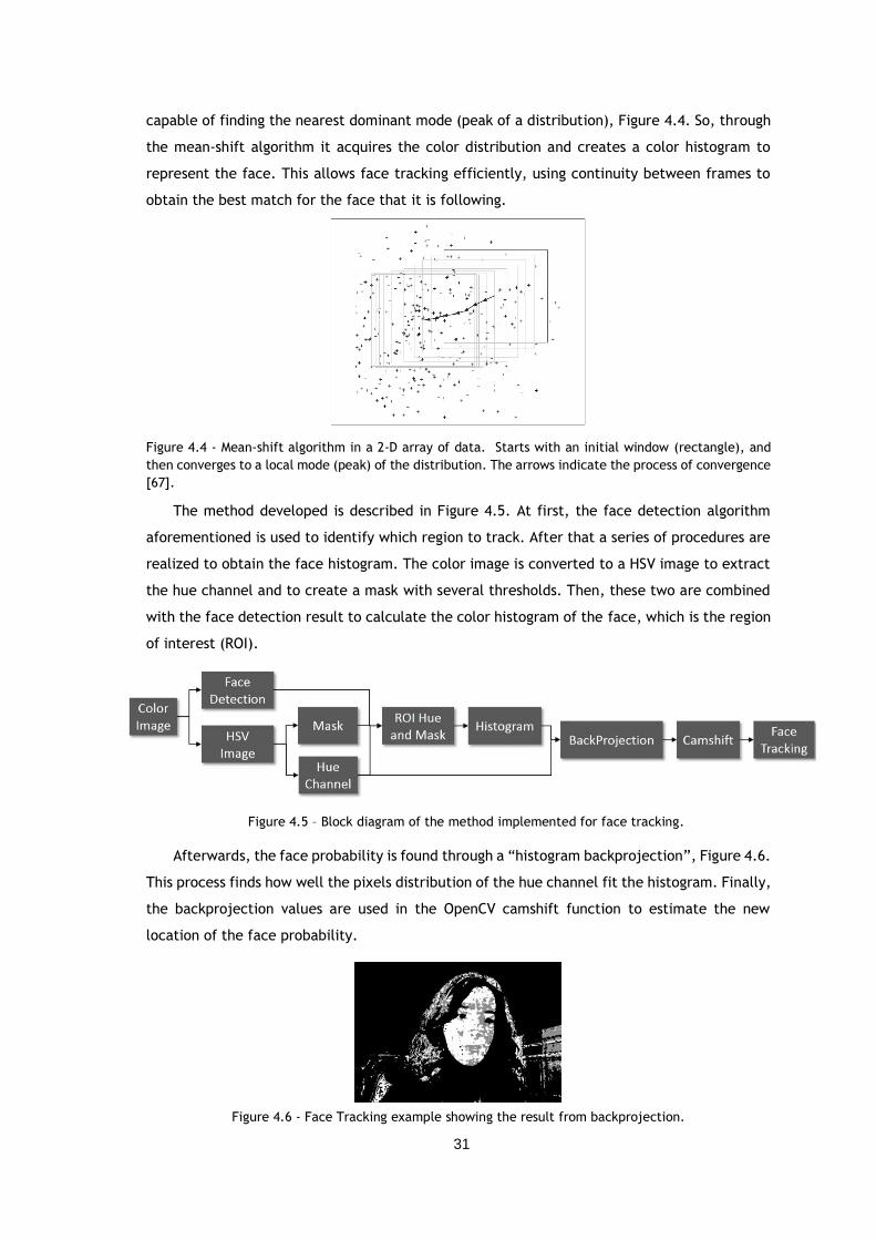
31
capable of finding the nearest dominant mode (peak of a distribution), Figure 4.4. So, through
the mean-shift algorithm it acquires the color distribution and creates a color histogram to
represent the face. This allows face tracking efficiently, using continuity between frames to
obtain the best match for the face that it is following.
Figure 4.4 - Mean-shift algorithm in a 2-D array of data. Starts with an initial window (rectangle), and
then converges to a local mode (peak) of the distribution. The arrows indicate the process of convergence
[67].
The method developed is described in Figure 4.5. At first, the face detection algorithm
aforementioned is used to identify which region to track. After that a series of procedures are
realized to obtain the face histogram. The color image is converted to a HSV image to extract
the hue channel and to create a mask with several thresholds. Then, these two are combined
with the face detection result to calculate the color histogram of the face, which is the region
of interest (ROI).
Afterwards, the face probability is found through a “histogram backprojection”, Figure 4.6.
This process finds how well the pixels distribution of the hue channel fit the histogram. Finally,
the backprojection values are used in the OpenCV camshift function to estimate the new
location of the face probability.
Figure 4.6 - Face Tracking example showing the result from backprojection.
Figure 4.5 – Block diagram of the method implemented for face tracking.
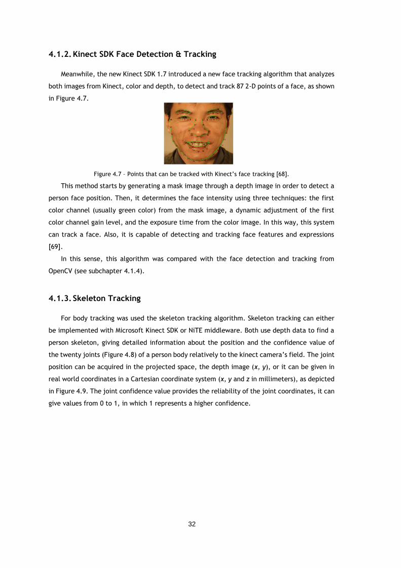
32
4.1.2. Kinect SDK Face Detection & Tracking
Meanwhile, the new Kinect SDK 1.7 introduced a new face tracking algorithm that analyzes
both images from Kinect, color and depth, to detect and track 87 2-D points of a face, as shown
in Figure 4.7.
Figure 4.7 – Points that can be tracked with Kinect’s face tracking [68].
This method starts by generating a mask image through a depth image in order to detect a
person face position. Then, it determines the face intensity using three techniques: the first
color channel (usually green color) from the mask image, a dynamic adjustment of the first
color channel gain level, and the exposure time from the color image. In this way, this system
can track a face. Also, it is capable of detecting and tracking face features and expressions
[69].
In this sense, this algorithm was compared with the face detection and tracking from
OpenCV (see subchapter 4.1.4).
4.1.3. Skeleton Tracking
For body tracking was used the skeleton tracking algorithm. Skeleton tracking can either
be implemented with Microsoft Kinect SDK or NiTE middleware. Both use depth data to find a
person skeleton, giving detailed information about the position and the confidence value of
the twenty joints (Figure 4.8) of a person body relatively to the kinect camera’s field. The joint
position can be acquired in the projected space, the depth image (x, y), or it can be given in
real world coordinates in a Cartesian coordinate system (x, y and z in millimeters), as depicted
in Figure 4.9. The joint confidence value provides the reliability of the joint coordinates, it can
give values from 0 to 1, in which 1 represents a higher confidence.
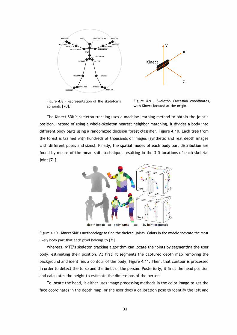
33
The Kinect SDK’s skeleton tracking uses a machine learning method to obtain the joint’s
position. Instead of using a whole-skeleton nearest neighbor matching, it divides a body into
different body parts using a randomized decision forest classifier, Figure 4.10. Each tree from
the forest is trained with hundreds of thousands of images (synthetic and real depth images
with different poses and sizes). Finally, the spatial modes of each body part distribution are
found by means of the mean-shift technique, resulting in the 3-D locations of each skeletal
joint [71].
Figure 4.10 – Kinect SDK’s methodology to find the skeletal joints. Colors in the middle indicate the most
likely body part that each pixel belongs to [71].
Whereas, NiTE’s skeleton tracking algorithm can locate the joints by segmenting the user
body, estimating their position. At first, it segments the captured depth map removing the
background and identifies a contour of the body, Figure 4.11. Then, that contour is processed
in order to detect the torso and the limbs of the person. Posteriorly, it finds the head position
and calculates the height to estimate the dimensions of the person.
To locate the head, it either uses image processing methods in the color image to get the
face coordinates in the depth map, or the user does a calibration pose to identify the left and
Figure 4.8 – Representation of the skeleton’s
20 joints [70].
Figure 4.9 - Skeleton Cartesian coordinates,
with Kinect located at the origin.
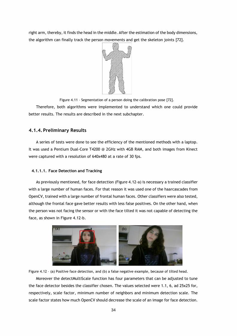
34
right arm, thereby, it finds the head in the middle. After the estimation of the body dimensions,
the algorithm can finally track the person movements and get the skeleton joints [72].
Figure 4.11 – Segmentation of a person doing the calibration pose [72].
Therefore, both algorithms were implemented to understand which one could provide
better results. The results are described in the next subchapter.
4.1.4. Preliminary Results
A series of tests were done to see the efficiency of the mentioned methods with a laptop.
It was used a Pentium Dual-Core T4200 @ 2GHz with 4GB RAM, and both images from Kinect
were captured with a resolution of 640x480 at a rate of 30 fps.
4.1.1.1. Face Detection and Tracking
As previously mentioned, for face detection (Figure 4.12-a) is necessary a trained classifier
with a large number of human faces. For that reason it was used one of the haarcascades from
OpenCV, trained with a large number of frontal human faces. Other classifiers were also tested,
although the frontal face gave better results with less false positives. On the other hand, when
the person was not facing the sensor or with the face tilted it was not capable of detecting the
face, as shown in Figure 4.12-b.
Figure 4.12 – (a) Positive face detection, and (b) a false negative example, because of tilted head.
Moreover the detectMultiScale function has four parameters that can be adjusted to tune
the face detector besides the classifier chosen. The values selected were 1.1, 6, ad 25x25 for,
respectively, scale factor, minimum number of neighbors and minimum detection scale. The
scale factor states how much OpenCV should decrease the scale of an image for face detection.
(b) (a)
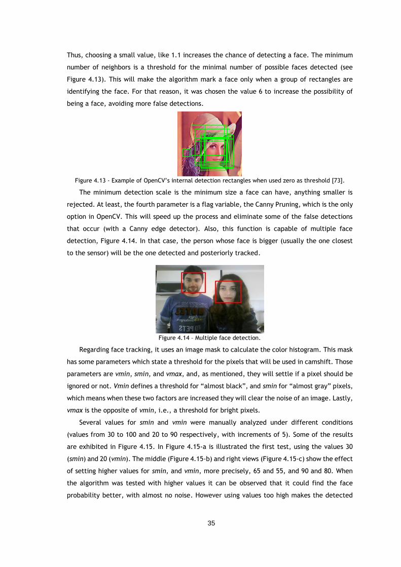
35
Thus, choosing a small value, like 1.1 increases the chance of detecting a face. The minimum
number of neighbors is a threshold for the minimal number of possible faces detected (see
Figure 4.13). This will make the algorithm mark a face only when a group of rectangles are
identifying the face. For that reason, it was chosen the value 6 to increase the possibility of
being a face, avoiding more false detections.
Figure 4.13 - Example of OpenCV’s internal detection rectangles when used zero as threshold [73].
The minimum detection scale is the minimum size a face can have, anything smaller is
rejected. At least, the fourth parameter is a flag variable, the Canny Pruning, which is the only
option in OpenCV. This will speed up the process and eliminate some of the false detections
that occur (with a Canny edge detector). Also, this function is capable of multiple face
detection, Figure 4.14. In that case, the person whose face is bigger (usually the one closest
to the sensor) will be the one detected and posteriorly tracked.
Figure 4.14 – Multiple face detection.
Regarding face tracking, it uses an image mask to calculate the color histogram. This mask
has some parameters which state a threshold for the pixels that will be used in camshift. Those
parameters are vmin, smin, and vmax, and, as mentioned, they will settle if a pixel should be
ignored or not. Vmin defines a threshold for “almost black”, and smin for “almost gray” pixels,
which means when these two factors are increased they will clear the noise of an image. Lastly,
vmax is the opposite of vmin, i.e., a threshold for bright pixels.
Several values for smin and vmin were manually analyzed under different conditions
(values from 30 to 100 and 20 to 90 respectively, with increments of 5). Some of the results
are exhibited in Figure 4.15. In Figure 4.15-a is illustrated the first test, using the values 30
(smin) and 20 (vmin). The middle (Figure 4.15-b) and right views (Figure 4.15-c) show the effect
of setting higher values for smin, and vmin, more precisely, 65 and 55, and 90 and 80. When
the algorithm was tested with higher values it can be observed that it could find the face
probability better, with almost no noise. However using values too high makes the detected
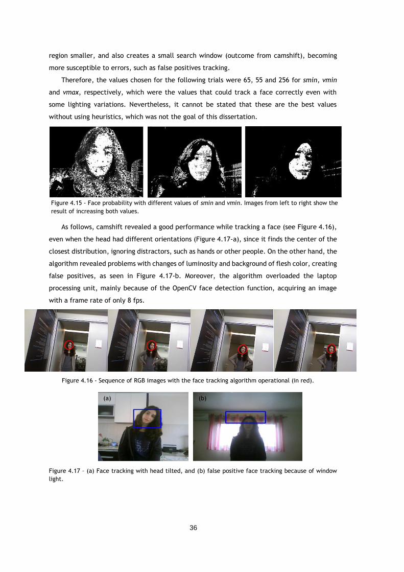
36
region smaller, and also creates a small search window (outcome from camshift), becoming
more susceptible to errors, such as false positives tracking.
Therefore, the values chosen for the following trials were 65, 55 and 256 for smin, vmin
and vmax, respectively, which were the values that could track a face correctly even with
some lighting variations. Nevertheless, it cannot be stated that these are the best values
without using heuristics, which was not the goal of this dissertation.
As follows, camshift revealed a good performance while tracking a face (see Figure 4.16),
even when the head had different orientations (Figure 4.17-a), since it finds the center of the
closest distribution, ignoring distractors, such as hands or other people. On the other hand, the
algorithm revealed problems with changes of luminosity and background of flesh color, creating
false positives, as seen in Figure 4.17-b. Moreover, the algorithm overloaded the laptop
processing unit, mainly because of the OpenCV face detection function, acquiring an image
with a frame rate of only 8 fps.
Figure 4.17 – (a) Face tracking with head tilted, and (b) false positive face tracking because of window
light.
Figure 4.16 - Sequence of RGB images with the face tracking algorithm operational (in red).
Figure 4.15 - Face probability with different values of smin and vmin. Images from left to right show the
result of increasing both values.
(b) (a)
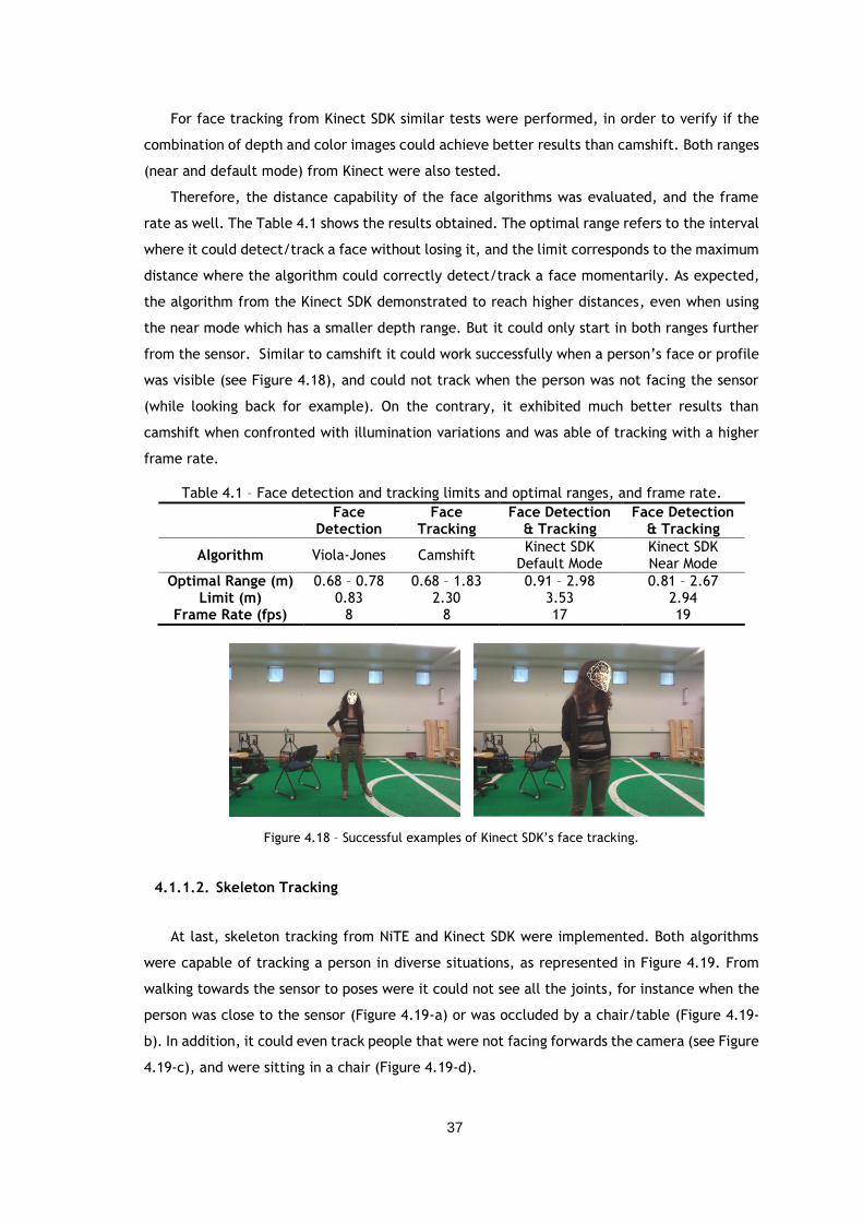
37
For face tracking from Kinect SDK similar tests were performed, in order to verify if the
combination of depth and color images could achieve better results than camshift. Both ranges
(near and default mode) from Kinect were also tested.
Therefore, the distance capability of the face algorithms was evaluated, and the frame
rate as well. The Table 4.1 shows the results obtained. The optimal range refers to the interval
where it could detect/track a face without losing it, and the limit corresponds to the maximum
distance where the algorithm could correctly detect/track a face momentarily. As expected,
the algorithm from the Kinect SDK demonstrated to reach higher distances, even when using
the near mode which has a smaller depth range. But it could only start in both ranges further
from the sensor. Similar to camshift it could work successfully when a person’s face or profile
was visible (see Figure 4.18), and could not track when the person was not facing the sensor
(while looking back for example). On the contrary, it exhibited much better results than
camshift when confronted with illumination variations and was able of tracking with a higher
frame rate.
Table 4.1 – Face detection and tracking limits and optimal ranges, and frame rate.
Face Detection
Face Tracking
Face Detection & Tracking
Face Detection & Tracking
Algorithm Viola-Jones Camshift Kinect SDK
Default Mode Kinect SDK Near Mode
Optimal Range (m) 0.68 – 0.78 0.68 – 1.83 0.91 – 2.98 0.81 – 2.67 Limit (m) 0.83 2.30 3.53 2.94
Frame Rate (fps) 8 8 17 19
Figure 4.18 – Successful examples of Kinect SDK’s face tracking.
4.1.1.2. Skeleton Tracking
At last, skeleton tracking from NiTE and Kinect SDK were implemented. Both algorithms
were capable of tracking a person in diverse situations, as represented in Figure 4.19. From
walking towards the sensor to poses were it could not see all the joints, for instance when the
person was close to the sensor (Figure 4.19-a) or was occluded by a chair/table (Figure 4.19-
b). In addition, it could even track people that were not facing forwards the camera (see Figure
4.19-c), and were sitting in a chair (Figure 4.19-d).
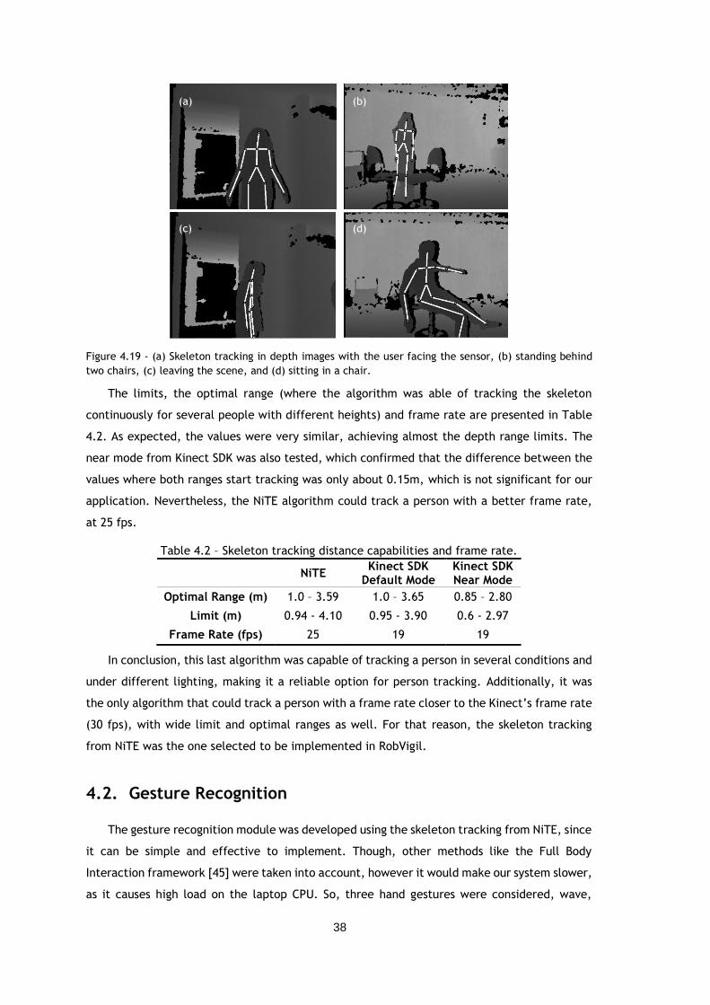
38
Figure 4.19 - (a) Skeleton tracking in depth images with the user facing the sensor, (b) standing behind
two chairs, (c) leaving the scene, and (d) sitting in a chair.
The limits, the optimal range (where the algorithm was able of tracking the skeleton
continuously for several people with different heights) and frame rate are presented in Table
4.2. As expected, the values were very similar, achieving almost the depth range limits. The
near mode from Kinect SDK was also tested, which confirmed that the difference between the
values where both ranges start tracking was only about 0.15m, which is not significant for our
application. Nevertheless, the NiTE algorithm could track a person with a better frame rate,
at 25 fps.
Table 4.2 – Skeleton tracking distance capabilities and frame rate.
NiTE Kinect SDK
Default Mode Kinect SDK Near Mode
Optimal Range (m) 1.0 – 3.59 1.0 – 3.65 0.85 – 2.80
Limit (m) 0.94 - 4.10 0.95 - 3.90 0.6 - 2.97
Frame Rate (fps) 25 19 19
In conclusion, this last algorithm was capable of tracking a person in several conditions and
under different lighting, making it a reliable option for person tracking. Additionally, it was
the only algorithm that could track a person with a frame rate closer to the Kinect’s frame rate
(30 fps), with wide limit and optimal ranges as well. For that reason, the skeleton tracking
from NiTE was the one selected to be implemented in RobVigil.
4.2. Gesture Recognition
The gesture recognition module was developed using the skeleton tracking from NiTE, since
it can be simple and effective to implement. Though, other methods like the Full Body
Interaction framework [45] were taken into account, however it would make our system slower,
as it causes high load on the laptop CPU. So, three hand gestures were considered, wave,
(a) (b)
(c) (d)
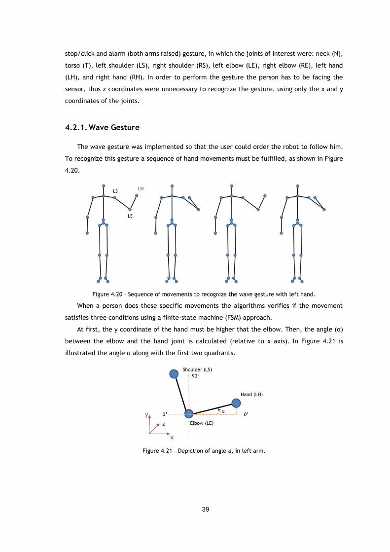
39
stop/click and alarm (both arms raised) gesture, in which the joints of interest were: neck (N),
torso (T), left shoulder (LS), right shoulder (RS), left elbow (LE), right elbow (RE), left hand
(LH), and right hand (RH). In order to perform the gesture the person has to be facing the
sensor, thus z coordinates were unnecessary to recognize the gesture, using only the x and y
coordinates of the joints.
4.2.1. Wave Gesture
The wave gesture was implemented so that the user could order the robot to follow him.
To recognize this gesture a sequence of hand movements must be fulfilled, as shown in Figure
4.20.
Figure 4.20 – Sequence of movements to recognize the wave gesture with left hand.
When a person does these specific movements the algorithms verifies if the movement
satisfies three conditions using a finite-state machine (FSM) approach.
At first, the y coordinate of the hand must be higher that the elbow. Then, the angle (α)
between the elbow and the hand joint is calculated (relative to x axis). In Figure 4.21 is
illustrated the angle α along with the first two quadrants.
Figure 4.21 – Depiction of angle α, in left arm.
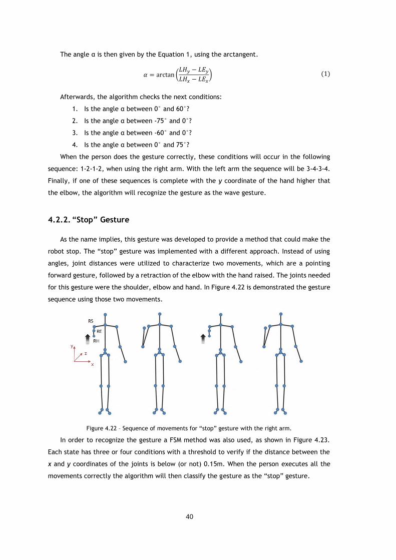
40
The angle α is then given by the Equation 1, using the arctangent.
𝛼 = arctan (𝐿𝐻𝑦 − 𝐿𝐸𝑦
𝐿𝐻𝑥 − 𝐿𝐸𝑥)
Afterwards, the algorithm checks the next conditions:
1. Is the angle α between 0° and 60°?
2. Is the angle α between -75° and 0°?
3. Is the angle α between -60° and 0°?
4. Is the angle α between 0° and 75°?
When the person does the gesture correctly, these conditions will occur in the following
sequence: 1-2-1-2, when using the right arm. With the left arm the sequence will be 3-4-3-4.
Finally, if one of these sequences is complete with the y coordinate of the hand higher that
the elbow, the algorithm will recognize the gesture as the wave gesture.
4.2.2. “Stop” Gesture
As the name implies, this gesture was developed to provide a method that could make the
robot stop. The “stop” gesture was implemented with a different approach. Instead of using
angles, joint distances were utilized to characterize two movements, which are a pointing
forward gesture, followed by a retraction of the elbow with the hand raised. The joints needed
for this gesture were the shoulder, elbow and hand. In Figure 4.22 is demonstrated the gesture
sequence using those two movements.
Figure 4.22 – Sequence of movements for “stop” gesture with the right arm.
In order to recognize the gesture a FSM method was also used, as shown in Figure 4.23.
Each state has three or four conditions with a threshold to verify if the distance between the
x and y coordinates of the joints is below (or not) 0.15m. When the person executes all the
movements correctly the algorithm will then classify the gesture as the “stop” gesture.
(1)
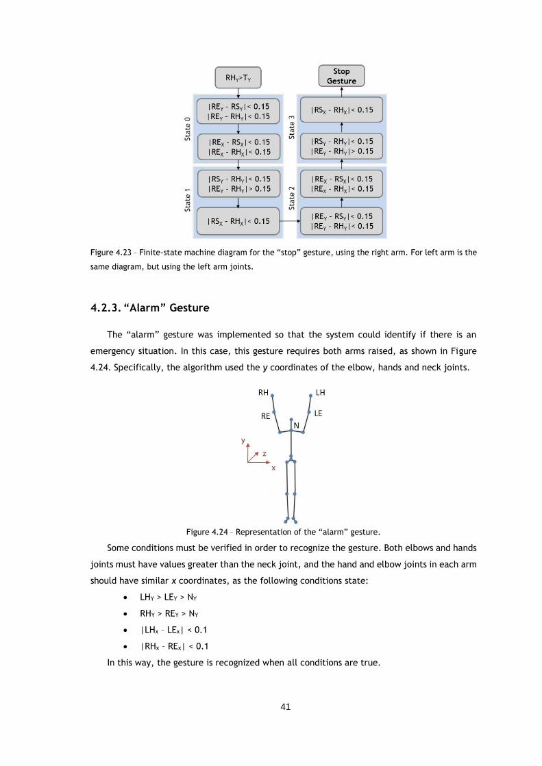
41
Figure 4.23 – Finite-state machine diagram for the “stop” gesture, using the right arm. For left arm is the
same diagram, but using the left arm joints.
4.2.3. “Alarm” Gesture
The “alarm” gesture was implemented so that the system could identify if there is an
emergency situation. In this case, this gesture requires both arms raised, as shown in Figure
4.24. Specifically, the algorithm used the y coordinates of the elbow, hands and neck joints.
Figure 4.24 – Representation of the “alarm” gesture.
Some conditions must be verified in order to recognize the gesture. Both elbows and hands
joints must have values greater than the neck joint, and the hand and elbow joints in each arm
should have similar x coordinates, as the following conditions state:
LHY > LEY > NY
RHY > REY > NY
|LHx – LEx| < 0.1
|RHx – REx| < 0.1
In this way, the gesture is recognized when all conditions are true.
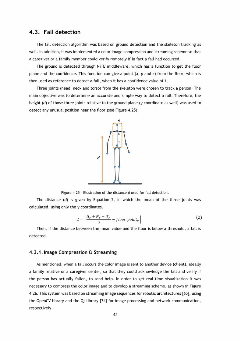
42
4.3. Fall detection
The fall detection algorithm was based on ground detection and the skeleton tracking as
well. In addition, it was implemented a color image compression and streaming scheme so that
a caregiver or a family member could verify remotely if in fact a fall had occurred.
The ground is detected through NiTE middleware, which has a function to get the floor
plane and the confidence. This function can give a point (x, y and z) from the floor, which is
then used as reference to detect a fall, when it has a confidence value of 1.
Three joints (head, neck and torso) from the skeleton were chosen to track a person. The
main objective was to determine an accurate and simple way to detect a fall. Therefore, the
height (d) of those three joints relative to the ground plane (y coordinate as well) was used to
detect any unusual position near the floor (see Figure 4.25).
Figure 4.25 – Illustration of the distance d used for fall detection.
The distance (d) is given by Equation 2, in which the mean of the three joints was
calculated, using only the y coordinates.
𝑑 = | 𝐻𝑦 + 𝑁𝑦 + 𝑇𝑦
3− 𝑓𝑙𝑜𝑜𝑟_𝑝𝑜𝑖𝑛𝑡𝑦 |
Then, if the distance between the mean value and the floor is below a threshold, a fall is
detected.
4.3.1. Image Compression & Streaming
As mentioned, when a fall occurs the color image is sent to another device (client), ideally
a family relative or a caregiver center, so that they could acknowledge the fall and verify if
the person has actually fallen, to send help. In order to get real-time visualization it was
necessary to compress the color image and to develop a streaming scheme, as shown in Figure
4.26. This system was based on streaming image sequences for robotic architectures [65], using
the OpenCV library and the Qt library [74] for image processing and network communication,
respectively.
(2)
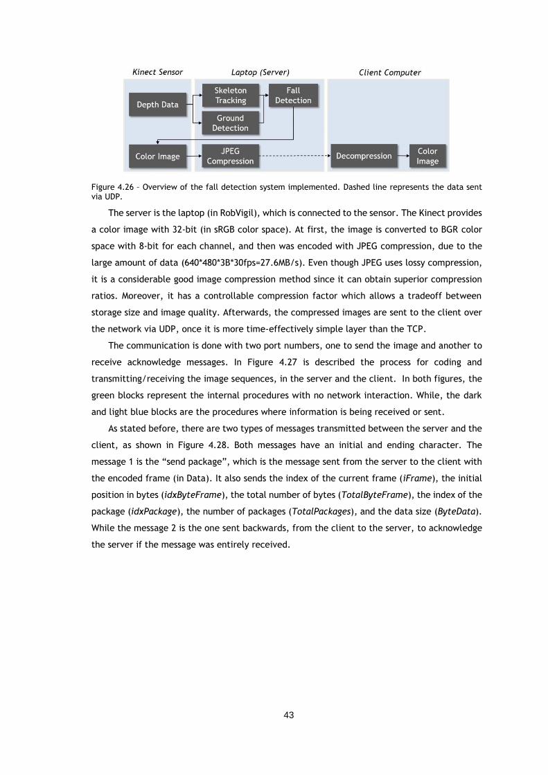
43
Figure 4.26 – Overview of the fall detection system implemented. Dashed line represents the data sent via UDP.
The server is the laptop (in RobVigil), which is connected to the sensor. The Kinect provides
a color image with 32-bit (in sRGB color space). At first, the image is converted to BGR color
space with 8-bit for each channel, and then was encoded with JPEG compression, due to the
large amount of data (640*480*3B*30fps=27.6MB/s). Even though JPEG uses lossy compression,
it is a considerable good image compression method since it can obtain superior compression
ratios. Moreover, it has a controllable compression factor which allows a tradeoff between
storage size and image quality. Afterwards, the compressed images are sent to the client over
the network via UDP, once it is more time-effectively simple layer than the TCP.
The communication is done with two port numbers, one to send the image and another to
receive acknowledge messages. In Figure 4.27 is described the process for coding and
transmitting/receiving the image sequences, in the server and the client. In both figures, the
green blocks represent the internal procedures with no network interaction. While, the dark
and light blue blocks are the procedures where information is being received or sent.
As stated before, there are two types of messages transmitted between the server and the
client, as shown in Figure 4.28. Both messages have an initial and ending character. The
message 1 is the “send package”, which is the message sent from the server to the client with
the encoded frame (in Data). It also sends the index of the current frame (iFrame), the initial
position in bytes (idxByteFrame), the total number of bytes (TotalByteFrame), the index of the
package (idxPackage), the number of packages (TotalPackages), and the data size (ByteData).
While the message 2 is the one sent backwards, from the client to the server, to acknowledge
the server if the message was entirely received.
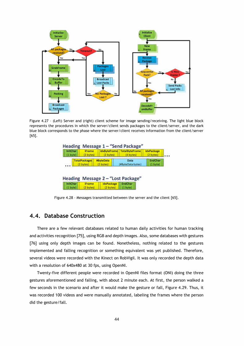
44
Figure 4.27 – (Left) Server and (right) client scheme for image sending/receiving. The light blue block
represents the procedures in which the server/client sends packages to the client/server, and the dark
blue block corresponds to the phase where the server/client receives information from the client/server
[65].
Figure 4.28 - Messages transmitted between the server and the client [65].
4.4. Database Construction
There are a few relevant databases related to human daily activities for human tracking
and activities recognition [75], using RGB and depth images. Also, some databases with gestures
[76] using only depth images can be found. Nonetheless, nothing related to the gestures
implemented and falling recognition or something equivalent was yet published. Therefore,
several videos were recorded with the Kinect on RobVigil. It was only recorded the depth data
with a resolution of 640x480 at 30 fps, using OpenNI.
Twenty-five different people were recorded in OpenNI files format (ONI) doing the three
gestures aforementioned and falling, with about 2 minute each. At first, the person walked a
few seconds in the scenario and after it would make the gesture or fall, Figure 4.29. Thus, it
was recorded 100 videos and were manually annotated, labeling the frames where the person
did the gesture/fall.
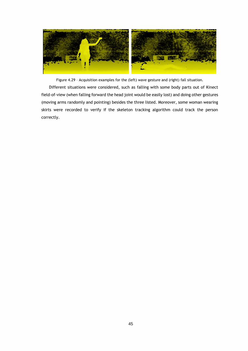
45
Figure 4.29 – Acquisition examples for the (left) wave gesture and (right) fall situation.
Different situations were considered, such as falling with some body parts out of Kinect
field-of-view (when falling forward the head joint would be easily lost) and doing other gestures
(moving arms randomly and pointing) besides the three listed. Moreover, some woman wearing
skirts were recorded to verify if the skeleton tracking algorithm could track the person
correctly.
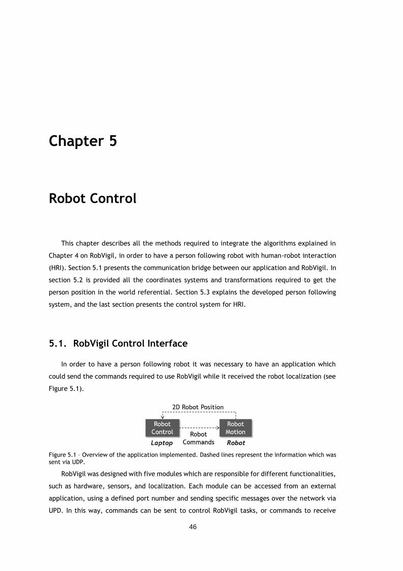
46
Chapter 5
Robot Control
This chapter describes all the methods required to integrate the algorithms explained in
Chapter 4 on RobVigil, in order to have a person following robot with human-robot interaction
(HRI). Section 5.1 presents the communication bridge between our application and RobVigil. In
section 5.2 is provided all the coordinates systems and transformations required to get the
person position in the world referential. Section 5.3 explains the developed person following
system, and the last section presents the control system for HRI.
5.1. RobVigil Control Interface
In order to have a person following robot it was necessary to have an application which
could send the commands required to use RobVigil while it received the robot localization (see
Figure 5.1).
Figure 5.1 – Overview of the application implemented. Dashed lines represent the information which was
sent via UDP.
RobVigil was designed with five modules which are responsible for different functionalities,
such as hardware, sensors, and localization. Each module can be accessed from an external
application, using a defined port number and sending specific messages over the network via
UPD. In this way, commands can be sent to control RobVigil tasks, or commands to receive
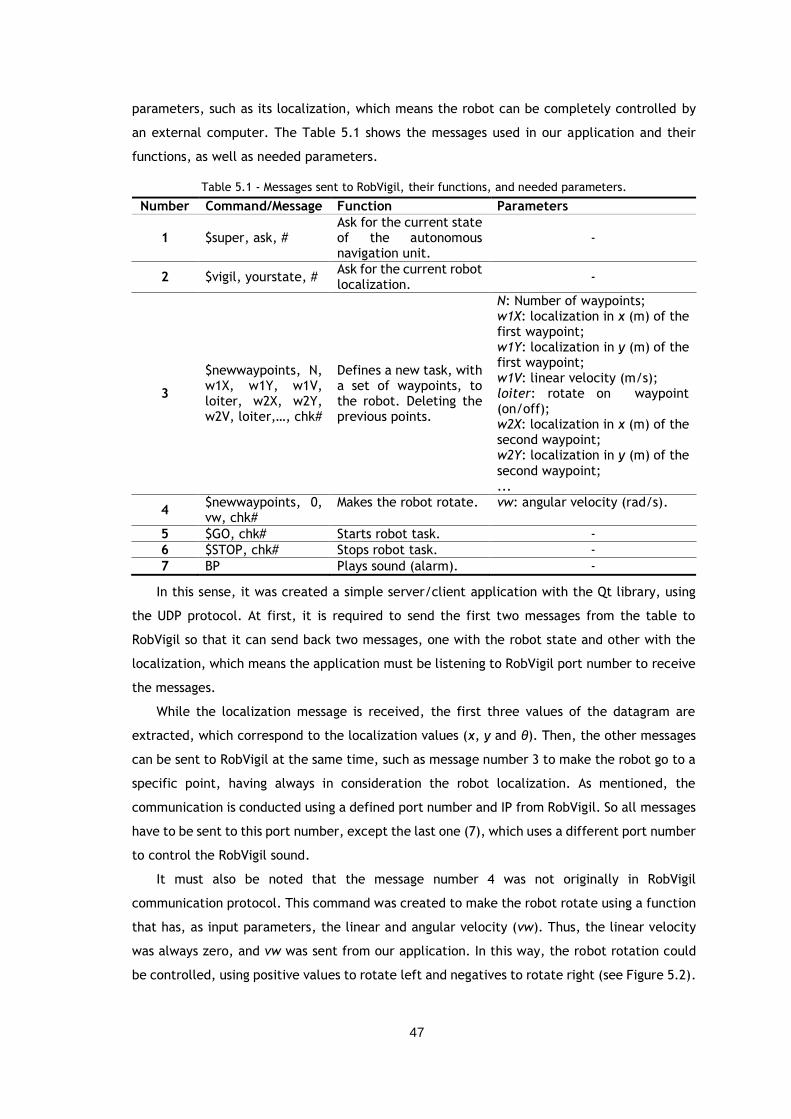
47
parameters, such as its localization, which means the robot can be completely controlled by
an external computer. The Table 5.1 shows the messages used in our application and their
functions, as well as needed parameters.
Table 5.1 - Messages sent to RobVigil, their functions, and needed parameters.
Number Command/Message Function Parameters
1 $super, ask, # Ask for the current state of the autonomous navigation unit.
-
2 $vigil, yourstate, # Ask for the current robot localization.
-
3
$newwaypoints, N, w1X, w1Y, w1V, loiter, w2X, w2Y, w2V, loiter,…, chk#
Defines a new task, with a set of waypoints, to the robot. Deleting the previous points.
N: Number of waypoints; w1X: localization in x (m) of the first waypoint; w1Y: localization in y (m) of the first waypoint; w1V: linear velocity (m/s); loiter: rotate on waypoint (on/off); w2X: localization in x (m) of the second waypoint; w2Y: localization in y (m) of the
second waypoint; ...
4 $newwaypoints, 0, vw, chk#
Makes the robot rotate. vw: angular velocity (rad/s).
5 $GO, chk# Starts robot task. -
6 $STOP, chk# Stops robot task. -
7 BP Plays sound (alarm). -
In this sense, it was created a simple server/client application with the Qt library, using
the UDP protocol. At first, it is required to send the first two messages from the table to
RobVigil so that it can send back two messages, one with the robot state and other with the
localization, which means the application must be listening to RobVigil port number to receive
the messages.
While the localization message is received, the first three values of the datagram are
extracted, which correspond to the localization values (x, y and θ). Then, the other messages
can be sent to RobVigil at the same time, such as message number 3 to make the robot go to a
specific point, having always in consideration the robot localization. As mentioned, the
communication is conducted using a defined port number and IP from RobVigil. So all messages
have to be sent to this port number, except the last one (7), which uses a different port number
to control the RobVigil sound.
It must also be noted that the message number 4 was not originally in RobVigil
communication protocol. This command was created to make the robot rotate using a function
that has, as input parameters, the linear and angular velocity (vw). Thus, the linear velocity
was always zero, and vw was sent from our application. In this way, the robot rotation could
be controlled, using positive values to rotate left and negatives to rotate right (see Figure 5.2).
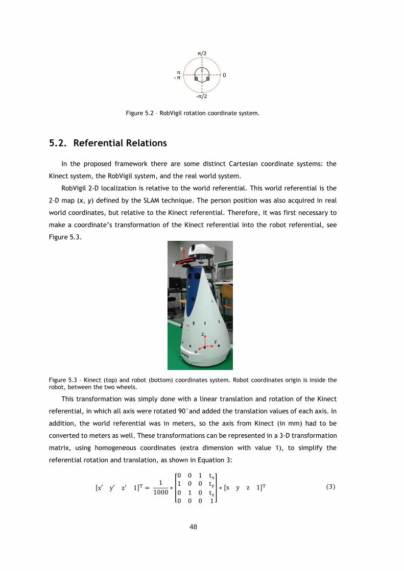
48
Figure 5.2 – RobVigil rotation coordinate system.
5.2. Referential Relations
In the proposed framework there are some distinct Cartesian coordinate systems: the
Kinect system, the RobVigil system, and the real world system.
RobVigil 2-D localization is relative to the world referential. This world referential is the
2-D map (x, y) defined by the SLAM technique. The person position was also acquired in real
world coordinates, but relative to the Kinect referential. Therefore, it was first necessary to
make a coordinate’s transformation of the Kinect referential into the robot referential, see
Figure 5.3.
Figure 5.3 – Kinect (top) and robot (bottom) coordinates system. Robot coordinates origin is inside the robot, between the two wheels.
This transformation was simply done with a linear translation and rotation of the Kinect
referential, in which all axis were rotated 90°and added the translation values of each axis. In
addition, the world referential was in meters, so the axis from Kinect (in mm) had to be
converted to meters as well. These transformations can be represented in a 3-D transformation
matrix, using homogeneous coordinates (extra dimension with value 1), to simplify the
referential rotation and translation, as shown in Equation 3:
[x′ y′ z′ 1]T = 1
1000∗ [
0 0 1 tx
1 0 0 ty
0 1 0 tz
0 0 0 1
] ∗ [x y z 1]T (3)
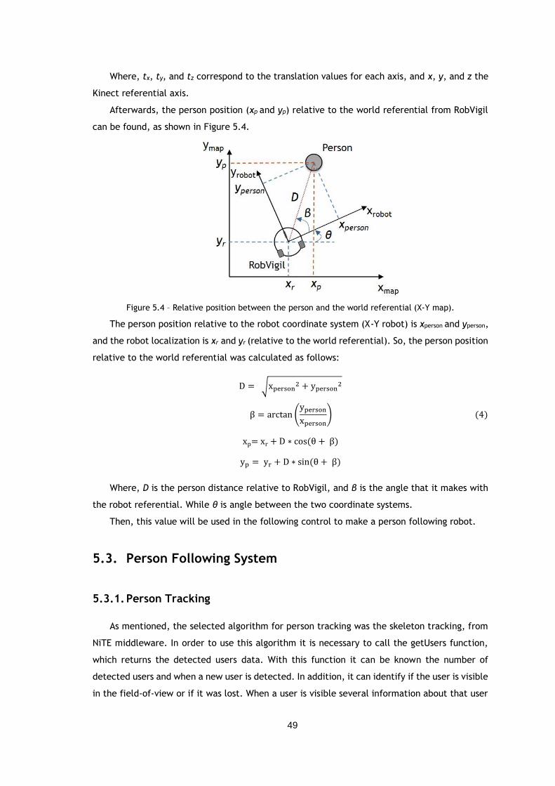
49
Where, tx, ty, and tz correspond to the translation values for each axis, and x, y, and z the
Kinect referential axis.
Afterwards, the person position (xp and yp) relative to the world referential from RobVigil
can be found, as shown in Figure 5.4.
Figure 5.4 – Relative position between the person and the world referential (X-Y map).
The person position relative to the robot coordinate system (X-Y robot) is xperson and yperson,
and the robot localization is xr and yr (relative to the world referential). So, the person position
relative to the world referential was calculated as follows:
D = √xperson2 + yperson
2
β = arctan (yperson
xperson)
xp= xr + D ∗ cos(θ + β)
yp = yr + D ∗ sin(θ + β)
Where, D is the person distance relative to RobVigil, and β is the angle that it makes with
the robot referential. While θ is angle between the two coordinate systems.
Then, this value will be used in the following control to make a person following robot.
5.3. Person Following System
5.3.1. Person Tracking
As mentioned, the selected algorithm for person tracking was the skeleton tracking, from
NiTE middleware. In order to use this algorithm it is necessary to call the getUsers function,
which returns the detected users data. With this function it can be known the number of
detected users and when a new user is detected. In addition, it can identify if the user is visible
in the field-of-view or if it was lost. When a user is visible several information about that user
(4)
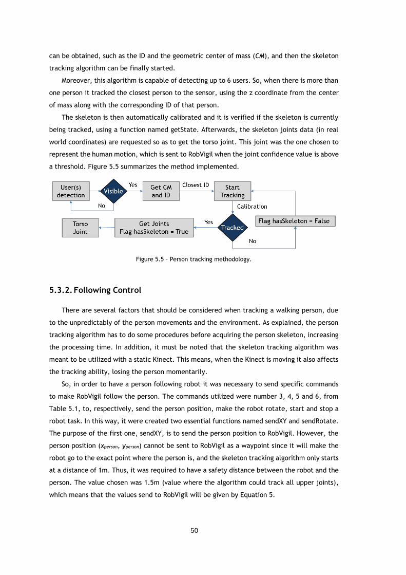
50
can be obtained, such as the ID and the geometric center of mass (CM), and then the skeleton
tracking algorithm can be finally started.
Moreover, this algorithm is capable of detecting up to 6 users. So, when there is more than
one person it tracked the closest person to the sensor, using the z coordinate from the center
of mass along with the corresponding ID of that person.
The skeleton is then automatically calibrated and it is verified if the skeleton is currently
being tracked, using a function named getState. Afterwards, the skeleton joints data (in real
world coordinates) are requested so as to get the torso joint. This joint was the one chosen to
represent the human motion, which is sent to RobVigil when the joint confidence value is above
a threshold. Figure 5.5 summarizes the method implemented.
Figure 5.5 – Person tracking methodology.
5.3.2. Following Control
There are several factors that should be considered when tracking a walking person, due
to the unpredictably of the person movements and the environment. As explained, the person
tracking algorithm has to do some procedures before acquiring the person skeleton, increasing
the processing time. In addition, it must be noted that the skeleton tracking algorithm was
meant to be utilized with a static Kinect. This means, when the Kinect is moving it also affects
the tracking ability, losing the person momentarily.
So, in order to have a person following robot it was necessary to send specific commands
to make RobVigil follow the person. The commands utilized were number 3, 4, 5 and 6, from
Table 5.1, to, respectively, send the person position, make the robot rotate, start and stop a
robot task. In this way, it were created two essential functions named sendXY and sendRotate.
The purpose of the first one, sendXY, is to send the person position to RobVigil. However, the
person position (xperson, yperson) cannot be sent to RobVigil as a waypoint since it will make the
robot go to the exact point where the person is, and the skeleton tracking algorithm only starts
at a distance of 1m. Thus, it was required to have a safety distance between the robot and the
person. The value chosen was 1.5m (value where the algorithm could track all upper joints),
which means that the values send to RobVigil will be given by Equation 5.
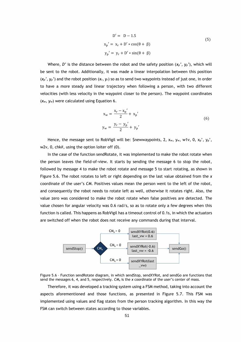
51
D′ = D − 1.5
xp′ = xr + D′ ∗ cos(θ + β)
yp′ = yr + D′ ∗ sin(θ + β)
Where, D’ is the distance between the robot and the safety position (xp’, yp’), which will
be sent to the robot. Additionally, it was made a linear interpolation between this position
(xp’, yp’) and the robot position (xr, yr) so as to send two waypoints instead of just one, in order
to have a more steady and linear trajectory when following a person, with two different
velocities (with less velocity in the waypoint closer to the person). The waypoint coordinates
(xw, yw) were calculated using Equation 6.
xw = xr − xp′
2+ xp′
yw = yr − yp′
2+ yp′
Hence, the message sent to RobVigil will be: $newwaypoints, 2, xw, yw, w1v, 0, xp’, yp’,
w2v, 0, chk#, using the option loiter off (0).
In the case of the function sendRotate, it was implemented to make the robot rotate when
the person leaves the field-of-view. It starts by sending the message 6 to stop the robot,
followed by message 4 to make the robot rotate and message 5 to start rotating, as shown in
Figure 5.6. The robot rotates to left or right depending on the last value obtained from the x
coordinate of the user’s CM. Positives values mean the person went to the left of the robot,
and consequently the robot needs to rotate left as well, otherwise it rotates right. Also, the
value zero was considered to make the robot rotate when false positives are detected. The
value chosen for angular velocity was 0.6 rad/s, so as to rotate only a few degrees when this
function is called. This happens as RobVigil has a timeout control of 0.1s, in which the actuators
are switched off when the robot does not receive any commands during that interval.
Figure 5.6 – Function sendRotate diagram, in which sendStop, sendXYRot, and sendGo are functions that send the messages 6, 4, and 5, respectively. CMx is the x coordinate of the user’s center of mass.
Therefore, it was developed a tracking system using a FSM method, taking into account the
aspects aforementioned and those functions, as presented in Figure 5.7. This FSM was
implemented using values and flag states from the person tracking algorithm. In this way the
FSM can switch between states according to those variables.
(5)
(6)
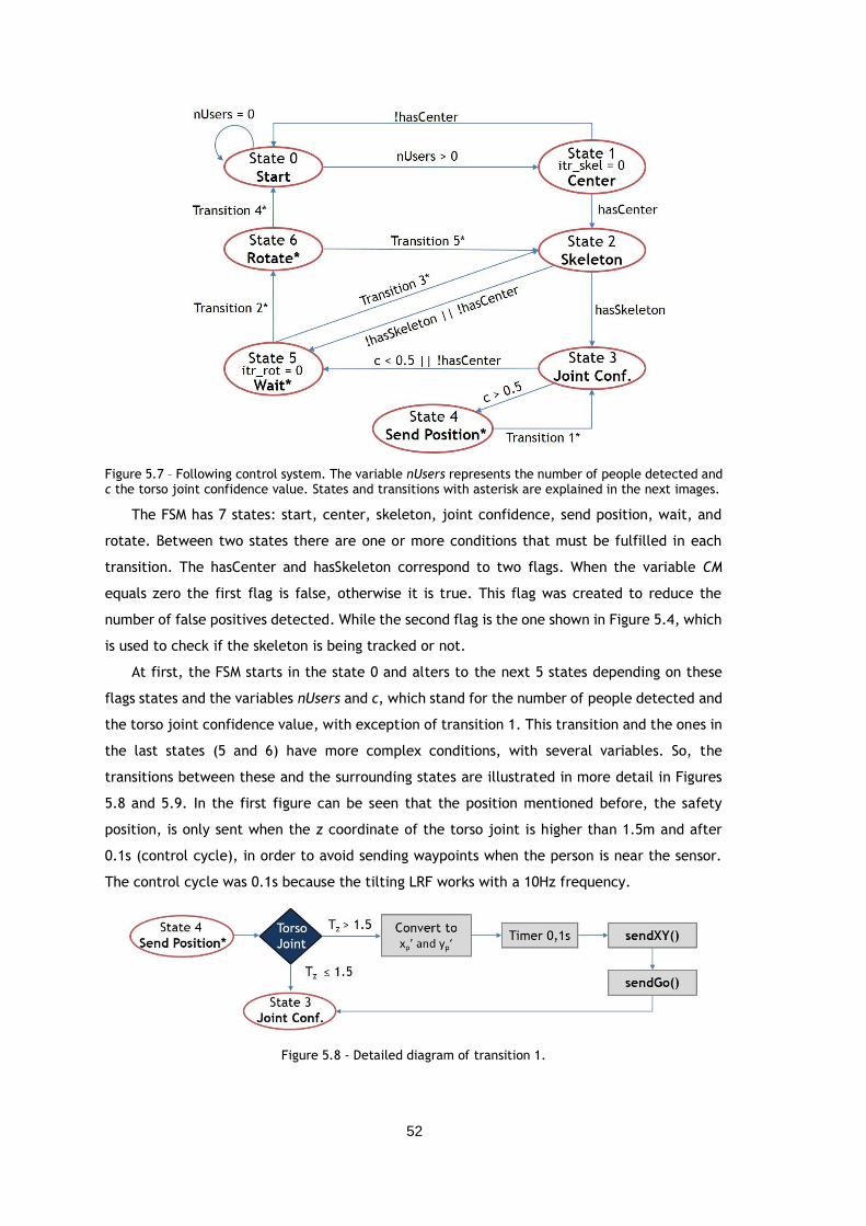
52
Figure 5.7 – Following control system. The variable nUsers represents the number of people detected and c the torso joint confidence value. States and transitions with asterisk are explained in the next images.
The FSM has 7 states: start, center, skeleton, joint confidence, send position, wait, and
rotate. Between two states there are one or more conditions that must be fulfilled in each
transition. The hasCenter and hasSkeleton correspond to two flags. When the variable CM
equals zero the first flag is false, otherwise it is true. This flag was created to reduce the
number of false positives detected. While the second flag is the one shown in Figure 5.4, which
is used to check if the skeleton is being tracked or not.
At first, the FSM starts in the state 0 and alters to the next 5 states depending on these
flags states and the variables nUsers and c, which stand for the number of people detected and
the torso joint confidence value, with exception of transition 1. This transition and the ones in
the last states (5 and 6) have more complex conditions, with several variables. So, the
transitions between these and the surrounding states are illustrated in more detail in Figures
5.8 and 5.9. In the first figure can be seen that the position mentioned before, the safety
position, is only sent when the z coordinate of the torso joint is higher than 1.5m and after
0.1s (control cycle), in order to avoid sending waypoints when the person is near the sensor.
The control cycle was 0.1s because the tilting LRF works with a 10Hz frequency.
Figure 5.8 - Detailed diagram of transition 1.
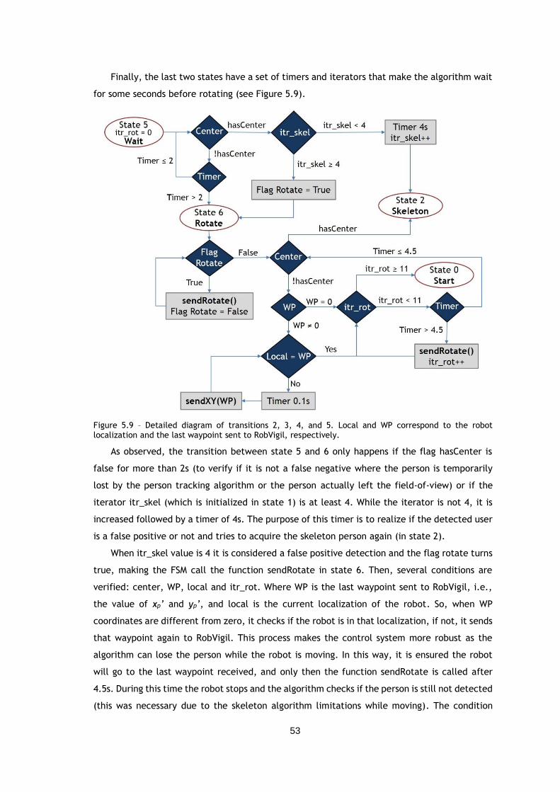
53
Finally, the last two states have a set of timers and iterators that make the algorithm wait
for some seconds before rotating (see Figure 5.9).
Figure 5.9 – Detailed diagram of transitions 2, 3, 4, and 5. Local and WP correspond to the robot localization and the last waypoint sent to RobVigil, respectively.
As observed, the transition between state 5 and 6 only happens if the flag hasCenter is
false for more than 2s (to verify if it is not a false negative where the person is temporarily
lost by the person tracking algorithm or the person actually left the field-of-view) or if the
iterator itr_skel (which is initialized in state 1) is at least 4. While the iterator is not 4, it is
increased followed by a timer of 4s. The purpose of this timer is to realize if the detected user
is a false positive or not and tries to acquire the skeleton person again (in state 2).
When itr_skel value is 4 it is considered a false positive detection and the flag rotate turns
true, making the FSM call the function sendRotate in state 6. Then, several conditions are
verified: center, WP, local and itr_rot. Where WP is the last waypoint sent to RobVigil, i.e.,
the value of xp’ and yp’, and local is the current localization of the robot. So, when WP
coordinates are different from zero, it checks if the robot is in that localization, if not, it sends
that waypoint again to RobVigil. This process makes the control system more robust as the
algorithm can lose the person while the robot is moving. In this way, it is ensured the robot
will go to the last waypoint received, and only then the function sendRotate is called after
4.5s. During this time the robot stops and the algorithm checks if the person is still not detected
(this was necessary due to the skeleton algorithm limitations while moving). The condition
54
‘WP=0’ was also applied in case the robot has not yet received any waypoint. In addition, the
iterator itr_rot was necessary to define a limit of times the function sendRotation could be
used. After sending sendRotation eleven times RobVigil will have completed a full rotation,
which means the person tracking algorithm had lost the person and so the FSM changes to state
0 to start over all the procedure, where the person has to appear in scene to be followed.
5.4. Human-Robot Interaction Control
The human-robot interaction module was developed according to the different gestures
and poses explained before, specifically, the recognition of the three gestures (wave, “stop”,
and “alarm”) and the fall detection system.
As it was mentioned above, the robot will be at a distance of 1.5m from the person. At this
distance the sensor can see all the upper skeleton joints and also some of the bottom joints or
all depending on the user’s height, allowing the person to interact with the robot through the
skeleton tracking.
Consequently, a new flag named Go was added to the FSM, in which the FSM can only call
the function sendGo when this flag is true. This means RobVigil won’t start a task (follow person
or rotate) until this flag turns true. This flag is initialized as true so that the robot follows a
person when someone appears in the field-of-view. Then, the user can order the robot to stop
following him by making the gesture “stop”, or to start following him again with the gesture
wave.
In addition, when an emergency situation is detected (“alarm” gesture or fall), the
algorithm sends two messages to RobVigil, one to make it stop and another to play a sound, in
this case an alarm. To sum up, Table 5.2 shows the messages sent to the robot and the flag Go
state, after a posture is recognized.
Table 5.2 – Messages sent to RobVigil according to the posture recognized and flag Go state.
Gesture/Pose Message Flag Go
Wave - True
“Stop” $STOP, chk# False
“Alarm” $STOP, chk# BP
False
Fall $STOP, chk# BP
False
It must be noted that it was not necessary to calibrate the Kinect sensor, as the image
processing module only used the depth image. In addition, the framework presented does not
require an accurate position of the person, as the torso joint position error when compared to
the physical person body is very small, so the robot still follows the person correctly. On the
other hand, the gestures and fall recognition use several joints, but the algorithms developed
always use relative distances or angles between joints.
55
Chapter 6
Results and Discussion
This chapter presents the tests and the results for the person following scheme and the
human-robot interaction module applied on the platform RobVigil. The performance of the
proposed methodology for HRI is also assessed using the database previously presented. At last,
the results of the image compression and streaming system are analyzed as well.
6.1. Introduction
A set of tests were carried out in order to evaluate the performance of the proposed
system. The embedded processing unit in RobVigil is an Intel® Atom™ CPU D525 @ 1.80GHz
with 1.9GB RAM, and the laptop used to control RobVigil was the same introduced in section
4.1.4. All the experiments were conducted in INESC TEC laboratory, using a local area network
(LAN). The map was previously acquired (with SLAM technique), as well as the 3-D occupancy
grid and the distance matrix.
As mentioned, the person’s position acquired with the Kinect sensor must be converted to
the robot referential. So, the Kinect position relative to the robot referential origin was
measured with a tape-measure in centimeters. The translation values registered for each axis
(tx, ty, and tz) were, respectively, 40.5 ± 0.5 cm, 0 ± 0.5 cm, and 112.0 ± 0.5 cm.
Both images (color and depth) were captured with a resolution of 640x480 at a rate of
30fps. In addition, the Kinect’s elevation angle can be controlled. Thus, the angle chosen for
this framework was -3° so that the floor was visible for the fall detection algorithm.
The results were divided into two parts, database results and RobVigil results. In the last
several approaches were tested for person following and HRI, in which the person moved
forwards and in a circular trajectory, testing also the algorithm ability for cases where the
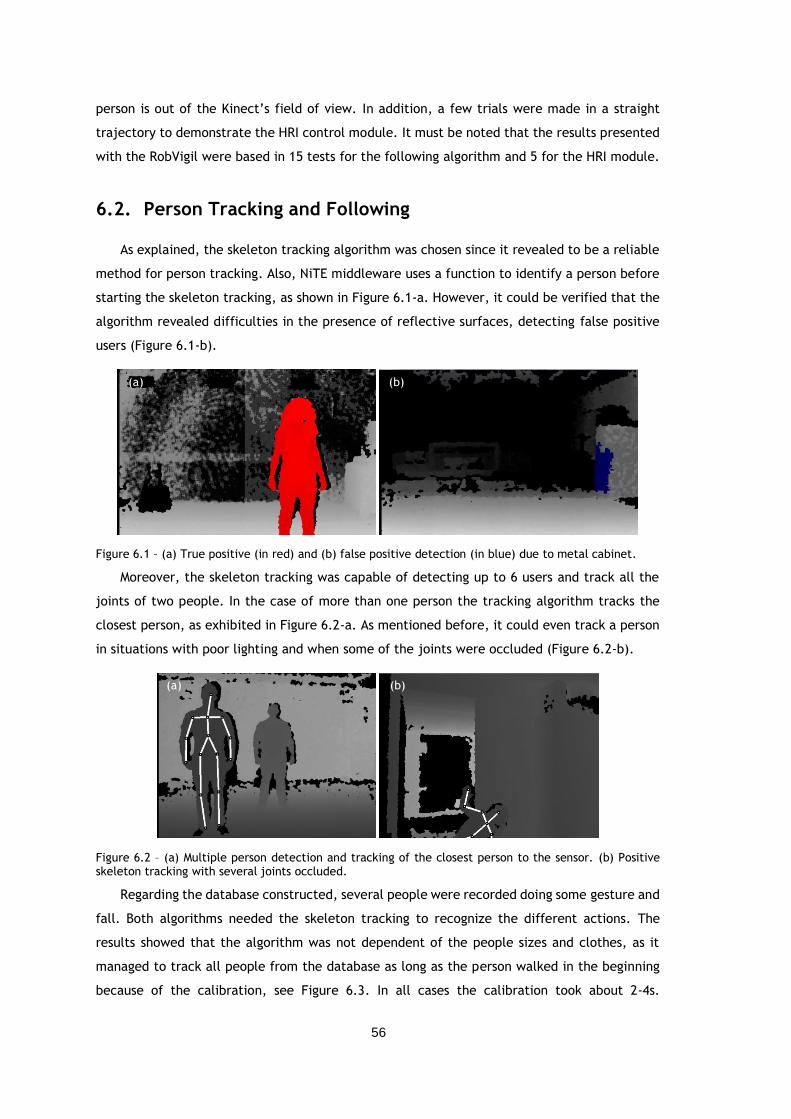
56
person is out of the Kinect’s field of view. In addition, a few trials were made in a straight
trajectory to demonstrate the HRI control module. It must be noted that the results presented
with the RobVigil were based in 15 tests for the following algorithm and 5 for the HRI module.
6.2. Person Tracking and Following
As explained, the skeleton tracking algorithm was chosen since it revealed to be a reliable
method for person tracking. Also, NiTE middleware uses a function to identify a person before
starting the skeleton tracking, as shown in Figure 6.1-a. However, it could be verified that the
algorithm revealed difficulties in the presence of reflective surfaces, detecting false positive
users (Figure 6.1-b).
Figure 6.1 – (a) True positive (in red) and (b) false positive detection (in blue) due to metal cabinet.
Moreover, the skeleton tracking was capable of detecting up to 6 users and track all the
joints of two people. In the case of more than one person the tracking algorithm tracks the
closest person, as exhibited in Figure 6.2-a. As mentioned before, it could even track a person
in situations with poor lighting and when some of the joints were occluded (Figure 6.2-b).
Figure 6.2 – (a) Multiple person detection and tracking of the closest person to the sensor. (b) Positive skeleton tracking with several joints occluded.
Regarding the database constructed, several people were recorded doing some gesture and
fall. Both algorithms needed the skeleton tracking to recognize the different actions. The
results showed that the algorithm was not dependent of the people sizes and clothes, as it
managed to track all people from the database as long as the person walked in the beginning
because of the calibration, see Figure 6.3. In all cases the calibration took about 2-4s.
(b)
(b)
(a)
(a)
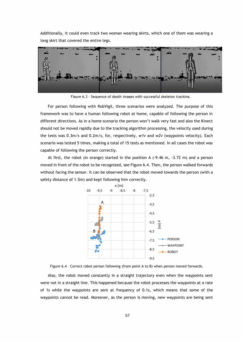
57
Additionally, it could even track two woman wearing skirts, which one of them was wearing a
long skirt that covered the entire legs.
For person following with RobVigil, three scenarios were analyzed. The purpose of this
framework was to have a human following robot at home, capable of following the person in
different directions. As in a home scenario the person won’t walk very fast and also the Kinect
should not be moved rapidly due to the tracking algorithm processing, the velocity used during
the tests was 0.3m/s and 0.2m/s, for, respectively, w1v and w2v (waypoints velocity). Each
scenario was tested 5 times, making a total of 15 tests as mentioned. In all cases the robot was
capable of following the person correctly.
At first, the robot (in orange) started in the position A (-9.46 m, -3.72 m) and a person
moved in front of the robot to be recognized, see Figure 6.4. Then, the person walked forwards
without facing the sensor. It can be observed that the robot moved towards the person (with a
safety distance of 1.5m) and kept following him correctly.
Figure 6.4 – Correct robot person following (from point A to B) when person moved forwards.
Also, the robot moved constantly in a straight trajectory even when the waypoints sent
were not in a straight line. This happened because the robot processes the waypoints at a rate
of 1s while the waypoints are sent at frequency of 0.1s, which means that some of the
waypoints cannot be read. Moreover, as the person is moving, new waypoints are being sent
A
B
-9,5
-8,5
-7,5
-6,5
-5,5
-4,5
-3,5
-2,5
-10 -9,5 -9 -8,5 -8 -7,5
y(m
)
x (m)
PERSON
WAYPOINT
ROBOT
Figure 6.3 – Sequence of depth images with successful skeleton tracking.
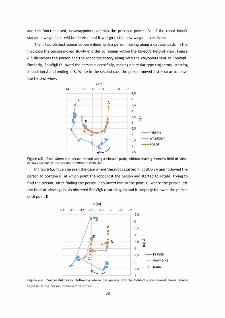
58
and the function used, newwaypoints, deletes the previous points. So, if the robot hasn’t
started a waypoint it will be deleted and it will go to the new waypoint received.
Then, two distinct scenarios were done with a person moving along a circular path. In the
first case the person moved slowly in order to remain within the Kinect’s field-of-view. Figure
6.5 illustrates the person and the robot trajectory along with the waypoints sent to RobVigil.
Similarly, RobVigil followed the person successfully, making a circular type trajectory, starting
in position A and ending in B. While in the second case the person moved faster so as to leave
the field-of-view.
Figure 6.5 – Case where the person moved along a circular path, without leaving Kinect’s field-of-view. Arrow represents the person movement direction.
In Figure 6.6 it can be seen the case where the robot started in position A and followed the
person to position B, at which point the robot lost the person and started to rotate, trying to
find the person. After finding the person it followed him to the point C, where the person left
the field-of-view again. As observed RobVigil rotated again and it properly followed the person
until point D.
Figure 6.6 – Successful person following where the person left the field-of-view several times. Arrow
represents the person movement direction.
A
B
-7,5
-7
-6,5
-6
-5,5
-5
-4,5
-4
-3,5
-3
-2,5
-14 -13 -12 -11 -10 -9 -8 -7
y(m
)x (m)
PERSON
WAYPOINT
ROBOT
A
B
C
D
-7
-6,5
-6
-5,5
-5
-4,5
-4
-3,5
-3
-2,5
-14 -13 -12 -11 -10 -9 -8 -7
y(m
)
x (m)
PERSON
WAYPOINT
ROBOT
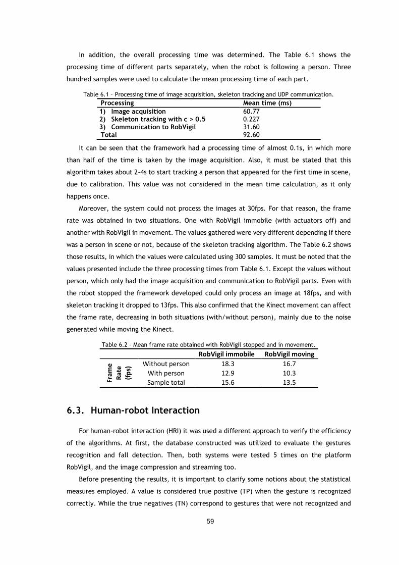
59
In addition, the overall processing time was determined. The Table 6.1 shows the
processing time of different parts separately, when the robot is following a person. Three
hundred samples were used to calculate the mean processing time of each part.
Table 6.1 – Processing time of image acquisition, skeleton tracking and UDP communication.
Processing Mean time (ms)
1) Image acquisition 60.77 2) Skeleton tracking with c > 0.5 0.227 3) Communication to RobVigil 31.60 Total 92.60
It can be seen that the framework had a processing time of almost 0.1s, in which more
than half of the time is taken by the image acquisition. Also, it must be stated that this
algorithm takes about 2-4s to start tracking a person that appeared for the first time in scene,
due to calibration. This value was not considered in the mean time calculation, as it only
happens once.
Moreover, the system could not process the images at 30fps. For that reason, the frame
rate was obtained in two situations. One with RobVigil immobile (with actuators off) and
another with RobVigil in movement. The values gathered were very different depending if there
was a person in scene or not, because of the skeleton tracking algorithm. The Table 6.2 shows
those results, in which the values were calculated using 300 samples. It must be noted that the
values presented include the three processing times from Table 6.1. Except the values without
person, which only had the image acquisition and communication to RobVigil parts. Even with
the robot stopped the framework developed could only process an image at 18fps, and with
skeleton tracking it dropped to 13fps. This also confirmed that the Kinect movement can affect
the frame rate, decreasing in both situations (with/without person), mainly due to the noise
generated while moving the Kinect.
Table 6.2 – Mean frame rate obtained with RobVigil stopped and in movement.
RobVigil immobile RobVigil moving
Fram
e
Rat
e
(fp
s) Without person 18.3 16.7
With person 12.9 10.3
Sample total 15.6 13.5
6.3. Human-robot Interaction
For human-robot interaction (HRI) it was used a different approach to verify the efficiency
of the algorithms. At first, the database constructed was utilized to evaluate the gestures
recognition and fall detection. Then, both systems were tested 5 times on the platform
RobVigil, and the image compression and streaming too.
Before presenting the results, it is important to clarify some notions about the statistical
measures employed. A value is considered true positive (TP) when the gesture is recognized
correctly. While the true negatives (TN) correspond to gestures that were not recognized and
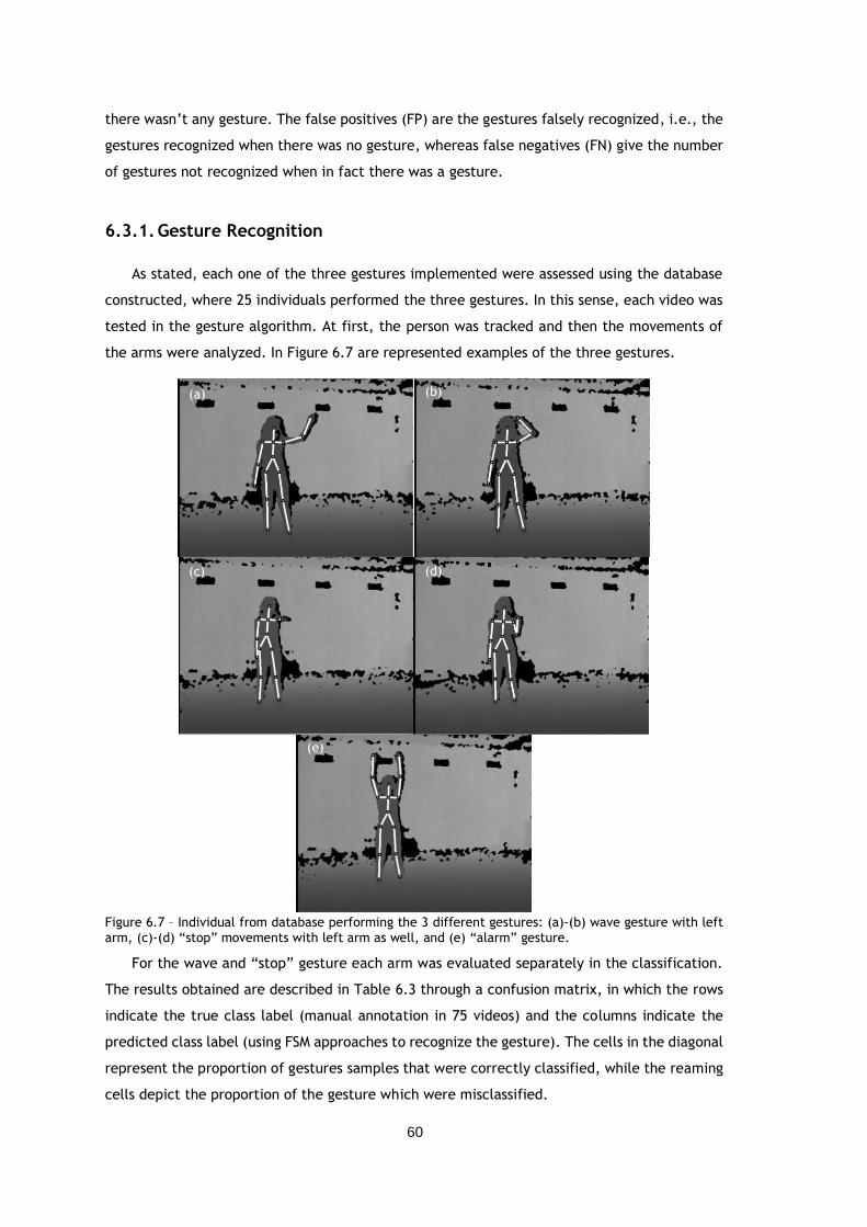
60
there wasn’t any gesture. The false positives (FP) are the gestures falsely recognized, i.e., the
gestures recognized when there was no gesture, whereas false negatives (FN) give the number
of gestures not recognized when in fact there was a gesture.
6.3.1. Gesture Recognition
As stated, each one of the three gestures implemented were assessed using the database
constructed, where 25 individuals performed the three gestures. In this sense, each video was
tested in the gesture algorithm. At first, the person was tracked and then the movements of
the arms were analyzed. In Figure 6.7 are represented examples of the three gestures.
Figure 6.7 – Individual from database performing the 3 different gestures: (a)-(b) wave gesture with left
arm, (c)-(d) “stop” movements with left arm as well, and (e) “alarm” gesture.
For the wave and “stop” gesture each arm was evaluated separately in the classification.
The results obtained are described in Table 6.3 through a confusion matrix, in which the rows
indicate the true class label (manual annotation in 75 videos) and the columns indicate the
predicted class label (using FSM approaches to recognize the gesture). The cells in the diagonal
represent the proportion of gestures samples that were correctly classified, while the reaming
cells depict the proportion of the gesture which were misclassified.
(a) (b)
(c) (d)
(e)
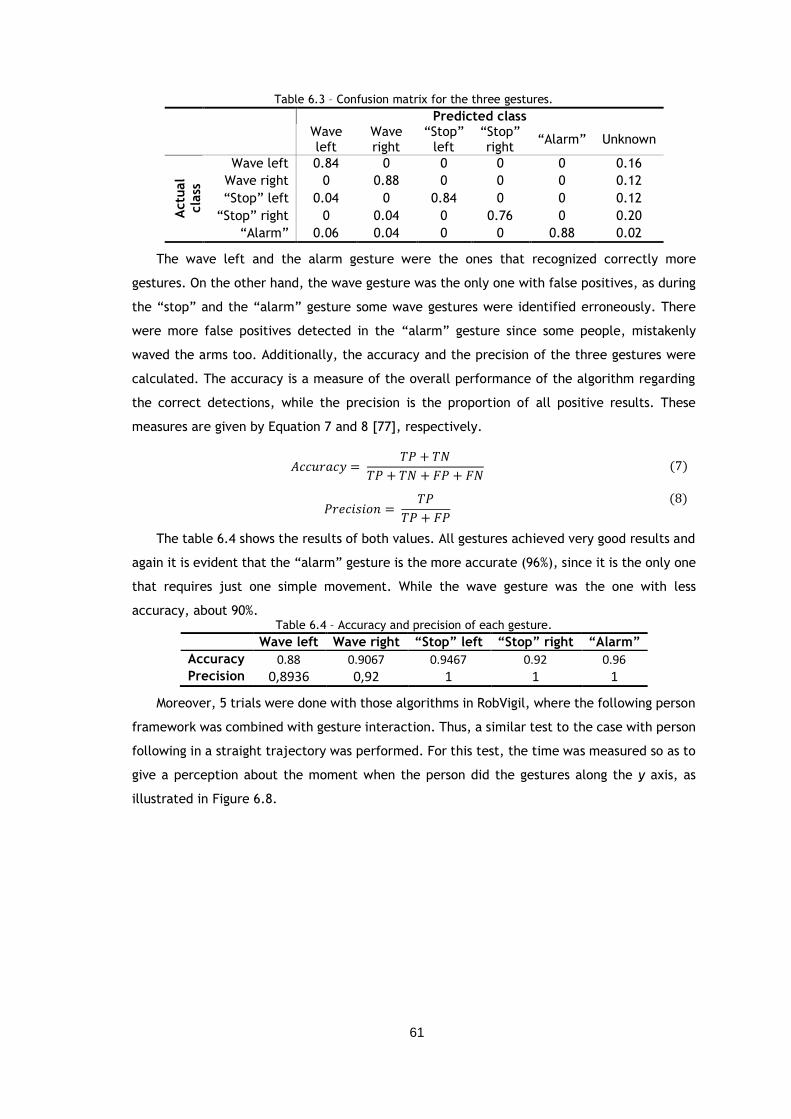
61
Table 6.3 – Confusion matrix for the three gestures.
Predicted class Wave
left Wave right
“Stop” left
“Stop” right
“Alarm” Unknown
Actu
al
cla
ss
Wave left 0.84 0 0 0 0 0.16
Wave right 0 0.88 0 0 0 0.12
“Stop” left 0.04 0 0.84 0 0 0.12
“Stop” right 0 0.04 0 0.76 0 0.20
“Alarm” 0.06 0.04 0 0 0.88 0.02
The wave left and the alarm gesture were the ones that recognized correctly more
gestures. On the other hand, the wave gesture was the only one with false positives, as during
the “stop” and the “alarm” gesture some wave gestures were identified erroneously. There
were more false positives detected in the “alarm” gesture since some people, mistakenly
waved the arms too. Additionally, the accuracy and the precision of the three gestures were
calculated. The accuracy is a measure of the overall performance of the algorithm regarding
the correct detections, while the precision is the proportion of all positive results. These
measures are given by Equation 7 and 8 [77], respectively.
𝐴𝑐𝑐𝑢𝑟𝑎𝑐𝑦 = 𝑇𝑃 + 𝑇𝑁
𝑇𝑃 + 𝑇𝑁 + 𝐹𝑃 + 𝐹𝑁
𝑃𝑟𝑒𝑐𝑖𝑠𝑖𝑜𝑛 = 𝑇𝑃
𝑇𝑃 + 𝐹𝑃
The table 6.4 shows the results of both values. All gestures achieved very good results and
again it is evident that the “alarm” gesture is the more accurate (96%), since it is the only one
that requires just one simple movement. While the wave gesture was the one with less
accuracy, about 90%. Table 6.4 – Accuracy and precision of each gesture.
Wave left Wave right “Stop” left “Stop” right “Alarm”
Accuracy 0.88 0.9067 0.9467 0.92 0.96 Precision 0,8936 0,92 1 1 1
Moreover, 5 trials were done with those algorithms in RobVigil, where the following person
framework was combined with gesture interaction. Thus, a similar test to the case with person
following in a straight trajectory was performed. For this test, the time was measured so as to
give a perception about the moment when the person did the gestures along the y axis, as
illustrated in Figure 6.8.
(7)
(8)
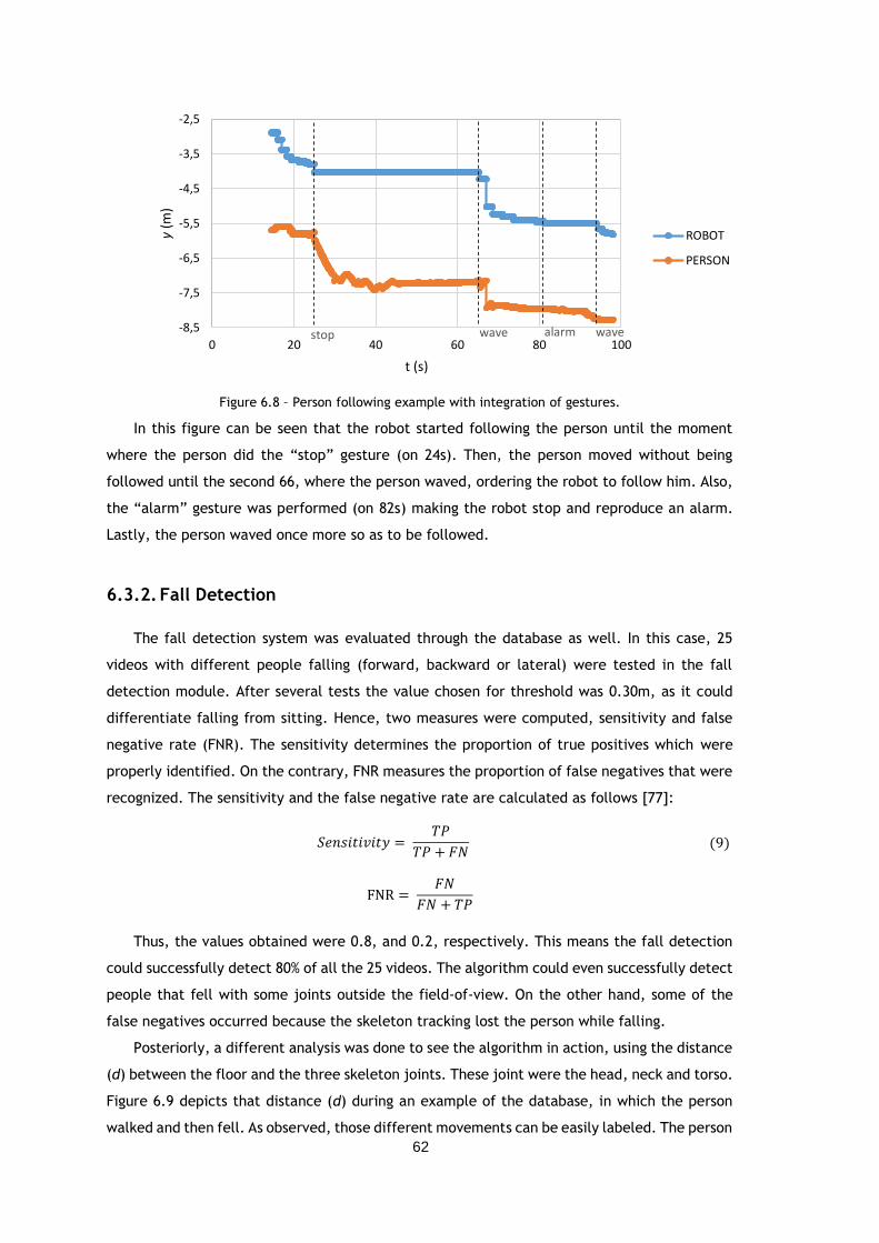
62
Figure 6.8 – Person following example with integration of gestures.
In this figure can be seen that the robot started following the person until the moment
where the person did the “stop” gesture (on 24s). Then, the person moved without being
followed until the second 66, where the person waved, ordering the robot to follow him. Also,
the “alarm” gesture was performed (on 82s) making the robot stop and reproduce an alarm.
Lastly, the person waved once more so as to be followed.
6.3.2. Fall Detection
The fall detection system was evaluated through the database as well. In this case, 25
videos with different people falling (forward, backward or lateral) were tested in the fall
detection module. After several tests the value chosen for threshold was 0.30m, as it could
differentiate falling from sitting. Hence, two measures were computed, sensitivity and false
negative rate (FNR). The sensitivity determines the proportion of true positives which were
properly identified. On the contrary, FNR measures the proportion of false negatives that were
recognized. The sensitivity and the false negative rate are calculated as follows [77]:
𝑆𝑒𝑛𝑠𝑖𝑡𝑖𝑣𝑖𝑡𝑦 = 𝑇𝑃
𝑇𝑃 + 𝐹𝑁
FNR = 𝐹𝑁
𝐹𝑁 + 𝑇𝑃
Thus, the values obtained were 0.8, and 0.2, respectively. This means the fall detection
could successfully detect 80% of all the 25 videos. The algorithm could even successfully detect
people that fell with some joints outside the field-of-view. On the other hand, some of the
false negatives occurred because the skeleton tracking lost the person while falling.
Posteriorly, a different analysis was done to see the algorithm in action, using the distance
(d) between the floor and the three skeleton joints. These joint were the head, neck and torso.
Figure 6.9 depicts that distance (d) during an example of the database, in which the person
walked and then fell. As observed, those different movements can be easily labeled. The person
stop wave alarm wave-8,5
-7,5
-6,5
-5,5
-4,5
-3,5
-2,5
0 20 40 60 80 100
y(m
)
t (s)
ROBOT
PERSON
(9)
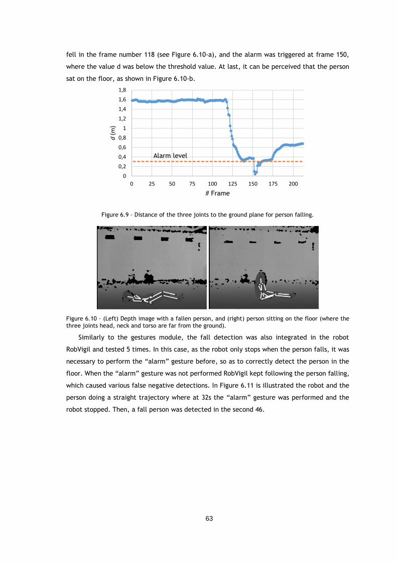
63
fell in the frame number 118 (see Figure 6.10-a), and the alarm was triggered at frame 150,
where the value d was below the threshold value. At last, it can be perceived that the person
sat on the floor, as shown in Figure 6.10-b.
Figure 6.9 – Distance of the three joints to the ground plane for person falling.
Figure 6.10 – (Left) Depth image with a fallen person, and (right) person sitting on the floor (where the
three joints head, neck and torso are far from the ground).
Similarly to the gestures module, the fall detection was also integrated in the robot
RobVigil and tested 5 times. In this case, as the robot only stops when the person falls, it was
necessary to perform the “alarm” gesture before, so as to correctly detect the person in the
floor. When the “alarm” gesture was not performed RobVigil kept following the person falling,
which caused various false negative detections. In Figure 6.11 is illustrated the robot and the
person doing a straight trajectory where at 32s the “alarm” gesture was performed and the
robot stopped. Then, a fall person was detected in the second 46.
0
0,2
0,4
0,6
0,8
1
1,2
1,4
1,6
1,8
0 25 50 75 100 125 150 175 200
d(m
)
# Frame
Alarm level
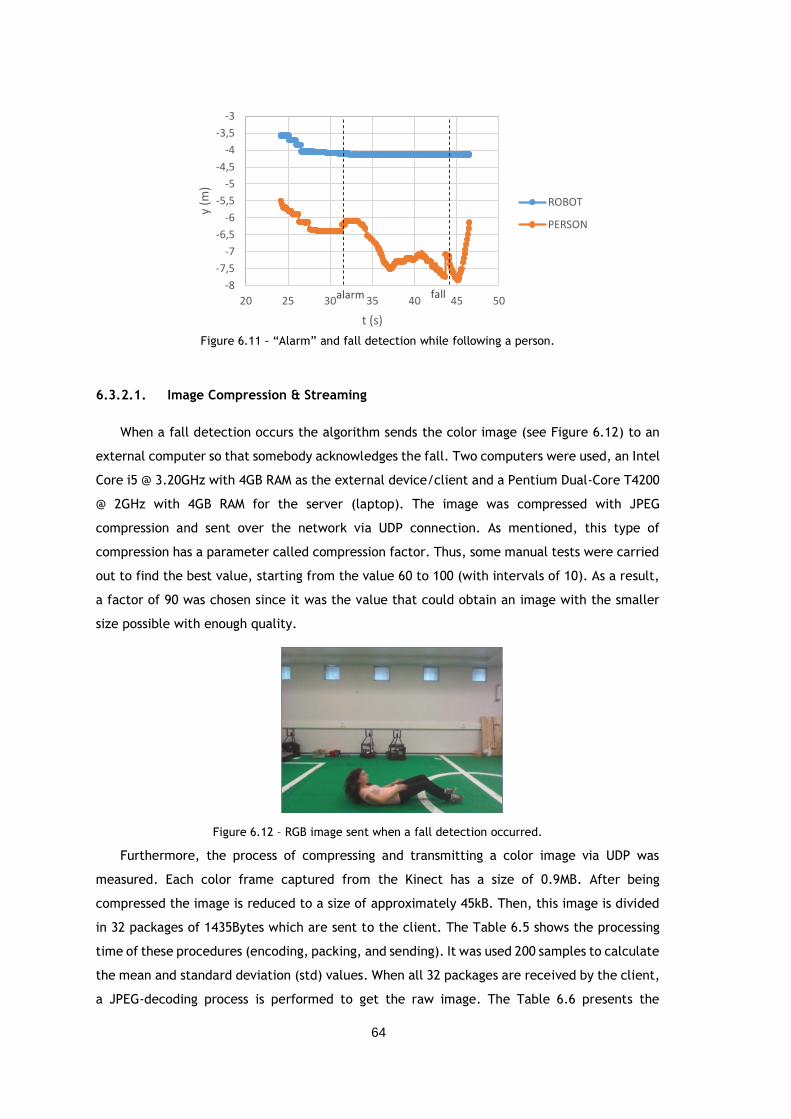
64
Figure 6.11 – “Alarm” and fall detection while following a person.
6.3.2.1. Image Compression & Streaming
When a fall detection occurs the algorithm sends the color image (see Figure 6.12) to an
external computer so that somebody acknowledges the fall. Two computers were used, an Intel
Core i5 @ 3.20GHz with 4GB RAM as the external device/client and a Pentium Dual-Core T4200
@ 2GHz with 4GB RAM for the server (laptop). The image was compressed with JPEG
compression and sent over the network via UDP connection. As mentioned, this type of
compression has a parameter called compression factor. Thus, some manual tests were carried
out to find the best value, starting from the value 60 to 100 (with intervals of 10). As a result,
a factor of 90 was chosen since it was the value that could obtain an image with the smaller
size possible with enough quality.
Figure 6.12 – RGB image sent when a fall detection occurred.
Furthermore, the process of compressing and transmitting a color image via UDP was
measured. Each color frame captured from the Kinect has a size of 0.9MB. After being
compressed the image is reduced to a size of approximately 45kB. Then, this image is divided
in 32 packages of 1435Bytes which are sent to the client. The Table 6.5 shows the processing
time of these procedures (encoding, packing, and sending). It was used 200 samples to calculate
the mean and standard deviation (std) values. When all 32 packages are received by the client,
a JPEG-decoding process is performed to get the raw image. The Table 6.6 presents the
alarm fall-8
-7,5
-7
-6,5
-6
-5,5
-5
-4,5
-4
-3,5
-3
20 25 30 35 40 45 50
y (m
)
t (s)
ROBOT
PERSON
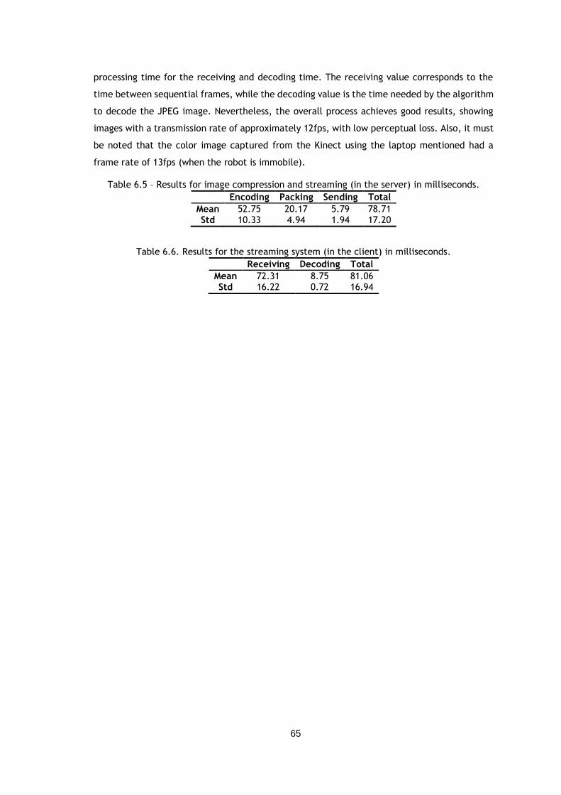
65
processing time for the receiving and decoding time. The receiving value corresponds to the
time between sequential frames, while the decoding value is the time needed by the algorithm
to decode the JPEG image. Nevertheless, the overall process achieves good results, showing
images with a transmission rate of approximately 12fps, with low perceptual loss. Also, it must
be noted that the color image captured from the Kinect using the laptop mentioned had a
frame rate of 13fps (when the robot is immobile).
Table 6.5 – Results for image compression and streaming (in the server) in milliseconds.
Encoding Packing Sending Total
Mean 52.75 20.17 5.79 78.71 Std 10.33 4.94 1.94 17.20
Table 6.6. Results for the streaming system (in the client) in milliseconds.
Receiving Decoding Total
Mean 72.31 8.75 81.06 Std 16.22 0.72 16.94
66
Chapter 7
Conclusions and Future Work
The main focus of this dissertation was centered on the integration of a device relatively
new, the Kinect, to a robotic platform in order to adapt it with AAL capabilities. Thus, several
methods for person following and human-robot interaction (HRI) were studied and implemented
using the platform RobVigil. This allowed a detailed understanding about distinct algorithms
for face detection and tracking, body detection and tracking, gesture recognition, fall
detection, and image compression and streaming.
In terms of face algorithms, it can be concluded that the Kinect SDK’s face tracking could
reach higher distances and could track a face even under poor light conditions, due to the
depth data. Whereas the OpenCV algorithm was more susceptible to false positives due to
illumination variations, as camshift operates with color distribution, and the face detection
algorithm only worked for small distances. Nevertheless, the main difference was the frame
rate between the two algorithms, in which the first one was able of tracking with a higher
frame rate.
However, face algorithms require the person to be facing the sensor. So, the skeleton
tracking algorithm was also tested which showed to be an important algorithm for person
tracking, since it could estimate the joints in several conditions, even when the sensor could
not see the full skeleton. In addition, two libraries were taken into account, Kinect SDK and
NiTE. The last one was better in two aspects: distance ability and frame rate. Therefore, it
was established a potential method for person following and HRI using the skeleton tracking
from NiTE.
Regarding this framework, the presented results proved that the robot could follow the
person in different cases and trajectories. Even in cases where the person left the field-of-
view, the robot followed the person, using rotation commands. On the other hand, the overall
processing time was about 0.1s, reducing the frame rate to 10 fps when following the person.
67
Also, the database created provided some interesting results, which proved that distances
and angles approaches extracted from the skeleton joints were suitable features for gesture
recognition and fall detection. Despite using a simple method through FSM approaches, all the
gestures had accuracy values greater than 90%, except the gesture wave left, which had some
false positives. However, it must be noted that some of the false positives occurred because
the person performed the gestures incorrectly. Whereas for fall detection the approach
developed could detect correctly 80% of the cases. Although when integrated in the platform
RobVigil a fall is better detected when the robot is stopped before.
Lastly, the compression and streaming scheme from [65] demonstrated notable results
when compressing the color image as it reduced the image size with a ratio of 1:20. In addition,
the streaming scheme revealed good results taken into account the laptop and the network
used.
Future Work
Although the proposed framework presented some noteworthy results, further
enhancements should be considered to improve the algorithm robustness. Namely,
implementation of the framework in a device (PC/laptop) with a better processor so as to fulfill
all the Kinect requirements, on a domestic wireless network.
Regarding vision algorithms, face recognition could be a useful algorithm to help the
skeleton tracking, since the developed algorithm tracked the closest person to the sensor. In
this way, tracking of a specific person could be possible, combining a face with the skeleton
tracking ID.
Also, the integration of a tilting servo with the Kinect on top would decrease battery
resources, as the robot would move less and could contribute to a different approach for person
following, using an adaptive person following algorithm [78] which generates a path taking into
account obstacles.
About the HRI module, the algorithms should be tested in a larger database, in order to
obtain more reliable results. In addition, some future work should be done using evolved
learning algorithms, such as a SVM approach. In this way, the threshold to recognize a gesture
would be more accurate. Moreover, time constraints should be included to avoid recognition
of different gestures in a small time interval, because it is unlikely that the person did two
different gestures successively.
Finally, for fall detection, velocity features computed from the skeleton joints should be
added to reduce fall positives, for example, in situations that the person lays down on the
floor.
68
References
[1] N. Roy, G. Baltus, D. Fox, F. Gemperle, J. Goetz, T. Hirsch, D. Margaritis, M. Montemerlo,
J. Pineau, J. Schulte and S. Thrun, "Towards Personal Service Robots for the Elderly”,
Workshop on Interactive Robots and Entertainment, pp. 1-6, 2000.
[2] "Ambient Assisted Living Joint Programme”, [Online]. Available: http://www.aal-
europe.eu/. [Accessed 21 May 2013].
[3] E. S. Network, “Services for older people in Europe”, 2008.
[4] C. Tonelo, A. P. Moreira and G. Veiga, "Evaluation of sensors and algorithms for person
detection for personal robots”, IEEE 15th International Conference on e-Health
Networking, Applications & Services (Healthcom), pp. 60-65, 2013.
[5] J. Nehmer, A. Karshmer, M. Becker and R. Lamm, "Living Assistance Systems - An Ambient
Intelligence Approach -”, pp. 1-8, 2006.
[6] A. Tapus, M. Mataric and B. Scassellati, "Socially Assistive Robotics”, IEEE Robotics &
Automation Magazine, vol. 14, pp. 35-42, 2007.
[7] J. Pineau, M. Montemerlo, M. Pollack, N. Roy and S. Thrun, "Towards robotic assistants
in nursing homes: Challenges and results”, Robotics and Autonomous Systems, vol. 42,
pp. 271-281, 2003.
[8] B. Graf, P. C. and M. Hägele, "Robotic Home Assistant Care-O-bot 3 Product Vision and
Innovation Platform”, J.A. Jacko (Ed.): Human-Computer Interaction, vol. 2, p. 312–320,
2009.
[9] K. Berns and S. A. Mehdi, "Use of an Autonomous Mobile Robot for Elderly Care”,
Proceedings of the 2010 Advanced Technologies for Enhancing Quality of Life, pp. 121-
126, 2010.
[10] H.-M. Gross, C. Schroeter, S. Mueller, M. Volkhardt, E. Einhorn, A. Bley, T. Langner, C.
Martin and M. Merten, "I’ll keep an Eye on You: Home Robot Companion for Elderly People
with Cognitive Impairment”, IEEE Int. Conf. on Systems, Man, and Cybernetics, pp. 2481-
2488, 2011.
[11] D. Lowet, M. Isken, W. Lee, F. van Heesch and E. Eertink, "Robotic Telepresence for 24/07
remote Assistance to Elderly at Home”, IEEE International Symposium on Robot and
Human Interactive Communication, pp. 1-7, 2012.
69
[12] E. Lucet, "Marketing documents”, [Online]. Available: http://www.doc-
center.robosoft.com/@api/deki/files/5069/%3dRobosoft_KompaiRobot.pdf. [Accessed
22 May 2013].
[13] S. Coradeschi, A. Cesta, G. Cortellessa, L. Coraci, J. Gonzalez, L. Karlsson, F. Furfari, A.
Loutfi, A. Orlandini, F. Palumbo, F. Pecora, S. von Rump, A. Stimec, J. Ullberg and B.
Otslund, "GiraffPlus: Combining social interaction and long term monitoring for promoting
independent living”, The 6th International Conference on Human System Interaction, pp.
578-585, 2013.
[14] A. Beristai, "Industrial Robotics Research Group”, [Online]. Available:
http://robotics.dem.uc.pt/echord/ECHORD_ERF2013_VICOMTECH.pdf. [Accessed 22 May
2013].
[15] C. Wong, D. Kortenkamp and M. Speich, "A mobile robot that recognizes people”, 7th
International Conference on Tools with Artificial Intelligence, pp. 346 - 353, 1995.
[16] S. S. Ghidary, Y. Nakata, T. Takamori and M. Hattori, "Head and Face Detection at Indoor
Environment by Home Robot”, International Workshop on Robot and Human Interactive
Communication, pp. 1-7, 2000.
[17] T. Wilhelm, H.-J. Böhme and H.-M. Gross, "A Multi-Modal System for Tracking and
Analyzing Faces on a Mobile Robot”, Robotics and Autonomous Systems, vol. 48, pp. 31-
40, 2004.
[18] J. Fritsch, M. Kleinehagenbrock, S. Lang, G. A. Fink and G. Sagerer, "Audiovisual Person
Tracking with a Mobile Robot”, Proccedings of International Conference on Intelligent
Autonomous Systems, pp. 898-906, 2004.
[19] N. Bellotto and H. Hu, "Multisensor-based human detection and tracking for mobile
service robots”, IEEE Transactions on Systems, Man, and Cybernetics, Part B:
Cybernetics, vol. 39, pp. 167-181, 2009.
[20] G. Cielniak, T. Ducketta and A. J. Lilienthal, "Data Association and Occlusion Handling for
Vision-Based People Tracking by Mobile Robots”, Robotics and Autonomous Systems, vol.
58, pp. 435-443, 2010.
[21] A. Fernández-Caballeroa, J. C. Castilloa, J. Martínez-Cantos and R. Martínez-Tomás,
"Optical flow or image subtraction in human detection from infrared camera on mobile
robot”, Robotics and Autonomous Systems, vol. 58, p. 1273–1281, 2010.
[22] M. Correa, G. Hermosilla, R. Verschae and J. Ruiz-del-Solar, "Human Detection and
Identification by Robots Using Thermal and Visual Information in Domestic Environments”,
Journal of Intelligent & Robotic Systems, vol. 66, p. 223–243, 2012.
[23] J. A. Méndez-Polanco, A. Muñoz-Meléndez and E. F. Morales, "People Detection by a
Mobile Robot Using Stereo Vision in Dynamic Indoor Environments”, MICAI 2009: Advances
in Artificial Intelligence, pp. 349-359, 2009.
[24] A. Treptow, G. Cielniak and T. Duckett, "Real-time people tracking for mobile robots
using thermal vision”, Robotics and Autonomous Systems, vol. 54, p. 729–739, 2006.
[25] G. Medioni, A. R. J. François, M. Siddiqui, K. Kim and H. Yoon, "Robust real-time vision
for a personal service robot”, Computer Vision and Image Understanding, vol. 108, pp.
196-203, 2007.
[26] J. Satake and J. Miura, "Robust Stereo-based Person Detecting and Tracking for a Person
Following Robot”, Proceedings of the IEEE International Conference on Robotics and
Automation, pp. 1-6, 2009.
[27] S.-K. Song, "OMG Robotics DTF 2012”, [Online]. Available:
http://staff.aist.go.jp/t.kotoku/omg/2012Burlingame/robotics2012-12-04.pdf.
[Accessed 28 May 2013].
70
[28] P. Viola and M. Jones, "Robust Real-Time Face Detection”, International Journal of
Computer Vision, vol. 57, no. 2, pp. 137-154, 2004.
[29] N. Dalal and B. Triggs, "Histograms of Oriented Gradients for Human Detection”,
International Conference on Computer Vision & Pattern Recognition, vol. 1, pp. 886-893,
2005.
[30] A. M. Pinto, A. P. Moreira, M. V. Correia and P. G. Costa, "A Flow-based Motion Perception
Technique for an Autonomous Robot System”, Journal of Intelligent & Robotic Systems,
pp. 1-18, 2013.
[31] W. Choi, P. C. and S. S., "Detecting and Tracking People using an RGB-D Camera via
Multiple Detector Fusion”, IEEE International Conference on Computer Vision Workshops,
pp. 1076-1083, 2012.
[32] E. Machida, M. Cao, T. Murao and H. Hashimoto, "Human Motion Tracking of Mobile Robot
with Kinect 3D Sensor”, Proceedings of SICE Annual Conference (SICE), pp. 2207-2211,
2012.
[33] Microsoft Corporation, "Kinect for Windows”, [Online]. Available:
http://www.microsoft.com/en-us/kinectforwindows/. [Accessed 10 February 2014].
[34] G. Galatas, S. Ferdous and F. Makedon, "Multi-modal Person Localization And Emergency
Detection Using The Kinect”, International Journal of Advanced Research in Artificial
Intelligence, vol. 2, pp. 41-46, 2013.
[35] OpenNI, "OpenNI Organization”, [Online]. Available: http://www.openni.org/. [Accessed
11 January 2014].
[36] PrimeSense, "NiTE”, [Online]. Available: http://www.primesense.com/solutions/nite-
middleware/. [Accessed 11 January 2014].
[37] J. Wu, G. Pan, D. Zhang, G. Qi and S. Li, "Gesture Recognition with a 3-D Accelerometer”,
Proccedings of the 6th Interantional Conference on Ubiquitous Intelligence and
Computing, pp. 25-38, 2009.
[38] S. Waldherr, R. Romero and T. S., "A Gesture Based Interface for Human-Robot
Interaction”, Autonomous Robots, vol. 9, pp. 151-173, 2000.
[39] A. Corradini, "Dynamic Time Warping for Off-line Recognition of a Small Gesture
Vocabulary”, IEEE ICCV Workshop on Recognition, Analysis, and Tracking of Faces and
Gestures in Real-Time Systems, pp. 82-89, 2001.
[40] R. Stiefelhagen, C. Fugen, R. Gieselmann, H. Holzapfel, K. Nickel and A. Waibel, "Natural
Human-Robot Interaction using Speech,Head Pose and Gestures”, IEEE/RSJ International
Conference on Intelligent Robots and Systems, vol. 3, pp. 1-6, 2004.
[41] S.-W. Lee, "Automatic Gesture Recognition for Intelligent Human-Robot Interaction”,
Proceedings of the 7th International Conference on Automatic Face and Gesture
Recognition, pp. 645-650, 2006.
[42] R. Mangera, "Static gesture recognition using features extracted from skeletal data”,
Proceeding of the Pattern Recognition Association of South Africa, pp. 1-5, 2013.
[43] P. Doliotis, A. Stefan, C. McMurrough, E. D. and V. Athitsos, "Comparing Gesture
Recognition Accuracy Using Color and Depth Information”, Proceedings of the 4th
International Conference on Pervasive Technologies Related to Assistive Environments,
pp. 1-7, 2011.
[44] M. Van den Bergh, D. Carton, R. De Nijs, N. Mitsou, C. Landsiedel, K. Kuehnlenz, D.
Wollherr, L. Van Gool and M. Buss, "Real-time 3D Hand Gesture Interaction with a Robot
for Understanding Directions from Humans”, 20th IEEE International Symposium on Robot
and Human Interactive Communication, pp. 357-362, 2011.
71
[45] F. Kistler, B. Endrass, I. Damian, C. T. Dang and E. André, "Natural Interaction with
Culturally Adaptive Virtual Characters”, Journal on Multimodal User Interfaces, vol. 6,
pp. 39-47, 2011.
[46] T. Degen, H. Jaeckel, M. Rufer and S. Wyss, "SPEEDY: A Fall Detector in a Wrist Watch”,
Proccedings of Seventh IEEE International Symposium on Wearable Computers, pp. 184-
187, 2003.
[47] Future-Shape, “SensFloor® – large-area sensor system”, [Online]. Available:
http://www.future-shape.de/en/technologies/23. [Accessed 21 January 2014].
[48] D. Anderson, J. M. Keller, M. Skubic, X. Chen and Z. He, "Recognizing Falls from
Silhouettes”, Proceedings of the 28th IEEE EMBS Annual International Conference, pp.
6388-6391, 2006.
[49] Y.-C. Huang, S.-G. Miaou and T.-Y. Liao, "A Human Fall Detection System Using an Omni-
Directional Camera”, IAPR Conference on Machine Vision Applications, pp. 455-458, 2009.
[50] M. Shoaib, R. Dragon and J. Ostermann, "Context-aware visual analysis of elderly activity
in a cluttered home environment”, EURASIP Journal on Advances in Signal Processing, pp.
1-14, 2011.
[51] C. Zhang, Y. Tian and E. Capezuti, "Privacy Preserving Automatic Fall Detection for Elderly
Using RGBD Cameras”, Computers Helping People with Special Needs, pp. 625-633, 2012.
[52] C. Kawatsu, J. Li and C. J. Chung, "Development of a Fall Detection System with Microsoft
Kineck”, Robot Intelligence Technology and Applications, vol. 208, pp. 623-630, 2013.
[53] M. Kepski and B. Kwolek, "Human Fall Detection Using Kinect Sensor”, Proceedings of the
8th International Conference on Computer Recognition Systems, vol. 226, pp. 743-752,
2013.
[54] M. Volkhardt, F. Schneemann and H.-M. Gross, "Fallen Person Detection for Mobile Robots
using 3D Depth Data”, IEEE International Conference on Systems, Man, and Cybernetics,
pp. 3573-3578, 2013.
[55] J. Liu, M. Wang and B. Feng, "iBotGuard: an Internet-based Intelligent Robot security
system using Invariant Face Recognition against intruder”, IEEE Transactions on Systems,
Man, and Cybernetics, Part C: Applications and Reviews, pp. 97-105, 2005.
[56] A. Amanatiadis, A. Gasteratos, C. Georgoulas, L. Kotoulas and I. Andreadis, "Development
of a Stereo Vision System for Remotely Operated Robots: A Control and Video Streaming
Architecture”, IEEE International Conference on Virtual Environments, Human-Computer
Interfaces and Measurement Systems, pp. 14-19, 2008.
[57] D. Lazewatsky and W. Smart, "An Inexpensive Robot Platform for Teleoperation and
Experimentation”, IEEE International Conference on Robotics and Automation, pp. 1211-
1216, 2011.
[58] G. Gualdi, A. Prati and R. Cucchiara, "Video Streaming for Mobile Video Surveillance”,
IEEE TRANSACTIONS ON MULTIMEDIA, vol. 10, no. 8, pp. 1142-1154, 2008.
[59] B. Reis, J. Marcelo and T. J. Kelner, "An open-source tool for distributed viewing of kinect
data on the web”, VIII Workshop de Realidade Virtual Aumentada, pp. 1-5, 2011.
[60] M. Martínez-Zarzuela, M. Pedraza-Hueso, F. Díaz-Pernas, D. González-Ortega and M.
Antón-Rodríguez, "Distributed System for 3D Remote Monitoring using Kinect Depth
Cameras”, Computer Science & Information Technology, vol. 6, pp. 101-112, 2014.
[61] A. Olive, S. Kang, B. C. Wünsche and B. MacDonald, "Using the Kinect as a Navigation
Sensor for Mobile Robotics”, Proceedings of the 27th Conference on Image and Vision
Computing, pp. 509-514, 2012.
[62] S. Cossell, M. Whitty and J. Guivant, "Streaming Kinect Data for Robot Teleoperation”,
Australasian Conference on Robotics and Automation, pp. 1-8, 2011.
72
[63] M. Pinto, H. Sobreira, A. P. Moreira, H. Mendonça and A. Matos, "Self-localisation of
indoor mobile robots using multi-hypotheses and a matching algorithm”, Mechatronics,
vol. 23, pp. 727-737, 2013.
[64] G. R. Bradski, "Computer Vision Face Tracking For Use in a Perceptual User Interface”,
Intel Technology Journal Q2 '98, pp. 1-15, 1998.
[65] A. M. Pinto, A. P. Moreira and P. G. Costa, "Streaming Image Sequences for Vision-based
Mobile Robots”, Proceedings of the Portuguese Conference on Automatic Control
(CONTROLO), 2014.
[66] Itseez, "OpenCV - Open Source Computer Vision”, [Online]. Available:
http://opencv.org/. [Accessed 2014 January 23].
[67] G. Bradski and A. Kaehler, "Learning OpenCV”, O’Reilly Media, Inc, 2008, p. 571.
[68] Microsoft Corporation, "Kinect for Windows Programming Guide”, [Online]. Available:
http://msdn.microsoft.com/en-us/library/hh855348.aspx. [Accessed 24 January 2014].
[69] S. E. Anderson and C. F. Huitema, "Face Detection and Tracking". Patent US Patent
2013/0113956, 9 May 2013.
[70] J. Webb and J. Ashley, "Beginning Kinect Programming with the Microsoft Kinect SDK”,
Apress, 2012, p. 306.
[71] J. Shotton, A. Fitzgibbon, M. Cook, T. Sharp, M. Finocchio, R. Moore, A. Kipman and A.
Blake, "Real-Time Human Pose Recognition in Parts from Single Depth Images”, pp. 1-8.
[72] A. Gurman, T. Yanir and E. Sali, "Extraction of skeletons from 3D maps". Patent US Patent
8 565 479, 22 October 2013.
[73] Cognotics, "Resources for Cognitive Robotics”, [Online]. Available:
http://www.cognotics.com/opencv/servo_2007_series/index.html. [Accessed 12
February 2014].
[74] Digia, "Qt Project”, [Online]. Available: http://qt-project.org/. [Accessed 2014 January
23].
[75] B. Ni, G. Wang and P. Moulin, "RGBD-HuDaAct: A color-depth video database for human
daily activity recognition”, IEEE International Conference on Computer Vision Workshops
(ICCV Workshops), pp. 1147-1153, 2011.
[76] L. Liu and L. Shao, "Learning Discriminative Representations from RGB-D Video Data”, In
Proceedings of International Joint Conference on Artificial Intelligence, pp. 1493-1500,
2013.
[77] D. M. W. Powers, “Evaluation: from Precision, Recall and F-Measure to ROC,
Informedness, Markedness & Correlation”, Journal of Machine Learning Technologies,
vol. 2, nº 1, pp. 37-63, 2011.
[78] G. Doisy, A. Jevtic, E. Lucet and Y. Edan, "Adaptive Person-Following Algorithm Based on
Depth Images and Mapping*”, International Conference on Intelligent Robots and
Systems, pp. 1-6, 2012.