Embed Size (px)
Citation preview
Perfect Pitch InstrumentsSchool of Engineering ScienceBurnaby, BC • V5A 1S6
November 10, 2000
Dr. Andrew RawiczSchool of Engineering ScienceBurnaby, British ColumbiaV5A 1S6
Re: ENSC 340 Design Specifications for an Automatic Guitar Tuner
Dear Dr. Rawicz:
Attached you will find Perfect Pitch Instruments’ Design Specifications for an AutomaticGuitar Tuner, a document which outlines the design specifications for our ENSC 340project.
We are currently in the process of designing and building a device that will automaticallytune a guitar as quickly as possible by mechanically tightening or loosening each string.This system requires a controlled feedback mechanism that will bring each string toresonate within a tight range of its ideal frequency. This device features an interactivemenu system with a display for quick and easy programming by the user.
The purpose of this design specification is to detail the design and testing that ourcompleted project will fulfill. The document lists the relevant design information neededfor successful project completion. Included in this document are design details of thesensor input processing unit, the mechanical actuating unit, and the programmable userinterface unit.
Perfect Pitch Instruments is composed of five sharp, creative and talented engineeringscience students including Gina Millar, Maria Trinh, Aaron Schellenberg, Terrence Yuand Reva Vaze. Should you have any questions or concerns regarding our proposal,please feel free to contact me at (604) 584-8926 or via email.
Sincerely,
Maria Trinh
Maria TrinhCEOPerfect Pitch Instruments
Enclosure: Design Specifications for an Automatic Guitar Tuner

2000 Perfect Pitch Instruments
Perfect Pitch Instruments
Design Specifications for anAutomatic Guitar Tuner
Project team: Gina MillarAaron SchellenbergMaria TrinhReva VazeTerrence Yu
Contact personnel Maria [email protected]
Submitted to: Dr. Andrew RawiczSteve WhitmoreSchool of Engineering ScienceSimon Fraser University
Date: November 10, 2000
2000 Perfect Pitch Instruments i
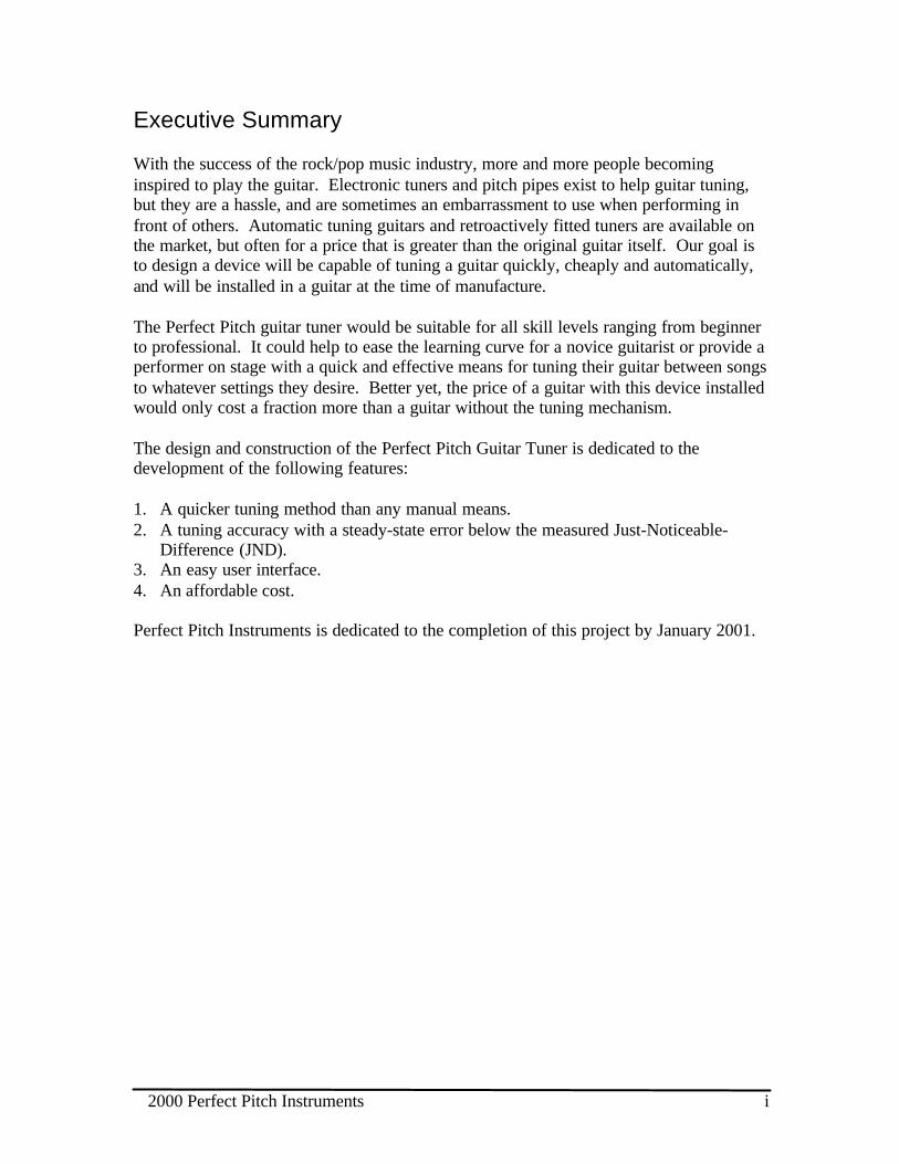
Executive Summary
With the success of the rock/pop music industry, more and more people becominginspired to play the guitar. Electronic tuners and pitch pipes exist to help guitar tuning,but they are a hassle, and are sometimes an embarrassment to use when performing infront of others. Automatic tuning guitars and retroactively fitted tuners are available onthe market, but often for a price that is greater than the original guitar itself. Our goal isto design a device will be capable of tuning a guitar quickly, cheaply and automatically,and will be installed in a guitar at the time of manufacture.
The Perfect Pitch guitar tuner would be suitable for all skill levels ranging from beginnerto professional. It could help to ease the learning curve for a novice guitarist or provide aperformer on stage with a quick and effective means for tuning their guitar between songsto whatever settings they desire. Better yet, the price of a guitar with this device installedwould only cost a fraction more than a guitar without the tuning mechanism.
The design and construction of the Perfect Pitch Guitar Tuner is dedicated to thedevelopment of the following features:
1. A quicker tuning method than any manual means.2. A tuning accuracy with a steady-state error below the measured Just-Noticeable-
Difference (JND).3. An easy user interface.4. An affordable cost.
Perfect Pitch Instruments is dedicated to the completion of this project by January 2001.
2000 Perfect Pitch Instruments ii
Table of ContentsEXECUTIVE SUMMARY........................................................................................................................................... I
INTRODUCTION......................................................................................................................................................... 1
1. SYSTEM OVERVIEW............................................................................................................................................ 2
2. PROGRAMMABLE USER INTERFACE........................................................................................................ 4
2.1 USER INTERFACE OVERVIEW..............................................................................................................................42.3 USER INTERFACE FIRMWARE ..............................................................................................................................8
3. THE SIGNAL INPUT PROCESSING UNIT............................................................................................. 9
3.1 FREQUENCY RESOLUTION OF INPUT SIGNAL....................................................................................................93.2 FREQUENCY TO VOLTAGE CONVERSION...........................................................................................................93.3 MICROPROCESSOR SELECTION .........................................................................................................................103.4 SIGNAL INPUT PROCESSING FIRMWARE ......................................................................................................11
4. MECHANICAL ACTUATING UNIT..............................................................................................................12
4.1 GUITAR AND BRIDGE..........................................................................................................................................124.2 COUPLING DEVICE ..............................................................................................................................................134.3 MOTORS................................................................................................................................................................144.4 DRIVER CIRCUITRY ............................................................................................................................................154.5 POWER SUPPLY ...................................................................................................................................................15
5. TESTING...................................................................................................................................................................15
5.1 PROGRAMMABLE USER INTERFACE .................................................................................................................155.2 SIGNAL INPUT PROCESSING UNIT .....................................................................................................................155.3 MECHANICAL ACTUATING UNIT ......................................................................................................................165.6 OVERALL SYSTEM ..............................................................................................................................................16
APPENDIX A.................................................................................................................................................................A
APPENDIX B..................................................................................................................................................................B
REFERENCES...............................................................................................................................................................C
List of FiguresFIGURE 1: GENERAL FEEDBACK MECHANISM..............................................................................................................2FIGURE 2. DESIGN SYSTEM OVERVIEW........................................................................................................................3FIGURE 3. FRONT-END OF USER INTERFACE ................................................................................................................4FIGURE 4. HARDWARE IMPLEMENTATION OF THE USER INTERFACE ......................................................................6FIGURE 5. HIGH-LEVEL BLOCK DIAGRAM OF USER INTERFACE ALGORITHM .......................................................8FIGURE 6. HIGH LEVEL BLOCK DIAGRAM OF THE SIGNAL INPUT PROCESSING ALGORITHM............................11FIGURE 7. FLOATING BRIDGE........................................................................................................................................12FIGURE 8. FINE TUNER (SIDE VIEW)............................................................................................................................13FIGURE 9. COUPLING DEVICE .......................................................................................................................................14
List of TablesTABLE 1. LCD STATUS DISPLAYS..................................................................................................................................5TABLE 2. LCD PIN-OUTS................................................................................................................................................7TABLE 3. PUSH BUTTON PIN CONNECTIONS..................................................................................................................7
2000 Perfect Pitch Instruments 1
Introduction
Very few people have the ability of “perfect pitch,” the ability to identify a note on themusical scale without having any reference note for comparison. Although the scientificand psychological aspects of perfect pitch are not well known, one thing is certain:whether perfect pitch is an inborn talent or an acquired trait, it need not be an essential orprerequisite for a musician.
The goal of our project is to design and develop an automatic electric guitar tuner thatwould eliminate the hassle involved with tuning a guitar manually. Although tuners existin the marketplace today, many are handheld requiring the user to pluck a string with onehand, hold the tuner with another hand, and adjust the tension in the strings with another.Clearly too many hands are needed, and the tuning process is unnecessarily timeconsuming. The few existing automatic guitar tuners cost thousands of dollars, and proveunaffordable for the general public.
We envision an automatic guitar tuner that would be installed in a guitar at the time ofmanufacture. This accessory will be capable of tuning a guitar with one simple strum, andwould be suitable for all skill levels ranging from beginner to professional. The tuner canhelp to ease the learning curve for a novice guitarist or provide a performer on stage witha quick and effective means for tuning their guitar between songs to whatever settingsthey desire. This implementation will also be affordable to most consumers.
This document outlines the high-level design specifications of this project, which includethe design details of the signal input processing unit, the mechanical actuating unit, andthe programmable user interface unit.
2000 Perfect Pitch Instruments 2
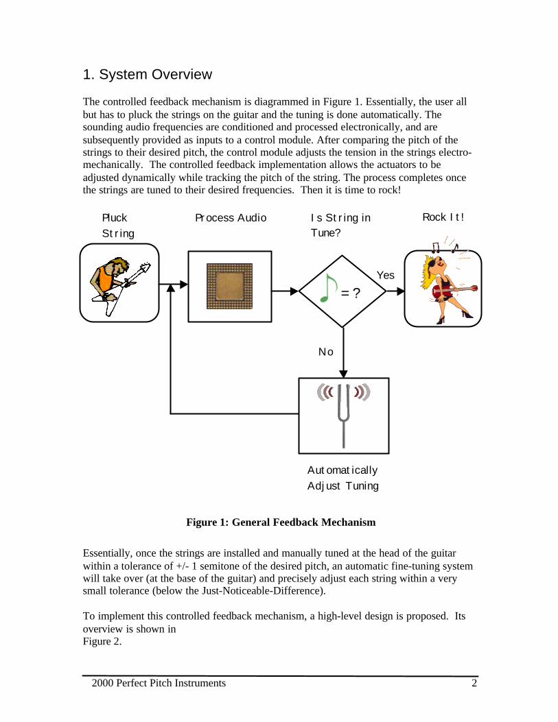
1. System Overview
The controlled feedback mechanism is diagrammed in Figure 1. Essentially, the user allbut has to pluck the strings on the guitar and the tuning is done automatically. Thesounding audio frequencies are conditioned and processed electronically, and aresubsequently provided as inputs to a control module. After comparing the pitch of thestrings to their desired pitch, the control module adjusts the tension in the strings electro-mechanically. The controlled feedback implementation allows the actuators to beadjusted dynamically while tracking the pitch of the string. The process completes oncethe strings are tuned to their desired frequencies. Then it is time to rock!
Figure 1: General Feedback Mechanism
Essentially, once the strings are installed and manually tuned at the head of the guitarwithin a tolerance of +/- 1 semitone of the desired pitch, an automatic fine-tuning systemwill take over (at the base of the guitar) and precisely adjust each string within a verysmall tolerance (below the Just-Noticeable-Difference).
To implement this controlled feedback mechanism, a high-level design is proposed. Itsoverview is shown inFigure 2.
PluckString
Process Audio Is String inTune?
= ?Yes
No
Rock It!
AutomaticallyAdjust Tuning
2000 Perfect Pitch Instruments 3
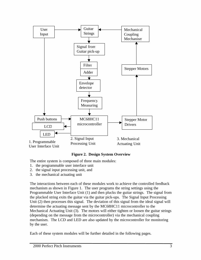
Figure 2. Design System Overview
The entire system is composed of three main modules:1. the programmable user interface unit2. the signal input processing unit, and3. the mechanical actuating unit
The interactions between each of these modules work to achieve the controlled feedbackmechanism as shown in Figure 1. The user programs the string settings using theProgrammable User Interface Unit (1) and then plucks the guitar strings. The signal fromthe plucked string exits the guitar via the guitar pick-ups. The Signal Input ProcessingUnit (2) then processes this signal. The deviation of this signal from the ideal signal willdetermine the actuating message sent by the MC68HC11 microcontroller to theMechanical Actuating Unit (3). The motors will either tighten or loosen the guitar strings(depending on the message from the microcontroller) via the mechanical couplingmechanism. The LCD and LED are also updated by the microcontroller for monitoringby the user.
Each of these system modules will be further detailed in the following pages.
UserInput
2. Signal InputProcessing Unit
Signal fromGuitar pick-up
FrequencyMeasuring
Envelopedetector
Filter
MC68HC11microcontroller
Stepper MotorDrivers
Stepper Motors
MechanicalCouplingMechanism
GuitarStrings
3. MechanicalActuating Unit1. Programmable
User Interface Unit
LCD
Push buttons
LED
Adder
2000 Perfect Pitch Instruments 4
2. Programmable User Interface
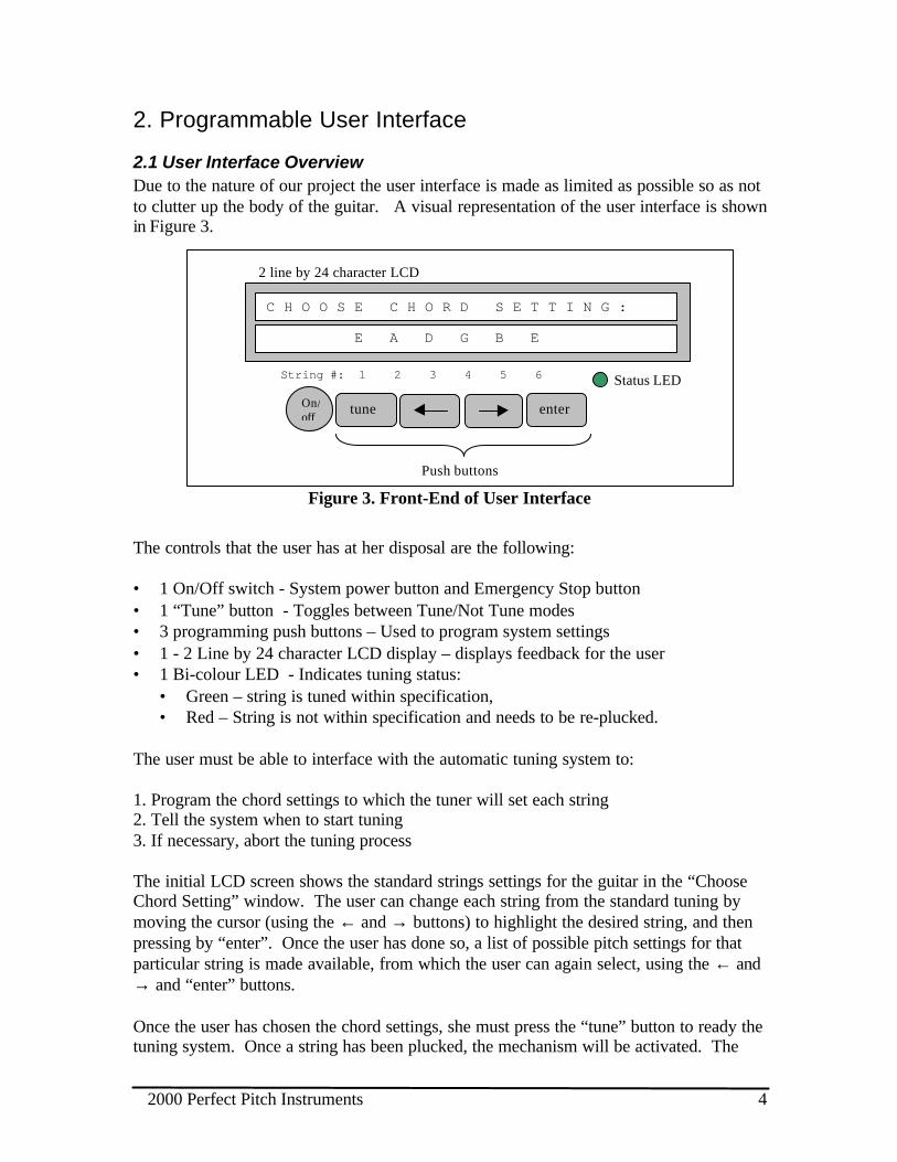
2.1 User Interface OverviewDue to the nature of our project the user interface is made as limited as possible so as notto clutter up the body of the guitar. A visual representation of the user interface is shownin Figure 3.
Figure 3. Front-End of User Interface
The controls that the user has at her disposal are the following:
• 1 On/Off switch - System power button and Emergency Stop button• 1 “Tune” button - Toggles between Tune/Not Tune modes• 3 programming push buttons – Used to program system settings• 1 - 2 Line by 24 character LCD display – displays feedback for the user• 1 Bi-colour LED - Indicates tuning status:
• Green – string is tuned within specification,• Red – String is not within specification and needs to be re-plucked.
The user must be able to interface with the automatic tuning system to:
1. Program the chord settings to which the tuner will set each string2. Tell the system when to start tuning3. If necessary, abort the tuning process
The initial LCD screen shows the standard strings settings for the guitar in the “ChooseChord Setting” window. The user can change each string from the standard tuning bymoving the cursor (using the ← and → buttons) to highlight the desired string, and thenpressing by “enter”. Once the user has done so, a list of possible pitch settings for thatparticular string is made available, from which the user can again select, using the ← and→ and “enter” buttons.
Once the user has chosen the chord settings, she must press the “tune” button to ready thetuning system. Once a string has been plucked, the mechanism will be activated. The
String #: 1 2 3 4 5 6
C H O O S E C H O R D S E T T I N G :
E A D G B E
2 line by 24 character LCD
Status LED
On/off
enter
Push buttons
tune

2000 Perfect Pitch Instruments 5
user can pluck any string, and the cursor on the LCD will highlight the string being tuned.Once each string has been tuned successfully, the LED will turn from red to green.
For any reason, the user can abort the tuning process by pressing the On/Off button at anytime.
Table 1 shows the possible status messages displayed by the LCD once the user haspressed the “tune” button.
Table 1. LCD status displays
Status Message System Status“Tuning in progress” The system is in tuning mode; no new data
entry will be accepted“String #X successfully tuned” The system has exited tuning mode, with the
string in tune.“Pluck String Again” The system is still in tuning mode and requires
the user to pluck the string again.“Error: string too tight” The system detect that a string may snap if
tightened any further. The user either haschosen a poor string setting, or the string is oldand must be changed.
“Error: motor jam” The motor is not rotating when it should.“Error: tuning failed, system failure” The system has experienced an electrical or
mechanical failure.“Error: too many strings” The system detects that more than one string
was plucked at the same time, and not action istaken.
“Error: tuning failed, check string” After 5 attempts, the system aborts the tuningprocess and the user must check the stringmanually.
The user has the option of resetting the system at any time by pressing the On/Off buttontwice.
2000 Perfect Pitch Instruments 6
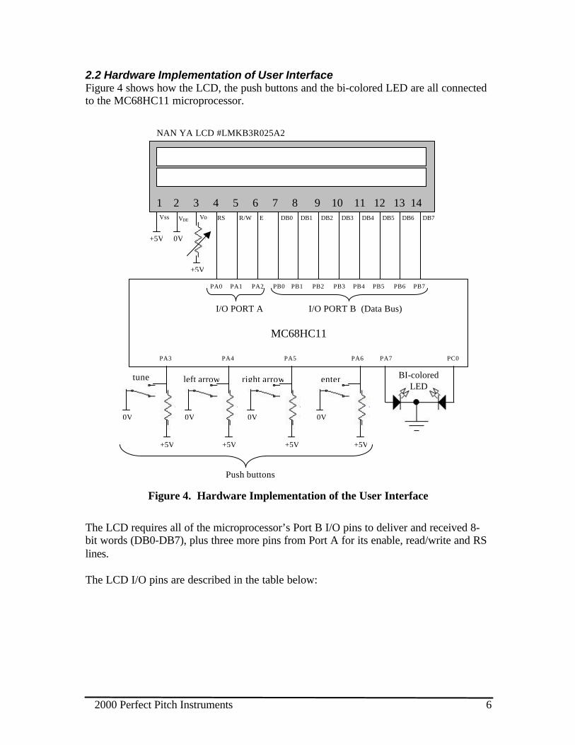
2.2 Hardware Implementation of User InterfaceFigure 4 shows how the LCD, the push buttons and the bi-colored LED are all connectedto the MC68HC11 microprocessor.
Figure 4. Hardware Implementation of the User Interface
The LCD requires all of the microprocessor’s Port B I/O pins to deliver and received 8-bit words (DB0-DB7), plus three more pins from Port A for its enable, read/write and RSlines.
The LCD I/O pins are described in the table below:
1 2 3 4 5 6 7 8 9 10 11 12 13 14
NAN YA LCD #LMKB3R025A2
+5V 0V
+5V
RS R/W E DB0 DB1 DB2 DB3 DB4 DB5 DB6 DB7
PA0 PA1 PA2 PB0 PB1 PB2 PB3 PB4 PB5 PB6 PB7
I/O PORT A I/O PORT B (Data Bus)
MC68HC11
PA3 PA4 PA5 PA6 PA7 PC0
+5V
0V
tune
+5V
0V
left arrow
+5V
0V
right arrow
+5V
0V
enter
Push buttons
BI-coloredLED
Vss VDD Vo
2000 Perfect Pitch Instruments 7
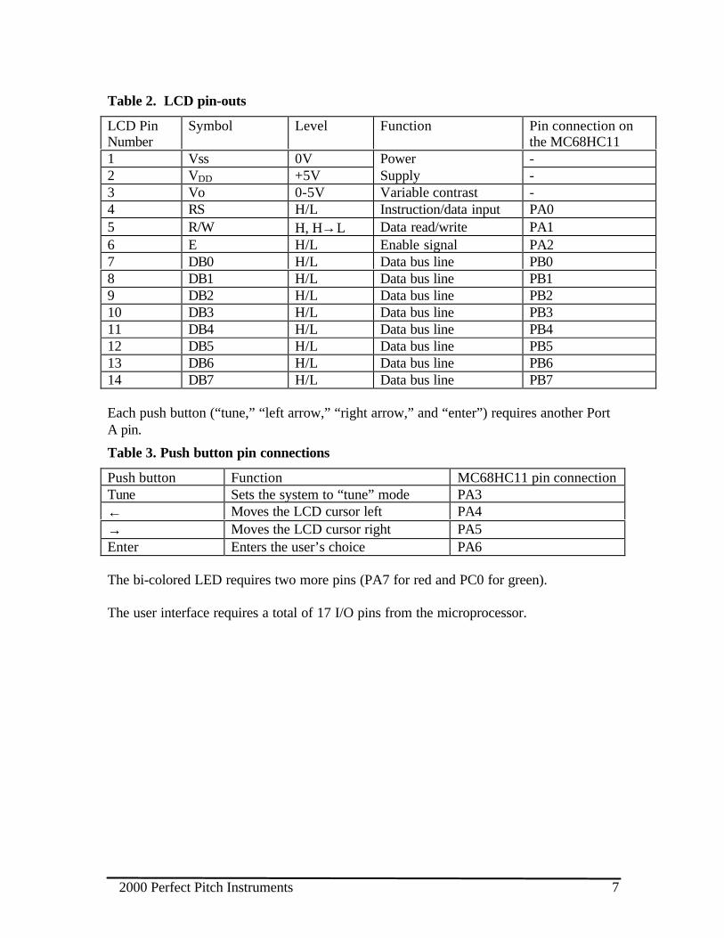
Table 2. LCD pin-outs
LCD PinNumber
Symbol Level Function Pin connection onthe MC68HC11
1 Vss 0V -2 VDD +5V
PowerSupply -
3 Vo 0-5V Variable contrast -4 RS H/L Instruction/data input PA05 R/W H, H→L Data read/write PA16 E H/L Enable signal PA27 DB0 H/L Data bus line PB08 DB1 H/L Data bus line PB19 DB2 H/L Data bus line PB210 DB3 H/L Data bus line PB311 DB4 H/L Data bus line PB412 DB5 H/L Data bus line PB513 DB6 H/L Data bus line PB614 DB7 H/L Data bus line PB7
Each push button (“tune,” “left arrow,” “right arrow,” and “enter”) requires another PortA pin.
Table 3. Push button pin connections
Push button Function MC68HC11 pin connectionTune Sets the system to “tune” mode PA3← Moves the LCD cursor left PA4→ Moves the LCD cursor right PA5Enter Enters the user’s choice PA6
The bi-colored LED requires two more pins (PA7 for red and PC0 for green).
The user interface requires a total of 17 I/O pins from the microprocessor.
2000 Perfect Pitch Instruments 8
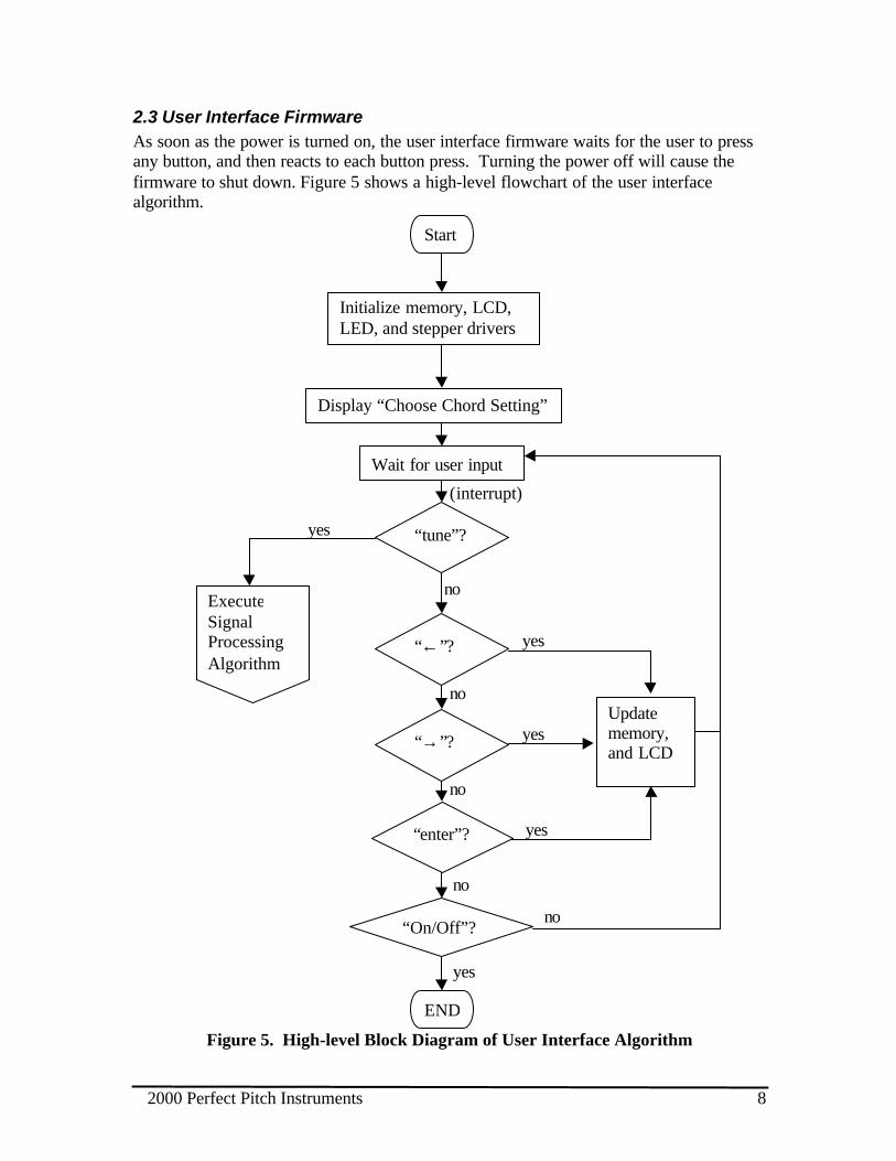
2.3 User Interface FirmwareAs soon as the power is turned on, the user interface firmware waits for the user to pressany button, and then reacts to each button press. Turning the power off will cause thefirmware to shut down. Figure 5 shows a high-level flowchart of the user interfacealgorithm.
Figure 5. High-level Block Diagram of User Interface Algorithm
“→”?
“enter”?
no
Updatememory,and LCD
yes
yes
“On/Off”?
no
yes
no
END
no
yes
“←”? yes
ExecuteSignalProcessingAlgorithm
Start
Initialize memory, LCD,LED, and stepper drivers
Display “Choose Chord Setting”
Wait for user input
“tune”?
(interrupt)
no

2000 Perfect Pitch Instruments 9
3. The Signal Input Processing Unit
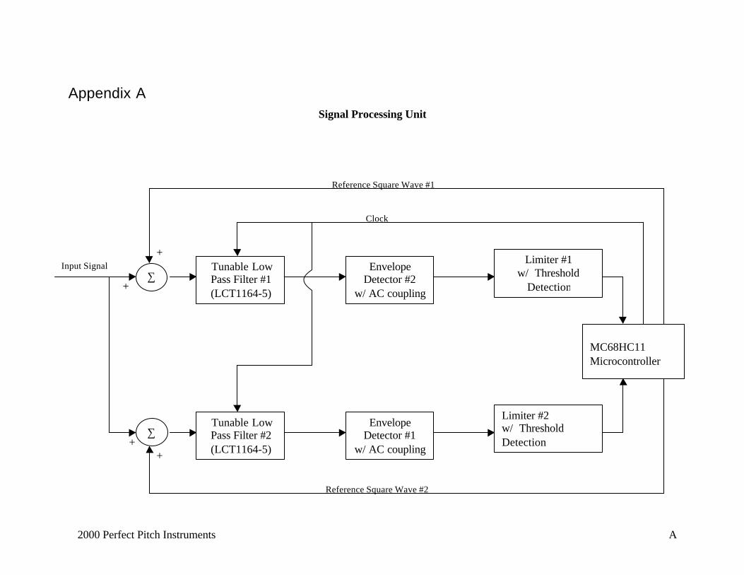
A block diagram implementation of the Signal Processing Unit is given in Appendix A.The unit processes the input signal from the guitar pickups in two parallel operations. Theentire process relies on “beat detection”, and consists of frequency resolution andfrequency to voltage conversion. The need for two parallel units will soon becomeapparent.
3.1 Frequency Resolution of Input Signal
To resolve the frequency of the input signal, we need to perform the following
1) Modulation2) Filtering3) Envelope Detection4) Limiter
Modulation involves adding a Reference Square Wave to the Input Signal. The modulatedsignal then passes through the clock tunable low pass filter (having a cuttoff frequencyclose to the desired string frequency) to remove harmonics from the input signal, as wellas from the additive square wave. The output of the filter is a modulated signal with asinusiodal envelope having a frequency equal to the difference between the ReferenceSquare Wave and the Input Signal. To detect this envelope, we have implemented andenvelope detector consisting of a simple diode, and RC circuit. The DC component of thesignal if removed through a coupling capacitor. The output of the envelope detector isthen fed into a limiter circuit that squares up the input signal as long as its amplitude isabove a predetermined threshold level. Thus the limiter output is a square wave withconstant amplitude, and frequency equal to the difference between the Reference SquareWave and the Input Signal.
3.2 Frequency to Voltage Conversion
Since we want to determine if the string should be tuned up or tuned down, we need tohave two parallel units as is shown in the block diagram. The frequency of ReferenceSquare Wave #1 is set slightly lower than the desired frequency and the frequency ofReference Square Wave #2 set slightly above the desired frequency.
The limiter outputs are connected to the input compare channel of the MC68HC11microcontroller. The microcontroller is configured such that it generates an interrupt andevery time a zero crossing on the input signal is detected. The interrupt service routinelatches the local timer value into memory, and thus the frequency of the limiter outputsignal can be measured. If the frequency of the signal of Limiter #1 is greater than thefrequency of the signal of Limiter #2, we conclude that the string needs to be tuned downand vise versa. The microcontroller now knows which direction the motors should turnin, and by what amount.
2000 Perfect Pitch Instruments 10
3.3 Microprocessor Selection
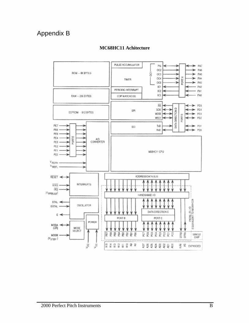
Since we decided not to process our signals digitally early on, we could rule out a digitalsignal processor fairly soon in the design process. It was decided that the Perfect PitchAutomatic Guitar Tuner called for a microprocessor that would be able to process anincoming signal, control a user interface on an LCD, and actuate the motors that wouldultimately tune the guitar strings. Various microcontrollers were considered, but the onechosen was an E series Motorola 68HC11. Our rationale was based upon availability (wewere given the chip for free), familiarity (all our group members have had pastexperience with the chip), and capability to meet all our processing needs. The list belowhighlights features that are important and beneficial to our system.
• M68HC11 CPU
• 512 Bytes of On-Chip RAM and 2048 bytes of EEPROM
• 8-Channel 8-Bit Analog-to-Digital (A/D) Converter
• 16-Bit Timer System
o Three Input Capture (IC) Channels
o Four Output Compare (OC) Channels
• 8-Bit Pulse Accumulator
• Real-Time Interrupt Circuit
• 38 General-Purpose Input/Output (I/O) Pins
o 16 Bi-directional I/O Pins
o 11 Input-Only Pins
o 11 Output-Only Pins
A diagram of the 68HC11 architecture is included in Appendix B.
2000 Perfect Pitch Instruments 11
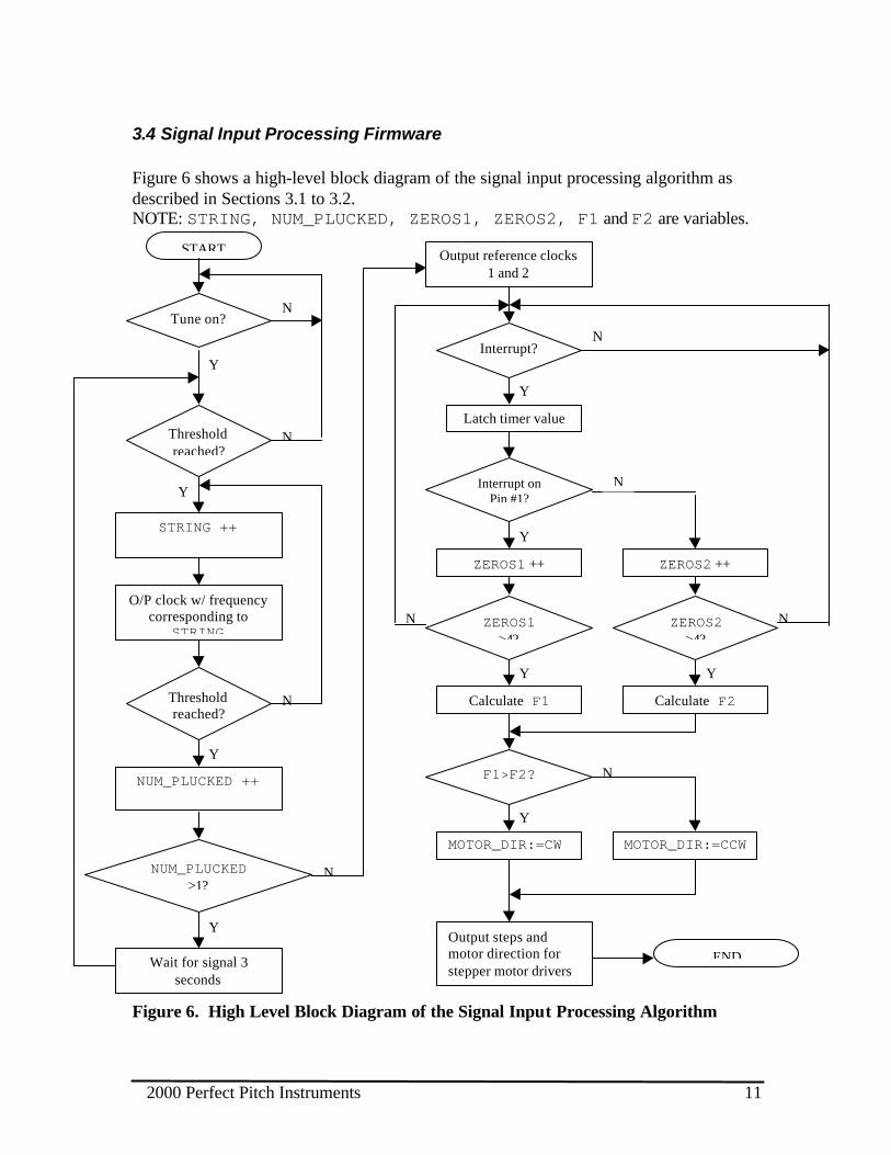
3.4 Signal Input Processing Firmware
Figure 6 shows a high-level block diagram of the signal input processing algorithm asdescribed in Sections 3.1 to 3.2.NOTE: STRING, NUM_PLUCKED, ZEROS1, ZEROS2, F1 and F2 are variables.
Figure 6. High Level Block Diagram of the Signal Input Processing Algorithm
Tune on?
START
N
MOTOR_DIR:=CW MOTOR_DIR:=CCW
Y
NF1>F2?
YY
N NZEROS1>4?
ZEROS2>4?
Calculate F2Calculate F1
Output steps andmotor direction forstepper motor drivers
END
Y
Y
N
N
NUM_PLUCKED ++
NUM_PLUCKED>1?
Wait for signal 3seconds
Y
STRING ++
O/P clock w/ frequencycorresponding to
STRING
Thresholdreached?
N
Y
Thresholdreached?
Y
ZEROS1 ++ ZEROS2 ++
Y
Output reference clocks1 and 2
Interrupt?
Latch timer value
Interrupt onPin #1?
N
N

2000 Perfect Pitch Instruments 12
4. Mechanical Actuating Unit
4.1 Guitar and Bridge
The electric guitar we selected is a 3 pick-up guitar (2 single coil, 1 Humbucker)complete with a Kahler floating bridge (similar to a Floyd Rose). After some preliminarydesign work, it was decided that the most suitable way to interface motors to the guitarstrings for our purposes is to use a pre-manufactured floating bridge.
The most common embodiment of the floating bridge is the patented Floyd Rose FloatingBridge, in which the entire bridge pivots about two vertical posts aligned across the bodyof the guitar (i.e. perpendicular to the strings). The term “floating” refers to the fact thatthe bridge is held in place by the counter-balancing forces of the six tensioned strings,which travel along the top of the body, and 2-3 tensioned springs traveling underneath thebody Figure 7. The two pulling forces cause the bridge to balance in a somewhathorizontal position. A lever attached to the bridge (often called a tremolo bar or whamibar), permits the guitarist to pivot the bridge around the vertical posts by exerting torqueon the lever. This causes a change in string pitch, as the tension in all strings is eitherincreased or decreased.
Figure 7. Floating Bridge
The guitar strings tend to go out of tune when repeatedly subjected to strains caused bythe yanking of the tremolo bar. In order to reduce the susceptibility of the strings to de-
2000 Perfect Pitch Instruments 13
tuning, a locking nut, consisting of a simple clamping mechanism is installed at the top ofthe guitar neck. This clamps the strings in place so that the tuning pegs in the head of theguitar do not unwind. When the nut is locked, however, the guitarist is unable to tune herguitar using the conventional tuning pegs, therefore, a secondary set of tuning pegs,called “fine tuners” are installed on the floating bridge itself, allowing the guitarist totune her guitar after the nut has been locked.
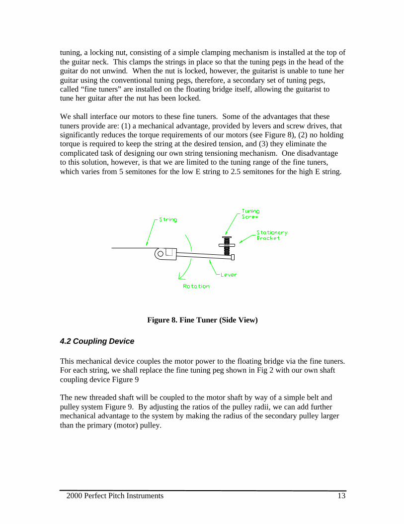
We shall interface our motors to these fine tuners. Some of the advantages that thesetuners provide are: (1) a mechanical advantage, provided by levers and screw drives, thatsignificantly reduces the torque requirements of our motors (see Figure 8), (2) no holdingtorque is required to keep the string at the desired tension, and (3) they eliminate thecomplicated task of designing our own string tensioning mechanism. One disadvantageto this solution, however, is that we are limited to the tuning range of the fine tuners,which varies from 5 semitones for the low E string to 2.5 semitones for the high E string.
Figure 8. Fine Tuner (Side View)
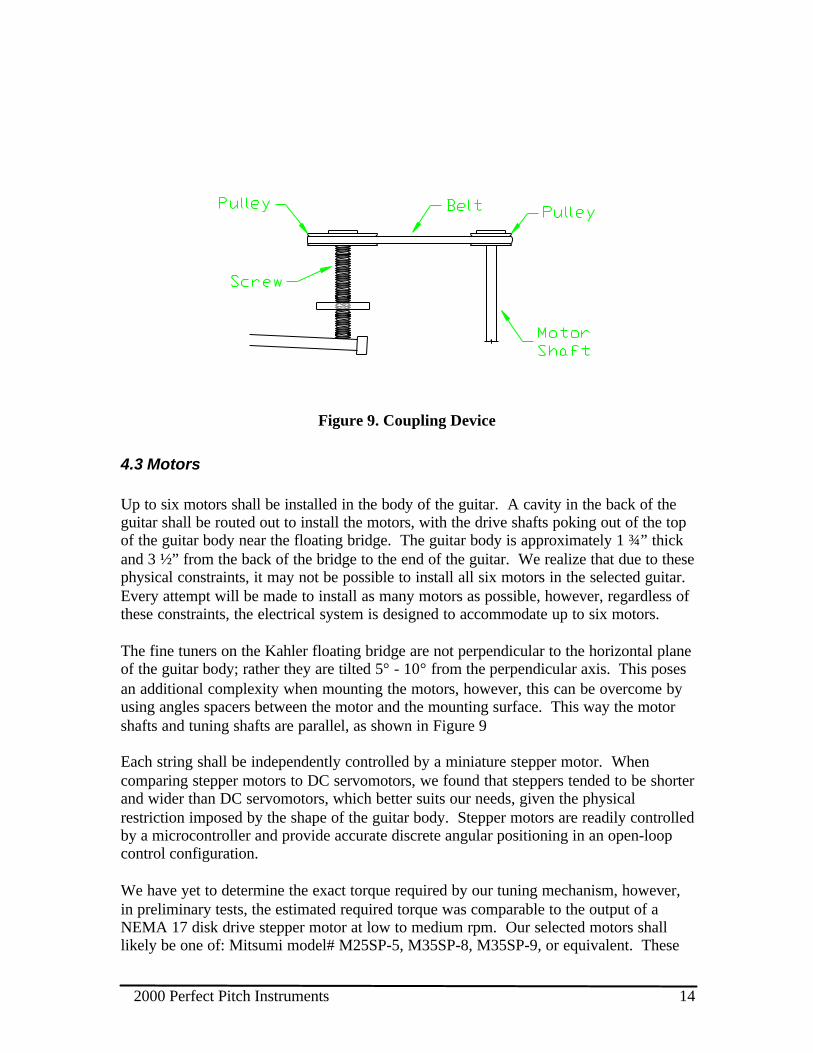
4.2 Coupling Device
This mechanical device couples the motor power to the floating bridge via the fine tuners.For each string, we shall replace the fine tuning peg shown in Fig 2 with our own shaftcoupling device Figure 9
The new threaded shaft will be coupled to the motor shaft by way of a simple belt andpulley system Figure 9. By adjusting the ratios of the pulley radii, we can add furthermechanical advantage to the system by making the radius of the secondary pulley largerthan the primary (motor) pulley.
2000 Perfect Pitch Instruments 14
Figure 9. Coupling Device
4.3 Motors
Up to six motors shall be installed in the body of the guitar. A cavity in the back of theguitar shall be routed out to install the motors, with the drive shafts poking out of the topof the guitar body near the floating bridge. The guitar body is approximately 1 ¾” thickand 3 ½” from the back of the bridge to the end of the guitar. We realize that due to thesephysical constraints, it may not be possible to install all six motors in the selected guitar.Every attempt will be made to install as many motors as possible, however, regardless ofthese constraints, the electrical system is designed to accommodate up to six motors.
The fine tuners on the Kahler floating bridge are not perpendicular to the horizontal planeof the guitar body; rather they are tilted 5° - 10° from the perpendicular axis. This posesan additional complexity when mounting the motors, however, this can be overcome byusing angles spacers between the motor and the mounting surface. This way the motorshafts and tuning shafts are parallel, as shown in Figure 9
Each string shall be independently controlled by a miniature stepper motor. Whencomparing stepper motors to DC servomotors, we found that steppers tended to be shorterand wider than DC servomotors, which better suits our needs, given the physicalrestriction imposed by the shape of the guitar body. Stepper motors are readily controlledby a microcontroller and provide accurate discrete angular positioning in an open-loopcontrol configuration.
We have yet to determine the exact torque required by our tuning mechanism, however,in preliminary tests, the estimated required torque was comparable to the output of aNEMA 17 disk drive stepper motor at low to medium rpm. Our selected motors shalllikely be one of: Mitsumi model# M25SP-5, M35SP-8, M35SP-9, or equivalent. These
2000 Perfect Pitch Instruments 15
are all high performance motors, with high torque outputs per physical size. They haveangular resolutions of 24 or 48 steps/rev, which is plenty for our task, however, theresolution can be increased by adjusting the ratio of pulley radii described above.
4.4 Driver Circuitry
As mentioned earlier, our design calls for six stepper motors to be controlledindependently. In order do this effectively with our HC11, we shall use two 2-8 decodersto route the output pulse control signals from the HC11 to one of the six stepper motors.Additional I/O from the HC11 will be required to control the decoders.
The six pairs of outputs from the decoders ICs will be amplified by power transistors todrive the motors. These shall likely be in a Darlington configuration.
4.5 Power Supply
The automatic guitar tuner will run off of a standard wall socket power supply using a120VAC to 24 VDC adaptor. The required voltages for different components (i.e.24VDC for motors, 5VDC for LCD, microprocessor, etc.) can be obtained by steppingdown the 24 VDC using voltage dividers and regulators.
5. Testing
5.1 Programmable User InterfaceThe user interface will be tested using the following procedure. The signal processingprocedures in the HC11 will be preprogrammed to return the appropriate values to the UI.
1. Turn the system on using the power switch.2. Using the buttons and LCD, program the tuner to standard tuning and select a string.3. Set the “Tune” switch.4. Trigger the threshold externally. Verify that the LED illuminates red, then green.5. Turn tune mode off.6. Program a different tuning, and repeat steps 3 through 5.7. Turn the system off.
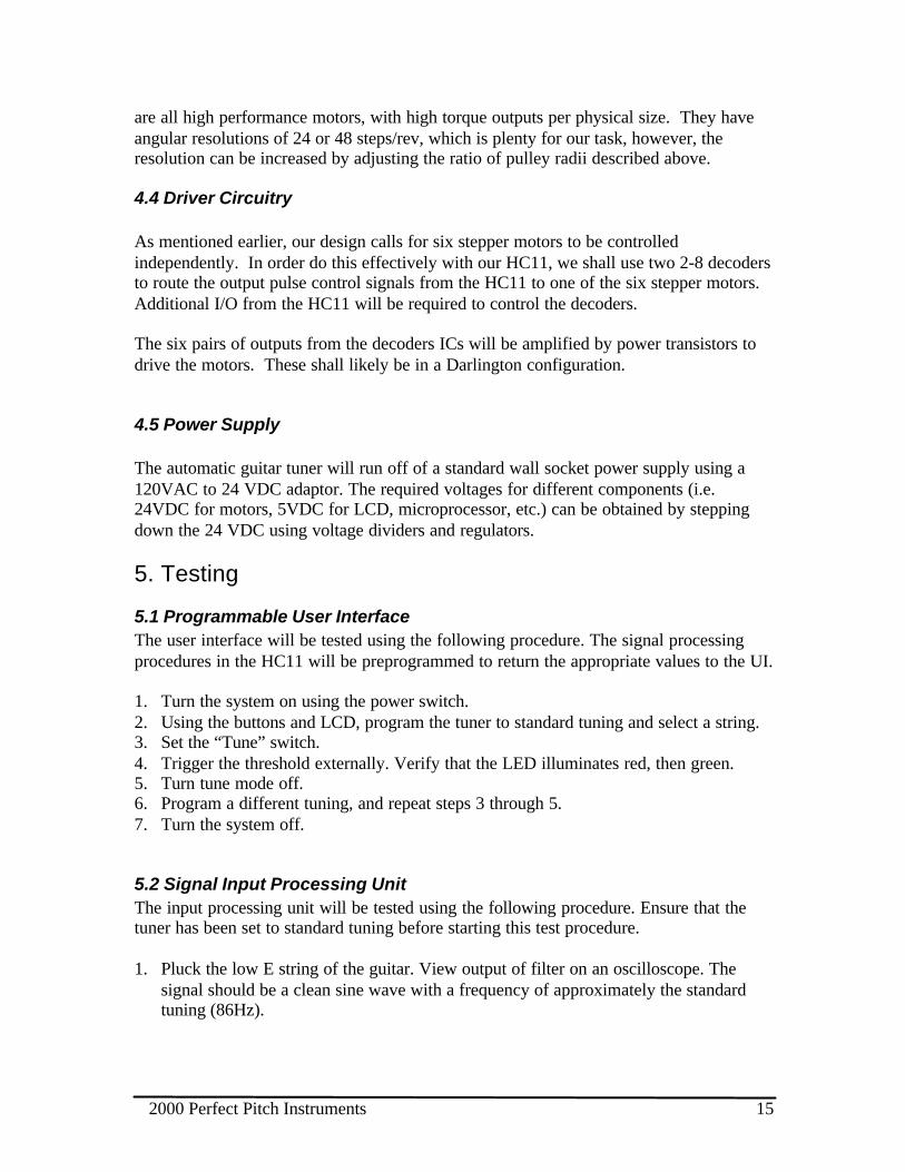
5.2 Signal Input Processing UnitThe input processing unit will be tested using the following procedure. Ensure that thetuner has been set to standard tuning before starting this test procedure.
1. Pluck the low E string of the guitar. View output of filter on an oscilloscope. Thesignal should be a clean sine wave with a frequency of approximately the standardtuning (86Hz).
2000 Perfect Pitch Instruments 16
2. Connect the oscilloscope to the signal conditioning stage output. Pluck the stringagain and observe the output signal. Verify that the signal is a low frequency squarewave.
3. Tune the low E string to a frequency slightly lower than the standard tuning. Connectthe oscilloscope to the output of the microprocessor (output to the mechanical unit).Pluck the string and view the output. Verify that the output signal is the one requiredto tighten the string.
4. Tune the string slightly higher than the standard tuning and repeat step 3. Verify thatthe output signal will loosen the string.
5. Repeat steps 1 through 4 for each string.
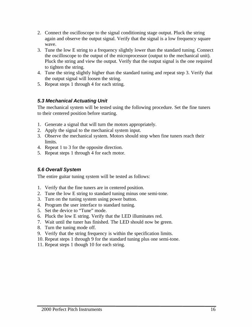
5.3 Mechanical Actuating UnitThe mechanical system will be tested using the following procedure. Set the fine tunersto their centered position before starting.
1. Generate a signal that will turn the motors appropriately.2. Apply the signal to the mechanical system input.3. Observe the mechanical system. Motors should stop when fine tuners reach their
limits.4. Repeat 1 to 3 for the opposite direction.5. Repeat steps 1 through 4 for each motor.
5.6 Overall SystemThe entire guitar tuning system will be tested as follows:
1. Verify that the fine tuners are in centered position.2. Tune the low E string to standard tuning minus one semi-tone.3. Turn on the tuning system using power button.4. Program the user interface to standard tuning.5. Set the device to “Tune” mode.6. Pluck the low E string. Verify that the LED illuminates red.7. Wait until the tuner has finished. The LED should now be green.8. Turn the tuning mode off.9. Verify that the string frequency is within the specification limits.10. Repeat steps 1 through 9 for the standard tuning plus one semi-tone.11. Repeat steps 1 though 10 for each string.

2000 Perfect Pitch Instruments 17
This page is left intentionally blank.
2000 Perfect Pitch Instruments A
Appendix ASignal Processing Unit
Reference Square Wave #2
Tunable LowPass Filter #1(LCT1164-5)
∑
+
+
EnvelopeDetector #2
w/ AC coupling
Limiter #1w/ Threshold
Detection
∑
++
EnvelopeDetector #1
w/ AC coupling
Limiter #2w/ ThresholdDetection
MC68HC11Microcontroller
Reference Square Wave #1
Clock
Input Signal
Tunable LowPass Filter #2(LCT1164-5)
2000 Perfect Pitch Instruments B
Appendix B
MC68HC11 Achitecture
2000 Perfect Pitch Instruments C
References
[1] Mark Products Corp, LMKB3R025A2 Liquid Crystal Display Data Sheet[2] Motorola Corp, MC68HC11 Handbook