Embed Size (px)
Citation preview

Perform Control Test

Check for Consistent Liquid Temperatures
Entering and Leaving Liquid Temperatures should be close when the water pumps are on but the compressor is not running
Calibrate Pressure Transducers

Pressure Transducer Calibration
Leaving Chilled Liquid (Optional)
Entering Condenser Liquid (Optional)
Leaving Chilled Liquid (Optional)
Entering Chilled Liquid (Optional)
Condenser Pressure
Cooler Pressure
Discharge Pressure
Oil Pressure Leaving Filter
Oil Sump Pressure
Calibrate in place with Condenser Liquid Pump off
Calibrate in place with Condenser Liquid Pump off
Calibrate in place with Chilled Liquid Pump off
Calibrate in place with Chilled Liquid Pump off
Calibrate at 0 PSIOptional High Pressure Calibration
-
Calibrate at 0 PSIOptional High Pressure Calibration
-
Calibrate at 0 PSIOptional High Pressure Calibration
-
-Calibrate in place with Oil Pump off
-Calibrate in place with Oil Pump off
Pressure SensorsDelta P Sensors
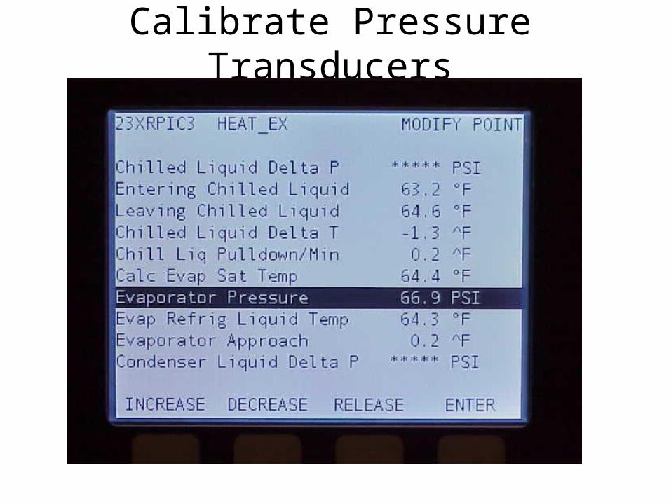
Check for Consistent Refrigerant Temperatures
Refrigerant Temperatures should be close when the isolation valves are open, the water temperatures are stable, and the chiller is not running

Perform Control Test
Pumps: Carrier Controls must be able to independently energize the Cooler and Condenser Liquid Pumps for Freeze Protection
Oil Reclaim Output: Varies 2-20 mA oil reclaim output from CCM J8-3 and J8-4 with power removed from oil reclaim motor.
Discrete Outputs: Cycles Heater Relays, HGBP, Alarm Relay, VFD Cooling Solenoid, and Shunt Trip
Head Pressure Output: Varies Control Center TB1–17 & TB1-18 output between 4 and 20 mA

ICVC Software Version Number
ICVC Software Version in ICVC Configuration Screen

VFD Software Version Number
Gateway, Inverter, and Rectifier VFD Software Versions in VFD_STAT Screen

Check Optional Pumpout ControlsContactor SwitchFuses
Terminal Strip
Transformer
See 19XR-6SI Pumpout Installation, Operating & Maintenance Instruction Manual
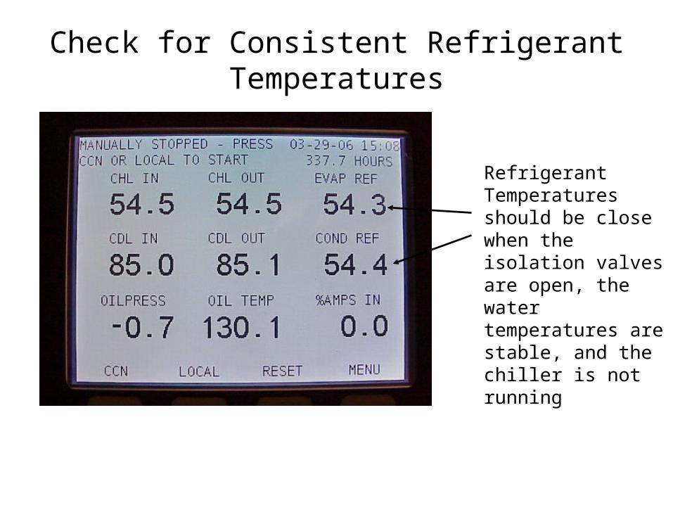
Check Isolation Valves
Oil Pump Isolation Valve
Oil Filter Isolation Valve
Oil Pressure Regulator Isolation Valve
Vaporizer Condenser Gas
Discharge Isolation Valve

Check Isolation Valves
Cooler Inlet Isolation Valve
Hot Gas Bypass Isolation Valve
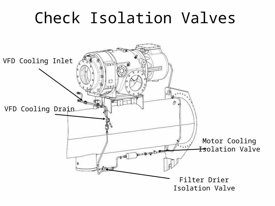
Check Isolation Valves
Filter Drier Isolation Valve
Motor Cooling Isolation Valve
VFD Cooling Inlet
VFD Cooling Drain

Charge Refrigerant into Chiller
Charge refrigerant through charging valve. Charging refrigerant through the service valve on the refrigerant liquid line may force debris into the float valve
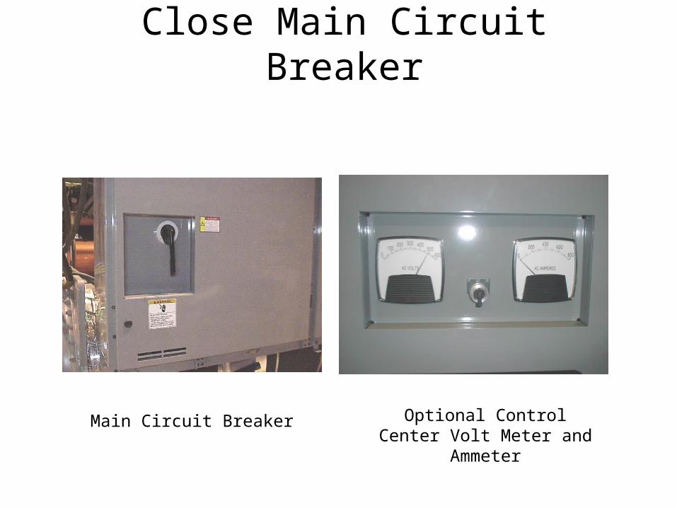
Close Main Circuit Breaker
Optional Control Center Volt Meter and Ammeter
Main Circuit Breaker
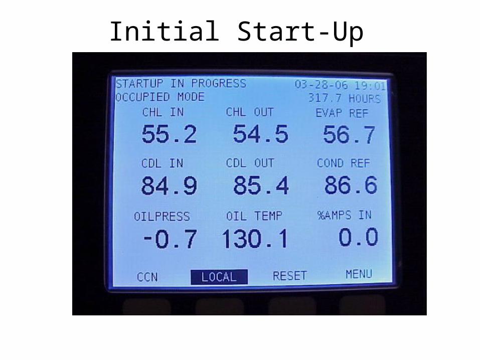
Initial Start-Up
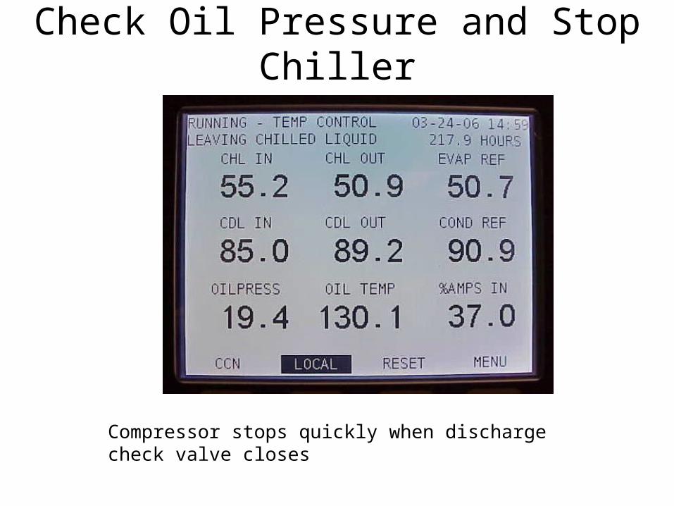
Check Oil Pressure and Stop Chiller
Compressor stops quickly when discharge check valve closes

Start Chiller and Monitor Operation
• Oil Reclaim System• Motor Cooling• VFD • Chiller Alerts
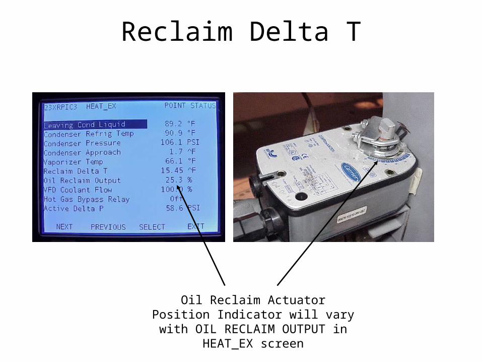
Reclaim Delta T
Oil Reclaim Actuator Position Indicator will vary with OIL RECLAIM OUTPUT
in HEAT_EX screen

Vaporizer Sight GlassBoiling refrigerant can be observed around vaporizer
tubes when oil reclaim actuator is open

Vaporizer Drain Sight Glass
Ripples in Oil Level should be observed when oil drains into
sump

Oil Level
Oil level may cover the Oil Sump Sight Glass before start-up and fall below the bottom of the Oil Sump Sight Glass shortly after start-up.
Oil level stabilizes after the first 24
hours of operation
Oil Sump Sight Glass
Check strainer housing sight glass if oil level falls below oil sump sight glass
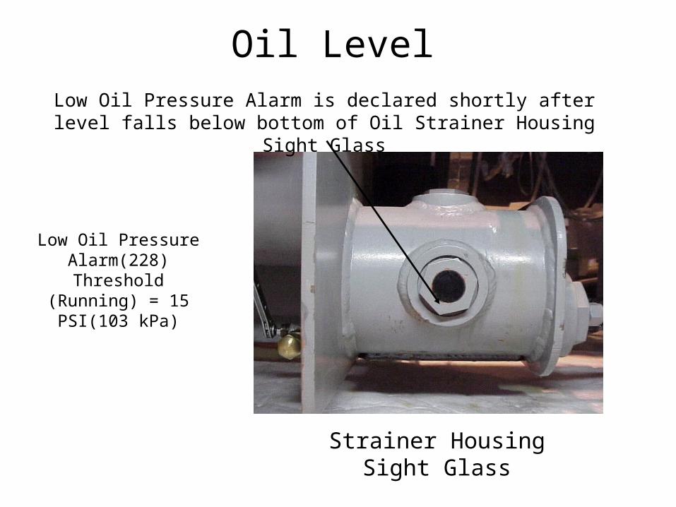
Oil LevelLow Oil Pressure Alarm is declared shortly after level falls below bottom of
Oil Strainer Housing Sight Glass
Strainer Housing Sight Glass
Low Oil Pressure Alarm(228) Threshold
(Running) = 15 PSI(103 kPa)

Discharge Superheat
Discharge Superheat may be as low as 1 deg F (0.6 C) at start-up.
Discharge superheat will climb as oil is recovered from the cooler.

Motor Cooling Sight Glass
Steady Refrigerant Flow should be Observed
High Motor Temperature Alarm(233) Threshold = 244 deg F(118 C)

Inverter and Rectifier Temperatures
High Temperature Override Configurable 155 – 170 deg F (68 – 77 deg C)
High Temperature Alarm Threshold(218, 219) Variable – Calculated by the VFD
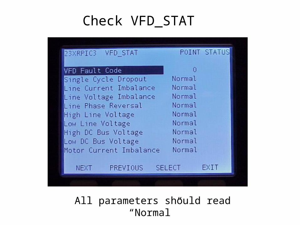
Check VFD_STAT
All parameters should read “Normal”
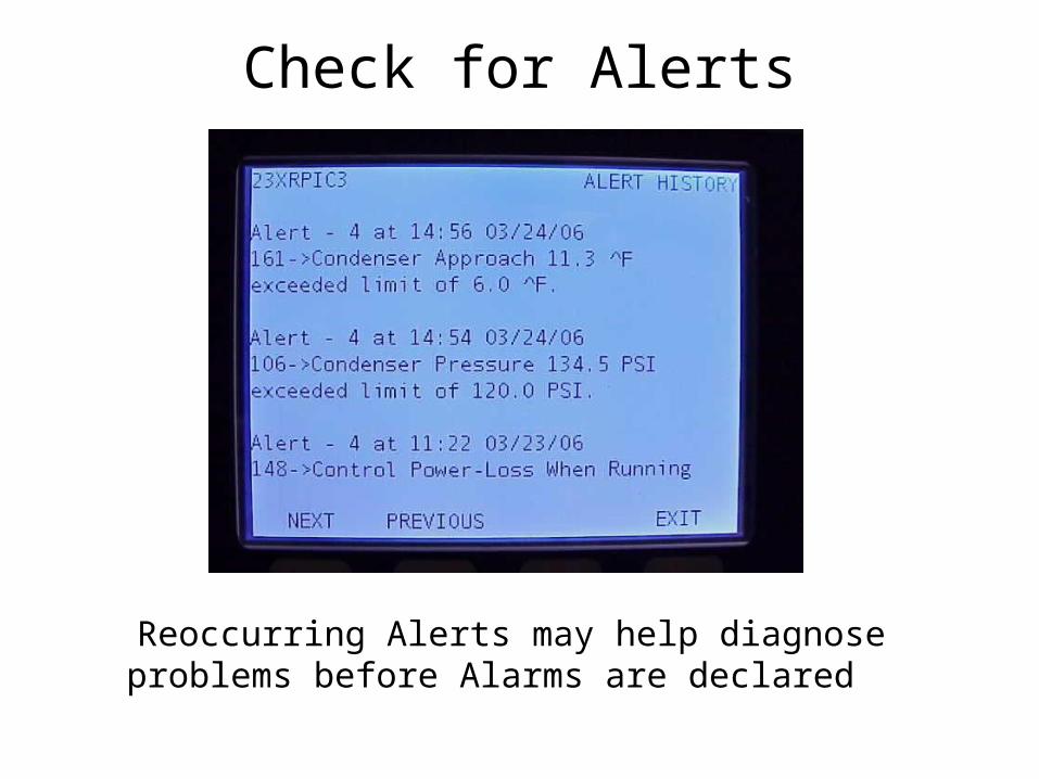
Check for Alerts
Reoccurring Alerts may help diagnose problems before Alarms are declared

Instruct Customer Operator
• Cooler & Condenser• Optional Pumpout and Storage Tank• Motor/Compressor Assembly• Compressor Lubrication System• Control System

Instruct Customer Operator
• Auxiliary Equipment• Chiller Cycles• Safety Devices and Procedures• Check Operator Knowledge• Review Start-Up Operation &
Maintenance Manual

Rockwell LiquiFlo II Start-up Registration
Only service technicians that have completed Rockwell LiquiFlo II Tier I Certification Training are to start the related drives.
•Once started, the LiquiFLo 2 VFD is to be registered on the Rockwell WARP Site
• Standard Warranty is One Year. If the LiquiFlo 2 is started by a Certified Technician, the VFD Parts Warranty is extended to Two Years from Start-up.
• In order to register VFD with Rockwell, Control Center and Power Module Model and Serial Numbers are needed from labels located inside the Control Center.

How to Register a Startupwww.automation.rockwell.com/warp
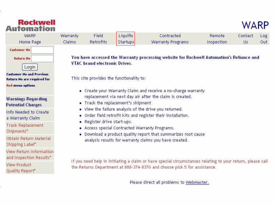

Enter Login ID and Password of LiquiFlo 2
Certified Technician


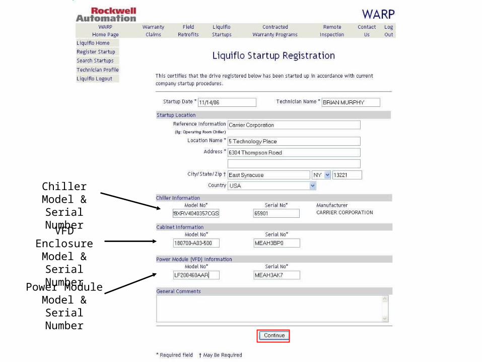
Power Module Model & Serial
Number
Chiller Model & Serial Number
VFD Enclosure Model & Serial
Number
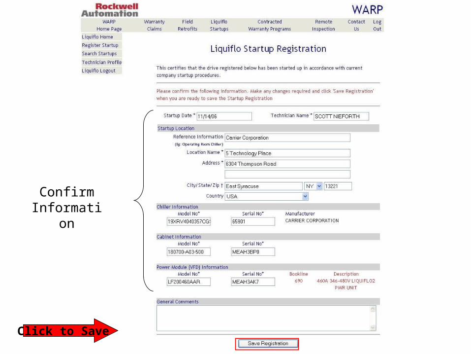
Confirm Information
Click to Save

Registration Acknowledged

How to Search for Startups

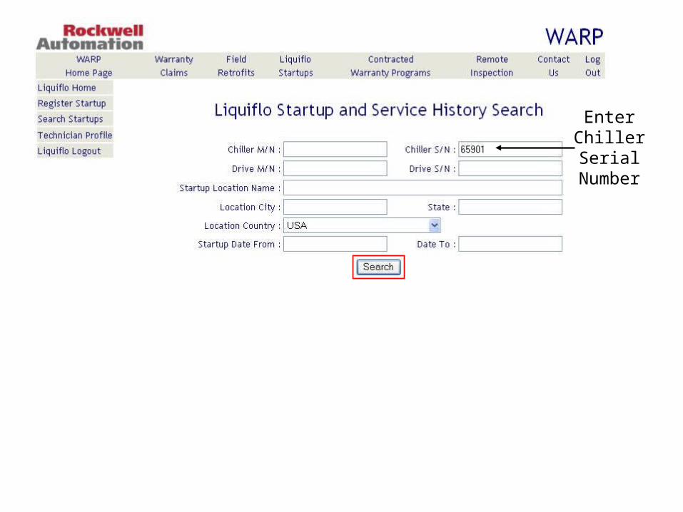
Enter Chiller Serial
Number

Click to View

Parts-Only Warranty Two
Years from Startup Date