Embed Size (px)
Citation preview
i
A Report on
Performance & Emission Analysis of blends of Karanja
Methyl Ester in a Compression Ignition Engine
A REPORT SUBMITTED IN PARTIAL FULFILLMENT OF THE
REQUIREMENTS FOR THE DEGREE OF
BACHELOR OF TECHNOLOGY (CHEMICAL ENGINEERING)
Submitted by-
Saswat Rath
Roll No: 107CH020
Under the guidance of:-
Prof. (Dr.) R.K.Singh
National Institute of Technology
Rourkela
Orissa-769008
brought to you by COREView metadata, citation and similar papers at core.ac.uk
provided by ethesis@nitr
ii
National Institute of Technology
Rourkela
CERTIFICATE
This is to certify that that the work in this thesis report entitled “Performance & Emission
Analysis of blends of Karanja Methyl Ester in a Compression Ignition Engine” submitted
by Saswat Rath in partial fulfilment of the requirements for the degree of Bachelor of
Technology in Chemical Engineering, Session 2007-2011, in the department of Chemical
Engineering, National Institute of Technology, Rourkela, is an authentic work carried out by him
under my supervision and guidance.
To the best of my knowledge the matter embodied in the report has not been submitted to any
other University /Institute for the award of any degree.
Date: Dr. R.K. Singh
Department of Chemical Engineering
National Institute of Technology
Rourkela – 769008
iii
ACKNOWLEDGEMENT
I wish to express my sincere thanks and gratitude to Prof. (Dr.) R.K. Singh for suggesting me
the topic and providing me the guidance, motivation and constructive criticism throughout the
course of the project.
I thank Prof. (Dr.) R. K. Singh for acting as the project coordinator.
I am grateful to Prof. (Dr.) K. C. Biswal, Head of the Department, Chemical Engineering for
providing me the necessary opportunities for the completion of my project. I would also like to
thank Prof. (Dr.) S. Murugan, Department of Mechanical Engineering, for his guidance and
providing me access to the IC Engine lab. I also thank other staff members of my department for
their invaluable help and guidance.
Date: Saswat Rath
Roll No. 107CH020
B.Tech, Chemical Engineering
iv
CONTENTS
Chapter Page No.
Certificate ii
Acknowledgement iii
List of Figures v
List of Tables vi
Abstract vii
Chapter 1 Introduction 1-3
Chapter 2 Literature Review 4-13
2.1 Engines 5-7
2.2 Need for Oil Treatment/Conversion 7-8
2.3 Biodiesel Production 8-10
2.4 Production Process 10-13
Chapter 3 Materials & Methods 14-17
Chapter 4 Experimental Setup 18-21
Chapter 5 Results & Discussion 22-30
5.1 Performance Parameters 23-26
5.2 Emission Parameters 27-30
Chapter 6 Conclusions 31-32
References 33-34
Publications 35
v
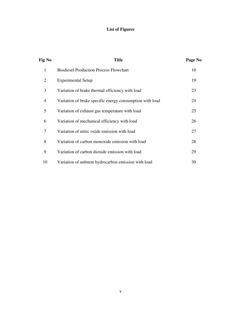
List of Figures
Fig No Title Page No
1 Biodiesel Production Process Flowchart 10
2 Experimental Setup 19
3 Variation of brake thermal efficiency with load 23
4 Variation of brake specific energy consumption with load 24
5 Variation of exhaust gas temperature with load 25
6 Variation of mechanical efficiency with load 26
7 Variation of nitric oxide emission with load 27
8 Variation of carbon monoxide emission with load 28
9 Variation of carbon dioxide emission with load 29
10 Variation of unburnt hydrocarbon emission with load 30
vi
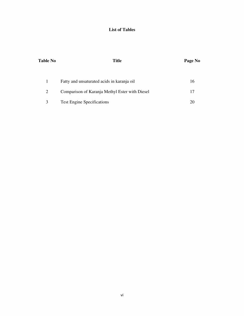
List of Tables
Table No Title Page No
1 Fatty and unsaturated acids in karanja oil 16
2 Comparison of Karanja Methyl Ester with Diesel 17
3 Test Engine Specifications 20
vii
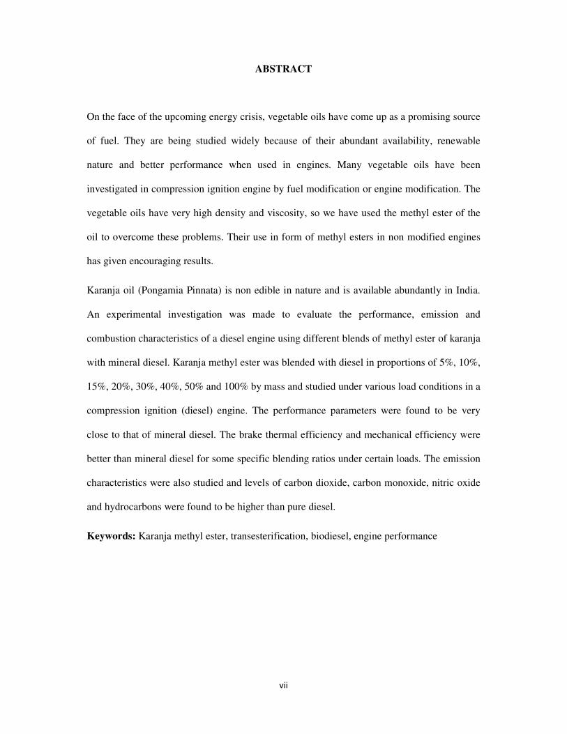
ABSTRACT
On the face of the upcoming energy crisis, vegetable oils have come up as a promising source
of fuel. They are being studied widely because of their abundant availability, renewable
nature and better performance when used in engines. Many vegetable oils have been
investigated in compression ignition engine by fuel modification or engine modification. The
vegetable oils have very high density and viscosity, so we have used the methyl ester of the
oil to overcome these problems. Their use in form of methyl esters in non modified engines
has given encouraging results.
Karanja oil (Pongamia Pinnata) is non edible in nature and is available abundantly in India.
An experimental investigation was made to evaluate the performance, emission and
combustion characteristics of a diesel engine using different blends of methyl ester of karanja
with mineral diesel. Karanja methyl ester was blended with diesel in proportions of 5%, 10%,
15%, 20%, 30%, 40%, 50% and 100% by mass and studied under various load conditions in a
compression ignition (diesel) engine. The performance parameters were found to be very
close to that of mineral diesel. The brake thermal efficiency and mechanical efficiency were
better than mineral diesel for some specific blending ratios under certain loads. The emission
characteristics were also studied and levels of carbon dioxide, carbon monoxide, nitric oxide
and hydrocarbons were found to be higher than pure diesel.
Keywords: Karanja methyl ester, transesterification, biodiesel, engine performance

1
CHAPTER 1
INTRODUCTION
2
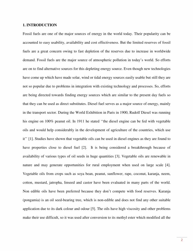
1. INTRODUCTION
Fossil fuels are one of the major sources of energy in the world today. Their popularity can be
accounted to easy usability, availability and cost effectiveness. But the limited reserves of fossil
fuels are a great concern owing to fast depletion of the reserves due to increase in worldwide
demand. Fossil fuels are the major source of atmospheric pollution in today’s world. So efforts
are on to find alternative sources for this depleting energy source. Even though new technologies
have come up which have made solar, wind or tidal energy sources easily usable but still they are
not so popular due to problems in integration with existing technology and processes. So, efforts
are being directed towards finding energy sources which are similar to the present day fuels so
that they can be used as direct substitutes. Diesel fuel serves as a major source of energy, mainly
in the transport sector. During the World Exhibition in Paris in 1900, Rudolf Diesel was running
his engine on 100% peanut oil. In 1911 he stated ‘‘the diesel engine can be fed with vegetable
oils and would help considerably in the development of agriculture of the countries, which use
it’’ [1]. Studies have shown that vegetable oils can be used in diesel engines as they are found to
have properties close to diesel fuel [2]. It is being considered a breakthrough because of
availability of various types of oil seeds in huge quantities [3]. Vegetable oils are renewable in
nature and may generate opportunities for rural employment when used on large scale [4].
Vegetable oils from crops such as soya bean, peanut, sunflower, rape, coconut, karanja, neem,
cotton, mustard, jatropha, linseed and castor have been evaluated in many parts of the world.
Non edible oils have been preferred because they don’t compete with food reserves. Karanja
(pongamia) is an oil seed-bearing tree, which is non-edible and does not find any other suitable
application due to its dark colour and odour [5]. The oils have high viscosity and other problems
make their use difficult, so it was used after conversion to its methyl ester which modified all the

3
characteristics to suit our demand. In this work, different proportions of karanja methyl ester, viz,
5%, 10%, 15%, 20%, 30%, 40% and 50% are mixed with 95%, 90%, 85%, 80%, 70%, 60% and
50% respectively with diesel fuel on mass basis.

4
CHAPTER 2
LITERATURE REVIEW
5
2. LITERATURE REVIEW
2.1 Engines
Engines are devices which convert the stored chemical energy in fuels and chemicals into
mechanical or motive energy. They are basically of two types- external combustion engines and
internal combustion engines. External combustion engines have separate areas where the
chemical reaction or combustion takes place and where motive energy is generated. This class of
engines includes steam engines. Internal combustion engines on other hand handle the
combustion and power generation in the same place. These engines can either be petrol or diesel
engines.
These petrol or diesel engines can run either in a 2 stroke cycle or a 4 stroke cycle. While a 2
stroke engine provides more power per cycle, the efficiency is higher in a 4 stroke engine. A
diesel engine is an internal combustion engine that converts chemical energy in fuel to
mechanical energy that moves pistons up and down inside enclosed spaces called cylinders. The
pistons are connected to the engine’s crankshaft, which changes their linear motion into the
rotary motion needed to propel the vehicle’s wheels. With both gasoline and diesel engines,
energy is released in a series of small explosions (combustion) as fuel reacts chemically with
oxygen from the air. Diesels differ from gasoline engines primarily in the way the explosions
occur. Gasoline engines start the explosions with sparks from spark plugs, whereas in diesel
engines, fuel ignites on its own. Air heats up when it’s compressed. This fact led German
engineer Rudolf Diesel to theorize that fuel could be made to ignite spontaneously if the air
inside an engine’s cylinders became hot enough through compression. Achieving high
temperatures meant producing much greater air compression than occurs in gasoline engines, but
6
Diesel saw that as a plus. According to his calculations, high compression should lead to high
engine efficiency [6]. Part of the reason is that compressing air concentrates fuel-burning
oxygen. A fuel that has high energy content per gallon, like diesel fuel, should be able to react
with most of the concentrated oxygen to deliver more punch per explosion, if it was injected into
an engine’s cylinders at exactly the right time. Diesel’s calculations were correct. As a result,
although diesel engines have seen vast improvements, the basic concept of the four-stroke diesel
engine has remained virtually unchanged for over 100 years. The first stroke involves drawing
air into a cylinder as the piston creates space for it by moving away from the intake valve. The
piston’s subsequent upward swing then compresses the air, heating it at the same time. Next, fuel
is injected under high pressure as the piston approaches the top of its compression stroke,
igniting spontaneously as it contacts the heated air. The hot combustion gases expand, driving
the piston downward in what’s called the power stroke. During its return swing, the piston
pushes spent gases from the cylinder, and the cycle begins again with an intake of fresh air.
Older diesel engines mixed fuel and air in a pre-combustion chamber before injecting it into a
cylinder. The mixing and injection steps were controlled mechanically, which made it very
difficult to tailor the fuel-air mixture to changing engine conditions. This led to incomplete fuel
combustion, particularly at low speeds. As a result, fuel was wasted and tailpipe emissions were
relatively high. Today’s diesels inject fuel directly into an engine’s cylinders using tiny
computers to deliver precisely the right amount of fuel the instant it is needed. All functions in a
modern diesel engine are controlled by an electronic control module that communicates with an
elaborate array of sensors placed at strategic locations throughout the engine to monitor
everything from engine speed to coolant and oil temperatures and even piston position. Tight
7
electronic control means that fuel burns more thoroughly, delivering more power, greater fuel
economy, and fewer emissions than yesterday’s diesel engines could achieve. Diesels are
workhorse engines and can be found powering heavy duty trucks, buses, tractors and trains, large
ships, bulldozers, cranes, and other construction equipment. They are more fuel efficient and
more flexible in the fuels they can use.
Diesel engines are more efficient than gasoline engines (45 percent versus 30 percent), and
further advances are possible (to 55-63 percent). Research is being done by engine manufacturers
and fuel suppliers to develop new fuels of plant origin (biofuels) that can provide optimum
performance in diesel engines in order to fight the decreasing supplies of fossil fuels.
2.2 Need for Oil Treatment/Conversion
Straight vegetable oils (SVO) can be used directly as a fossil diesel substitute; however, using
this fuel can lead to some fairly serious engine problems. Due to its relatively high viscosity
SVO leads to poor atomisation of the fuel, incomplete combustion, coking of the fuel injectors,
ring carbonisation, and accumulation of fuel in the lubricating oil. The best method for solving
these problems is the transesterification of the oil to produce biodiesel.
Biodiesel is an alternative fuel similar to conventional or ‘fossil’ diesel. Biodiesel can be
produced from straight vegetable oil, animal oil/fats, tallow and waste cooking oil. The process
used to convert these oils to Biodiesel is called transesterification. The largest possible source of
suitable oil comes from oil crops such as rapeseed, palm or soybean. In the UK rapeseed
represents the greatest potential for biodiesel production. Most biodiesel produced at present is
produced from waste vegetable oil sourced from restaurants, chip shops, industrial food
producers, etc. Though oil straight from the agricultural industry represents the greatest potential
8
source, it is not being produced commercially simply because the raw oil is too expensive. After
the cost of converting it to biodiesel has been added on it is simply too expensive to compete
with fossil diesel. Waste vegetable oil can often be sourced for free or sourced already treated for
a small price. The result is Biodiesel produced from waste vegetable oil can compete with fossil
diesel.
2.3 Biodiesel Production
As mentioned above biodiesel can be produced from straight vegetable oil, animal oil/fats, tallow
and waste oils. There are three basic routes to biodiesel production from oils and fats:
• Base catalyzed transesterification of the oil.
• Direct acid catalyzed transesterification of the oil.
• Conversion of the oil to its fatty acids and then to biodiesel.
Almost all biodiesel is produced using base catalyzed transesterification as it is the most
economical process requiring only low temperatures and pressures and producing a 98%
conversion yield. For this reason only this process will be described in this report.
The Transesterification process is the reaction of a triglyceride (fat/oil) with an alcohol to form
esters and glycerol. A triglyceride has a glycerine molecule as its base with three long chain fatty
acids attached. The characteristics of the fat are determined by the nature of the fatty acids
attached to the glycerine. The nature of the fatty acids can in turn affect the characteristics of the
biodiesel. During the esterification process, the triglyceride is reacted with alcohol in the
presence of a catalyst, usually a strong alkaline like sodium hydroxide or potassium hydroxide.
9
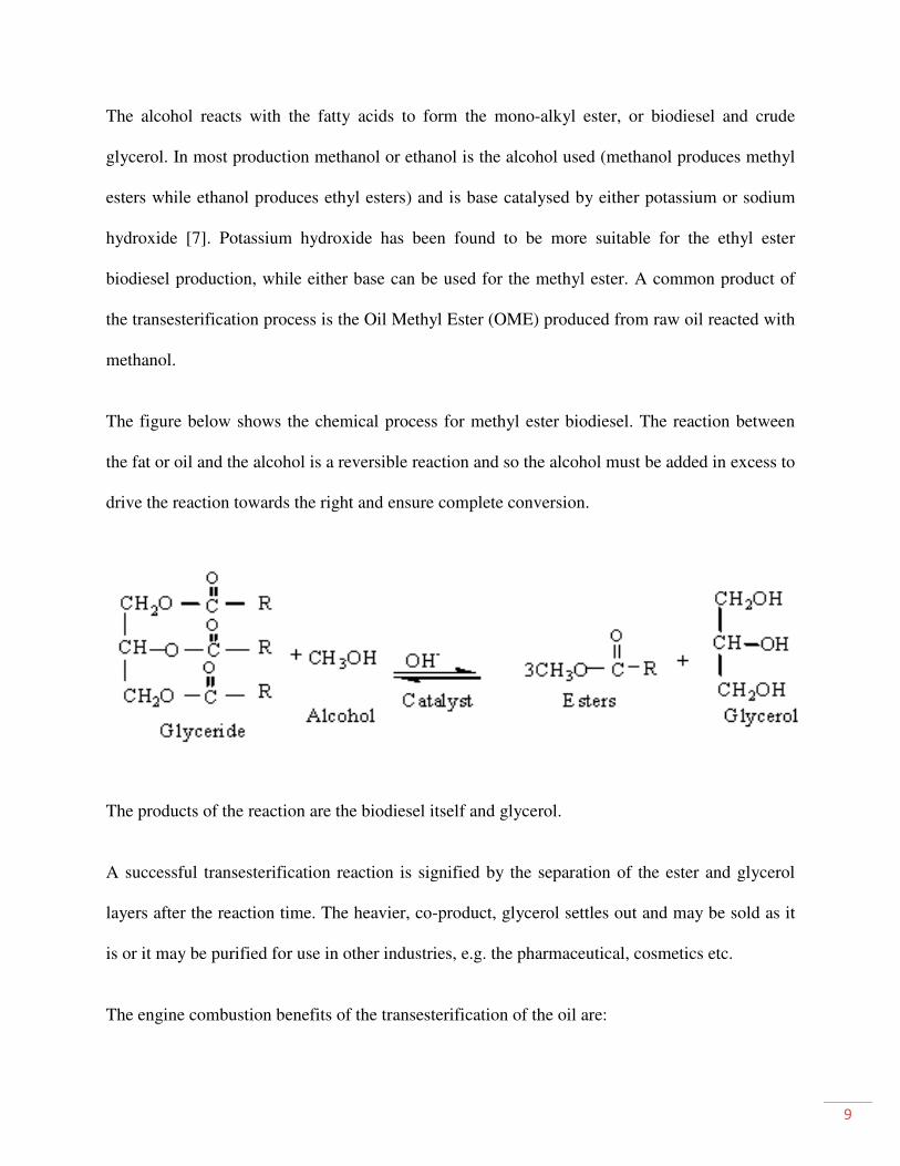
The alcohol reacts with the fatty acids to form the mono-alkyl ester, or biodiesel and crude
glycerol. In most production methanol or ethanol is the alcohol used (methanol produces methyl
esters while ethanol produces ethyl esters) and is base catalysed by either potassium or sodium
hydroxide [7]. Potassium hydroxide has been found to be more suitable for the ethyl ester
biodiesel production, while either base can be used for the methyl ester. A common product of
the transesterification process is the Oil Methyl Ester (OME) produced from raw oil reacted with
methanol.
The figure below shows the chemical process for methyl ester biodiesel. The reaction between
the fat or oil and the alcohol is a reversible reaction and so the alcohol must be added in excess to
drive the reaction towards the right and ensure complete conversion.
The products of the reaction are the biodiesel itself and glycerol.
A successful transesterification reaction is signified by the separation of the ester and glycerol
layers after the reaction time. The heavier, co-product, glycerol settles out and may be sold as it
is or it may be purified for use in other industries, e.g. the pharmaceutical, cosmetics etc.
The engine combustion benefits of the transesterification of the oil are:
10
• Lowered viscosity
• Complete removal of the glycerides
• Lowered boiling point
• Lowered flash point
• Lowered pour point
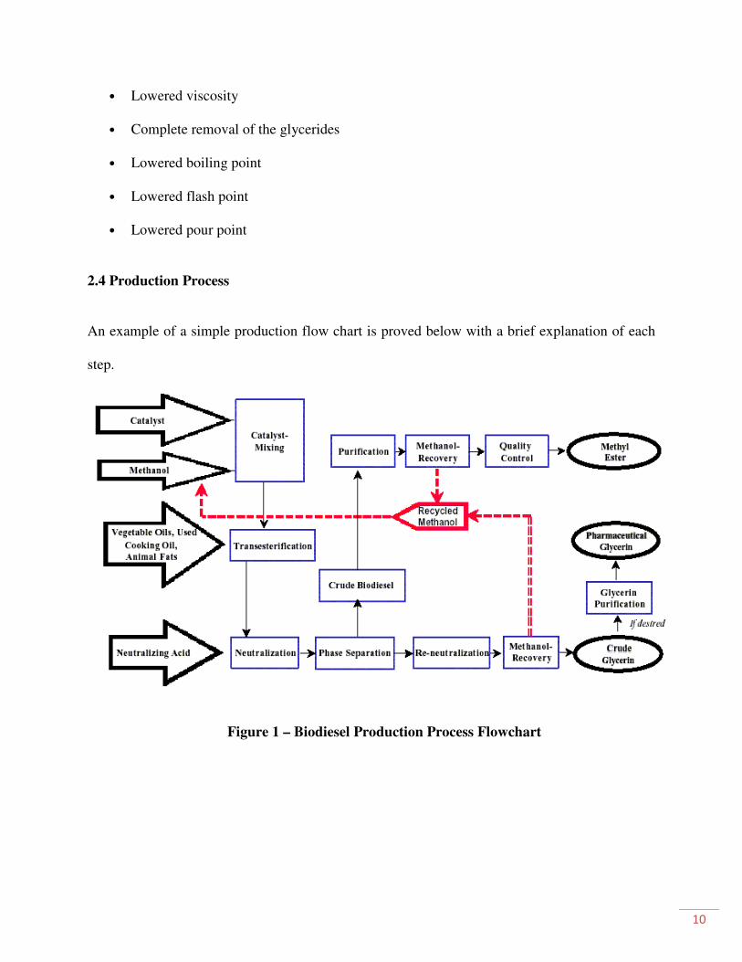
2.4 Production Process
An example of a simple production flow chart is proved below with a brief explanation of each
step.
Figure 1 – Biodiesel Production Process Flowchart
11
2.4.1 Mixing of alcohol and catalyst
The catalyst is typically sodium hydroxide (caustic soda) or potassium hydroxide (potash). It is
dissolved in the alcohol using a standard agitator or mixer. The alcohol/catalyst mix is then
charged into a closed reaction vessel and the oil or fat is added. The system from here on is
totally closed to the atmosphere to prevent the loss of alcohol. The reaction mix is kept just
above the boiling point of the alcohol (around 160 °F) to speed up the reaction and the reaction
takes place. Recommended reaction time varies from 1 to 8 hours, and some systems recommend
the reaction take place at room temperature. Excess alcohol is normally used to ensure total
conversion of the fat or oil to its esters. Care must be taken to monitor the amount of water and
free fatty acids in the incoming oil or fat. If the free fatty acid level or water level is too high it
may cause problems with soap formation and the separation of the glycerine by-product
downstream.
2.4.2 Separation
Once the reaction is complete, two major products are obtained: glycerine and biodiesel. Each
has a substantial amount of the excess alcohol that was used in the reaction. The reacted mixture
is sometimes neutralized at this step if needed. The glycerine is much more dense than biodiesel
and the two can be gravity separated with glycerine simply drawn off the bottom of the settling
vessel. In some cases, a centrifuge is used to separate the two materials faster [8].
2.4.3 Alcohol Removal
Once the glycerine and biodiesel phases have been separated, the excess alcohol in each phase is
removed with a flash evaporation process or by distillation. In others systems, the alcohol is
12
removed and the mixture neutralized before the glycerine and esters have been separated. In
either case, the alcohol is recovered using distillation equipment and is re-used. Care must be
taken to ensure no water accumulates in the recovered alcohol stream.
2.4.4 Glycerine Neutralization
The glycerine by-product contains unused catalyst and soaps that are neutralized with an acid
and sent to storage as crude glycerine. In some cases the salt formed during this phase is
recovered for use as fertilizer. In most cases the salt is left in the glycerine. Water and alcohol are
removed to produce 80-88% pure glycerine that is ready to be sold as crude glycerine. In more
sophisticated operations, the glycerine is distilled to 99% or higher purity and sold into the
cosmetic and pharmaceutical markets.
2.4.5 Methyl Ester Wash
Once separated from the glycerine, the biodiesel is sometimes purified by washing gently with
warm water to remove residual catalyst or soaps, dried, and sent to storage. In some processes
this step is unnecessary. This is normally the end of the production process resulting in a clear
amber-yellow liquid with a viscosity similar to mineral diesel. In some systems the biodiesel is
distilled in an additional step to remove small amounts of colour bodies to produce a colourless
biodiesel.
13
2.4.6 Product Quality
Prior to use as a commercial fuel, the finished biodiesel must be analyzed using sophisticated
analytical equipment to ensure it meets any required specifications. The most important aspects
of biodiesel production to ensure trouble free operation in diesel engines are:
• Complete Reaction
• Removal of Glycerine
• Removal of Catalyst
• Removal of Alcohol
• Absence of Free Fatty Acids

14
CHAPTER 3
MATERIALS & METHODS
15
3. MATERIALS AND METHODS
As the viscosity of karanja oil is higher than that of diesel fuel, it is necessary to use a viscosity
reduction technique to evaluate its performance and emission in a diesel engine. Therefore, it is
required to modify the fuel. So certain approaches are used to modify vegetable oils to better
usable forms. Blending is a simple method of modification in which another liquid with a certain
character is mixed to get the average required parameter. But the problems of separation of the
mixture components and coking occur. So a chemical process called transesterification is
preferred [9]. This process produces uniform quality of the alkyl esters and reduces viscosity and
increases cetane number [10].
Biodiesel can be produced by a variety of esterification technologies. The oils and fats are
filtered and pre-processed to remove water and contaminants. If, free fatty acids are present, they
can be removed or transformed into biodiesel using special pre-treatment technologies. Non-
edible oil like karanja oils having acid values more than 3.0 were esterified followed by
transesterification. Esterification is the reaction of an acid with an alcohol in the presence of a
catalyst to form an ester. Transesterification on the other hand is the displacement of the alcohol
from an ester by another alcohol in a process similar to hydrolysis, except that an alcohol is used
instead of water. This reaction cleavage of an ester by an alcohol is more specifically called
alcoholysis. In case of esterification processes, the karanja oil is preheated at different
temperature and then the solution of sulfuric acid and methanol is added to the oil and stirred
continuously at different temperature. Esterification is continued till the acid value was lowered
and remained constant (between 0.1 and 0.5). Then the heating was stopped and the products
were cooled. The unreacted methanol was separated by distillation. The remaining product was
further used for transesterification to obtain methyl esters. The karanja oil was converted to
16
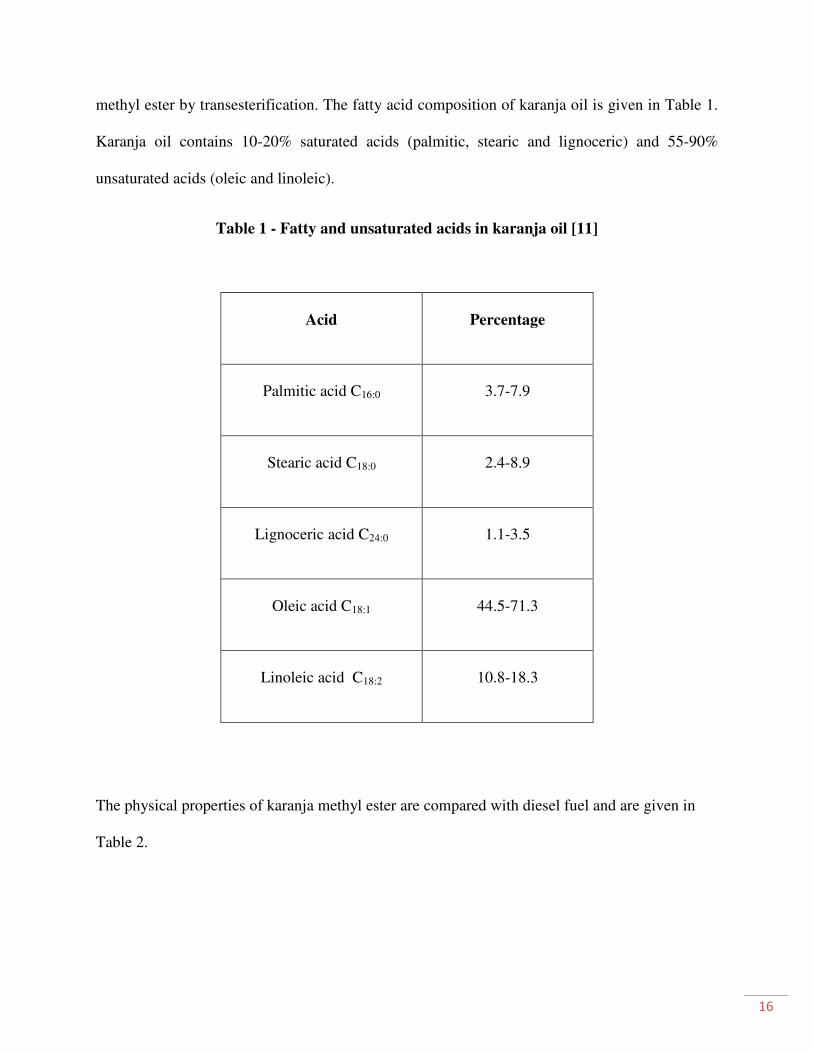
methyl ester by transesterification. The fatty acid composition of karanja oil is given in Table 1.
Karanja oil contains 10-20% saturated acids (palmitic, stearic and lignoceric) and 55-90%
unsaturated acids (oleic and linoleic).
Table 1 - Fatty and unsaturated acids in karanja oil [11]
Acid Percentage
Palmitic acid C16:0 3.7-7.9
Stearic acid C18:0 2.4-8.9
Lignoceric acid C24:0 1.1-3.5
Oleic acid C18:1 44.5-71.3
Linoleic acid C18:2 10.8-18.3
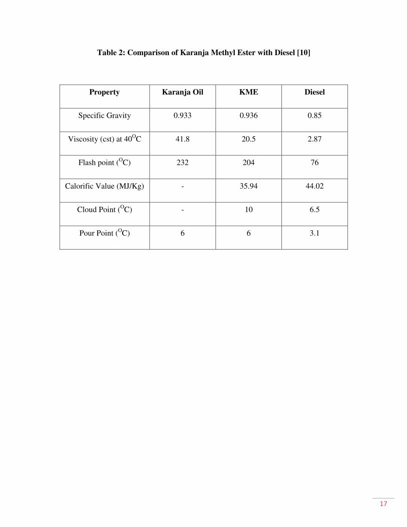
The physical properties of karanja methyl ester are compared with diesel fuel and are given in
Table 2.
17
Table 2: Comparison of Karanja Methyl Ester with Diesel [10]
Property Karanja Oil KME Diesel
Specific Gravity 0.933 0.936 0.85
Viscosity (cst) at 40OC 41.8 20.5 2.87
Flash point (OC) 232 204 76
Calorific Value (MJ/Kg) - 35.94 44.02
Cloud Point (OC) - 10 6.5
Pour Point (OC) 6 6 3.1

18
CHAPTER 4
EXPERIMENTAL SETUP
19
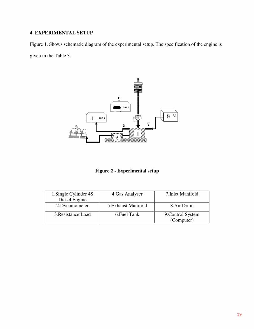
4. EXPERIMENTAL SETUP
Figure 1. Shows schematic diagram of the experimental setup. The specification of the engine is
given in the Table 3.
Figure 2 - Experimental setup
1.Single Cylinder 4S
Diesel Engine
4.Gas Analyser 7.Inlet Manifold
2.Dynamometer 5.Exhaust Manifold 8.Air Drum
3.Resistance Load 6.Fuel Tank 9.Control System
(Computer)
20
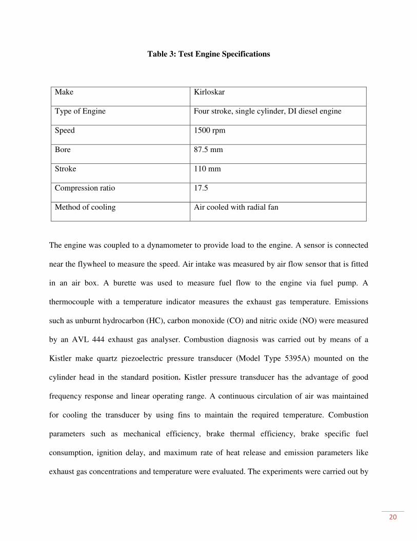
Table 3: Test Engine Specifications
Make Kirloskar
Type of Engine Four stroke, single cylinder, DI diesel engine
Speed 1500 rpm
Bore 87.5 mm
Stroke 110 mm
Compression ratio 17.5
Method of cooling Air cooled with radial fan
The engine was coupled to a dynamometer to provide load to the engine. A sensor is connected
near the flywheel to measure the speed. Air intake was measured by air flow sensor that is fitted
in an air box. A burette was used to measure fuel flow to the engine via fuel pump. A
thermocouple with a temperature indicator measures the exhaust gas temperature. Emissions
such as unburnt hydrocarbon (HC), carbon monoxide (CO) and nitric oxide (NO) were measured
by an AVL 444 exhaust gas analyser. Combustion diagnosis was carried out by means of a
Kistler make quartz piezoelectric pressure transducer (Model Type 5395A) mounted on the
cylinder head in the standard position. Kistler pressure transducer has the advantage of good
frequency response and linear operating range. A continuous circulation of air was maintained
for cooling the transducer by using fins to maintain the required temperature. Combustion
parameters such as mechanical efficiency, brake thermal efficiency, brake specific fuel
consumption, ignition delay, and maximum rate of heat release and emission parameters like
exhaust gas concentrations and temperature were evaluated. The experiments were carried out by

21
using various blends of karanja methyl ester (KME5,10,15,20,30,40,50,100) with diesel at
different load conditions on the engine keeping all the independent variables same. The engine
performance test was done twice for all blends except the KME100 and average was taken and
emission readings were taken thrice and average was taken.

22
CHAPTER 5
RESULTS & DISCUSSION

23
5. RESULTS & DISCUSSION
5.1 Performance Parameters
5.1.1 Brake Thermal Efficiency (BTE)
Figure 3 – Variation of brake thermal efficiency with load
Figure 3 shows the variation of the brake thermal efficiency with respect to load for diesel
fuel and karanja methyl ester-diesel fuel blends. It can be observed from the figure that,
KME100 shows higher brake thermal efficiencies at all load conditions compared to that of
diesel fuel. Almost all blends show slightly better BTE than diesel at higher load conditions.
The higher thermal efficiencies may be due to the additional lubricity provided by the fuel
blends [12]. Raheman et al. [13] also report higher BTE for the 20% & 40% blends while the
0
5
10
15
20
25
30
35
0 0.5 1 1.5 2 2.5 3 3.5 4 4.5
Bra
ke
Th
erm
al
Eff
icie
ncy
(%
)
Load (KW)
Diesel
KVO5
KVO10
KVO15
KVO20
KVO30
KVO40
KVO50
KVO100
24
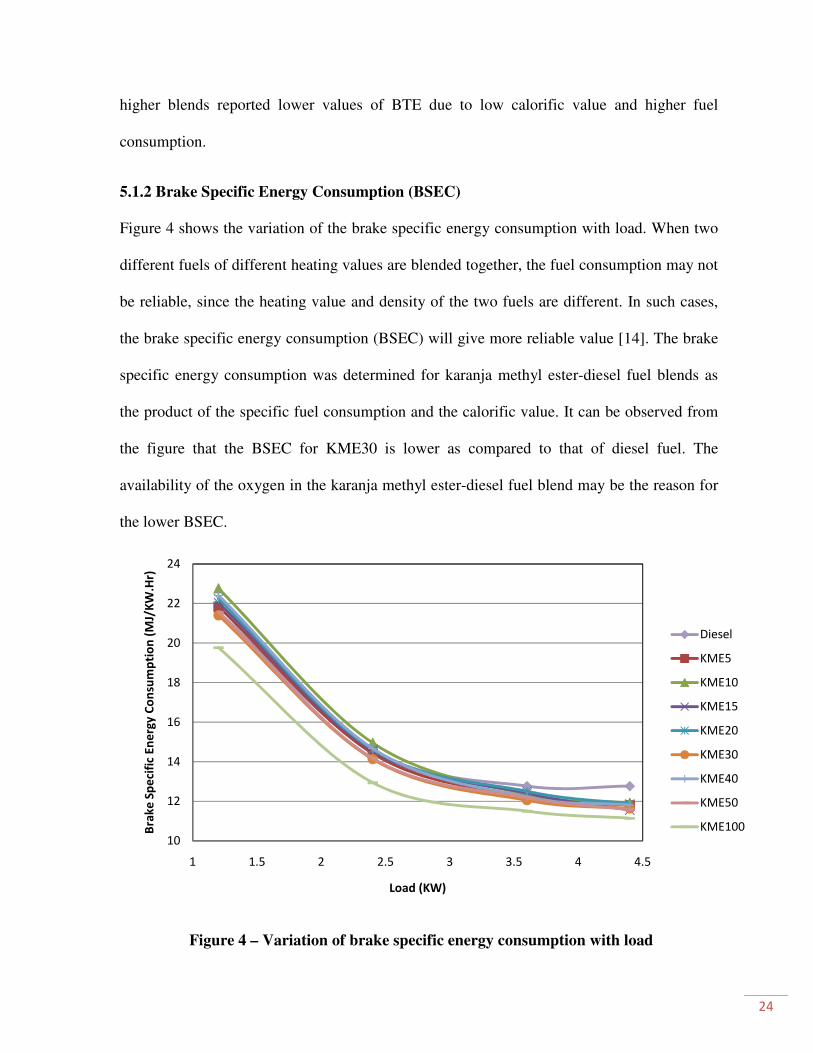
higher blends reported lower values of BTE due to low calorific value and higher fuel
consumption.
5.1.2 Brake Specific Energy Consumption (BSEC)
Figure 4 shows the variation of the brake specific energy consumption with load. When two
different fuels of different heating values are blended together, the fuel consumption may not
be reliable, since the heating value and density of the two fuels are different. In such cases,
the brake specific energy consumption (BSEC) will give more reliable value [14]. The brake
specific energy consumption was determined for karanja methyl ester-diesel fuel blends as
the product of the specific fuel consumption and the calorific value. It can be observed from
the figure that the BSEC for KME30 is lower as compared to that of diesel fuel. The
availability of the oxygen in the karanja methyl ester-diesel fuel blend may be the reason for
the lower BSEC.
Figure 4 – Variation of brake specific energy consumption with load
10
12
14
16
18
20
22
24
1 1.5 2 2.5 3 3.5 4 4.5
Bra
ke
Sp
eci
fic
En
erg
y C
on
sum
pti
on
(M
J/K
W.H
r)
Load (KW)
Diesel
KME5
KME10
KME15
KME20
KME30
KME40
KME50
KME100
25
In the case of lower load conditions, the incomplete mixture of high viscosity KME may
lead to incomplete combustion and require additional fuel air mixture to produce the same
power output as that of diesel fuel.
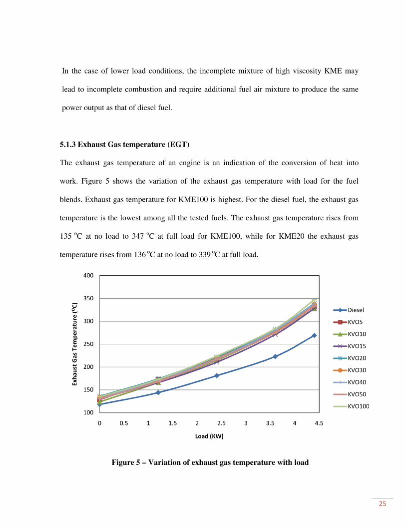
5.1.3 Exhaust Gas temperature (EGT)
The exhaust gas temperature of an engine is an indication of the conversion of heat into
work. Figure 5 shows the variation of the exhaust gas temperature with load for the fuel
blends. Exhaust gas temperature for KME100 is highest. For the diesel fuel, the exhaust gas
temperature is the lowest among all the tested fuels. The exhaust gas temperature rises from
135 o
C at no load to 347 o
C at full load for KME100, while for KME20 the exhaust gas
temperature rises from 136 o
C at no load to 339 o
C at full load.
Figure 5 – Variation of exhaust gas temperature with load
100
150
200
250
300
350
400
0 0.5 1 1.5 2 2.5 3 3.5 4 4.5
Ex
ha
ust
Ga
s T
em
pe
ratu
re (
OC
)
Load (KW)
Diesel
KVO5
KVO10
KVO15
KVO20
KVO30
KVO40
KVO50
KVO100
26
In the case of karanja methyl ester-diesel fuel blends, the heat release may occur in the later
part of the power stroke. So this may result in lower time for heat dissipation and higher
exhaust gas temperatures. Result of studies on bio oil blends by Prakash et al. [15] agrees
with our results.
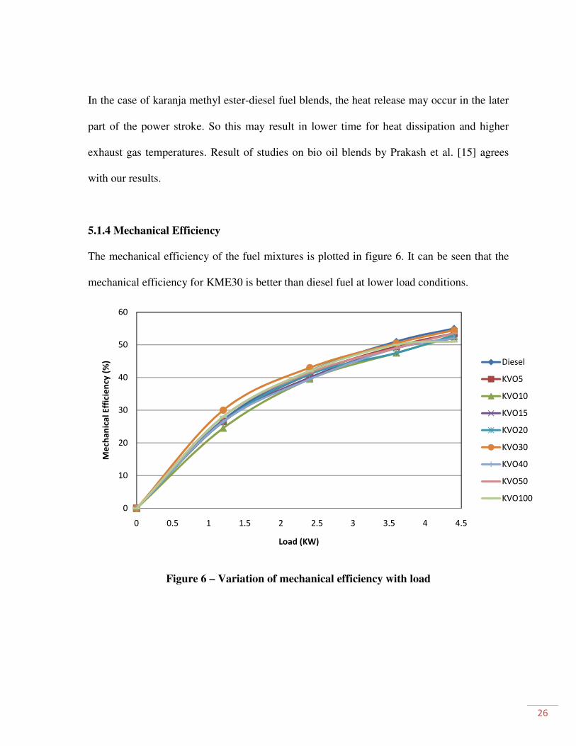
5.1.4 Mechanical Efficiency
The mechanical efficiency of the fuel mixtures is plotted in figure 6. It can be seen that the
mechanical efficiency for KME30 is better than diesel fuel at lower load conditions.
Figure 6 – Variation of mechanical efficiency with load
0
10
20
30
40
50
60
0 0.5 1 1.5 2 2.5 3 3.5 4 4.5
Me
cha
nic
al
Eff
icie
ncy
(%
)
Load (KW)
Diesel
KVO5
KVO10
KVO15
KVO20
KVO30
KVO40
KVO50
KVO100
27
5.2 Emission Parameters
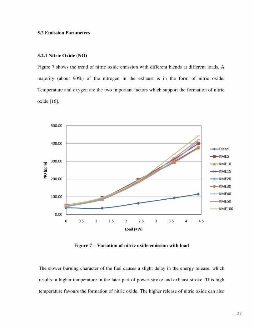
5.2.1 Nitric Oxide (NO)
Figure 7 shows the trend of nitric oxide emission with different blends at different loads. A
majority (about 90%) of the nitrogen in the exhaust is in the form of nitric oxide.
Temperature and oxygen are the two important factors which support the formation of nitric
oxide [16].
Figure 7 – Variation of nitric oxide emission with load
The slower burning character of the fuel causes a slight delay in the energy release, which
results in higher temperature in the later part of power stroke and exhaust stroke. This high
temperature favours the formation of nitric oxide. The higher release of nitric oxide can also
0.00
100.00
200.00
300.00
400.00
500.00
0 0.5 1 1.5 2 2.5 3 3.5 4 4.5
NO
(p
pm
)
Load (KW)
Diesel
KME5
KME10
KME15
KME20
KME30
KME40
KME50
KME100
28
be attributed to presence of nitrogenous compounds in the fuels of plant origin. At higher
loads, more fuel is burnt and higher temperature of the exhaust gases results in higher
production of nitric oxide. Nabi et al. [17] also reported higher NOx with karanja biodiesel.
Banapurmatha et al. [18] reported that nitric oxide emission was reduced with changing of
injection timing for certain biodiesels.
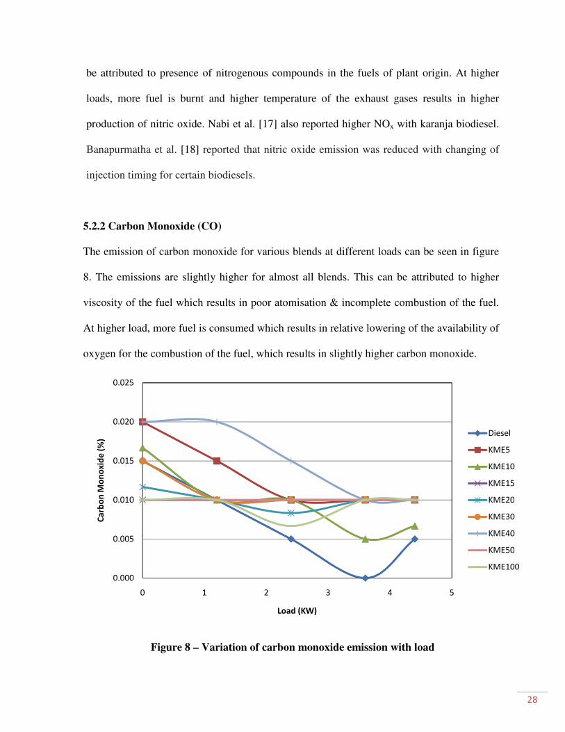
5.2.2 Carbon Monoxide (CO)
The emission of carbon monoxide for various blends at different loads can be seen in figure
8. The emissions are slightly higher for almost all blends. This can be attributed to higher
viscosity of the fuel which results in poor atomisation & incomplete combustion of the fuel.
At higher load, more fuel is consumed which results in relative lowering of the availability of
oxygen for the combustion of the fuel, which results in slightly higher carbon monoxide.
Figure 8 – Variation of carbon monoxide emission with load
0.000
0.005
0.010
0.015
0.020
0.025
0 1 2 3 4 5
Ca
rbo
n M
on
ox
ide
(%
)
Load (KW)
Diesel
KME5
KME10
KME15
KME20
KME30
KME40
KME50
KME100
29
Prakash et al. [15] report a slight increase in CO emission in engine testing with wood
pyrolysis oil blends.
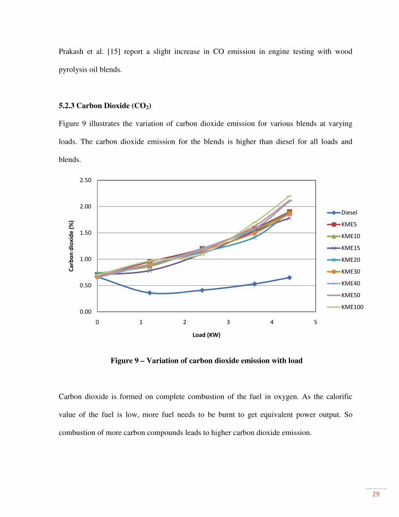
5.2.3 Carbon Dioxide (CO2)
Figure 9 illustrates the variation of carbon dioxide emission for various blends at varying
loads. The carbon dioxide emission for the blends is higher than diesel for all loads and
blends.
Figure 9 – Variation of carbon dioxide emission with load
Carbon dioxide is formed on complete combustion of the fuel in oxygen. As the calorific
value of the fuel is low, more fuel needs to be burnt to get equivalent power output. So
combustion of more carbon compounds leads to higher carbon dioxide emission.
0.00
0.50
1.00
1.50
2.00
2.50
0 1 2 3 4 5
Ca
rbo
n d
iox
ide
(%
)
Load (KW)
Diesel
KME5
KME10
KME15
KME20
KME30
KME40
KME50
KME100
30
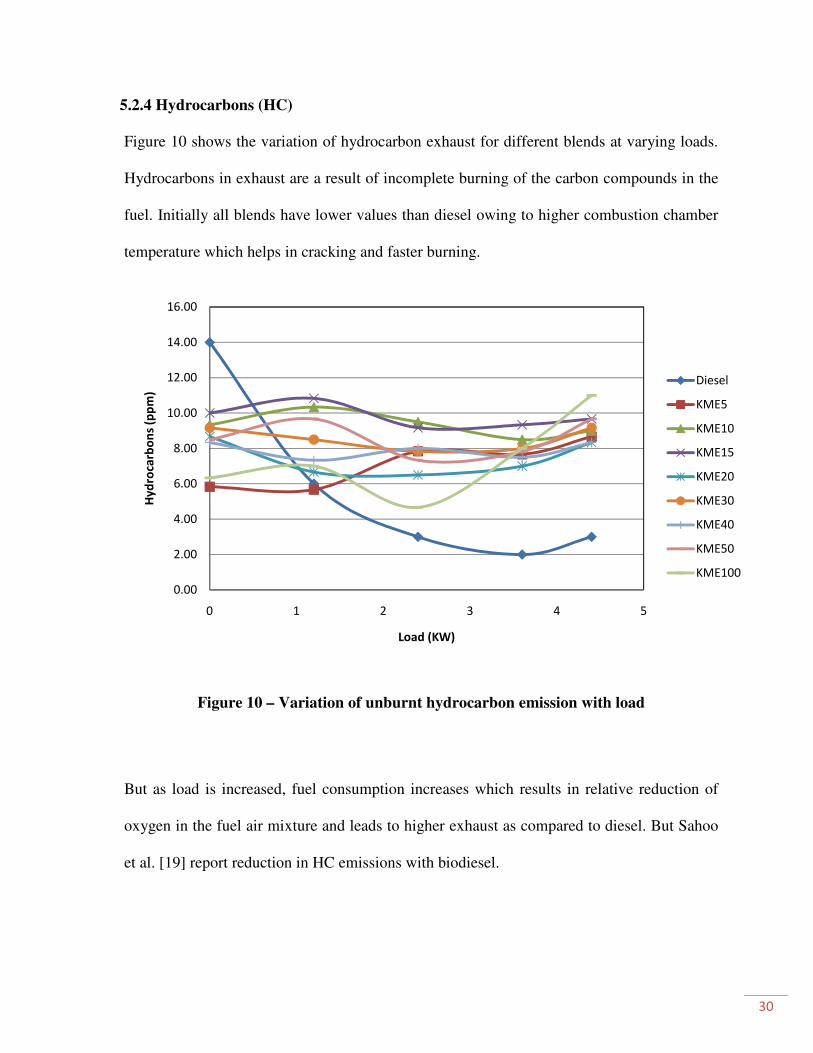
5.2.4 Hydrocarbons (HC)
Figure 10 shows the variation of hydrocarbon exhaust for different blends at varying loads.
Hydrocarbons in exhaust are a result of incomplete burning of the carbon compounds in the
fuel. Initially all blends have lower values than diesel owing to higher combustion chamber
temperature which helps in cracking and faster burning.
Figure 10 – Variation of unburnt hydrocarbon emission with load
But as load is increased, fuel consumption increases which results in relative reduction of
oxygen in the fuel air mixture and leads to higher exhaust as compared to diesel. But Sahoo
et al. [19] report reduction in HC emissions with biodiesel.
0.00
2.00
4.00
6.00
8.00
10.00
12.00
14.00
16.00
0 1 2 3 4 5
Hy
dro
carb
on
s (p
pm
)
Load (KW)
Diesel
KME5
KME10
KME15
KME20
KME30
KME40
KME50
KME100

31
CHAPTER 6
CONCLUSIONS
32
6. CONCLUSIONS
Karanja methyl ester seems to have a potential to use as alternative fuel in diesel engines.
Blending with diesel decreases the viscosity considerably. The following results are made
from the experimental study-
• The brake thermal efficiency of the engine with karanja methyl ester-diesel blend was
marginally better than with neat diesel fuel.
• Brake specific energy consumption is lower for karanja methyl ester-diesel blends
than diesel at all loading.
• The exhaust gas temperature is found to increase with concentration of karanja
methyl ester in the fuel blend due to coarse fuel spray formation and delayed
combustion.
• The mechanical efficiency achieved with KME30 is higher than diesel at lower
loading conditions. At higher loads, the mechanical efficiency of certain blends is
almost equal to that of diesel.
• The emission characteristics are higher than pure diesel but the KME30 has relatively
better performance with respect to other blends.
• KME30 can be accepted as a suitable fuel for use in standard diesel engines and
further studies can be done with certain additives to improve the emission
characteristics.
33
REFERENCES
[1] Hall D. Put a sunflower in your tank. NEW SCI 1981 (26 Feb): pp. 524-526.
[2] Vijaya Raju N, Amba Prasad Rao G and Ramamohan P, Esterified Jatropha oil as a fuel in
diesel engines, J. Combustin (2000): pp. 65-74.
[3] Agarwal Avinash Kumar, Biofuels (alcohols and biodiesel) applications as fuels for internal
combustion engines, Progress in Energy and Combustion Science 33 (2007): pp. 233–271.
[4] Hamasaki. K, Tajima. H, Takasaki.K, Satohira.K, Enomoto.M, Egawa.H, Utilization of waste
vegetable oil methyl ester for diesel fuel, SAE paper no.2001-01-2021: pp. 1499-1504.
[5] Kesari Vigya, Das Archana, Rangan Latha, Physico-chemical characterization and
antimicrobial activity from seed oil of Pongamia pinnata, a potential biofuel crop, Biomass and
Bioenergy 34 (2010): pp. 108–115.
[6] http://www1.eere.energy.gov/vehiclesandfuels/pdfs/basics/jtb_diesel_engine.pdf
[7] http://en.wikipedia.org/wiki/Biodiesel_production
[8] http://www.esru.strath.ac.uk/EandE/Web_sites/02-03/biofuels/what_biodiesel.htm
[9] Sahoo P.K, Das L.M., Combustion analysis of Jatropha, Karanja and Polanga based biodiesel
as fuel in a diesel engine, Fuel 88 (2009): pp. 994–999.
[10] Singh RK, Preparation of karanja oil methyl ester published in Offshore World, April–May
2006.
[11] Srivastava A, Prasad R., Triglycerides-based diesel fuels, Renew Sustain Energy Rev, 4
(2000): pp. 111–33.
[12] Ganesan. V, Internal combustion engine, TMH publications, 2008, ISBN 10:0-07-064817-4.
34
[13] Raheman H., Phadatare A.G., Diesel engine emissions and performance from blends of
karanja methyl ester and diesel, Biomass and Bioenergy 27 (2004): pp. 393-397
[14] Bajpai S, Das L.M., Feasibility of utilization of Fatty Acid Ethyl Esters-Diesel blends as an
act to fatty acid methyl esters-Diesel blend, Proceedings of the 7th
International Conference of
Biofuels organized by Winrock international (2010): pp. 91-100.
[15] Prakash R., Singh R.K., Murugan S., Performance and Emission Studies in a Diesel Engine
Using Bio Oil-Diesel Blends, Second International Conference on Environmental Science &
Technology (ICEST-2011), Feb 26-28, 2011, Singapore.
[16] Mukunda H.S., “Understanding Combustion”, Universities Press (India) Private Limited
Publication, ISBN 978 81 7371 685 0, P
[17] Nabi Md. N., Hoque S.M.N., Akhter Md.S. Karanja (Pongamia Pinnata) biodiesel
production in Bangladesh, Characterisation of karanja biodiesel & its effect on diesel emissions.
Fuel Processing Technology 90 (2009): pp. 1080–1086
[18] Banapurmatha N.R., Tewaria P.G., Hosmathb R.S., Experimental investigations of a four-
stroke single cylinder direct injection diesel engine operated on dual fuel mode with producer gas
as inducted fuel and honge oil and its methyl ester (HOME) as injected fuels, Renewable Energy
33 (2008): pp. 2007–2018.
[19] Sahoo P.K., Das L.M., Babu M.K.G., Arora P., Singh V.P., Kumar N.R., Varyani T.S.,
Comparative evaluation of performance and emission characteristics of jatropha, karanja and
polanga based biodiesel as fuel in a tractor engine, Fuel 88 (2009): pp. 1698–1707

35
Paper Published:
1. Saswat Rath, Sachin Kumar and R. K. Singh, “Performance and Emission Analysis of
Blends of Karanja Methyl Ester in a Compression Ignition Engine” communicated to
Applied Energy, Elsevier Publication.