Embed Size (px)
Citation preview
.
Performance Analysis of FDDI
Marjory J . Jo h nso n
-4pri1, 1988
Research Ins t i tu te for Advanced Computer Science XASA hn les Research Center
RIACS T R 88.11
IhASA-CB-183206) E E C F C B H b h C E AIALYSIS CP N88-3C3; 1 E L C I ( L A S A ) 20 F C S C L G4d
U I l C l d S G3/61 01b1501
Research Institute for Advanced Computer Science
Performance Analysis of FDDI
Marjora, J. Johnson
April, 1988
Research Institute for Advanced Computer Science NASA Amps Ilesezrch Cezter
The Fiber Distributed Data Interface (FDDI) is an emerging ANSI and I S 0 standard for a 100 megabit-per-second fiber-optic token ring. The purpose of this paper is to analyze performance of the FDDI media-access-control protocol using a simulation developed at NASA Ames Research Center. This study in- cludes both analyses using standard measures of performance (including aver- age delay for asynchronous traffic, channel utilization, and transmission-queue length) and analyses of characteristics of ring behavior which can be attributed to constraints imposed by the timed-token protocol on token-holding time (in- cluding bounded token-rotation time, support for synchronous traffic, and fair- ness of channel access for nodes transmitting asynchronous traffic).
This work was supported by the National Aeronautics and Space Administration under NASA Contract NCC2-387 to the Universities Space Research Association (USRA).
PERFORMANCE ANALYSIS OF FDDI
Marjory J . Johnson Research Institute for Advanced Computer Science
NASA Ames Research Center Moffett Field, California 94095
1. Introduction
-. l h e Fiber Distributed Data interface (FDDij is an emerging American
National Standards Institute (ANSI) and International Standards Organization
( E O ) standard for a 100 megabit-per-second fiber-optic token ring. Performance
capabilities of FDDI far exceed those of the IEEE 802.X set of network proto-
cols, thus creating new and exciting possibilities for future networking. NASA
has several potential uses for FDDI, including the Data Management System on
board the Space Station.
The purpose of this paper is to analyze performance of the FDDI media-
access-control protocol. The results contained herein were obtained by using a
simulator developed at NASA Ames Research Center as a tool for Space Station
developers.* Our analysis consists of two parts. First we analyze FDDI in terms
of standard performance measures, including delay, channel utilization, and
transmission-queue length. Then we analyze characteristics of ring behavior that
stem from constraints imposed by the timed-token protocol on token-holding
time.
*This simulator, called LANES (Local Area Network Simulator), is a parameter-driven simulator of the FDDI media-access-control protocol. LANES was developed by the Data Networks Concepts group at NASA Ames Research Center, under the direction of Terry Grant.
- 2 -
Several performance studies of FDDI have been reported in the literature.
Ulm (91 was the first to analyze performance of the timed-token protocol. He
examined utilization as a function of various ring parameters. Papers by Sevcik
and Johnson (81, by Johnson [4,5,6], and by Dykeman and Bux [2] are primarily
analytical studies of properties of timed-token behavior. A simulation study by
Dykeman and Bux [ 11 focuses on performance characteristics of individual asyn-
chronous priority classes.
2. FDDI Access Protocol
FDDI is a timed-token-rotation protocol; timers within each node coopera-
tively attempt to maintain a specified token-rotation time by using the observed
network load to regulate the amount of time that an individual node may
transmit. Consequently, token-rotation time for FDDI is bounded. This bound
is a function of a ring parameter, called T - Opr, which specifies the expected
token-rotation time. Because token-rotation time is bounded, FDDI is able to
support applications that have stringent requirements on frequency of channel
access, such as packet voice and real-time control. FDDI offers two classes of
service: synchronous service for applications with stringent channel-access
requirements such as those designated above, and asynchronous service for appli-
cations which do not have such stringent channel-access requirements.
Although the protocol supports multiple priorities for asynchronous traffic, in
the analysis reported herein we assume that all asynchronous traffic has the
same priority.
For a detailed discussion of the way the FDDI timers work to control access
to the channel, see [3,5,7]. Synchronous service is discussed in detail in Section
3.2.2.
3. Simulation Results
Parameter Number of Nodes
3.1. Standard Measures of Performance
Value 20
The ring configuration used to obtain the results in this section is presented
in Table 1. The network is homogeneous; all traffic is asynchronous and each
node generates frames at the same specified mean arrival rate. Interarrival times
for frames at each node are exponentially distributed.
Distance between Nodes T Opt Frame Size Header Size
3.1.1. Average Frame Delay
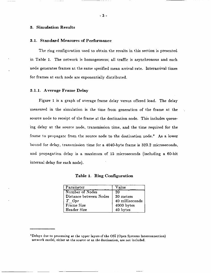
Figure 1 is a graph of average frame delay versus offered load. The delay
measured in the simulation is the time from generation of the frame at the
source node to receipt of the frame at the destination node. This includes queue-
ing delay at the source node, transmission time, and the time required for the
frame to propagate from the source node to the destination node.* As a lower
bound for delay, t,ransmission time for a 4040-byte frame is 323.2 microseconds,
and propagation delay is a maximum of 15 microseconds (including a 60-bit
30 meters 40 milliseconds 4000 bytes 40 bvtes
internal delay for each node).
Table 1. Ring Configuration
*Delays due to processing at the upper layers of the OS1 (Open Systems Interconnection) network model, either at the source or at the destination, are not included.
- 4 -
4000 45001 3500.
3000.
2500.
2000.
1500.
1000.
500.
04 , l , l , l , , , , , l , , , l , l . l , ~ 0 10 20 30 40 50 60 70 80 90 100 110
Offered Load (% of Capacity)
Figure 1. Average Frame Delay vs. Offered Load
Average frame delay increases slowly as a function of offered load. The
slope of the curve doesn't increase rapidly until the offered load exceeds 85% of
capacity. Even when the offered load is 98% of capacity, the average delay is
approximately fifteen frame-transmission times. Maximum frame delays experi-
enced in these runs range from 540.6 microseconds at 5% offered load to 21647.5
microseconds (approximately half the T - Opt value) at 98% offered load.
3.1.2. Channel Utilization
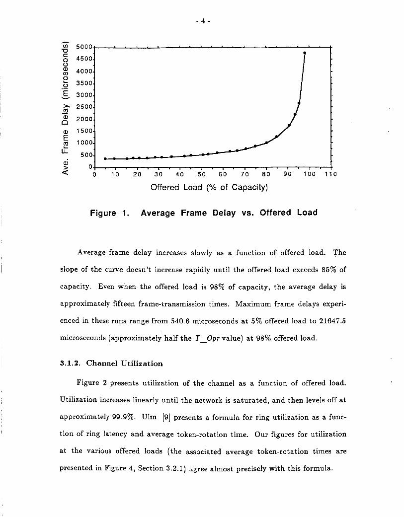
Figure 2 presents utilization of the channel as a function of offered load.
Utilization increases linearly until the network is saturated, and then levels off at
approximately 99.9%. Ulm [9] presents a formula for ring utilization as a func-
tion of ring latency and average token-rotation time. Our figures for utilization
at the various offered loads (the associated average token-rotation times are
presented in Figure 4, Section 3.2.1) crgree almost precisely with this formula.
- 5 -
c 0
Offered Load (“A of Capacity)
Figure 2. Utilization vs. Offered Load
3.1.3. Queue Lengths
At each node frames are placed into the transmission queue as soon as they
are generated, and they remain there until they are transmitted on the channel.
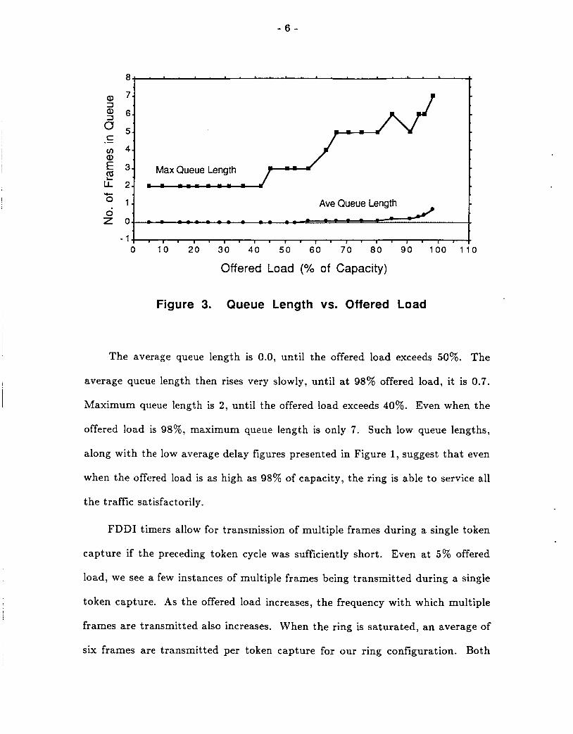
Figure 3 plots both average and maximum queue lengths, as functions of the
offered load. Since our network configuration is homogeneous, for any given
offered load, the average number of frames in the transmission queues at the
individual nodes are all approximately the same. Hence, a single value is given
in Figure 3, rather than presenting a value for each node. The maximum value
given is the maximum over all the nodes.
- 6 -
1.
8 t
Ave Queue Length
0-+ - 5 2
cc 0
0 z
Offered Load (% of Capacity)
Figure 3. Queue Length vs. Offered Load
The average queue length is 0.0, until the offered load exceeds 50%. The
average queue length then rises very slowly, until a t 98% offered load, it is 0.7.
Maximum queue length is 2, until the offered load exceeds 40%. Even when the
offered load is 98%, maximum queue length is only 7. Such low queue lengths,
along with the low average delay figures presented in Figure 1, suggest that even
when the offered load is as high as 98% of capacity, the ring is able to service all
the traffic satisfactorily.
FDDI timers allow for transmission of multiple frames during a single token
capture if the preceding token cycle was sufficiently short. Even at 5% offered
load, we see a few instances of multiple frames being transmitted during a single
token capture. As the offered load increases, the frequency with which multiple
frames are transmitted also increases. When the ring is saturated, an average of
six frames are transmitted per token capture for our ring configuration. Both
- 7 -
Figure 3 and the above information suggest that performance would be degraded
if multiple frames could not be queued for transmission.
3.2. Distinctive Features of Timed-Token Ring Behavior
Distinctive features of ring behavior that stem from constraints of the
timed-token protocol on the time that individual nodes can hold the token
include a bounded token-rotation time, the ability to provide support for syn-
chronous applications, and the ability to provide equal access to individual nodes
for asynchronous transmission. In this section we present simulation data to
support earlier analytic results [4,5,6,8].
3.2.1. Bounded Token-Rotation Time
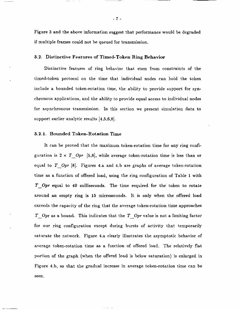
It can be proved that the maximum token-rotation time for any ring confi-
guration is 2 x T - Opr [5,8], while average token-rotation time is less than or
equal to T - Opr [8]. Figures 4.a and 4.b are graphs of average token-rotation
time as a function of offered load, using the ring configuration of Table 1 with
T - Opr equal to 40 milliseconds. The time required for the' token to rotate
around an empty ring is 15 microseconds. It is only when the offered load
exceeds the capacity of the ring that the average token-rotation time approaches
T - Opr as a bound. This indicates that the T - Opr value is not a limiting factor
for our ring configuration except during bursts of activity that temporarily
saturate the network. Figure 4.a clearly illustrates the asymptotic behavior of
average token-rotation time as a function of offered load. The relatively flat
portion of the graph (when the offered load is below saturation) is enlarged in
Figure 4.b, so that the gradual increase in average token-rotation time can be
seen.
- 8 -
40000-L .
35000.
30000.
25000.
20000.
15000.
10000.
5000-
0. -. -5000- I . I I ' I I . I I ' I
L
L
350.
300.
250.
200.
150.
100.
5 0.
0..
Offered Load ("/. of Capacity)
4 0 0 ~ * . . * . c . * . n . , . , . , . I .
- - a
: I , - - - - - - -
l ' l . l . l , , , 1 . t
Fig. 4.a. Complete graph, skozoing nsympfofic behavior
Fig. 4.b. Enlargement of boffom portion of Fig. 4.a
Figure 4. Average Token-Rotation Time vs. Offered Load
1 -
- 9 -
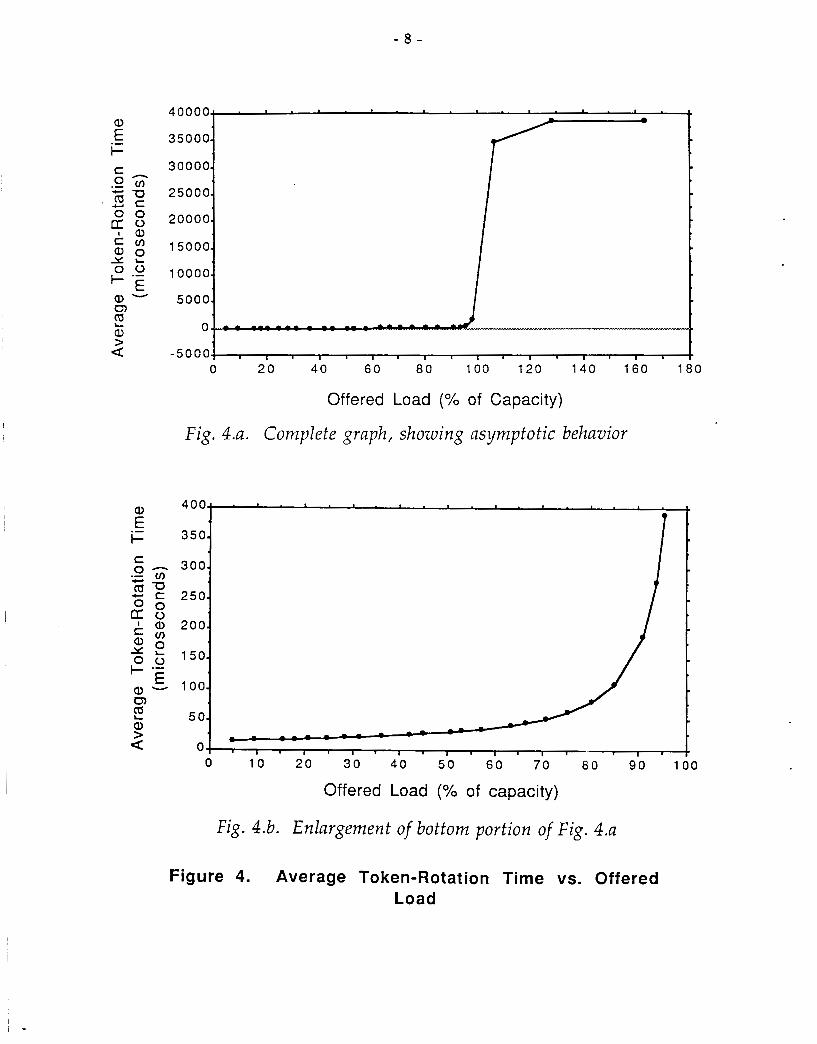
Related information that sheds light on the responsiveness of FDDI is the
amount of time a node must wait to be serviced when it has one or more frames
queued for transmission. Table 2 presents both average and maximum values
for a range of offered loads.
3.2.2. Synchronous Service
The FDDI media-access-control (MAC) protocol guarantees a bounded ser-
vice interval for synchronous applications. That is, at any given time during
ring operation, a node which has been assigned some synchronous bandwidth is
guaranteed to be serviced within a specified time interval, which we call the
synchronous-access time interval. This guarantee is possible only because token-
rotation time is bounded. At ring initialization, nodes negotiate the value of
T - Opr, a ring parameter which specifies the expected token-rotation time, so
that synchronous channel-access requirements of all the nodes will be satisfied.
The smallest requested value is assigned to T Opr. Then each node is assigned -
Table 2. Wait for Usable Token
Offered Load [% of capacity)
10 20 30 40 50 60 70 80
* 90 95 105
Average Wait (microseconds)
30 47 76
133 151 309 421 650
1367 2348
30246
Maximum Wait [microseconds)
509 968
1328 1913 2189 5723 4800 6097 9469
13244 38493
- 10-
an amount of time, called its synchronous-bandzoidth allocation, for synchronous
transmission each time it receives the token. Each time a node receives the
token, it may transmit synchronous frames for its allotted time. In contrast,
asynchronous transmission is allowed only if the load on the ring is light enough
to support it.
The total of all synchronous assignments must not exceed 100 percent of
T Opr, since this is total capacity of the ring. Hence, the value of T Opr
determines the maximum possible volume of synchronous traffic that can be sup-
ported in a particular ring configuration. For this reason, it is worthwhile to
determine the largest possible value of T - Opr that will provide satisfactory
channel access to support the network’s synchronous traffic. An additional rea-
son for assigning the largest possible value to T Opr is that ring operation will
be more efficient, although this factor was negligible in experiments conducted
for this study. Since the average token-rotation time approaches T Opr as the
offered load nears capacity, clearly T - O p r must be assigned a value less than or
equal to the length of the synchronous-access time interval, or synchronous-
frame delay could 5e excessive on a regular basis.
- -
-
-
Since the interval between successive token visits to a node is bounded
above by 2 x T - Opr [5 ,8 ] , the standards document [3] states that T - Opr
should be set to one-half the desired synchronous-access time interval. In [6] it is
shown that maximum token-rotation time for a particular ring configuration is
actually dependent on total synchronous-bandwidth allocation for that ring and,
consequently, is generally less than 2 x T - O p t . A formula is presented therein
for computing the largest possible value of T Opt which will guarantee the
desired frequency of channel access for a particular configuration, based on that
-
- 11 -
configuration’s total synchronous-bandwidth requirements. However, since the
occurrence of the exact set of circumstances which would cause token-rotation
time to assume (or even approach) the maximum value is extremely unlikely, it
seems that even this setting for T - Opr may be unnecessarily restrictive. Simula-
tion results are presented in [6] which suggest that for some synchronous applica-
tions, sufficient support is provided when T - Opr is set equal to the length of the
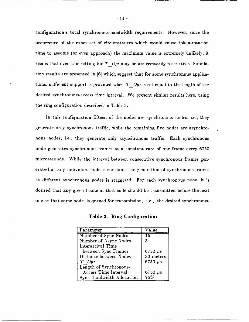
desired synchronous-access time interval. We present similar results here, using
the ring configuration described in Table 3.
In this configuration fifteen of the nodes are synchronous nodes, i.e., they
generate only synchronous traffic, while the remaining five nodes are asynchro-
nous nodes, i.e., they generate only asynchronous traffic. Each synchronous
node generates synchronous frames at a constant rate of one frame every 6750
microseconds. While the interval between consecutive synchronous frames gen-
erated at any individual node is constant, the generation of synchronous frames
a t different synchronous nodes is staggered. For each synchronous node, it is
desired that any given frame a t that node should be transmitted before the next
one at that same node is queued for transmission, i.e., the desired synchronous-
.
Table 3. Ring Configuration
Parameter Number of Sync Nodes Number of Async Nodes Interarrival Time
between Sync Frames Distance bet ween Nodes T Opr Length of Synchronous-
Access Time Interval Sync Bandwidth Allocation
Value 15 5
6750 p s 30 meters 6750 p s
6750 ps 75%
- 12 -
access time interval is 6750 microseconds. Each synchronous node is allocated
synchronous bandwidth to transmit exactly one synchronous frame each time it
receives the token. Thus, total synchronous-bandwidth allocation for the entire
network is approximately 75% of the specified T - Opr value. Note that it is
theoretically impossible to set T - Opr according to the standards document (or
according to the formula given in [6] either), because there is too much demand
for synchronous bandwidth relative to the desired frequency of channel access.
We conducted a series of simulation runs using this basic configuration,
varying the overall offered load by varying the load offered by the asynchronous
nodes. Even with the total offered load as high as 95% of capacity, all
synchronous-frame delays were less than 6750 microseconds, i.e., they were all
within the desired range.'
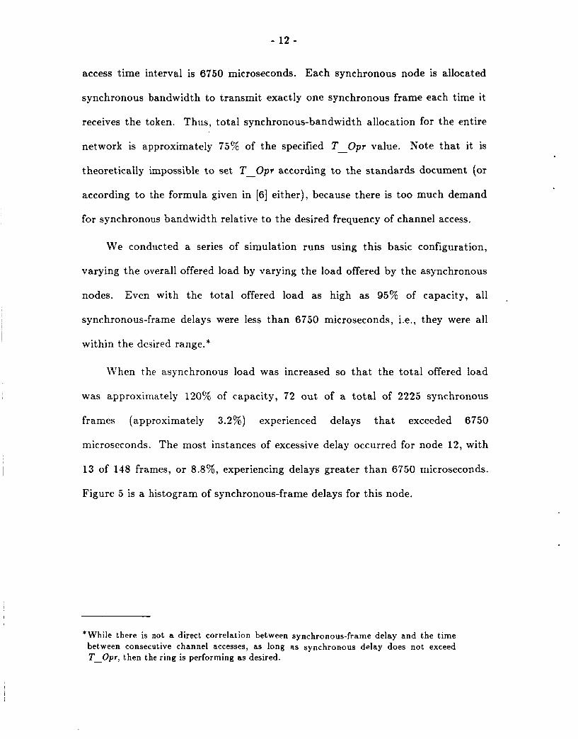
When t,he asynchronous load was increased so that the total offered load
was approximately 120% of capacity, 72 out of a total of 2225 synchronous
frames (approximately 3.2%) experienced delays that exceeded 6750
microseconds. The most instances of excessive delay occurred for node 12, with
13 of 148 frames, or 8.8%, experiencing delays greater than 6750 microseconds.
Figure 5 is a histogram of synchronous-frame delays for this node.
*While there is not a direct correlation between synchronous-frame delay and the time between consecutive channel accesses, as long as synchronous delay does not exceed T-Opr, then the ring is performing as desired.
Synchronous Frame Delay (microseconds)
Figure 5. Frequency Distribution of Synchronous Frame Delays for Node 12
As was discussed in [6], excessive delays (Le., delays greater than 6750
microseconds) tend to occur in clusters, because excessive delay for one frame
will cause frames to back up in the transmission queue. Since the synchronous
allocation for this particular configuration allows only one frame to be transmit-
ted during each token rotation, since the token-rotation time in a saturated ring
approaches T - Opr, and since an additional frame is added to the queue every
T - O p r microseconds, it may take several rotations before the queue becomes
empty again. There were five such clusters for node 12 in the above scenario.
These clusters of excessive delays can be eliminated by purging a synchronous
frame which is pending transmission when a new synchronous frame becomes
queued for transmission at the same node. If this purging technique had been
implemented in the above scenario, then only five synchronous frames from node
12 (approximately 3.4%) would have been lost, and the rest would have experi-
- 14 -
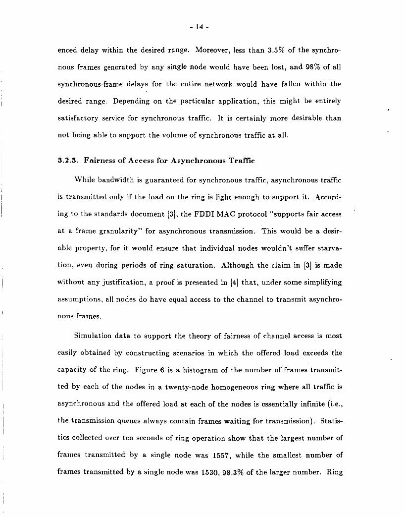
enced delay within the desired range. Moreover, less than 3.5% of the synchro-
nous frames generated by any single node would have been lost, and 98% of all
synchronous-frame delays for the entire network would have fallen within the
desired range. Depending on the particular application, this might be entirely
satisfactory service for synchronous traffic. It is certainly more desirable than
not being able to support the volume of synchronous traffic at all.
3.2.3. Fairness of Access for Asynchronous Traffic
While bandwidth is guaranteed for synchronous traffic, asynchronous traffic
is transmitted only if the load on the ring is light enough to support it. Accord-
ing to the standards document [3], the FDDI MAC protocol “supports fair access
at a frame granularity” for asynchronous transmission. This would be a desir-
able property, for it would ensure that individual nodes wouldn’t suffer starva-
tion, even during periods of ring saturation. Although the claim in [3] is made
without any justification, a proof is presented in [4] that , under some simplifying
assumptions, all nodes do have equal access to the channel to transmit asynchro-
nous frames.
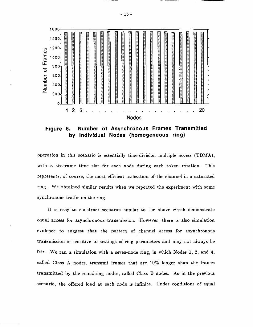
Simulation data to support the theory of fairness of channel access is most
easily obtained by constructing scenarios in which the offered load exceeds the
capacity of the ring. Figure 6 is a histogram of the number of frames transmit-
ted by each of the nodes in a twenty-node homogeneous ring where all traffic is
asynchronous and the offered load at each of the nodes is essentially infinite (Le.,
the transmission queues always contain frames waiting for transmission). Statis-
tics collected over ten seconds of ring operation show that the largest number of
frames transmitted by a single node was 1557, while the smallest number of
frames transmitted by a single node was 1530, 98.3% of the larger number. Ring
- 15 -
1 2 3 . . . . . . . . . . . . . . . . . . 20 Nodes
Figure 6. Number of Asynchronous Frames Transmitted by Individual Nodes (homogeneous ring)
operation in this scenario is essentially time-division multiple access (TDMA),
with a six-frame time slot for each node during each token rotation. This
represents, of course, the most efficient utilization of the channel in a saturated
ring. We obtained similar results when we repeated the experiment with some
synchronous traffic on the ring.
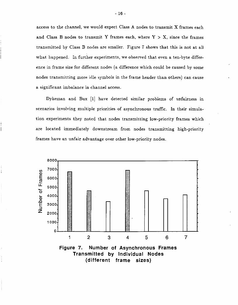
It is easy to construct scenarios similar to the above which demonstrate
equal access for asynchronous transmission. However, there is also simulation
evidence to suggest that the pattern of channel access for asynchronous
transmission is sensitive to settings of ring parameters and may not always be
fair. We ran a simulation with a seven-node ring, in which Nodes 1, 2, and 4,
called Class A nodes, transmit frames that are 10% longer than the frames
transmitted by the remaining nodes, called Class B nodes. As in the previous
scenario, the offered load a t each node is infinite. Under conditions of equal
- 16 -
access to the channel, we would expect Class A nodes to transmit X frames each
and Class B nodes to transmit Y frames each, where Y > X, since the frames
transmitted by Class B nodes are smaller. Figure 7 shows that this is not at all
what happened. In further experiments, we observed that even a ten-byte differ-
ence in frame size for different nodes (a difference which could be caused by some
nodes transmitting more idle symbols in the frame header than others) can cause
a significant imbalance in channel access.
Dykeman and Bux [l] have detected similar problems of unfairness in
scenarios involving multiple priorities of asynchronous traffic. In their simula-
tion experiments they noted that nodes transmitting low-priority frames which
are located immediately downstream from nodes transmitting high-priority
frames have an unfair advantage over other low-priority nodes.
1 2 3 4 5 6 7
Figure 7. Number of Asynchronous Frames Transmitted by Individual Nodes
(different frame sizes)
- 17 -
4. Conclusions
In this paper we have presented a performance analysis of the FDDI token-
ring protocol. Using standard measures of performance, we have shown that
average frame delay is low until the ring nears saturation; utilization follows the
ideal curve, increasing linearly until the ring reaches saturation and then leveling
off; and transmission-queue lengths remain small, until the ring reaches satura-
tion, indicating that frames are transmitted almost as soon as they are gen-
erated.
In addition, we presented simulation data to support results from earlier
analytic studies of distinctive features of the FDDI timed-token protocol. First
we demonstrated the asymptotic behavior of average token-rotation time as a
function of offered load. Then we investigated synchronous-frame delays with a
more relaxed setting of T - Opr than that specified in the standards document.
Our results indicate that the service provided when T - Opr is set equal to the
desired synchronous-access time interval would be satisfactory for applications
which can tolerate excessive delays' for a small percentage of synchronous frames.
Finally, we presented simulation data to demonstrate that the pattern of chan-
nel access for nodes transmitting asynchronous frames is sensitive to values of
ring parameters, and that access may or may not be fair, depending on the par-
ticular configuration.
.
- 18 -
References
1. D. Dykeman and W. Bux, “An Investigation of the FDDI Media Access Control Protocol,” in Proc. EFOC/LAN ’87, Basel, Switzerland, (IGI Europe), Information Gatekeepers, Inc., Boston, June, 1987, pp. 229 ff.
2. D. Dykeman and W. Bux, “Analysis and Tuning of the FDDI Media-Access Control Protocol,” to appear in IEEE J . Sel. Areas in Cornrnun., vol. SAC- 6, July 1988.
3 . FDDI Token Ring Media Access Control, American National Standard, X3.139 - 1987.
4. M. J. Johnson, “Fairness of Channel Access for Non-Time-Critical Traffic Using the FDDI Token Ring Protocol,” in Proc. Advanced Seminar on Real-Time Local Area Networks, Bandol, France, INRIA, Apr. 1986, pp. 145-1 57.
5. M. J. Johnson, “Proof that Timing Requirements of the FDDI Token Ring Protocol are Satisfied,” IEEE Trans. Commun., vol. COM-35, no. 6, pp. 620-625, 1987.
6. M. J . Johnson, “Analysis of FDDI Synchronous Traffic Delays,” in Proceed- ings of Systems Design and Networks Conference, IEEE, Apr. 1988.
7. F. E. Ross, “FDDI - A Tutorial,” IEEE Comrnun. Mag., vol. 24, no. 5, pp. 10-17, 1986.
8. K. C. Sevcik and M. J. Johnson, “Cycle Time Properties of the FDDI Token Ring Protocol,” IEEE Trans. Software Eng., vol. SE-13, no. 3, pp. 576-385, 1987.
9. J. M. Ulm, “A Timed Token Ring Local Area Network and its Performance Characteristics,” in Proc. 7th Conf. Local Comput. Networks, IEEE, Feb. 1982, pp. 50-56.

![Reliability Analysis for FDDI Dual Homing NetworksFiber Distributed Data Interface (FDDI) is a high-speed, fiber-optic token network consisting of two counter-rotat-ing rings [1]](https://img.pdfslide.net/doc/110x75/5e79b0549e0d7d41c13c46ff/reliability-analysis-for-fddi-dual-homing-networks-fiber-distributed-data-interface.jpg)