Embed Size (px)
Citation preview

Article no. 13
THE CIVIL ENGINEERING JOURNAL 2-2020
---------------------------------------------------------------------------------------------------------------
DOI 10.14311/CEJ.2020.02.0013 147
PERFORMANCE ANALYSIS OF HIGH STEEL TUBE LATTICE SUPPORT SYSTEM IN TYPHOON AREA
Shijie Wang1, Quansheng Sun1 and Jianxi Yang2
1. Department of Civil Engineering, Northeast Forestry University, Harbin150040,
China; [email protected]; [email protected];
2. College of Civil and Architectural Engineering, Heilongjiang Institute of
Technology, Harbin 150050, China; [email protected]
ABSTRACT
Research on safety of high steel tube lattice support systems in typhoon areas is still in the preliminary stage. The purpose of this paper is to study the overall buckling and overturning stability of the high steel tube lattice support systems in typhoon area. By constructing the spatial finite element model of the high steel tube lattice support system via MIDAS Civil, the optimal design of the steel tube lattice support system is carried out through the analysis of the main influencing parameters. The stability of steel pipe lattice support system is calculated theoretically, and the optimal design of steel pipe lattice support system is studied by finite element numerical method in Typhoon area. The calculation results show that Critical buckling load coefficient increases with the increase in diameter of the steel tube when the δ/d ratio of steel pipe structure is fixed. The critical load factor of the six-limb support system is slightly larger than that of the four-limb support system. When the transverse space of the support system is from 5 m to 7 m, stability increases rapidly. The best stability of the support system is obtained when the transverse space is approximately 7 m. The diagonal brace can significantly improve the stability of the steel tube lattice falsework.
KEYWORDS
High Steel Tube Lattice Support System, Stability, Finite Element Model, Wind Load
INTRODUCTION The steel tube lattice support system is widely used in the construction of long-span
bridges. However, when the support system reaches a certain height, the entire structure becomes flexible and the mechanical properties become complex. The existing research on mechanical analysis of the double limb lattice column and concrete-filled steel tube of lattice wind tower turbine [1-3] has been carried out. Some scholars also studied the mechanical properties of lattice columns by experimental and numerical methods [4-6].Some achievements have also been made in the influence of bearing capacity of lattice columns [7] and optimization design of composite tower for large wind turbine systems [8]. Furthermore, the elastic buckling [9-10] and stability of lattice columns is also very important, some research results have also been obtained [11-16].
Under wind load, forced vibration occurs in the high lattice support system, leading to changes in surface pressure that result in vibration effects [17]. Wind load generally consists of mean wind and fluctuating wind loads. Mean wind load can be approximated to the static load acting on the structure, whereas fluctuating wind load causes the dynamic response of the structure [18-19]. The influence of the fluctuating wind load on the structure must be considered; moreover, the load is important to the safety of the flexible lattice support system in typhoon areas [20]. In this study, the influence of wind load on the bracing system of steel tube lattice formwork is

Article no. 13
THE CIVIL ENGINEERING JOURNAL 2-2020
---------------------------------------------------------------------------------------------------------------
DOI 10.14311/CEJ.2020.02.0013 148
analysed, and the optimisation of the structural system is studied based on the actual project located in the typhoon area with a wind speed magnitude of 14m/s. This paper mainly studies the overall buckling and overturning stability of the high steel tube lattice support systems in typhoon area.
ESTABLISHMENT OF FINITE ELEMENT MODEL
Background
Dalian Island Bridge is located in the central area of Pingtan Strait and 7.85 km from the nearest point of the mainland. The area experiences strong winds all year round and waterways are flooded. The highway part of Dalian Island Bridge is divided into five units. The bridge span arrangement was a continuous beam with dimensions of 4 × 40 m + 4 × 40 m + 6 × 40 m + 5 × 40 m + 4 × 32 m. The pier height ranged from 13 m to 50.5 m. The main beam adopted the cast-in-place bracket construction method, which used steel tube columns and the combined structural system of Bailey beam. The flat joint and diagonal bracings between mid-spans were connected by Φ400 × 8 mm steel tubes. D9#–D19# columns utilised Φ1,200 × 14 mm steel tubes. Mid-span flat joints adopted Φ720 × 14 mm steel tubes. Diagonal bracings used Φ400 × 8 mm steel tubes. In this study, the highest bracket D10#–D11# (61.702 m) segment was selected as the research object. Figure 1 and Figure 2 show the structure form of the bracket and D10–D11 Steel tube lattice support system, respectively.
Fig.1 - On-site bracket support system (a) (b)

Article no. 13
THE CIVIL ENGINEERING JOURNAL 2-2020
---------------------------------------------------------------------------------------------------------------
DOI 10.14311/CEJ.2020.02.0013 149
1355
6000
12
00
06000
12
00
012000
60
00
63
47
7610
61702
3000 支座中心线
9000 9000
62022
1355
6000
12000
60
00
12000
60
00
12
00
06347
61
70
2
1500
Fig. 2 - D10–D11 Steel tube lattice support system (a) longitudinal and (b) cross-section views
Finite element Model
MIDAS/Civil software was used to establish the finite element model for the high falsework. The model set the node at the connecting point of the member and connection of the foundation. Elements were divided based on the actual steel structure. The high steel tube lattice falsework was composed of 3,688 nodes and 6,993 elements. Bailey beams and steel tube lattice brackets were modelled as truss and beam elements, respectively. Figure 3 and Figure 4 present the falsework finite element discrete model and 3D finite element models of the falsework, respectively. The maximum wind load in the working state of the falsework was considered a grade 8 wind, and the wind speed was 20.7 m/s. The wind load of the nonworking state was considered in the 10-year typhoon period, and the wind speed was 45.4 m/ s.
Fig. 3 - Falsework Finite Element Discrete Model Fig. 4 - 3D Falsework Finite Element model

Article no. 13
THE CIVIL ENGINEERING JOURNAL 2-2020
---------------------------------------------------------------------------------------------------------------
DOI 10.14311/CEJ.2020.02.0013 150
FORMWORK SUPPORT SYSTEM CALCULATION AND STABILITY ANALYSIS
Details of Formwork support on working stage conditions are shown in Table1.
Tab. 1 - Details on working stage conditions
Condition Description Load combination Purpose
C-I Shoring tower completed, prior to rebar installation, nonworking
stage
0.9 × (② + ③ + ⑦) Structure and overturning stability
verification
C-II Concrete casting, prior to stretch prestressing, nonworking stage
1.2 (① + ②)+ 0.9 × 1.4
(③ + ④ + ⑤ + ⑦)
Shoring tower stability verification
C-III Concrete casting completed, shoring towers are now load
bearing
1.2 (① + ②)+ 1.4 (③ + ⑦) Shoring tower robustness verification
C-IV Normal working stage ① + ② Shoring tower stiffness verification
In Table 1: ① Reinforced concrete bulk density of main beam: 26 kN/m3.
② Formwork deadweight: 3.0 kN/m2.
③ Construction crew, materials and construction machines and tool load:
a. For shoring column calculations, load was uniformly distributed at 2 kN/m2.
b. For horizontal and diagonal brace calculation, load as uniformly distributed at 1.5 kN/m2.
c. Props and other accessory structures were at 1 kN/m2.
④ Vibration load: Load generated by mixing concrete was 2 kN/m2.
⑤ Impact load: Impact generated when pouring and casting concrete was 2 kN/m2.
⑥ Dead weight of falsework system: Bailey beam and steel lattice column were 78.5 kN/m3.
⑦ Static wind load: Static wind load was calculated according to ‘Load Code for the Design of
Building Structures’ as follows:
𝑤𝑘 = 𝛽𝑧𝜇𝑧𝜇𝑠𝑤0 (1) where:
wk—standard value of wind load (kN/m2) βz—wind vibration coefficient at height z is 1.0 μs—wind load shape factor, column and Bailey beams are considered and calculated as
round tubes and truss beams, respectively μz—wind pressure height coefficient is 2.12
w0—basic wind pressure (kN/m2), 𝑤0=𝑣2/1600

Article no. 13
THE CIVIL ENGINEERING JOURNAL 2-2020
---------------------------------------------------------------------------------------------------------------
DOI 10.14311/CEJ.2020.02.0013 151
Formwork Support System Design and Calculation
Internal force and stress of bailey beam, cross beam, column and bracket connection system (horizontal and oblique brace) were calculated. Under the most unfavourable circumstances, the maximum axial force of the main chord in Bailey beam, vertical bar and oblique rod were −390.16, −192.13 and 139.15 kN, respectively. The maximum stress of the vertical column, the maximum displacement of the falsework, the maximum sheer force of the connection joints and the maximum stress were −126.81 MPa, 21.46 mm, −150.41kN and −84.14 MPa, respectively. According to design code of steel structures, the design value for the upper and lower chords of Bailey beams, vertical columns and diagonal bracings were 510, 193 and 156kN, respectively. The design compressive strength of grade Q235 steel was 195 MPa. Therefore, actual load as lower than designed bearing load of the structure, and strength of the structure fulfilled the load-bearing requirements.
Stability Analysis
The lattice column at mid-span bears not only the bending moment. My caused by the asymmetry of the bridge construction but also the bending moment Mx caused by the longitudinal wind load. The lattice column was the crucial part under the eccentric compression state, causing the column to be under the state of bidirectional bending. The stability was related to all three variables N, Mx and My. Lattice column falsework section property and internal force calculation results are shown in Table 2 and Table 3.
Tab. 2 - Lattice column falsework section property
A (cm2) W (cm3) I (cm4) EA (kN)
522 15,288 1,834,563 1,075,320
Tab. 3 - Lattice column falsework internal force calculation results
Condition Axle force, N
(kN)
Bending moment, Mx
(kN·m)
Bending moment, My
(kN·m)
C-I 1,063 29 102
C-II 4,067 94 148
(1) Working stage condition C-I
At condition C-I, the falsework was completed but under the nonworking state. Overall analysis on buckling and stability was conducted. The results are as follows:
a. Buckling Stability
Slenderness ratio:𝜆𝑥=λ𝑦= 𝐿 𝑖 = 10000 420 = 23.8⁄⁄ , based on type B cross section and
stability coefficient𝜑𝑥 = 𝜑𝑦 = 0.957.
If E = 206,000,000 kN/m2, then A = 0.00522 m2,𝜆𝑥 = 23.8,then𝑁′𝐸𝑥 can be calculated as
follows:
𝑁′𝐸𝑥 =𝜋2𝐸𝐴
1.1𝜆𝑥2 =
𝜋2×206000000×0.00522
1.1×23.82 = 17016𝑘𝑁
σ1 =𝑁
𝜑𝑥𝐴+
𝛽𝑚𝑥𝑀𝑥
𝛾𝑥𝑊𝑥(1−0.8𝑁
𝑁′𝐸𝑥)
+ 𝜂𝛽𝑡𝑦𝑀𝑦
𝜑𝑏𝑦𝑊𝑦= 27.7𝑀𝑃𝑎 < 𝑓 = 195𝑀𝑃𝑎

Article no. 13
THE CIVIL ENGINEERING JOURNAL 2-2020
---------------------------------------------------------------------------------------------------------------
DOI 10.14311/CEJ.2020.02.0013 152
σ2 =𝑁
𝜑𝑦𝐴+
𝛽𝑚𝑦𝑀𝑦
𝛾𝑦𝑊𝑦(1−0.8𝑁
𝑁′𝐸𝑦)
+ 𝜂𝛽𝑡𝑥𝑀𝑥
𝜑𝑏𝑥𝑊𝑥= (21.3 + 1.3 + 6.1)𝑀𝑃𝑎 = 28.7𝑀𝑃𝑎 < 𝑓 = 195𝑀𝑃𝑎
Therefore, the falsework is in good stability under this working stage condition.
b.Anti-overturning Stability:
Overturning stability of the shoring tower under nonworking stage was analysed according to the following equation:
𝑘 =𝑀𝑘
𝑀𝑞
𝑀𝑘 = 6000 × 30 2 = 90000𝑘𝑁 ∙ 𝑚⁄ 𝑀𝑞 = 𝑀𝑓𝑜𝑟𝑚𝑤𝑜𝑟𝑘 + 𝑀𝑠𝑡𝑒𝑛𝑡 = 124 × 60 × 1.28 + 162 × 30 × 1.28 = 15744𝑘𝑁 ∙ 𝑚
𝑘 =90000
15744= 5.7 > 1.5
The calculated overturning stability coefficient was 5.7, which was significantly larger than that required in the design code. Therefore, overturning stability was high.
(2) Condition C-II
At condition C-II, the beams on top of the falsework completed casting, but prestressing
was not stretched and under the nonworking state. The calculation process is as follows:
σ1 =𝑁
𝜑𝑥𝐴+
𝛽𝑚𝑥𝑀𝑥
𝛾𝑥𝑊𝑥(1−0.8𝑁
𝑁′𝐸𝑥)
+ 𝜂𝛽𝑡𝑦𝑀𝑦
𝜑𝑏𝑦𝑊𝑦= 94.8𝑀𝑃𝑎 < 𝑓 = 195𝑀𝑃𝑎
σ2 =𝑁
𝜑𝑦𝐴+
𝛽𝑚𝑦𝑀𝑦
𝛾𝑦𝑊𝑦(1−0.8𝑁
𝑁′𝐸𝑦)
+ 𝜂𝛽𝑡𝑥𝑀𝑥
𝜑𝑏𝑥𝑊𝑥= 96.4𝑀𝑃𝑎 < 𝑓 = 195𝑀𝑃𝑎
Stability under condition C-II met the requirement.
OPTIMAL DESIGN OF STEEL TUBE LATTICE FALSEWORK
Influence of Steel Tube Diameter The falsework column was assumed to have identical cross sections. The force line of the
column was consistent with the longitudinal axis of the cross section, and the material was completely uniform and elastic. The critical load of the column could be obtained by using the Euler critical force formula.
The ratio of the wall thickness δ to the diameter d of the steel tube was considered the control parameter. By solving the buckling stability coefficient of columns with different diameter and thickness values, the optimum diameter and thickness were obtained, as shown in Figure 5.
700 800 900 1000 1100 1200 1300 1400 15000
1
2
3
4
5
6
7
8
9
10
11
12
13
bu
cklin
g s
tab
ility
coeff
icie
nt
steel Tube diameter(mm)
δ/d=0.019
δ/d=0.012
δ/d=0.009
Fig. 5 - Comparison of the different δ/d ratios and buckling coefficients
Article no. 13
THE CIVIL ENGINEERING JOURNAL 2-2020
---------------------------------------------------------------------------------------------------------------
DOI 10.14311/CEJ.2020.02.0013 153
Figure 5 shows that the critical buckling load coefficient increases at an exponential rate as the diameter of the steel tube increases when δ/d ratio is fixed. When the diameter of the steel tube was constant, the critical load coefficient of the structure increased with the increase in wall thickness. The enlarged diameter of steel pipe increases the change in the critical load coefficient. Therefore, the cross-section size of the structure was the main factor affecting the stability of falsework.
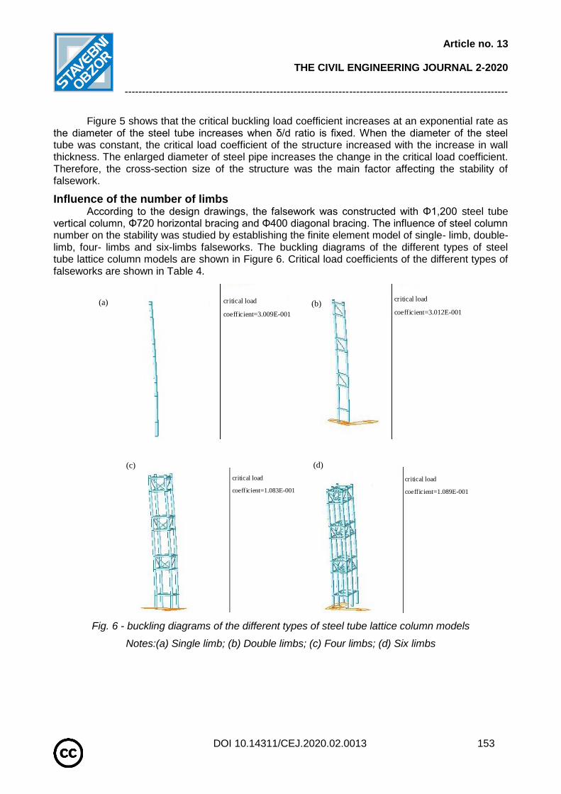
Influence of the number of limbs According to the design drawings, the falsework was constructed with Φ1,200 steel tube
vertical column, Φ720 horizontal bracing and Φ400 diagonal bracing. The influence of steel column number on the stability was studied by establishing the finite element model of single- limb, double- limb, four- limbs and six-limbs falseworks. The buckling diagrams of the different types of steel tube lattice column models are shown in Figure 6. Critical load coefficients of the different types of falseworks are shown in Table 4.
critical load
coefficient=3.009E-001
critical load
coefficient=3.012E-001
critical load
coefficient=1.083E-001
critical load
coefficient=1.089E-001
Fig. 6 - buckling diagrams of the different types of steel tube lattice column models
Notes:(a) Single limb; (b) Double limbs; (c) Four limbs; (d) Six limbs
(a) (b)
(c) (d)

Article no. 13
THE CIVIL ENGINEERING JOURNAL 2-2020
---------------------------------------------------------------------------------------------------------------
DOI 10.14311/CEJ.2020.02.0013 154
Tab. 4 - Critical load coefficient of the different types of falseworks
Limb(s) Critical Load Coefficient
Model Diagram
Configuration
Single 0.30 (a) —
Double 0.31 (b) 9 m spacing
Four 10.83 (c) 9 m transverse, 7.61 m longitudinal
Six 10.89 (d) 2 × 9 m transverse, 7.61 m longitudinal
Figure 6 results of buckling calculations and data from Table 4 show the critical load
coefficient calculated value of single- and double-limb structures were close, thereby the result indicated that stability of the double-limb structure was almost similar to that of the single-limb structure. However, when the number of limbs increased to four, the critical load coefficient also increased significantly. The stability of the lattice column improved at this time as the resistance to external load also increased. When the number of limbs increased to six, the critical load coefficient increased to less than 4 limbs, thereby indicating that the four-limb steel tubular column was the most cost-effective option.
Influence of Segment length and Height When the height of the falsework was high, the high falsework was usually divided into
segments with lengths of 9, 12, 15 and 18 m. The critical load coefficient at heights 30, 40, 50, 60, 70 and 80 m was analysed, and the critical load coefficient in the first three orders buckling of falsework was obtained. The critical load coefficient of different segment Lengths of falsework is shown in Table 5. Figure 7 and Figure 8 show the first-order and second-order critical load coefficient results at different segment height.

Article no. 13
THE CIVIL ENGINEERING JOURNAL 2-2020
---------------------------------------------------------------------------------------------------------------
DOI 10.14311/CEJ.2020.02.0013 155
Tab.5 - Critical load coefficient of Different Segment Lengths
Segment Length (m)
Falsework Height (m)
first-order buckling
Second -order buckling
Third -order buckling
9 30 8.08 8.57 11.61 40 7.89 8.28 11.60 50 7.70 7.69 11.59 60 7.47 7.63 11.59 70 7.17 7.30 11.59 80 6.74 7.02 11.58
12 30 6.77 7.23 10.88 40 6.61 6.99 10.87 50 6.45 6.73 10.86 60 6.28 6.46 10.86 70 6.08 6.18 10.86 80 5.79 5.93 10.85
15 30 5.72 6.14 10.39 40 5.60 5.94 10.37 50 5.47 5.72 9.46 60 5.33 5.51 10.36 70 5.18 5.28 9.66 80 4.99 5.07 9.80
18 30 4.56 4.92 10.02 40 4.77 5.06 10.01 50 4.67 4.90 9.35 60 4.55 4.71 6.62 70 4.44 4.55 8.36 80 4.31 4.34 7.43
30 40 50 60 70 804.0
5.0
6.0
7.0
8.0
9.0
Criti
cal lo
ad
co
eff
icie
nt
Height H(m)
9m
12m
15m
18m
30 40 50 60 70 80
4.0
5.0
6.0
7.0
8.0
9.0 9m
12m
15m
18m
Criti
cal lo
ad
co
eff
icie
nt
Height H(m)
Fig. 7 - First-order critical load coefficient Fig. 8 - Second-order critical Load coefficient
The data from Table 5 show that the critical coefficient of the third-order load is significantly larger than that of the first two-order load at the different segment height, thereby indicating that the structure can hardly reach its third stage of instability. Failure mainly occurred in the first two stages of loading. Figure 7 and Figure 8 illustrate that the critical load coefficient decreases as falsework height increases, thereby indicating poor stability. However, critical load coefficient was guaranteed to exceed 4.0, which satisfied the basic stability requirement when structure segment was not more than 18 m. By contrast, the critical load coefficient decreases drastically when falsework is more than 70 m high. Therefore, in the falsework design, the reasonable segment length and total height of the falsework could be selected based on the different critical coefficients.

Article no. 13
THE CIVIL ENGINEERING JOURNAL 2-2020
---------------------------------------------------------------------------------------------------------------
DOI 10.14311/CEJ.2020.02.0013 156
Influence of Transverse and longitudinal Spacing
The longitudinal and transverse spacing of a steel tube column was an important parameter that reflected the support area. To study the effect of longitudinal and transverse distances on stability, falsework with segment length and height of 12 and 60 m were used, respectively. With varying transverse and longitudinal spacing, critical load coefficients were calculated. Critical Load coefficient of different spacing of falsework is shown in Table 6.
Tab. 6 - Critical Load coefficient of different spacing
Transverse and Longitudinal spacing Critical Load Coefficient
5 m × 5 m 5.66 6 m × 6 m 6.20 7 m × 7 m 6.39 8 m × 8 m 6.38 9 m × 9 m 6.26
10 m × 10 m 6.09
Figure 9 shows that spacing and critical load coefficient were set as the x- and y-axes
based on the values in Table 6.
5 6 7 8 9 105.6
5.7
5.8
5.9
6.0
6.1
6.2
6.3
6.4
6.5
Criti
cal lo
ad
co
eff
icie
nt
Longitudinal and transverse spacing(m)
Fig. 9 -Transverse spacing versus critical load coefficient graph
Figure 9 shows that the relationship between the critical load coefficient and the transverse spacing is a parabolic curve. When the latticed column spacing was less than 6 m, the change was rapid and exponential. The rate of increase in the critical load coefficient decreased when the latticed column spacing was 6–7 m. The critical load coefficient reached the peak value at 7 m. The curve reached a plateau immediately after transverse spacing reached 7 m. Therefore, the falsework obtained the most stable and safest condition at spacing of around 7 m.
Influence of Diagonal Bracing
For lattice columns, lateral bracing was essential to maintain its stability, whereas the effect of diagonal bracing must still be determined. Finite element software was used to simulate the influence of braces on the stability of the lattice support. The first three stages of instability modes for structures with and without diagonal braces are shown in Figure 10.
Figure 10 shows that the critical load coefficient of the first-stage load is 6.28 and 4.91 with and without diagonal brace respectively.

Article no. 13
THE CIVIL ENGINEERING JOURNAL 2-2020
---------------------------------------------------------------------------------------------------------------
DOI 10.14311/CEJ.2020.02.0013 157
critical load
coefficient=6.282E+000
4.88277e-004
4.43888e-004
3.99500e-004
3.55111e-004
3.10722e-004
2.66333e-004
2.21944e-004
1.77555e-004
1.33167e-004
8.87777e-005
4.43888e-005
0.00000e+000
critical load
coefficient=4.914E+000
7.36449e-004
6.69499e-004
6.02549e-004
5.35599e-004
4.68649e-004
4.01699e-004
3.34749e-004
2.67800e-004
2.00850e-004
1.33900e-004
6.69499e-005
0.00000e+000
critical load
coefficient=6.460E+000
4.58559e-004
4.12703e-004
3.66848e-004
3.20992e-004
2.75136e-004
2.29280e-004
1.83424e-004
1.37568e-004
9.17119e-005
4.58559e-005
0.00000e+000
5.04415e-004
critical load
coefficient=5.178E+000
7.20926e-004
6.55388e-004
5.89849e-004
5.24310e-004
4.58771e-004
3.93233e-004
3.27694e-004
2.62155e-004
1.96616e-004
1.31078e-004
6.55388e-005
0.00000e+000
critical load
coefficient=1.086E+001
2.87406e-004
2.61278e-004
2.35150e-004
2.09022e-004
1.82894e-004
1.56767e-004
1.30639e-004
1.04511e-004
7.83833e-005
5.22556e-005
2.61278e-005
0.00000e+000
critical load
coefficient=8.078E+000
4.52421e-004
4.11292e-004
3.70163e-004
3.29034e-004
2.87905e-004
2.46775e-004
2.05646e-004
1.64517e-004
1.23388e-004
8.22584e-005
4.11292e-005
0.00000e+000
Fig. 10 - Stability of Shoring Tower with and without Diagonal Brace (a) First Stage with Diagonal
Brace;(b) First Stage without Diagonal Brace; (c) Second Stage with Diagonal Brace;(d) Second
Stage without Diagonal Brace; (e) Third Stage with Diagonal Brace; (f) Third Stage without
Diagonal Brace
Figure 10 shows that the diagonal brace increased the critical load coefficient by 27.9%. The critical load coefficient of the second stage was 6.46 and 5.18 with and without diagonal brace, respectively. An increase of 24.7% in the critical load coefficient was not a significant improvement
(c) (d)
(e) (f)
(a) (b)

Article no. 13
THE CIVIL ENGINEERING JOURNAL 2-2020
---------------------------------------------------------------------------------------------------------------
DOI 10.14311/CEJ.2020.02.0013 158
compared with that of the first stage. The 34.4% improvement in critical load coefficient of the third stage was 10.86 and 8.08 with and without diagonal brace, respectively. Therefore, diagonal bracing significantly improved stability, especially during structure failure under higher orders of loading. Diagonal bracings should be considered an essential component in the design of high steel tube lattice support systems.
CONCLUSION The finite element model of steel tube lattice column formwork support system in typhoon
construction sites is established to ensure that the strength of the support system can meet the design requirements under the most unfavourable load conditions. The falsework-latticed column is simplified as a bidirectional bending member, and the stability of the falsework is calculated. The results show that the falsework meets the stability requirements. The influence of steel tube diameter, limb number, segment length, height, spacing and the presence of oblique braces on the critical load coefficient of the support structure is studied, and the optimal design size of the falsework is obtained. This study can provide a reference for similar types of falsework construction. The main results are as follows: (1) When the ratio of wall thickness δ to diameter d of latticed column is fixed, the critical load coefficient increases rapidly with the increase in steel tube diameter d. As δ/d increases, the stability of the falsework is enhanced. (2) Four-limb high steel tube lattice column is more stable than double- or single-limb structures, but the difference is not much compared with the bearing capacity of the six-limb structure. Therefore, four-limb high steel tube lattice column is the most cost-effective solution. (3) When the total height of the lattice column is constant, the small segment length enhances the stability of the structure, but the total height should not exceed 70 m. When the total height is more than 70 m, the stability of the falsework structure is poor. Considering the economy of the material used for the latticed column, the maximum length of the segment should not exceed 3 times the length of the joint system to ensure the stability of the structure effectively. (4) When the longitudinal and transverse spacing of the latticed column falsework is 5–7 m, the stability of the falsework increases rapidly and reaches the peak at around 7 m. When the longitudinal and transverse spacing is greater than 7 m, the stability of the falsework decreases gradually. (5) The critical load coefficient of the latticed column is 27.9% higher than that of the non-inclined brace, and the stability of latticed column is significantly improved by using the oblique brace.
ACKNOWLEDGEMENTS
This paper is supported by the Harbin Talent Fund Project (grant number: RC2017QN012019)
REFERENCES [1] Li Fengyun. ,2014. Mechanical Analysis of the Double Limb Lattice Column-Bailey Beam Formwork
Supports System in Space, dissertation for the degree of master, Chongqing University, Chongqing, pp.55-
78
[2] Liu Xiang,Wang Min,Li Jian. ,2010. The Force Analysis of Concrete-filled Steel Tube of Lattice Wind
Tower Turbine, Journal of Wuhan University of Technology, Vol.32 No.9: 175-177.
[3] Hu Bin, Wu Lin-Zhi,Xiong Jian.,2019.Mechanical properties of a node-interlocking pyramidal welded
tube lattice sandwich structure, Mechanics of Materials, No.129: 290-305.
[4] Xu F, Chen J, Jin W.,2014.Experimental investigation of thin-walled concrete-filled steel tube
columns with reinforced lattice angle.Steel Construction, Vol.84:59-67.
[5] Huang F Y, Yu G, Chen B C , et al.,2014.Experiment Study on Influence of Initial Stress in Concrete
Filled Steel Tubular Latticed Columns under Axial Load. Applied Mechanics and Materials, Vol.518:170-177.
Article no. 13
THE CIVIL ENGINEERING JOURNAL 2-2020
---------------------------------------------------------------------------------------------------------------
DOI 10.14311/CEJ.2020.02.0013 159
[6] Paluch M J, Cappellari T O, Riera J D.,2007.Experimental and numerical assessment of EPS wind
action on long span transmission line conductors. Journal of Wind Engineering & Industrial
Aerodynamics,Vol.95 No.7,pp.473–492.
[7] Yin Haiyun, Yin Haixiong.,2012.The influence of double oblique Bar on the bearing capacity of
Lattice columns.Architectural Design Management, No.10:70-72
[8] Chen Junling, Yang Rongchang, Ma Renle.,2015.Structural Design Optimization of a Composite
Tower for Large Wind Turbine Systems.Journal of Hunan University (Natural Sciences), Vol.42 No.5:.29-35
[9] Lan Yong, Guo Yanlin, Chen Guodong. ,2002.Elastic Buckling Behavior of Shuttle-shape Steel
Latticed Column. Journal of Building Structures, Vol.23 No.5:18-24.
[10] Thomas See , Richard E. McConnel. ,1986.Large displacement elastic buckling of space
structures.Journal of Structural Engineering,1986, Vol.112 No.5: 1052-1069.
[11] Tian Wei,Zhao Yang,Xiang Xin-an,Dong Shi-lin.,2010. Stability Behavior of Shuttle-Shaped Steel
Lattice Columns With Bending Moment. Journal of Civil, Architectural & Environmental Engineering, Vol.32
No.6:22-27.
[12] Guo Y , Wang J .,2009.Instability behavior and application of prismatic multi-tube latticed steel
column, Journal of Constructional Steel Research, Vol.65 No.1:12-22.
[13] Zhang Liuyu.,2016. Study on Stability and Status Monitoring Technology of Cuplok Scaffold System
in Bridge Construction, dissertation for the degree of doctor, Chang'an University, Xi'an:77-156.
[14] Yang Chunlai,Wu Qiong. ,2015). Stability calculation of cast-in-situ support for Wulitang right Line
extra-large continuous Box girder Bridge, Jiangxi Building Materials, No.04:130-135
[15] Ma Li. ,2012. Analysis on Dynamic Characteristics and Dynamic Stability of Fastener-style Tubular
Formwork Support, dissertation for the degree of master, Chang'an University, Xi'an:45-62.
[16] Liu Zhifang.,2014.Study on Crucial Technique of Construction Control for Long-span Steel Truss
Arch Bridges in Typhoon Area, South China University of Technology: 33-50
[17] Jiang Jinchen.,2017.Study on Wind-induced response of long-span Pipeline suspension Bridge in
Xiaobi River.dissertation for the degree of master, Southwest Petroleum University, Chengdu:59-88.
[18] Lv Yanxia. ,2013. Dynamic Study on the Wind Load of Steel TV Tower. dissertation for the degree of
master, Zhengzhou University, Zhengzhou:19-38.
[19] Zhao Lin, Ge Yaojun, Xiang Haifan. ,2004.Prediction of Extreme Wind Speed based on Numerical
Simulation of Typhoon. Proceedings of the 11th National Conference on structural Wind Engineering:105-
110.
[20] Zhan Yanyan, Zhao Lin, Liang Yuwen. et al.,2017.Comprehensive Assessment of Wind-Induced
Interference Criteria about Large Cooling Towers with Typical Six-Towers Double-Columns Arrangements.
Engineering Mechanics, Vol.34 No.11:66-76.