Embed Size (px)
Citation preview
Performance Analysis of LTE-Advanced Physical Layer
M.A.Mohamed1, H.M.Abd-ElAtty2, M.E.A.AboEl-Seoud3 and W.M.Raslan4
1,3 Electronics and Communications Dept. , Mansoura University
Mansoura, Egypt
2 Electronics and Communications Dept. , Port Said University
Port Said, Egypt
4 Electronics and Communications Dept. , Sinai University
Arish, Egypt
Abstract LTE-Advanced (LTE-A) is the project name of the evolved
version of LTE that is being developed by 3GPP. LTE-A will
meet or exceed the requirements of the International
Telecommunication Union (ITU) for the Fourth Generation (4G)
radio communication standard known as IMT-Advanced. LTE-A
is being specified initially as part of Release 10 of the 3GPP
specifications. In this paper, we present an in-depth analysis of
the LTE-A downlink physical layer characteristics and its
performance. Our work is unique in providing a detailed
performance study based on Release 10 of the 3GPP standard. As
performance metrics, Bit Error Rate (BER) and date throughput
are evaluated in terms of Signal to Noise Ratio (SNR) for two
different Multi-Input Multi-Output (MIMO) schemes as defined
in LTE standard under different combination of digital
modulation schemes.
This study consider a first step to perform hardware
implementation of LTE-A system using Field Programmable
Gate Array (FPGA) technology that become a very important
task for mobile communication and wireless network researchers.
Keywords: Long Term Evolution (LTE), Long Term Evolution
Advanced (LTE-A), Multi-Input Multi-Output (MIMO), Evolved
Node B (eNB), User Equipment (UE), Codeword Bit Error Rate
(CBER), Data Throughput.
1. Introduction
Wireless communications have evolved from the so-called
second generation (2G) systems of the early 1990s, which
first introduced digital cellular technology, through the
deployment of third generation (3G) systems with their
higher speed data networks to the much-anticipated fourth
generation technology being developed today. This
evolution is illustrated in Fig.1, which shows that fewer
standards are being proposed for 4G than in previous
generations, with only two 4G candidates being actively
developed today: 3GPP LTE-Advanced and IEEE
802.16m, which is the evolution of the WiMAX standard
known as Mobile WiMAX [1].
The Long Term Evolution project was initiated in 2004.
The motivation for LTE included the desire for a reduction
in the cost per bit, the addition of lower cost services with
better user experience, the flexible use of new and existing
frequency bands, a simplified and lower cost network with
open interfaces, and a reduction in terminal complexity
with an allowance for reasonable power consumption.
These high level goals led to further expectations for LTE,
including reduced latency for packets, and spectral
efficiency improvements above Release 6 high speed
packet access (HSPA) of three to four times in the
downlink and two to three times in the uplink. Flexible
channel bandwidths - a key feature of LTE - are specified
at 1.4, 3, 5, 10, 15, and 20 MHz in both the uplink and the
downlink. This allows LTE to be flexibly deployed where
other systems exist today, including narrowband systems
such as GSM and some systems in the U.S. based on
1.25MHz.
Unlike previous systems, LTE is designed from the
beginning to use MIMO technology, which results in a
more integrated approach to this advanced antenna
technology than does the addition of MIMO to legacy
system such as HSPA.
Fig.1 Wireless evolution 1990-2011 and beyond.
IJCSI International Journal of Computer Science Issues, Vol. 11, Issue 1, No 1, January 2014 ISSN (Print): 1694-0814 | ISSN (Online): 1694-0784 www.IJCSI.org 80
Copyright (c) 2014 International Journal of Computer Science Issues. All Rights Reserved.
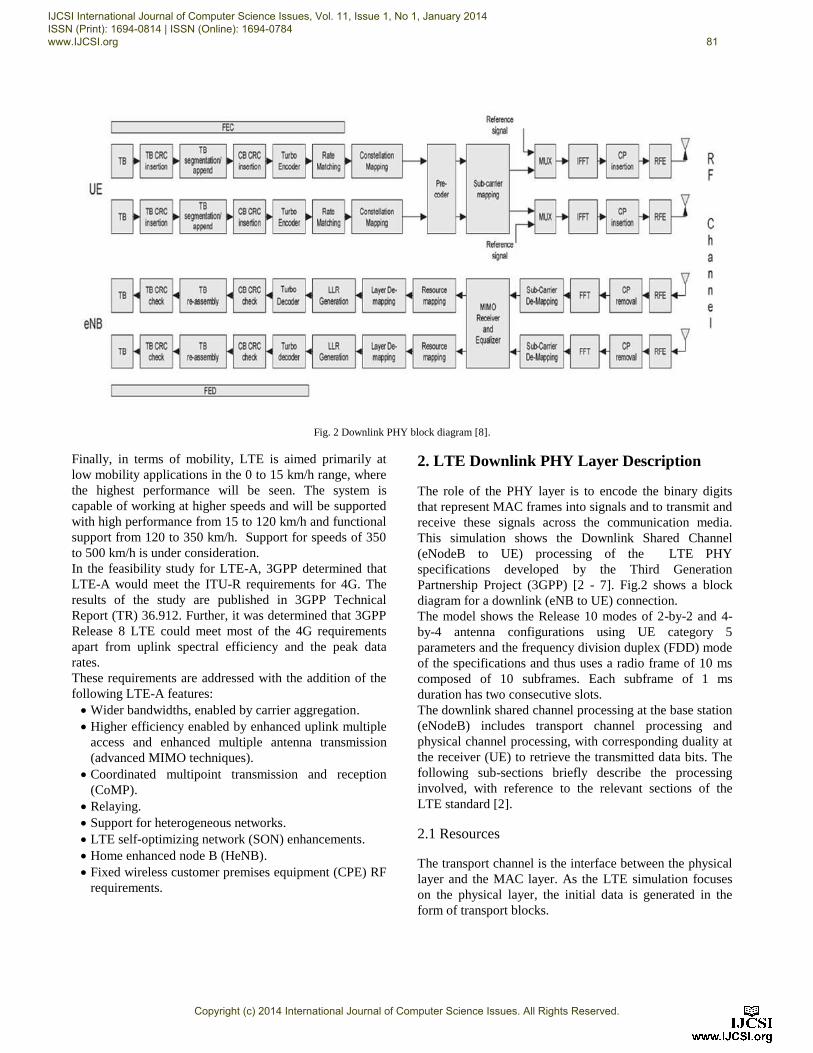
Fig. 2 Downlink PHY block diagram [8].
Finally, in terms of mobility, LTE is aimed primarily at
low mobility applications in the 0 to 15 km/h range, where
the highest performance will be seen. The system is
capable of working at higher speeds and will be supported
with high performance from 15 to 120 km/h and functional
support from 120 to 350 km/h. Support for speeds of 350
to 500 km/h is under consideration.
In the feasibility study for LTE-A, 3GPP determined that
LTE-A would meet the ITU-R requirements for 4G. The
results of the study are published in 3GPP Technical
Report (TR) 36.912. Further, it was determined that 3GPP
Release 8 LTE could meet most of the 4G requirements
apart from uplink spectral efficiency and the peak data
rates.
These requirements are addressed with the addition of the
following LTE-A features:
Wider bandwidths, enabled by carrier aggregation.
Higher efficiency enabled by enhanced uplink multiple
access and enhanced multiple antenna transmission
(advanced MIMO techniques).
Coordinated multipoint transmission and reception
(CoMP).
Relaying.
Support for heterogeneous networks.
LTE self-optimizing network (SON) enhancements.
Home enhanced node B (HeNB).
Fixed wireless customer premises equipment (CPE) RF
requirements.
2. LTE Downlink PHY Layer Description
The role of the PHY layer is to encode the binary digits
that represent MAC frames into signals and to transmit and
receive these signals across the communication media.
This simulation shows the Downlink Shared Channel
(eNodeB to UE) processing of the LTE PHY
specifications developed by the Third Generation
Partnership Project (3GPP) [2 - 7]. Fig.2 shows a block
diagram for a downlink (eNB to UE) connection.
The model shows the Release 10 modes of 2-by-2 and 4-
by-4 antenna configurations using UE category 5
parameters and the frequency division duplex (FDD) mode
of the specifications and thus uses a radio frame of 10 ms
composed of 10 subframes. Each subframe of 1 ms
duration has two consecutive slots.
The downlink shared channel processing at the base station
(eNodeB) includes transport channel processing and
physical channel processing, with corresponding duality at
the receiver (UE) to retrieve the transmitted data bits. The
following sub-sections briefly describe the processing
involved, with reference to the relevant sections of the
LTE standard [2].
2.1 Resources
The transport channel is the interface between the physical
layer and the MAC layer. As the LTE simulation focuses
on the physical layer, the initial data is generated in the
form of transport blocks.
IJCSI International Journal of Computer Science Issues, Vol. 11, Issue 1, No 1, January 2014 ISSN (Print): 1694-0814 | ISSN (Online): 1694-0784 www.IJCSI.org 81
Copyright (c) 2014 International Journal of Computer Science Issues. All Rights Reserved.
In the spatial multiplexing transmission mode, two
transport blocks at the same time are prepared for
transmission.
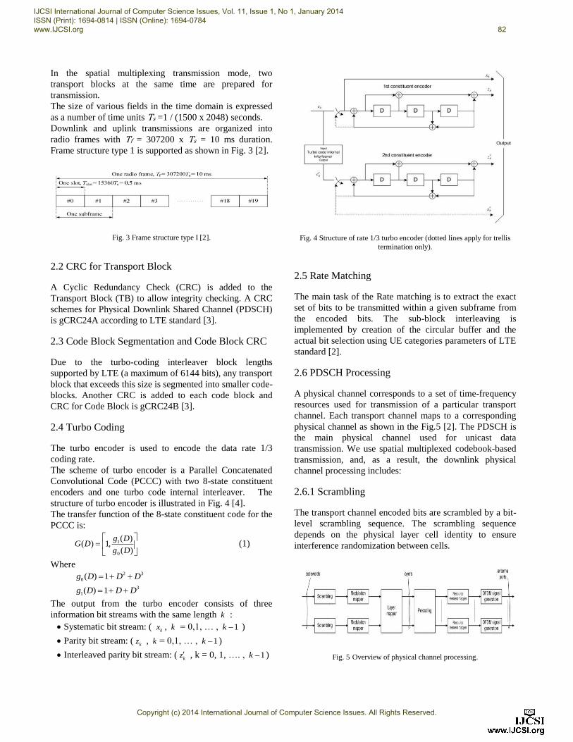
The size of various fields in the time domain is expressed
as a number of time units Ts =1 / (1500 x 2048) seconds.
Downlink and uplink transmissions are organized into
radio frames with Tf = 307200 x Ts = 10 ms duration.
Frame structure type 1 is supported as shown in Fig. 3 [2].
Fig. 3 Frame structure type I [2].
2.2 CRC for Transport Block
A Cyclic Redundancy Check (CRC) is added to the
Transport Block (TB) to allow integrity checking. A CRC
schemes for Physical Downlink Shared Channel (PDSCH)
is gCRC24A according to LTE standard [3].
2.3 Code Block Segmentation and Code Block CRC
Due to the turbo-coding interleaver block lengths
supported by LTE (a maximum of 6144 bits), any transport
block that exceeds this size is segmented into smaller code-
blocks. Another CRC is added to each code block and
CRC for Code Block is gCRC24B [3].
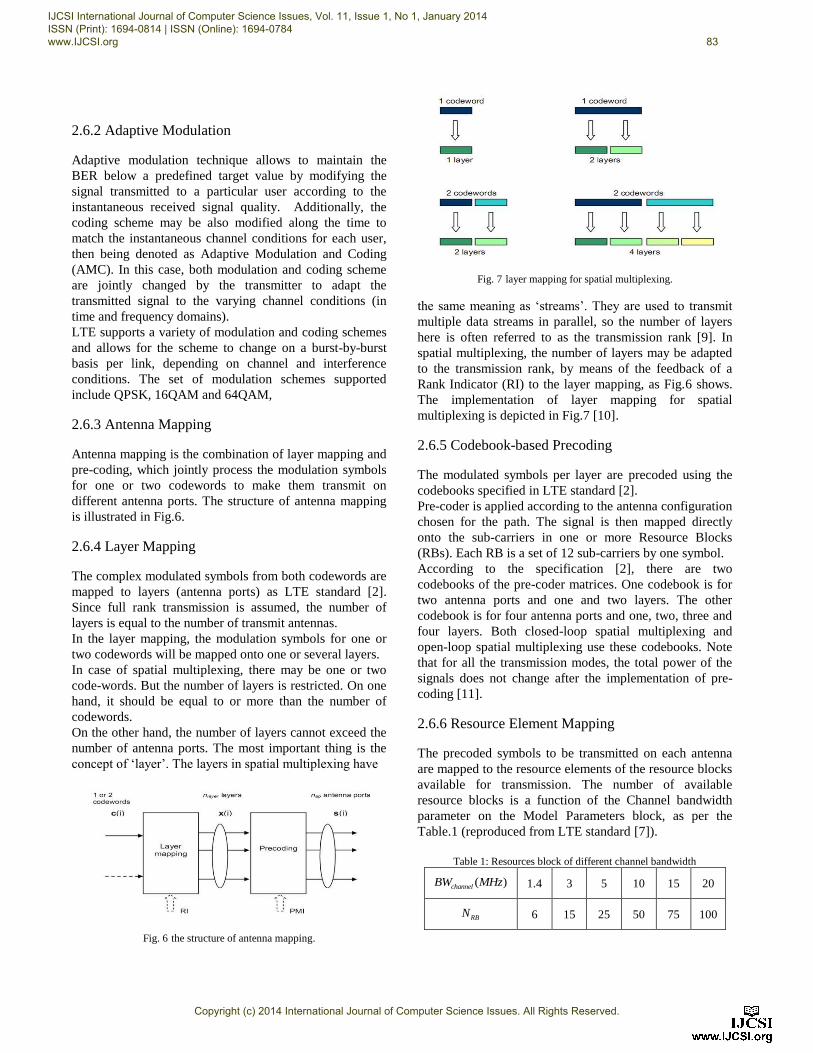
2.4 Turbo Coding
The turbo encoder is used to encode the data rate 1/3
coding rate.
The scheme of turbo encoder is a Parallel Concatenated
Convolutional Code (PCCC) with two 8-state constituent
encoders and one turbo code internal interleaver. The
structure of turbo encoder is illustrated in Fig. 4 [4].
The transfer function of the 8-state constituent code for the
PCCC is:
1
0
( )( ) 1,
( )
g DG D
g D
(1)
Where
2 3
0( ) 1g D D D
3
1( ) 1g D D D
The output from the turbo encoder consists of three
information bit streams with the same length k :
Systematic bit stream: ( kx , k = 0,1, … , 1k )
Parity bit stream: ( kz , k = 0,1, … , 1k )
Interleaved parity bit stream: ( kz , k = 0, 1, …. , 1k )
Fig. 4 Structure of rate 1/3 turbo encoder (dotted lines apply for trellis
termination only).
2.5 Rate Matching
The main task of the Rate matching is to extract the exact
set of bits to be transmitted within a given subframe from
the encoded bits. The sub-block interleaving is
implemented by creation of the circular buffer and the
actual bit selection using UE categories parameters of LTE
standard [2].
2.6 PDSCH Processing
A physical channel corresponds to a set of time-frequency
resources used for transmission of a particular transport
channel. Each transport channel maps to a corresponding
physical channel as shown in the Fig.5 [2]. The PDSCH is
the main physical channel used for unicast data
transmission. We use spatial multiplexed codebook-based
transmission, and, as a result, the downlink physical
channel processing includes:
2.6.1 Scrambling
The transport channel encoded bits are scrambled by a bit-
level scrambling sequence. The scrambling sequence
depends on the physical layer cell identity to ensure
interference randomization between cells.
Fig. 5 Overview of physical channel processing.
IJCSI International Journal of Computer Science Issues, Vol. 11, Issue 1, No 1, January 2014 ISSN (Print): 1694-0814 | ISSN (Online): 1694-0784 www.IJCSI.org 82
Copyright (c) 2014 International Journal of Computer Science Issues. All Rights Reserved.
2.6.2 Adaptive Modulation
Adaptive modulation technique allows to maintain the
BER below a predefined target value by modifying the
signal transmitted to a particular user according to the
instantaneous received signal quality. Additionally, the
coding scheme may be also modified along the time to
match the instantaneous channel conditions for each user,
then being denoted as Adaptive Modulation and Coding
(AMC). In this case, both modulation and coding scheme
are jointly changed by the transmitter to adapt the
transmitted signal to the varying channel conditions (in
time and frequency domains).
LTE supports a variety of modulation and coding schemes
and allows for the scheme to change on a burst-by-burst
basis per link, depending on channel and interference
conditions. The set of modulation schemes supported
include QPSK, 16QAM and 64QAM,
2.6.3 Antenna Mapping
Antenna mapping is the combination of layer mapping and
pre-coding, which jointly process the modulation symbols
for one or two codewords to make them transmit on
different antenna ports. The structure of antenna mapping
is illustrated in Fig.6.
2.6.4 Layer Mapping
The complex modulated symbols from both codewords are
mapped to layers (antenna ports) as LTE standard [2].
Since full rank transmission is assumed, the number of
layers is equal to the number of transmit antennas.
In the layer mapping, the modulation symbols for one or
two codewords will be mapped onto one or several layers.
In case of spatial multiplexing, there may be one or two
code-words. But the number of layers is restricted. On one
hand, it should be equal to or more than the number of
codewords.
On the other hand, the number of layers cannot exceed the
number of antenna ports. The most important thing is the
concept of ‘layer’. The layers in spatial multiplexing have
Fig. 6 the structure of antenna mapping.
Fig. 7 layer mapping for spatial multiplexing.
the same meaning as ‘streams’. They are used to transmit
multiple data streams in parallel, so the number of layers
here is often referred to as the transmission rank [9]. In
spatial multiplexing, the number of layers may be adapted
to the transmission rank, by means of the feedback of a
Rank Indicator (RI) to the layer mapping, as Fig.6 shows.
The implementation of layer mapping for spatial
multiplexing is depicted in Fig.7 [10].
2.6.5 Codebook-based Precoding
The modulated symbols per layer are precoded using the
codebooks specified in LTE standard [2].
Pre-coder is applied according to the antenna configuration
chosen for the path. The signal is then mapped directly
onto the sub-carriers in one or more Resource Blocks
(RBs). Each RB is a set of 12 sub-carriers by one symbol.
According to the specification [2], there are two
codebooks of the pre-coder matrices. One codebook is for
two antenna ports and one and two layers. The other
codebook is for four antenna ports and one, two, three and
four layers. Both closed-loop spatial multiplexing and
open-loop spatial multiplexing use these codebooks. Note
that for all the transmission modes, the total power of the
signals does not change after the implementation of pre-
coding [11].
2.6.6 Resource Element Mapping
The precoded symbols to be transmitted on each antenna
are mapped to the resource elements of the resource blocks
available for transmission. The number of available
resource blocks is a function of the Channel bandwidth
parameter on the Model Parameters block, as per the
Table.1 (reproduced from LTE standard [7]).
Table 1: Resources block of different channel bandwidth
( )channelBW MHz 1.4 3 5 10 15 20
RBN 6 15 25 50 75 100
IJCSI International Journal of Computer Science Issues, Vol. 11, Issue 1, No 1, January 2014 ISSN (Print): 1694-0814 | ISSN (Online): 1694-0784 www.IJCSI.org 83
Copyright (c) 2014 International Journal of Computer Science Issues. All Rights Reserved.
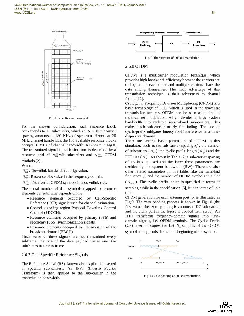
Fig. 8 Downlink resource grid.
For the chosen configuration, each resource block
corresponds to 12 subcarriers, which at 15 KHz subcarrier
spacing amounts to 180 KHz of spectrum. Hence, at 20
MHz channel bandwidth, the 100 available resource blocks
occupy 18 MHz of channel bandwidth. As shown in Fig.8,
The transmitted signal in each slot time is described by a
resource grid of DL RB
RB SCN N subcarriers and DL
symbN OFDM
symbols [2].
Where DL
RBN : Downlink bandwidth configuration. RB
SCN : Resource block size in the frequency domain. DL
symbN : Number of OFDM symbols in a downlink slot.
The actual number of data symbols mapped to resource
elements per subframe depends on the
Resource elements occupied by Cell-Specific
Reference (CSR) signals used for channel estimation.
Control signaling region Physical Downlink Control
Channel (PDCCH).
Resource elements occupied by primary (PSS) and
secondary (SSS) synchronization signals.
Resource elements occupied by transmission of the
broadcast channel (PBCH).
Since some of these signals are not transmitted every
subframe, the size of the data payload varies over the
subframes in a radio frame.
2.6.7 Cell-Specific Reference Signals
The Reference Signal (RS), known also as pilot is inserted
in specific sub-carriers. An IFFT (Inverse Fourier
Transform) is then applied to the sub-carrier in the
transmission bandwidth.
Fig. 9 The structure of OFDM modulation.
2.6.8 OFDM
OFDM is a multicarrier modulation technique, which
provides high bandwidth efficiency because the carriers are
orthogonal to each other and multiple carriers share the
data among themselves. The main advantage of this
transmission technique is their robustness to channel
fading [12].
Orthogonal Frequency Division Multiplexing (OFDM) is a
basic technology of LTE, which is used in the downlink
transmission scheme. OFDM can be seen as a kind of
multi-carrier modulation, which divides a large system
bandwidth into multiple narrowband sub-carriers. This
makes each sub-carrier nearly flat fading. The use of
cyclic-prefix mitigates intersymbol interference in a time-
dispersive channel.
There are several basic parameters of OFDM in this
simulator, such as the sub-carrier spacing f , the number
of subcarriers (scN ), the cyclic prefix length ( cpN ) and the
FFT size ( N ). As shown in Table. 2, a sub-carrier spacing
of 15 kHz is used and the latter three parameters are
decided by the system bandwidth (BW). There are also
other related parameters in this table, like the sampling
frequency sf and the number of OFDM symbols in a slot
( symbN ). The cyclic prefix length is specified in terms of
samples, while in the specification [5], it is in terms of unit
time.
OFDM generation for each antenna port for is illustrated in
Fig.9. The zero padding process is shown in Fig.10 (the
first value after zero padding is an unused DC-sub-carrier
and the blank part in the figure is padded with zeros). An
IFFT transforms frequency-domain signals into time-
domain signals, i.e. OFDM symbols. The Cyclic Prefix
(CP) insertion copies the last cpN samples of the OFDM
symbol and appends them at the beginning of the symbol.
Fig. 10 Zero padding of OFDM modulation.
IJCSI International Journal of Computer Science Issues, Vol. 11, Issue 1, No 1, January 2014 ISSN (Print): 1694-0814 | ISSN (Online): 1694-0784 www.IJCSI.org 84
Copyright (c) 2014 International Journal of Computer Science Issues. All Rights Reserved.
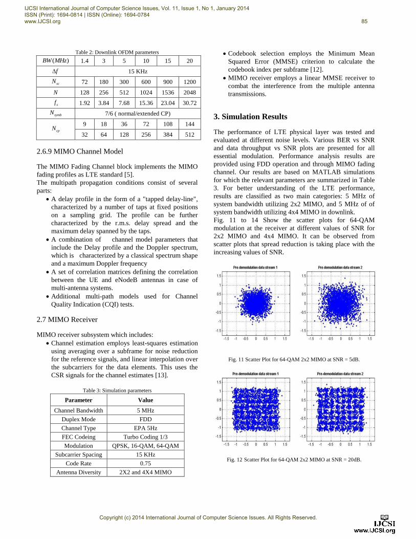
Table 2: Downlink OFDM parameters
( )BW MHz 1.4 3 5 10 15 20
f 15 KHz
scN 72 180 300 600 900 1200
N 128 256 512 1024 1536 2048
sf 1.92 3.84 7.68 15.36 23.04 30.72
symbN 7/6 ( normal/extended CP)
cpN 9 18 36 72 108 144
32 64 128 256 384 512
2.6.9 MIMO Channel Model
The MIMO Fading Channel block implements the MIMO
fading profiles as LTE standard [5].
The multipath propagation conditions consist of several
parts:
A delay profile in the form of a "tapped delay-line",
characterized by a number of taps at fixed positions
on a sampling grid. The profile can be further
characterized by the r.m.s. delay spread and the
maximum delay spanned by the taps.
A combination of channel model parameters that
include the Delay profile and the Doppler spectrum,
which is characterized by a classical spectrum shape
and a maximum Doppler frequency
A set of correlation matrices defining the correlation
between the UE and eNodeB antennas in case of
multi-antenna systems.
Additional multi-path models used for Channel
Quality Indication (CQI) tests.
2.7 MIMO Receiver
MIMO receiver subsystem which includes:
Channel estimation employs least-squares estimation
using averaging over a subframe for noise reduction
for the reference signals, and linear interpolation over
the subcarriers for the data elements. This uses the
CSR signals for the channel estimates [13].
Table 3: Simulation parameters
Parameter Value
Channel Bandwidth 5 MHz
Duplex Mode FDD
Channel Type EPA 5Hz
FEC Codeing Turbo Coding 1/3
Modulation QPSK, 16-QAM, 64-QAM
Subcarrier Spacing 15 KHz
Code Rate 0.75
Antenna Diversity 2X2 and 4X4 MIMO
Codebook selection employs the Minimum Mean
Squared Error (MMSE) criterion to calculate the
codebook index per subframe [12].
MIMO receiver employs a linear MMSE receiver to
combat the interference from the multiple antenna
transmissions.
3. Simulation Results
The performance of LTE physical layer was tested and
evaluated at different noise levels. Various BER vs SNR
and data throughput vs SNR plots are presented for all
essential modulation. Performance analysis results are
provided using FDD operation and through MIMO fading
channel. Our results are based on MATLAB simulations
for which the relevant parameters are summarized in Table
3. For better understanding of the LTE performance,
results are classified as two main categories: 5 MHz of
system bandwidth utilizing 2x2 MIMO, and 5 MHz of of
system bandwidth utilizing 4x4 MIMO in downlink.
Fig. 11 to 14 Show the scatter plots for 64-QAM
modulation at the receiver at different values of SNR for
2x2 MIMO and 4x4 MIMO. It can be observed from
scatter plots that spread reduction is taking place with the
increasing values of SNR.
Fig. 11 Scatter Plot for 64-QAM 2x2 MIMO at SNR = 5dB.
Fig. 12 Scatter Plot for 64-QAM 2x2 MIMO at SNR = 20dB.
IJCSI International Journal of Computer Science Issues, Vol. 11, Issue 1, No 1, January 2014 ISSN (Print): 1694-0814 | ISSN (Online): 1694-0784 www.IJCSI.org 85
Copyright (c) 2014 International Journal of Computer Science Issues. All Rights Reserved.
Fig. 13 Scatter Plot for 64-QAM 4x4 MIMO at SNR = 5dB.
Fig. 14 Scatter Plot for 64-QAM 4x4 MIMO at SNR = 20dB.
3.1 LTE CBER
Fig.15 and 16 illustrate the codeword bit error rate
(CBER) values for two codeword for codebook index 1 as
specification of 3GPP release 10 using QPSK, 16-QAM
and 64-QAM. The two MIMO techniques (2X2 and 4X4)
are applied. It can be noticed that the lower modulation
scheme provides better performance with less SNR,
furthermore, The selection of the AMC mode is made in
such a way that guarantees a BER below a given target
BER. As the modulation is 64-QAM. A relatively high
SNR is observed for the good BER performance. In fact,
The BER of 10-3
is achieved with 28 dB of SNR in 4x4
MIMO configuration however the same value of BER is
achieved with only 24 dB in the 2x2 diversity scheme. So
an SNR gain of 4 dB is clearly observed for 2x2 diversity
scheme.
Fig. 15 CBER vs SNR for 2x2 MIMO.
Fig. 16 CBER vs SNR for 4x4 MIMO..
3.2 Data Throughput
The data throughput results of the two MIMO schemes are
presented in the Fig.17 and 18 for FDD operation based on
mentioned parameters in Table.3, the data throughput of
2x2 MIMO configuration is shown in Fig.17. It can
observed that as the SNR increase the data throughput
increase and it reaches its maximum at almost 24 dB SNR
as in CBER, the high order modulation is behind the high
SNR required to achieve the maximum capacity of 30
Mbps in the PDSCH channel.
The data throughput of 4x4 MIMO configurations is
shown in Fig.18. It can achieve the maximum data
throughput of 74 Mbps at SNR 28 dB. When the eNB uses
the bandwidth of 5 MHz for transferring data to the user
equipment in the PDSCH channel by using 64-QAM and
code rate 0.75.
IJCSI International Journal of Computer Science Issues, Vol. 11, Issue 1, No 1, January 2014 ISSN (Print): 1694-0814 | ISSN (Online): 1694-0784 www.IJCSI.org 86
Copyright (c) 2014 International Journal of Computer Science Issues. All Rights Reserved.
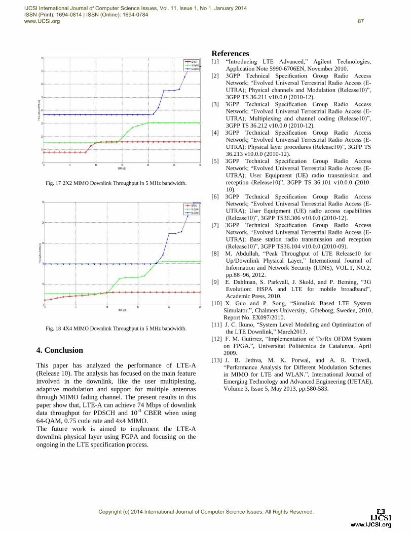
Fig. 17 2X2 MIMO Downlink Throughput in 5 MHz bandwidth.
Fig. 18 4X4 MIMO Downlink Throughput in 5 MHz bandwidth.
4. Conclusion
This paper has analyzed the performance of LTE-A
(Release 10). The analysis has focused on the main feature
involved in the downlink, like the user multiplexing,
adaptive modulation and support for multiple antennas
through MIMO fading channel. The present results in this
paper show that, LTE-A can achieve 74 Mbps of downlink
data throughput for PDSCH and 10-3
CBER when using
64-QAM, 0.75 code rate and 4x4 MIMO.
The future work is aimed to implement the LTE-A
downlink physical layer using FGPA and focusing on the
ongoing in the LTE specification process.
References [1] “Introducing LTE Advanced,” Agilent Technologies,
Application Note 5990-6706EN, November 2010.
[2] 3GPP Technical Specification Group Radio Access
Network; “Evolved Universal Terrestrial Radio Access (E-
UTRA); Physical channels and Modulation (Release10)”,
3GPP TS 36.211 v10.0.0 (2010-12).
[3] 3GPP Technical Specification Group Radio Access
Network; “Evolved Universal Terrestrial Radio Access (E-
UTRA); Multiplexing and channel coding (Release10)”,
3GPP TS 36.212 v10.0.0 (2010-12).
[4] 3GPP Technical Specification Group Radio Access
Network; “Evolved Universal Terrestrial Radio Access (E-
UTRA); Physical layer procedures (Release10)”, 3GPP TS
36.213 v10.0.0 (2010-12).
[5] 3GPP Technical Specification Group Radio Access
Network; “Evolved Universal Terrestrial Radio Access (E-
UTRA); User Equipment (UE) radio transmission and
reception (Release10)”, 3GPP TS 36.101 v10.0.0 (2010-
10).
[6] 3GPP Technical Specification Group Radio Access
Network; “Evolved Universal Terrestrial Radio Access (E-
UTRA); User Equipment (UE) radio access capabilities
(Release10)”, 3GPP TS36.306 v10.0.0 (2010-12).
[7] 3GPP Technical Specification Group Radio Access
Network, “Evolved Universal Terrestrial Radio Access (E-
UTRA); Base station radio transmission and reception
(Release10)”, 3GPP TS36.104 v10.0.0 (2010-09).
[8] M. Abdullah, “Peak Throughput of LTE Release10 for
Up/Downlink Physical Layer,” International Journal of
Information and Network Security (IJINS), VOL.1, NO.2,
pp.88–96, 2012.
[9] E. Dahlman, S. Parkvall, J. Skold, and P. Beming, “3G
Evolution: HSPA and LTE for mobile broadband”,
Academic Press, 2010.
[10] X. Guo and P. Song, “Simulink Based LTE System
Simulator.”, Chalmers University, Göteborg, Sweden, 2010,
Report No. EX097/2010.
[11] J. C. Ikuno, “System Level Modeling and Optimization of
the LTE Downlink,” March2013.
[12] F. M. Gutirrez, “Implementation of Tx/Rx OFDM System
on FPGA.”, Universitat Politècnica de Catalunya, April
2009.
[13] J. B. Jethva, M. K. Porwal, and A. R. Trivedi,
“Performance Analysis for Different Modulation Schemes
in MIMO for LTE and WLAN.”, International Journal of
Emerging Technology and Advanced Engineering (IJETAE),
Volume 3, Issue 5, May 2013, pp:580-583.
IJCSI International Journal of Computer Science Issues, Vol. 11, Issue 1, No 1, January 2014 ISSN (Print): 1694-0814 | ISSN (Online): 1694-0784 www.IJCSI.org 87
Copyright (c) 2014 International Journal of Computer Science Issues. All Rights Reserved.