Embed Size (px)
Citation preview

Performance and Computational Complexity Assessment of High-Efficiency Video Encoders
A project proposal on
Performance and Computational Complexity Assessment of High-Efficiency Video Encoders
Under the guidance of Dr. K. R. Rao
For the fulfillment of the course Multimedia Processing (EE5359)Spring 2016
Submitted by
Manu Rajendra Sheelvant
UTA ID: 1001112728
Email id: [email protected]
Department of Electrical Engineering
The University of Texas at Arlington
MANU RAJENDRA SHEELVANT 1 1001112728

Performance and Computational Complexity Assessment of High-Efficiency Video Encoders
Table of ContentsList of Acronyms and Abbreviations……………………………………………………………...3Abstract…………………………………………………………………………………................5
1. Objective of the Project……………………………………………………………………………62. H.265/High Efficiency Video Coding(HEVC)...………………………………………………….7
2.1 Introduction……………………………………………………………………..................72.2 Encoder and Decoder…………………………………………………………...................72.3 Features of HEVC……………………………………………………………....................8
2.3.1 Coding tree units and coding tree block (CTB) structure…………………....……92.3.2 Coding Units (CUs) and coding blocks (CBs)…………………………………...102.3.3 Prediction units and prediction blocks (PBs)…………………………………….112.3.4 Transform Units(TUs) and transform blocks…………………………..………...112.3.5 Motion Vector Signaling……………………………………………....................112.3.6 Motion Compensation………………………………………………....................112.3.7 Intra-picture prediction………………………………………………………...…122.3.8 Quantization Control…………………………………………………………..…132.3.9 Entropy Coding………………………………………………………………...…132.3.10 In-loop de-blocking filtering…………………………………………………...…132.3.11Sample Adaptive Offset (SAO)………………………..………………………...…14
3. Recent works on complex analysis…………………………………………………………...…...153.1 Reference Code Analysis…………………………………………………………...……..153.2 Reported Runtime…………………………………………………………………...…….153.3 Time-Stamp Counter………………………………………………………………………153.4 Energy Consumption Analysis and Estimation……………………………………………163.5 Software Profilers………………………………………………………………………….16
4. HEV Encoders……………………………………………………………………………………..17 5. Experimental Setup………………………………………………………………………………..18 6. References…………………………………………………………………………………………19
MANU RAJENDRA SHEELVANT 2 1001112728

Performance and Computational Complexity Assessment of High-Efficiency Video Encoders
List of Acronyms and Abbreviations
ALF: Adaptive Loop Filter.
AVC: Advanced Video Coding.
CABAC: Context Adaptive Binary Arithmetic Coding
CTB: Coding Tree Block.
CTU: Coding Tree Unit.
CU: Coding Unit.
CB: Coding Block.
DBF: De-blocking Filter.
DCT: Discrete Cosine Transform.
DST: Discrete Sine Transform.
DVFS: Dynamic Voltage and Frequency Scaling.
GBD-PSNR: Generalized Bjontegaard Delta – PSNR.
HEVC: High Efficiency Video Coding.
HEVC-DM: HEVC Direct Mode.
HEVC-LM: HEVC Linear Mode.
HM: HEVC Test Model.
HP: Hierarchical Prediction.
JCT: Joint Collaborative Team.
JCT-VC: Joint Collaborative Team on Video Coding.
JM: H.264 Test Model.
JPEG: Joint Photographic Experts Group.
LCU: Largest Coding Units.
MV: Motion Vector.
MC: Motion Compensation.
ME: Motion Estimation.
MPEG: Motion Picture Experts Group.
NSQT: Non-Square Quadtree.
PC: Prediction Chunking.
PU: Prediction Unit.
PB: Prediction Block.
PSNR: Power Signal-to-Noise Ratio.
MANU RAJENDRA SHEELVANT 3 1001112728

Performance and Computational Complexity Assessment of High-Efficiency Video Encoders
QP: Quantization Parameter.
RDO: Rate Distortion Optimization.
RDTSC: Read Time Stamp Counter.
RQT: Residual Quadtree.
SAO: Sample Adaptive Offset.
TB: Transform Block.
TSC: Time Stamp Counter.
TU: Transform Unit.
VCEG: Video Coding Experts Group.
MANU RAJENDRA SHEELVANT 4 1001112728

Performance and Computational Complexity Assessment of High-Efficiency Video Encoders
Abstract
This project presents a performance evaluation study of coding efficiency versus computational
complexity for the forthcoming High Efficiency Video Coding (HEVC) [1] standard. A thorough
experimental investigation was carried out to identify the tools that most affect the encoding
efficiency and computational complexity of the HEVC encoder. A set of 16 different encoding
configurations was created to investigate the impact of each tool, varying the encoding parameter set
and comparing the results with a baseline encoder. This paper shows that, even though the
computational complexity increases monotonically from the baseline to the most complex
configuration, the encoding efficiency saturates at some point [2]. Moreover, the results of this paper
provide relevant information for implementation of complexity-constrained encoders by taking into
account the tradeoff between complexity and coding efficiency. It is shown that low-complexity
encoding configurations, defined by careful selection of coding tools, achieve coding efficiency
comparable to that of high-complexity configurations.
MANU RAJENDRA SHEELVANT 5 1001112728

Performance and Computational Complexity Assessment of High-Efficiency Video Encoders
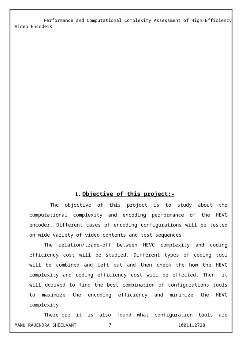
1. Objective of this project:- The objective of this project is to study about the computational complexity and encoding
performance of the HEVC encoder. Different cases of encoding configurations will be tested on wide
variety of video contents and test sequences.
The relation/trade-off between HEVC complexity and coding efficiency cost will be studied.
Different types of coding tool will be combined and left out and then check the how the HEVC
complexity and coding efficiency cost will be effected. Then, it will derived to find the best
combination of configurations tools to maximize the encoding efficiency and minimize the HEVC
complexity.
Therefore it is also found what configuration tools are helpful for high HEVC encoding
efficiency and find what configuration tools have the minimum effect on HEVC encoding efficiency.
The simulation will be conducted using HM 16.4 software [3], with different video sequences
[4], configuration tools like Search Range, Hadamard ME, Fast Merge Decision, Deblocking Filter,
Sample Adaptive Offset, Adaptive Loop filter, Transform Skipping, and other tools.
MANU RAJENDRA SHEELVANT 6 1001112728
Performance and Computational Complexity Assessment of High-Efficiency Video Encoders
2. H.265 / High Efficiency Video Coding
2.1 Introduction
High Efficiency Video Coding (HEVC) is an international standard for video compression developed
by a working group of ISO/IEC MPEG (Moving Picture Experts Group) and ITU-T VCEG (Video
Coding Experts Group). The main goal of HEVC standard is to significantly improve compression
performance compared to existing standards (such as H.264/Advanced Video Coding [7]) in the
range of 50% bit rate reduction at similar visual quality [1].
HEVC is designed to address existing applications of H.264/MPEG-4 AVC and to focus on two key
issues: increased video resolution and increased use of parallel processing architectures [1]. It
primarily targets consumer applications as pixel formats are limited to 4:2:0 8-bit and 4:2:0 10-bit.
The next revision of the standard, will enable new use-cases with the support of additional pixel
formats such as 4:2:2 and 4:4:4 and bit depth higher than 10-bit [8], embedded bit-stream scalability
and 3D video [9].
2.2 Encoder and Decoder in HEVC
Source video, consisting of a sequence of video frames, is encoded or compressed by a video
encoder to create a compressed video bit stream. The compressed bit stream is stored or transmitted.
A video decoder decompresses the bit stream to create a sequence of decoded frames [10].
The video encoder performs the following steps:
Partitioning each picture into multiple units
Predicting each unit using inter or intra prediction, and subtracting the prediction from the unit
Transforming and quantizing the residual (the difference between the original picture unit and the
prediction)
Entropy encoding transform output, prediction information, mode information and headers
The video decoder performs the following steps:
Entropy decoding and extracting the elements of the coded sequence
Rescaling and inverting the transform stage
Predicting each unit and adding the prediction to the output of the inverse transform
Reconstructing a decoded video image
MANU RAJENDRA SHEELVANT 7 1001112728

Performance and Computational Complexity Assessment of High-Efficiency Video Encoders
The Figure 1 represents the block diagram of HEVC CODEC [10] :
Figure 1: Block Diagram of HEVC CODEC [10].
2.3 Features of HEVC
The video coding layer of HEVC employs the same hybrid approach (inter-/intra-picture prediction
and 2-D transform coding) used in all video compression standards. Figure. 1 depicts the block
diagram of a hybrid video encoder, which can create a bitstream conforming to the HEVC standard.
Figure.5 shows the HEVC decoder block diagram. An encoding algorithm producing an HEVC
compliant bitstream would typically proceed as follows. Each picture is split into block-shaped
regions, with the exact block partitioning being conveyed to the decoder. The first picture of a video
sequence (and the first picture at each clean random access point in a video sequence) is coded using
only intra-picture prediction (that uses prediction of data spatially from region-to-region within the
same picture, but has no dependence on other pictures). For all remaining pictures of a sequence or
between random access points, inter-picture temporally predictive coding modes are typically used
for most blocks.
The encoding process for inter-picture prediction consists of choosing motion data
comprising the selected reference picture and Motion Vector (MV) to be applied for predicting the
samples of each block. The encoder and decoder generate identical inter-picture prediction signals by
applying motion compensation (MC) using the MV and mode decision data, which are transmitted as
side information. The residual signal of the intra- or inter-picture prediction, which is the difference
between the original block and its prediction, is transformed by a linear spatial transform. The
transform coefficients are then scaled, quantized, entropy coded, and transmitted together with the
prediction information. The encoder duplicates the decoder processing loop (see gray-shaded boxes
MANU RAJENDRA SHEELVANT 8 1001112728

Performance and Computational Complexity Assessment of High-Efficiency Video Encoders
in Figure.4) such that both will generate identical predictions for subsequent data. Therefore, the
quantized transform coefficients are constructed by inverse scaling and are then inverse transformed
to duplicate the decoded approximation of the residual signal. The residual is then added to the
prediction, and the result of that addition may then be fed into one or two loop filters to smooth out
artifacts induced by block-wise processing and quantization.
The final picture representation (that is a duplicate of the output of the decoder) is stored in a
decoded picture buffer to be used for the prediction of subsequent pictures. In general, the order of
encoding or decoding processing of pictures often differs from the order in which they arrive from
the source; necessitating a distinction between the decoding order (i.e., bitstream order) and the
output order (i.e., display order) for a decoder. Video material to be encoded by HEVC is generally
expected to be input as progressive scan imagery (either due to the source video originating in that
format or resulting from de-interlacing prior to encoding). No explicit coding features are present in
the HEVC design to support the use of interlaced scanning, as interlaced scanning is no longer used
for displays and is becoming substantially less common for distribution. However, a metadata syntax
has been provided in HEVC to allow an encoder to indicate that interlace-scanned video has been
sent by coding each field (i.e., the even or odd numbered lines of each video frame) of interlaced
video as a separate picture or that it has been sent by coding each interlaced frame as an HEVC
coded picture. This provides an efficient method of coding interlaced video without burdening
decoders with a need to support a special decoding process for it. In the following, the various
features involved in hybrid video coding using HEVC are highlighted as follows.
2.3.1 Coding tree units and coding tree block (CTB) structure: The core of the coding layer in
previous standards was the macroblock, containing a 16×16 block of luma samples and, in the usual
case of 4:2:0 color sampling, two corresponding 8×8 blocks of croma samples; whereas the
analogous structure in HEVC is the coding tree unit (CTU), which has a size selected by the encoder
and can be larger than a traditional macroblock. The CTU consists of a luma CTB and the
corresponding croma CTBs and syntax elements. The size L×L of a luma CTB can be chosen as L =
16, 32, or 64 samples, with the larger sizes typically enabling better compression. HEVC then
supports a partitioning of the CTBs into smaller blocks using a tree structure and quad tree-like
signalling. The partitioning of CTBs into CBs ranging from 64*64 down to 8*8 is shown in
Figure.2.
MANU RAJENDRA SHEELVANT 9 1001112728

Performance and Computational Complexity Assessment of High-Efficiency Video Encoders
Figure 2: 64*64 CTBs split into CBs [13]
2.3.2 Coding units (CUs) and coding blocks (CBs): The quad tree syntax of the CTU specifies the
size and positions of its luma and croma CBs. The root of the quadtree is associated with the CTU.
Hence, the size of the luma CTB is the largest supported size for a luma CB. The splitting of a CTU
into luma and croma CBs is signaled jointly. One luma CB and ordinarily two croma CBs, together
with associated syntax, form a coding unit (CU) as shown in Figure.3. A CTB may contain only one
CU or may be split to form multiple CUs, and each CU has an associated partitioning into prediction
units (PUs) and a tree of transform units (TUs).
Figure 3: CUs split into CBs [13]
MANU RAJENDRA SHEELVANT 10 1001112728

Performance and Computational Complexity Assessment of High-Efficiency Video Encoders
2.3.3 Prediction units and prediction blocks (PBs): The decision whether to code a picture area
using interpicture or intrapicture prediction is made at the CU level. A PU partitioning structure has
its root at the CU level. Depending on the basic prediction-type decision, the luma and croma CBs
can then be further split in size and predicted from luma and croma prediction blocks (PBs) as shown
in Figure. 4. HEVC supports variable PB sizes from 64×64 down to 4×4 samples.
Figure 4: Partitioning of Prediction Blocks from Coding Blocks [13]
2.3.4 TUs and transform blocks: The prediction residual is coded using block transforms. A TU
tree structure has its root at the CU level. The luma CB residual may be identical to the luma
transform block (TB) or may be further split into smaller luma TBs as shown in Figure.5. The same
applies to the Croma TBs. Integer basis functions similar to those of a discrete cosine transform
(DCT) are defined for the square TB sizes 4×4, 8×8, 16×16, and 32×32. For the 4×4 transform of
luma intrapicture prediction residuals, an integer transform derived from a form of discrete sine
transform (DST) is alternatively specified.
Figure 5: Partitioning of Transform Blocks from Coding Blocks [13]
2.3.5 Motion vector signalling: Advanced motion vector prediction (AMVP) is used, including
derivation of several most probable candidates based on data from adjacent PBs and the reference
picture. A merge mode for MV coding can also be used, allowing the inheritance of MVs from
temporally or spatially neighboring PBs. Moreover, compared to H.264/MPEG-4 AVC [7],
improved skipped and direct motion inference is also specified.
2.3.6 Motion compensation: Quarter-sample precision is used for the MVs and 7-tap or 8-tap filters
are used for interpolation of fractional-sample positions (compared to six-tap filtering of half-sample
MANU RAJENDRA SHEELVANT 11 1001112728

Performance and Computational Complexity Assessment of High-Efficiency Video Encoders
positions followed by linear interpolation for quarter-sample positions in H.264/MPEG-4 AVC).
Similar to H.264/MPEG-4 AVC, multiple reference pictures are used as shown in Figure.6. For each
PB, either one or two motion vectors can be transmitted, resulting either in uni-predictive or bi-
predictive coding, respectively. As in H.264/MPEG-4 AVC, a scaling and offset operation may be
applied to the prediction signal(s) in a manner known as weighted prediction.
Figure 6: Quadtree structure used for MVs [13]
Figure 7: Concept of multi-frame motion-compensated prediction [13]
2.3.7 Intra-picture prediction: The decoded boundary samples of adjacent blocks are used as
reference data for spatial prediction in regions where inter-picture prediction is not performed. Intra
picture prediction supports 33 directional modes (compared to eight such modes in H.264/MPEG-4
AVC[7]), plus planar (surface fitting) and DC (flat) prediction modes. The selected intra-picture
prediction modes are encoded by deriving most probable modes (e.g., prediction directions) based on
those of previously decoded neighboring PBs.
MANU RAJENDRA SHEELVANT 12 1001112728
Performance and Computational Complexity Assessment of High-Efficiency Video Encoders
Figure 8: Directional Prediction Modes in H.264 [13]
Figure 9: Modes and directional orientations for intra picture prediction in HEVC [13]
2.3.8 Quantization control: As in H.264/MPEG-4 AVC, uniform reconstruction quantization
(URQ) is used in HEVC, with quantization scaling matrices supported for the various transform
block sizes.
2.3.9 Entropy coding: Context adaptive binary arithmetic coding (CABAC) is used for entropy
coding. This is similar to the CABAC scheme in H.264/MPEG-4 AVC, but has undergone several
improvements to improve its throughput speed (especially for parallel-processing architectures) and
its compression performance, and to reduce its context memory requirements.
2.3.10 In-loop de-blocking filtering: A de-blocking filter similar to the one used in H.264/MPEG-4
AVC [7] is operated within the inter-picture prediction loop. However, the design is simplified in
regard to its decision-making and filtering processes, and is made more friendly to parallel
processing.
MANU RAJENDRA SHEELVANT 13 1001112728

Performance and Computational Complexity Assessment of High-Efficiency Video Encoders
2.3.11 Sample adaptive offset (SAO): A nonlinear amplitude mapping is introduced within the
inter-picture prediction loop after the de-blocking filter. Its goal is to better reconstruct the original
signal amplitudes by using a look-up table that is described by a few additional parameters that can
be determined by histogram analysis at the encoder side.
MANU RAJENDRA SHEELVANT 14 1001112728

Performance and Computational Complexity Assessment of High-Efficiency Video Encoders
3. Recent work on Complexity AnalysisSeveral works have been published in the last few years, addressing the problem of
complexity analysis of video encoders [18] and decoders [23]. Generally, these works evaluate the
relationship between compression efficiency and complexity, mainly focusing on computational
complexity (processing time or instruction-level profiling). Processing time has been largely used to
measure computational complexity of video coding systems [18], but other approaches such as
theoretical analysis [19], direct analysis of reference code [21], and power consumption evaluation
[18], have also been frequently applied to measure complexity.
3.1 Reference Code Analysis: Lehtoranta and Hamalainen [21] analyzed the reference code of an
MPEG-4 encoder, evaluating its processing modules by counting their equivalent number of RISC
like instructions. The overall complexity of the MPEG-4 encoder was then compared to that of
H.263 and H.264/AVC encoders. Chang-Guo et al. [32] also analyzed the C code implementation of
an MPEG decoder using the number of basic processor instructions to estimate the computational
complexity measured in MOPS. The code size and complex implementation structures of the
reference software in modern video encoders/decoders make this kind of direct analysis of computer
code extremely difficult and inaccurate, which encourages the use of other methods and tools.
3.2 Reported Runtime Other works measure the computational complexity simply based on the
encoding and decoding report generated by the reference software of each standard, which generally
includes processing time information. As an example of this approach, Xiang et al. [33] report on a
method called generalized Bjøntegaard delta PSNR (GBD-PSNR) for evaluating coding efficiency
that takes into consideration the bit rate, the image distortion, and the processing time. The
computational complexity for each of the main H.264/AVC encoding modules is also theoretically
estimated and experimentally evaluated in [19], considering all coding modes possibilities. The
experimental results in [19] and [33] are based on the runtime reported by the reference software.
Although this type of information provides a rough indication about encoding complexity, to support
valid conclusions an accurate analysis is necessary using a controlled test environment and specific
tools.
3.3 Time Stamp Counter The time stamp counter (TSC) is a register present in all x86 processors
since Pentium, which counts the number of clock cycles from the last reset to the current instant. The
instruction read time stamp counter (RDTSC) has been used in some works, such as [29] and [30], to
estimate the computational complexity of each module and also that of the overall encoder/decoder.
Until recently, the use of TSC has been accepted as an excellent way of getting high-resolution, low-
overhead processing time information. However, the use of TSC is not accurate in modern
MANU RAJENDRA SHEELVANT 15 1001112728

Performance and Computational Complexity Assessment of High-Efficiency Video Encoders
processors that support out-of-order execution, since the RDTSC instruction may be executed earlier
or later than expected, resulting in a wrong clock cycle count.
3.4 Energy Consumption Analysis and Estimation In [18], the average power dissipation was
measured using the PTscalar thermal and power microarchitecture simulator [34]. In [24], the
complexity of the AVS encoder is analyzed taking into consideration the processing time in terms of
clock cycles for the Pentium platforms. In this case, the energy consumption is estimated by the Intel
Application Energy Toolkit. In [28], actual power dissipation data are extracted through direct
measurements in a dynamic voltage and frequency scaling (DVFS) ARM processor employed for
energy efficient video decoding.
3.5 Software Profilers Profiling tools have been used to automate the complexity analysis of video
codecs and generate more reliable results. In [22], the Atomium profiler was used to measure the
computational complexity of the main coding functions in the H.264/AVC video codec.
Comparisons between H.264/AVC and MPEG-4 Part 2 are also presented. Saponara et al. [23]
analyzed 18 possible configurations of the H.264/AVC encoder, comparing all of them in terms of
complexity versus PSNR in order to identify the best ones. The Atomium profiler was also used to
obtain the complexity data by executing the instrumented code with representative test stimuli.
The software profilers provide an accurate and easy-to-use method for measuring complexity
in video encoders. Each individual module can be evaluated separately, and batch processing can be
used to run several tests in a row, using different predefined configurations.
MANU RAJENDRA SHEELVANT 16 1001112728

Performance and Computational Complexity Assessment of High-Efficiency Video Encoders
4. HEV EncodersThe reference software used in the development phase, called HEVC test model (HM),
provides a common framework for research and development [4]. Six mandatory configurations for
normalized experiments have been proposed by JCT-VC [37]. These are combinations of two
possible complexity or efficiency settings, defined as high efficiency 10 (HE10) and Main, 1 and
three basic coding or access settings, named as Intra Only, Random Access, and Low Delay. The
HE10 setting is used for high coding efficiency (and high complexity), whereas Main defines a
coding configuration with low computational complexity, which does not provide the best coding
efficiency. The Intra Only mode uses no temporal prediction, Random Access allows the use of
future frames as reference in temporal prediction, and Low Delay uses only previous frames as
reference.
One of the most important features introduced by HEVC is the use of quadtree-based frame
partitioning structures. In HEVC, each video slice is divided into a number of square blocks of equal
size called treeblocks [or largest coding units (LCUs)], which are used as the roots of each coding
quadtree (or coding tree). Each leaf of the coding tree is called a coding unit (CU) and its dimensions
can vary from 8 × 8 to 64 × 64 pixels (or up to the treeblock size), depending on the tree depth. For
each CU, intra- or inter-frame prediction can be independently applied. Each CU can be divided into
two or four prediction units (PU), which are predicted separately. When transform coding of the
prediction residue is used, each CU is assumed to be the root of another quadtree-based structure
called residual quadtree (RQT). Each leaf of the RQT is known as a transform unit (TU), which can
take on sizes from 4×4 to 32 ×32 pixels (or up to the CU size), including non-square formats (NSQT)
such as 4 × 16, 16 × 4, 8 × 32 and 32 × 8 for inter-predicted areas.
HE10 encoder configurations allow the use of asymmetric PUs in a CU (e.g., 32 × 8 PU and
32 × 24 PU into a single 32 × 32 CU), known as asymmetric motion partitions (AMP), and
nonsquare TUs (4×16, 16×4, 8×32 and 32×8), known as nonsquare transforms (NSQT), for inter-
predicted areas. On the other hand, the Main encoder configurations limit PUs to symmetric formats
and TUs to square sizes.
The encoding mode decision algorithm selects the best coding tree configuration, the best PU
division, and the best RQT structure based on exhaustive iterations of the ratedistortion optimization
(RDO) process, which considers every encoding possibility and compares all of them in terms of bit
rate and image quality. Therefore, both the data structures and the encoding process are responsible
for an enormous share of the overall computational complexity. A temporal analysis of
computational complexity incurred by the use of such encoding structures in HEVC and a
complexity control technique were recently presented in [38].
MANU RAJENDRA SHEELVANT 17 1001112728

Performance and Computational Complexity Assessment of High-Efficiency Video Encoders
Intra-frame prediction in HEVC is an extension of intraframe prediction in H.264/AVC,
supporting larger block sizes (from 4 × 4 to 64 × 64) and allowing more prediction directions: 16
different luma angular modes for 4 × 4 PUs, 2 luma angular modes for 64 × 64 PUs, and 33 luma
angular modes for the other PU sizes. Besides these angular modes, a DC prediction mode similar to
DC in H.264/AVC and a planar prediction mode designed to reconstruct smooth image segments
through bilinear interpolation from the PU borders may also be applied to any PU. The number of
chroma intra prediction modes was also increased to six in HEVC: direct mode (DM), linear mode
(LM), vertical (mode 0), horizontal (mode 1), DC (mode 2), and planar (mode 3). DM is used when
the texture directionality of luma and chroma is similar; LM is used when the sample intensities of
luma and chroma are highly correlated. In the first case, the same mode used for luma prediction is
used for chroma, whereas in the second case, the chroma components are predicted from
downsampled reconstructed luma values of the same PU.
Similarly to H.264/AVC, HEVC inter-frame prediction relies on block-based motion
compensation (MC). Motion estimation (ME) is based on advanced motion vector prediction, which
includes a motion vector competition scheme [39] along with a motion merge [40] technique. The
former defines a set of motion vector predictor candidates comprising motion vectors of spatially and
temporally neighboring PUs. The best motion vector predictor is selected from the set of candidates
through RD optimization. Motion merging is based on a similar principle, but in this case the motion
parameters are not explicitly transmitted. They are instead derived at the decoder based on the
prediction mode and merge mode parameters.
Transform and quantization are heavily based on H.264/AVC, even though larger block sizes
(ranging from 4×4 to 32×32) are supported. For inter-predicted PUs, a discrete cosine transform
(DCT) is applied to the prediction residue, whereas for intra-predicted PUs, the encoder can choose
between applying the DCT[20] or a mode-dependent discrete sine transform (DST)[20].
Regarding the entropy coding, the current HEVC draft supports only context-adaptive binary
arithmetic coding (CABAC), which was already used in H.264/AVC. Even though the CABAC
structure is basically the same as it was in H.264/AVC, HEVC aims at decreasing the computational
burden associated with binarization and context retrieving by reducing the number of syntax
elements to binarize and the number of contexts, and by increasing throughput by enabling parallel
processing of transform coefficients [41].
The HEVC deblocking filter (DF) is also similar to that used in H.264/AVC. However,
instead of performing deblocking at the boundaries of 4 × 4 blocks, the DF is applied to boundaries
belonging to CUs, PUs, and TUs larger than 4×4 pixels. Vertical and horizontal edges are filtered
according to a border filtering strength, which varies from 0 (no filtering) to 4 (maximum filtering
MANU RAJENDRA SHEELVANT 18 1001112728

Performance and Computational Complexity Assessment of High-Efficiency Video Encoders
strength) and also depends on the border characteristics. In addition to the DF, HEVC employs two
new filters: the sample adaptive offset (SAO) and the adaptive loop filter (ALF). SAO processes the
entire picture as a hierarchical quadtree, classifying the reconstructed pixels into different categories
and then reducing distortion by adding an offset to the pixels in each category. This classification is
performed taking into consideration the pixel intensity and edge properties. ALF is used after the DF
and the SAO to reduce the distortion between the original and the reconstructed frame caused by
lossy compression. The filtering is performed by applying a 2-D Wiener filter[9] at CU level
depending on the difference between values of samples in the original and reconstructed frames.
MANU RAJENDRA SHEELVANT 19 1001112728

Performance and Computational Complexity Assessment of High-Efficiency Video Encoders
5. Experimental SetupAs highlighted in the previous section, the HEVC encoder includes a large number of coding
tools, each one having a different contribution to the overall coding efficiency and complexity. The
operation of these tools and their functional modes are determined by encoding configuration
parameters, which may be set to several different values. The experimental study presented in this
article was carried out in two steps. Firstly, the coding tools that have stronger impact on both coding
efficiency and computational complexity were identified. To that end, the individual contribution of
each and every encoding tool to such performance metrics was experimentally evaluated. Secondly,
those tools identified in the first step and sorted according to encoding gain per complexity increase
were selected for further analysis, which consisted in evaluating the impact of each tool in a
cumulative enabling order. To conduct the experiments, a subset of 5 video sequences was selected
from the 24 sequences specified in the Common Test Conditions document from JCT-VC [37].
These sequences differ broadly from one another in terms of frame rate, bit depth, motion, and
texture characteristics as well as spatial resolution. Table 1 presents the name, frame count, frame
rate, and spatial resolution of each sequence.
The reference software used in all tests was the HEVC Model—version 16.9 (HM16.9) [4] in
release mode, compiled using Microsoft Visual Studio C++ Compiler. All tests were performed on a
personal computer based on Processor Intel(R) Core(TM) i3-2330M CPU @ 2.20GHz running on
Windows(TM)10 Home 64-bit Operating system.
Test Sequence Resolution Frame Rate Total No. of Frames Pace
BQ Mall 832x480 60 601 Medium
Kirsten and Sara 1280x720 60 600 Slow
Park Scene 1920x1080 24 240 Medium
People On Street 2560x1600 30 150 Slow
Race Horses 416x240 30 300 Medium
Table 1:- Test sequences used to implement the analysis.
MANU RAJENDRA SHEELVANT 20 1001112728

Performance and Computational Complexity Assessment of High-Efficiency Video Encoders
Figure 10:- BQMall_832x480_60.yuv
Figure 11:- KristenAndSara_1280x720_60.yuv (Zoom 1:2)
MANU RAJENDRA SHEELVANT 21 1001112728

Performance and Computational Complexity Assessment of High-Efficiency Video Encoders
Figure 12:- ParkScene_1920x1080_24.yuv (Zoom 1:4)
Figure 13:- PeopleOnStreet_2560x1600_30_crop.yuv (Zoom 1:4)
MANU RAJENDRA SHEELVANT 22 1001112728

Performance and Computational Complexity Assessment of High-Efficiency Video Encoders
Figure 14 :- RaceHorses_416x240_30.yuv
MANU RAJENDRA SHEELVANT 23 1001112728

Performance and Computational Complexity Assessment of High-Efficiency Video Encoders
6 . Comparison Metrics
6.1 Peak Signal to Noise RatioPeak signal-to-noise ratio (PSNR) [35] [36] is an expression for the ratio between the
maximum possible value (power) of a signal and the power of distorting noise that affects the quality
of its representation. Because many signals have a very wide dynamic range (ratio between the
largest and smallest possible values of a changeable quantity), the PSNR is usually expressed in
terms of the logarithmic decibel scale.
PSNR is most commonly used to measure the quality of reconstruction of lossy compression
codecs. The signal in this case is the original data, and the noise is the error introduced by
compression. When comparing compression codecs, PSNR is an approximation to human perception
of reconstruction quality. Although a higher PSNR generally indicates that the reconstruction is of
higher quality, in some cases it may not. One has to be extremely careful with the range of validity of
this metric; it is only conclusively valid when it is used to compare results from the same codec (or
codec type) and same content.
PSNR is defined via the mean squared error (MSE). Given a noise-free m x n monochrome
image I and its noisy approximation K, MSE is defined as:
The PSNR is defined as
Here, MAXI is the maximum possible pixel value of the image.
For test sequences in 4:2:0 color format, PSNR is computed as a weighted average of
luminance ( Y) and chrominance ( U,V ) components [14] as given below:
MANU RAJENDRA SHEELVANT 24 1001112728

Performance and Computational Complexity Assessment of High-Efficiency Video Encoders
6.2 Bjontegaard Delta Bit-rate (BD-BR) and Bjontegaard Delta PSNR (BD-PSNR)
To objectively evaluate the coding efficiency of video codecs, Bjontegaard Delta PSNR (BD-
PSNR) was proposed. Based on the rate-distortion (R-D) curve fitting, BD-PSNR provides a good
evaluation of the R-D performance [37] [38].
BD metrics allow to compute the average gain in PSNR or the average per cent saving in Bit-
rate between two rate-distortion curves. However, BD-PSNR has a critical drawback: It does not
take the coding complexity into account [37].
6.3 Implementation Complexity
The computational time for various configuration profiles in HM-16.9 software will be
compared and this serves as an indication of implementation complexity.
MANU RAJENDRA SHEELVANT 25 1001112728

Performance and Computational Complexity Assessment of High-Efficiency Video Encoders
7. Implementation
7.1 Configuration profiles used for comparison Test sequences in YUV format are encoded using the Random access profile of HM-16.9 and are compared using different configuration parameters used.
7.2 Parameters modified F - Number of frames to be encoded Fr - Frame rate Wdt - Width of the video sequence Hgt - Height of the video sequence Profile - encoder_randomaccess _main.
Command line parameters for using HM-16.9 encoder:
TAppEncoder [-h] [-c config.cfg] [--parameter=value]
Options:-h Prints parameter usage-c Defines configuration file to use. Multiple configuration files may be used.--parameter=value Assigns value to a given parameter.
7.3 Sample command line parameters for HM-16. 9 C:\Users\mann\Desktop\Spr_2016\Multimedia_Signal_Processing\HM_16.9\bin\vc2015\x64\
Release>TAppEncoder.exe –c C:\Users\mann\Desktop\Spr_2016\Multimedia_Signal_Processing\HM_16.9\
cfg\encoder_randomaccess_main.cfg –i C:\Users\mann\Desktop\Spr_2016\Multimedia_Signal_Processing\
HM_16.9\cfg\BQMall_832x480_60.yuv –hgt 480 –wdt 832 –f 300 –fr 60
7.4 Test Configurations used:
The Test configurations and outputs are being submitted on the another file in .xls format because it cannot
be portrayed in the .doc format.
8. Implementation Results:8.1 People On The Street:-
MANU RAJENDRA SHEELVANT 26 1001112728

Performance and Computational Complexity Assessment of High-Efficiency Video Encoders
1 2 3 4 5 6 7 8 9 10 11 12 13 14 1534.9
35
35.1
35.2
35.3
35.4
35.5
35.6
People on Street(YUV-PSNR)
Test Configurations
YUV-
PSN
R (in
dB)
Figure 14:- YUV-PSNR for People On Street for different configurations.
1 2 3 4 5 6 7 8 9 10 11 12 13 14 158050
8100
8150
8200
8250
8300
8350
8400
8450
People on Street(Bit Rate)
Test Configurations
Bit R
ate
(in b
ps)
Figure 15:- Bit Rate for People On Street for different configurations.
MANU RAJENDRA SHEELVANT 27 1001112728

Performance and Computational Complexity Assessment of High-Efficiency Video Encoders
1 2 3 4 5 6 7 8 9 10 11 12 13 14 150
5000
10000
15000
20000
25000
30000
35000
40000
People on Street- Time Taken(Complexity)
Test Configurations
Tim
e Ta
ken
(in se
cs)
Figure 16:- Encoding Complexity for People On Street for different configurations.
8.2 Race Horses:-
1 2 3 4 5 6 7 8 9 10 11 12 13 14 1532.5
32.55
32.6
32.65
32.7
32.75
32.8
32.85
32.9
32.95
Race Horses (YUV-PSNR)
Test Configurations
YUV-
PSNR
(in
bB)
Figure 17:- YUV-PSNR for Race Horses for different configurations.
MANU RAJENDRA SHEELVANT 28 1001112728

Performance and Computational Complexity Assessment of High-Efficiency Video Encoders
1 2 3 4 5 6 7 8 9 10 11 12 13 14 15300
302
304
306
308
310
312
314
316
318
Race Horses (Bit Rate)
Test Configurations
Bit R
ate
(in b
ps)
Figure 18:- Bit Rate for Race Horses for different configurations.
1 2 3 4 5 6 7 8 9 10 11 12 13 14 150
200
400
600
800
1000
1200
1400
Race Horses-Time Taken (Complexity)
Test Configurations
Tim
e Ta
ken
(in se
cs)
Figure 19:- Encoding Complexity for Race Horses for different configurations.
MANU RAJENDRA SHEELVANT 29 1001112728

Performance and Computational Complexity Assessment of High-Efficiency Video Encoders
9. References:[1] G.J. Sullivan et al, “Overview of the High Efficiency Video Coding (HEVC) Standard”, IEEE
Transactions on Circuits and Systems for Video Technology(CSVT), Vol. 22, No. 12, pp. 1649-
1668, Dec. 2012.
[2] G. Correa et al, “Performance and computational complexity assessment of high efficiency video
encoders”, IEEE Trans. CSVT, vol. 22, pp.1899-1909, Dec. 2012.
[3] Video test sequences - https://media.xiph.org/video/derf/.
[4] HM 16.9 software - https://hevc.hhi.fraunhofer.de/trac/hevc/milestone/HM-16.9.
[5] I.E.G. Richardson, “Video Codec Design: Developing Image and Video Compression Systems”,
Wiley, 2002.
[6] B. Bross et al, “High Efficiency Video Coding (HEVC) Text Specification Draft 10”, Document
JCTVC-L1003, ITU-T/ISO/IEC Joint Collaborative Team on Video Coding (JCT-VC),Mar.2013.
[7] D. Marpe et al, “The H.264/MPEG4 advanced video coding standard and its applications”, IEEE
Communications Magazine, Vol. 44, pp. 134-143, Aug. 2006.
[8] HEVC white paper-Ateme: http://www.ateme.com/an-introduction-to-uhdtv-and-hevc
[9] G.J. Sullivan et al, “Standardized Extensions of High Efficiency Video Coding (HEVC)”, IEEE
Journal of selected topics in Signal Processing, Vol. 7, No. 6, pp. 1001-1016, Dec. 2013.
[10] HEVC tutorial by I.E.G. Richardson: http://www.vcodex.com/h265.html
[11] C. Fogg, “Suggested figures for the HEVC specification”, ITU-T / ISO-IEC Document: JCTVC
J0292r1, July 2012.
[12] T. Wiegand et al, “Overview of the H.264/AVC Video Coding Standard”, IEEE Transactions on
Circuits and Systems for Video Technology, Vol. 13, No. 7, pp. 560-576, Jul. 2003.
[13] U.S.M. Dayananda, “Study and Performance comparison of HEVC and H.264 video codecs”
M.S. Thesis, EE Dept., UTA, Arlington, TX, Dec. 2011 available on
http://www.uta.edu/faculty/krrao/dip/Courses/EE5359/index_tem.html
[14] M. Wein, “ High Efficiency Video Coding: Coding Tools and Specification”, Springer, 2014.
MANU RAJENDRA SHEELVANT 30 1001112728

Performance and Computational Complexity Assessment of High-Efficiency Video Encoders
[15] T. Vermeir, “Use cases and requirements for lossless and screen content coding”, JCTVC-
M0172, 13th JCT-VC meeting, Incheon, KR, Apr. 2013.
[16] J. Sole et al, “Requirements for wireless display applications”, JCTVC-M0315, 13th JCT-VC
meeting, Incheon, KR, Apr. 2013.
[17] A. Gabriellini et al, “Combined Intra-Prediction for High-Efficiency Video Coding”, IEEE
Journal of selected topics in Signal Processing. Vol. 5, no. 7, pp. 1282-1289, Nov. 2011.
[18] L. Younghoon, K. Jungsoo, and K. Chong-Min, “Energy-aware video encoding for image
quality improvement in battery-operated surveillance camera,” IEEE Trans. Very Large Scale
Integration (VLSI) Syst., vol. 20, no. 2, pp. 310–318, Feb. 2012.
[19] W. Kim, J. You, and J. Jeong, “Complexity control strategy for real-time H.264/AVC encoder,”
IEEE Trans. Consumer Electron., vol. 56, no. 2, pp. 1137–1143, May 2010.
[20] D. N. Kwon, P. F. Driessen, A. Basso, and P. Agathoklis, “Performance and computational
complexity optimization in configurable hybrid video coding system,” IEEE Trans. Circuits Syst.
Video Technol., vol. 16, no. 1, pp. 31–42, Jan. 2006.
[21] O. Lehtoranta and T. D. Hamalainen, “Complexity analysis of spatially scalable MPEG-4
encoder,” in Proc. Int. Symp. System-on-Chip, 2003, pp. 57–60.
[22] J. Ostermann, et al., “Video coding with H.264/AVC: Tools, performance, and complexity,”
IEEE Circuits Syst. Mag., vol. 4, no. 1, pp. 7–28, Jan.–Mar. 2004.
[23] S. Saponara, K. Denolf, G. Lafruit, C. Blanch, and J. Bormans, “Performance and complexity
co-evaluation of the advanced video coding standard for cost-effective multimedia communications,”
EURASIP J. Appl. Signal Process., vol. 2004, pp. 220–235, Jan. 2004.
[24] P. Li, Y. Chen, and W. Ji, “Rate-distortion-complexity analysis on AVS encoder,” presented at
the 11th Pacific Rim Conf. Multimedia, Shanghai, China, 2011.
[25] A. Hallapuro, V. Lappalainen, and T. D. Hamalainen, “Performance analysis of low bit rate
H.26L video encoder,” presented at the Proc. IEEE Int. Conf. Acoustics, Speech, and Signal
Processing, vol. 2, pp. 1129-1132, May 2001.
MANU RAJENDRA SHEELVANT 31 1001112728

Performance and Computational Complexity Assessment of High-Efficiency Video Encoders
[26] M. Horowitz, A. Joch, F. Kossentini, and A. Hallapuro, “H.264/AVC baseline profile decoder
complexity analysis,” IEEE Trans. Circuits Syst. Video Technol., vol. 13, no. 7, pp. 704–716, Jul.
2003.
[27] L. Szu-Wei and C. C. J. Kuo, “Complexity modeling of spatial and temporal compensations in
H.264/AVC decoding,” IEEE Trans. Circuits Syst. Video Technol., vol. 20, no. 5, pp. 706–720, May
2010.
[28] M. Zhan, H. Hao, and W. Yao, “On complexity modeling of H.264/AVC video decoding and its
application for energy efficient decoding,” IEEE Trans. Multimedia, vol. 13, no. 6, pp. 1240–1255,
Dec. 2011.
[29] V. Lappalainen, A. Hallapuro, and T. D. Hamalainen, “Complexity of optimized H.26L video
decoder implementation,” IEEE Trans. Circuits Syst. Video Technol., vol. 13, no. 7, pp. 717–725,
Jul. 2003.
[30] On Software Complexity, JCTVC-G757, ISO/IEC-JCT1/SC29/WG11, Geneva, Switzerland,
2011.
[31] HM Decoder Complexity Assessment on ARM, JCTVC-G262, ISO/IECJCT1/SC29/WG11,
Geneva, Switzerland, 2011.
[32] Z. Chang-Guo et al., “MPEG video decoding with the UltraSPARC visual instruction set,” in
Proc. Compcon ’95: Technol. Inform. Superhighway Dig. Papers, 1995, pp. 470–477.
[33] L. Xiang, M. Wien, and J. R. Ohm, “Rate-complexity-distortion optimization for hybrid video
coding,” IEEE Trans. Circuits Syst. Video Technol., vol. 21, no. 7, pp. 957–970, Jul. 2011.
[34] PTscalar V1.0 [Online]. Available: http://eda.ee.ucla.edu/PTscalar/
[35] OProfile: A System Profiler for Linux [Online]. Available: http://oprofile.sourceforge.net/news/
[36] PAPI Performance Application Programming Interface [Online]. Available:
http://icl.cs.utk.edu/papi/
[37] Common Test Conditions and Software Reference Configurations, JCTVC-I1100, ISO/IEC-
JCT1/SC29/WG11, Geneva, Switzerland, 2012.
[38] G. Correa, P. Assuncao, L. Agostini, and L. A. da Silva Cruz, “Complexity control of high
efficiency video encoders for power-constrained devices,” IEEE Trans. Consumer Electron., vol. 57,
no. 4, pp. 1866– 1874, Nov. 2011. MANU RAJENDRA SHEELVANT 32 1001112728

Performance and Computational Complexity Assessment of High-Efficiency Video Encoders
[39] G. Laroche, J. Jung, and B. Pesquet-Popescu, “RD optimized coding for motion vector predictor
selection,” IEEE Trans. Circuits Syst. Video Technol., vol. 18, no. 9, pp. 1247–1257, Sep. 2008.
[40] S. Oudin et al., “Block merging for quadtree-based video coding,” in Proc. IEEE Int. Conf.
Multimedia Expo, pp. 1–6, July 2011.
[41] V. Sze and M. Budagavi, “Parallelization of CABAC transform coefficient coding for HEVC,”
in Proc. PCS, pp. 509–512, 2012.
MANU RAJENDRA SHEELVANT 33 1001112728


![Reducing Complexity of HEVC: A Deep Learning Approach · 2015, several machine learning approaches [7]–[11] have been proposedto predict the CU partition toward HEVC complexity](https://img.pdfslide.net/doc/110x75/5f51623cc0ee1b3b6a6c0700/reducing-complexity-of-hevc-a-deep-learning-approach-2015-several-machine-learning.jpg)