Embed Size (px)
Citation preview

Performance and durability of photovoltaic
backsheets and comparison to outdoor
performance
William Gambogi
DuPont Photovoltaic Solutions, Wilmington, DE, 19803
Atlas NIST Workshop on PV Materials Durability,
Gaithersburg, MD
November 13, 2013
1
© DuPont 2013

2
• Review Weathering Stresses
• Materials in Photovoltaic Module Constructions
• Fielded Module Studies
• Comparison of UV and DH Accelerated Results and
Fielded Module Performance
• Accelerated Test Protocols
• UV Test Protocols for Backsheet to Address
Qualification Shortcomings
• Conclusions
Outline
© DuPont 2013

Stresses for PV Modules and Materials
glass
front encapsulant
tabbed silicon cell strings back encapsulant
backsheet
junction box
with adhesive
Mechanical
Abrasion
High Temperature
Transmitted
and Reflected
UV
Thermal
Cycling
Moisture Ingress
(Humidity &
Condensation)
Atmospheric
Chemicals
Direct UV
Internal Electric Fields
• Combined stresses operate throughout greater than 25 year module lifetime
• Backsheet is the first line of defense in all geographic locations and installations
• UV durability has been under-tested and its effects in the field under-estimated
Mechanical
Load
© DuPont 2013

Cell metallization pastes
Solamet®
C
A
Front Sheet Materials
Teflon® films
Films for
backsheets
Tedlar®
Module Encapsulant
Resins
Elvax®
B
F
Module Encapsulant Sheets
DuPont™ PV5200
DuPont™ PV5300
Thin Film Substrates
Kapton®
polyimide
films
D
B
Rynite®
E
Engineering
resins & components
Crystalline
silicon Thin film
Material Combinations Create Unique Interactions
Unique Opportunity for Deep Understanding of Performance © DuPont 2013
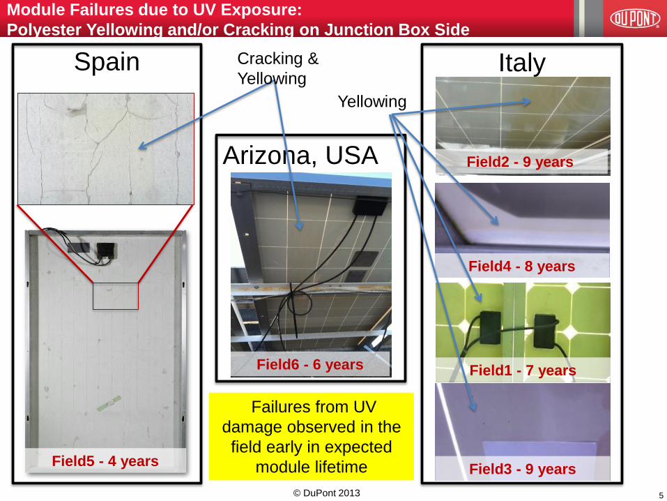
Field5 - 4 years
Italy
Field1 - 7 years
Field4 - 8 years
Field3 - 9 years
Field2 - 9 years Arizona, USA
Field6 - 6 years
Module Failures due to UV Exposure:
Polyester Yellowing and/or Cracking on Junction Box Side
Spain Cracking &
Yellowing
Yellowing
5
Failures from UV
damage observed in the
field early in expected
module lifetime
© DuPont 2013

Fielded Module Example
6
JB
• Modules were removed from a commercial MW plant after 5 years for cracking
and delamination on the backsheet along the rear tabbing ribbons and 9% loss
of power.
• The IR analysis identified outer layer as polyester.
• Thermal image shows localized heating at cell contacts.
Cracking on the outer polyester layer of backsheet
Cracking of the backsheet is
likely due to indirect UV
exposure. Backsheet testing to
reflected light from albedo can
identify instability in the outdoor
environment.
© DuPont 2013
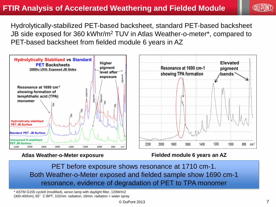
FTIR Analysis of Accelerated Weathering and Fielded Module
Hydrolytically-stabilized PET-based backsheet, standard PET-based backsheet
JB side exposed for 360 kWhr/m2 TUV in Atlas Weather-o-meter*, compared to
PET-based backsheet from fielded module 6 years in AZ
* ASTM G155 cycle9 (modified), xenon lamp with daylight filter, 120W/m2
(300-400nm), 65°C BPT, 102min. radiation, 18min. radiation + water spray
7
PET before exposure shows resonance at 1710 cm-1.
Both Weather-o-Meter exposed and fielded sample show 1690 cm-1
resonance, evidence of degradation of PET to TPA monomer
Atlas Weather-o-Meter exposure Fielded module 6 years an AZ
Elevated
pigment
bands
© DuPont 2013
© DuPont 2013
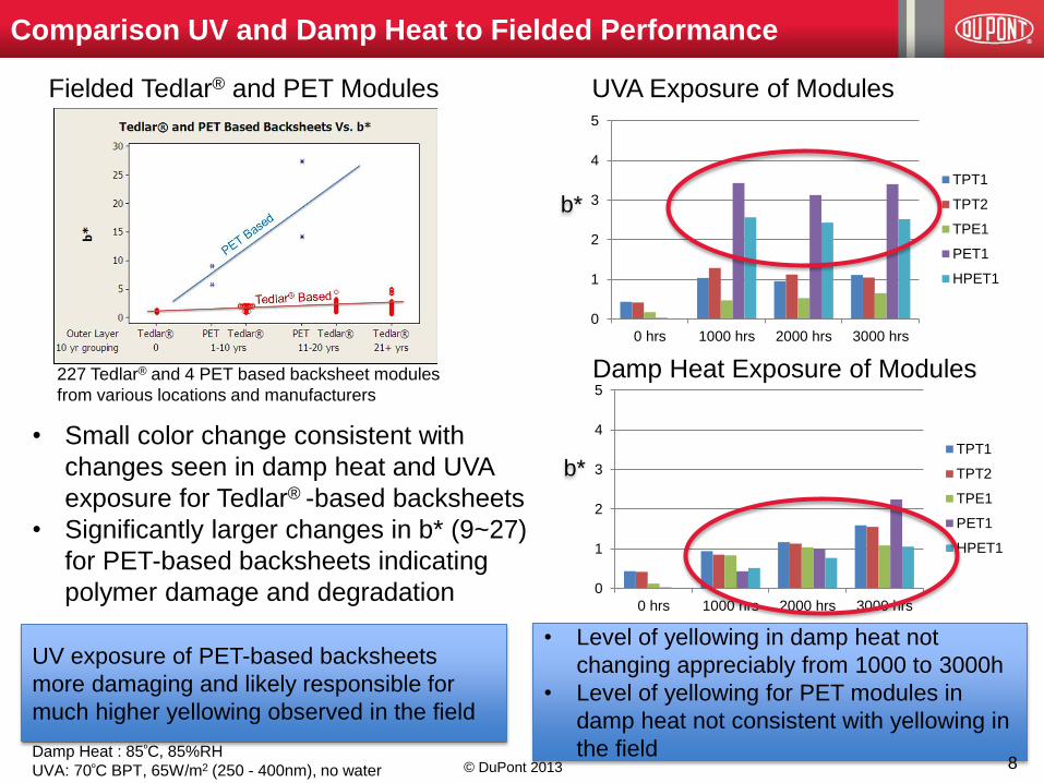
Comparison UV and Damp Heat to Fielded Performance
• Small color change consistent with
changes seen in damp heat and UVA
exposure for Tedlar® -based backsheets
• Significantly larger changes in b* (9~27)
for PET-based backsheets indicating
polymer damage and degradation
Damp Heat Exposure of Modules
UVA Exposure of Modules
Damp Heat : 85ºC, 85%RH
UVA: 70ºC BPT, 65W/m2 (250 - 400nm), no water
0
1
2
3
4
5
0 hrs 1000 hrs 2000 hrs 3000 hrs
TPT1
TPT2
TPE1
PET1
HPET1
0
1
2
3
4
5
0 hrs 1000 hrs 2000 hrs 3000 hrs
TPT1
TPT2
TPE1
PET1
HPET1
227 Tedlar® and 4 PET based backsheet modules
from various locations and manufacturers
Fielded Tedlar® and PET Modules
UV exposure of PET-based backsheets
more damaging and likely responsible for
much higher yellowing observed in the field
• Level of yellowing in damp heat not
changing appreciably from 1000 to 3000h
• Level of yellowing for PET modules in
damp heat not consistent with yellowing in
the field 8
b*
b*

© DuPont 2013
Comparison of Properties - Damp Heat and Fielded Exposure
9
Mechanicals
• Loss in mechanical properties in damp heat (>1000h) due to hydrolysis of PET core layers (not Tedlar®)
No loss in mechanical properties for humid environment – Miyako Island, Japan • Mechanical loss at 2000h and 3000h much greater than observed in the field
• Fielded modules from different environments obtained from DuPont (USA), AIST (Japan) and JRC (Italy)

© DuPont 2013
Potential Loss of
Electrical Insulation
0
0.2
0.4
0.6
0.8
1
1.2
2.5 3 3.5 4 4.5 5 5.5
dW
/ d
(Lo
g M
)
Log M
Outer Layer 1
Outer Layer 2
Inner Layer 1
Inner Layer 2
10
PET Layer
Tested Mn Mw Mw/Mn
Outer Layer 1 3,340 13,000 3.90
Outer Layer 2 3,000 13,700 4.56
Inner Layer 1 7,400 15,800 2.14
Inner Layer 2 7,300 15,600 2.15
Analyses of PET Layers
Molecular Weight Analysis • Outer PET layer shows likely drop and
broadening of Mw
• Inner PET layer no changes were observed
• These changes are most likely due to
stresses during service (UV, moisture, etc.)
Mechanical Properties • Compared to a standard PET, the inner
layer of PET dropped 60% in tensile (MD)
and 40% in elongation properties
• Outer layer lost all mechanical properties
Outer PET degraded – Mw changes and loss
of mechanical properties
Inner PET degraded – loss of mechanical
properties with no Mw changes
Field
Location
Time in
service
Backsheet
Construction
(thickness/mm color)
Mount
Type b*
Module 6 Japan 9 yrs PET(12mm, Clear?)
/ PET(50mm, White)
Open
Rack 5.77
Analysis of Fielded PET Module
Inner
PET
Layer
Control
PET % Retention
Tensile (Mpa) 127.50 207.00 61.59
Elongation (%) 71.14 150.00 47.43 **Could not measure air side - no mechanical integrity
**Modules 4, 5 and 6 are all from the same manufacturer.

11
Front side yellowing observed in: 5 different countries (Belgium, Spain,
USA, Israel and Germany)
5 different module manufacturers
Modules less than 5 years in the field
Module Failures due to UV Exposure: 1s PVDF Front Side Yellowing
Failures from UV damage observed in the
field early in expected module lifetime
© DuPont 2013

Fielded Module Example
12
• Modules removed from a commercial MW power plant after 2 years for
severe yellowing and loss of ~4% power.
• Destructive analysis determined yellowing of inner polyethylene layer and
associated adhesive layers in the PVDF/PET/PET/PE backsheet structure.
• UV absorbance of the EVA lower than expected resulting in higher UV
exposure of the inner layer of the backsheet
Discoloration in the inner layer of a PV module backsheet
Testing of the stability of the
inner layer to UV exposure
would have identified the
instability and avoided damage
© DuPont 2013
© DuPont 2013
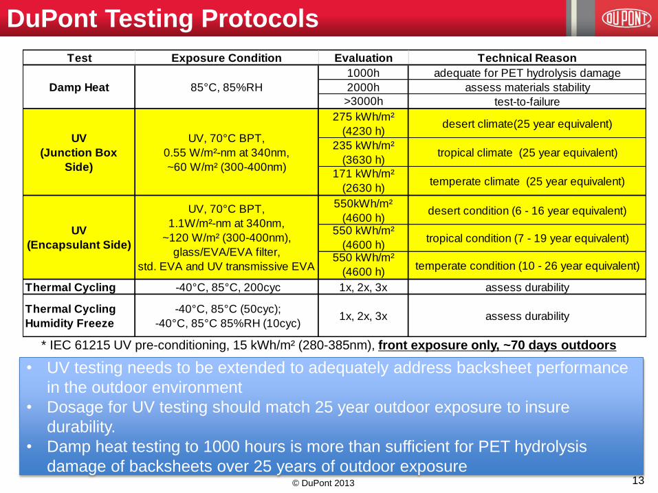
DuPont Testing Protocols
Test Exposure Condition Evaluation Technical Reason
1000h adequate for PET hydrolysis damage
2000h assess materials stability
>3000h test-to-failure
275 kWh/m²
(4230 h)desert climate(25 year equivalent)
235 kWh/m²
(3630 h)tropical climate (25 year equivalent)
171 kWh/m²
(2630 h)temperate climate (25 year equivalent)
550kWh/m²
(4600 h)desert condition (6 - 16 year equivalent)
550 kWh/m²
(4600 h)tropical condition (7 - 19 year equivalent)
550 kWh/m²
(4600 h)temperate condition (10 - 26 year equivalent)
Thermal Cycling -40°C, 85°C, 200cyc 1x, 2x, 3x assess durability
1x, 2x, 3x assess durability
UV, 70°C BPT,
0.55 W/m²-nm at 340nm,
~60 W/m² (300-400nm)
Damp Heat
UV
(Junction Box
Side)
85°C, 85%RH
-40°C, 85°C (50cyc);
-40°C, 85°C 85%RH (10cyc)
Thermal Cycling
Humidity Freeze
UV
(Encapsulant Side)
UV, 70°C BPT,
1.1W/m²-nm at 340nm,
~120 W/m² (300-400nm),
glass/EVA/EVA filter,
std. EVA and UV transmissive EVA
• UV testing needs to be extended to adequately address backsheet performance
in the outdoor environment
• Dosage for UV testing should match 25 year outdoor exposure to insure
durability.
• Damp heat testing to 1000 hours is more than sufficient for PET hydrolysis
damage of backsheets over 25 years of outdoor exposure
* IEC 61215 UV pre-conditioning, 15 kWh/m² (280-385nm), front exposure only, ~70 days outdoors
13

14
Need for Backsheet UV Testing
• Durability issues related to the backsheet are observed and
documented in fielded modules (cracking, yellowing,
delamination)
• We propose to add backsheet UV exposure to current
industry standard (currently little or no UV exposure in
qualification standards) consistent with the service
environment
• Polymeric component testing of UV stability established in
ASTM standards and used in other industries Testing designed for easy adoption and implementation using
existing equipment, methodology, and duration less than six
months
Key properties and acceptance criteria consistent with industry
protocols and field experience
Module testing limited by equipment, exposure time and
established test methodology
© DuPont 2013

1. UV Junction Box side exposure: Xenon (daylight) or UVA
fluorescent exposure, 70C BPT, 275 kWh/m2 TUV, ~25y desert
exposure**)
1. Test free-standing backsheet
2. UV Encapsulant side exposure: Xenon (daylight) exposure,
70C BPT, 550 kWh/m2 TUV, ~6y desert exposure)
1. Test laminate and free-standing backsheet
2. UV exposure through glass/2EVA/FEP filter
3. Test using standard and UV transmissive EVA
*** Assumes UVT EVA transmits >320nm and std EVA transmits at >370nm
UV Durability Test Conditions for PV Backsheet
Desert Tropical Temperate
Annual UV Exposure (kWh/m2)* 92 79 57
25 year UV Exposure (kWh/m2) 2300 1975 1425
25 year JB-side Exposure (kWh/m2)** 276 237 171
Equivalent JB-side exposure @275 kWh/m2 (years) 25 29 40
Equivalent E-side exposure @550 kWh/m2 (years) 6 7 10
Equivalent UVT E-side exposure @550 kWh/m2 (years) 16 19 26
* Total UV exposure (300-400 nm), reference: Atlas
** Assumes 12% albedo
© DuPont 2013

Impact on Power Impact on Safety Acceptance Criteria Justification
Mechanical
Visual Appearance
Indicates materials
degradation and associated
loss in key protective
properties
Indicates materials degradation
and associated loss in key
properties
no cracking, flaking, bubbling
or failure of adhesive bonds
consistent with
IEC61215
Tensile Strength
brittleness/cracking of the
backsheet leads to accelerated
corrosion of the electrical
contacts
lower force needed to cracking of
the backsheet and compromises
the electrical insulation
>70% retention
consistent with UL
746C criteria and
referenced in
UL1703
Elongation
brittleness/cracking of the
backsheet leads to accelerated
corrosion of the electrical
contacts
lower elongation results in
cracking of the backsheet and
compromises the electrical
insulation
>70% retention
consistent with UL
746C criteria and
referenced in
UL1703
Optical
Color Change (b*)
Yellowing indicates materials
changes that could translate to
reduced physical properties
tensile, elongation,
adhesion/delamination)
Yellowing indicates materials
changes that could translate to
reduced physical properties
tensile, elongation, adhesion)
change in b* < 2.0
consistent with
comparison of
accelerated test
and outdoor
performance
Criteria for Junction Box Side Exposure
UVA or UVX (daylight),
65W/m2 UV, BPT 70C,
275 kWh/m2, 4200h
JB side
© DuPont 2013

Impact on Power Impact on Safety Acceptance Criteria Justification
Mechanical
Visual Appearance
Indicates materials degradation
and associated loss in key
protective properties
Indicates materials degradation and
associated loss in key properties
no cracking, flaking, bubbling or
failure of adhesive bonds
consistent with
IEC61215
Interlayer Adhesion (ILA) delamination reduces electrical >70% retentionconsistent with UL
Optical
Reflectance
Lower reflectance reduces
recaptured light from interstitial
spaces at edge and between
cells
change < 20% absolute
consistent with
estimated 1% change
in power
Color Change (b*)
Yellowing indicates materials
changes that could translate to
reduced physical properties
tensile, elongation,
adhesion/delamination)
Yellowing indicates materials
changes that could translate to
reduced physical properties tensile,
elongation, adhesion)
change in b* < 2.0
consistent with
comparison of
accelerated testing
and outdoor
performance
Criteria for Encapsulant Side Exposure
UVT and
std EVA
UVX (daylight),
120 W/m2, BPT
70°C,
550 kWh/m2,
4200h UVT and
std EVA
Laminate test Backsheet test
Using UV transmissive EVA to get higher acceleration, wavelength sensitivity
and test range of commercial constructions. Mechanical retention criteria TBD.
© DuPont 2013
18
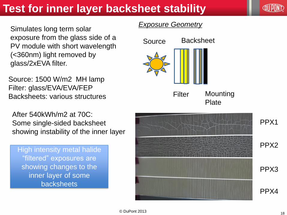
PPX1
PPX2
PPX3
PPX4
Test for inner layer backsheet stability
Source
Filter
Backsheet
Mounting
Plate
Exposure Geometry
Source: 1500 W/m2 MH lamp
Filter: glass/EVA/EVA/FEP
Backsheets: various structures
After 540kWh/m2 at 70C:
Some single-sided backsheet
showing instability of the inner layer
Simulates long term solar
exposure from the glass side of a
PV module with short wavelength
(<360nm) light removed by
glass/2xEVA filter.
High intensity metal halide
“filtered” exposures are
showing changes to the
inner layer of some
backsheets
© DuPont 2013
Accelerated Weathering and Combined Stress Testing
Xenon-Water Spray Weathering of Backsheets*
Combinations of UV/visible radiation, temperature, moisture (water spray,
condensation and/or chamber relative humidity) and thermal cycling are more
relevant to the outdoor environment
* ASTM G155 cycle9 (modified), xenon lamp with daylight filter, 120W/m2
(300-400nm), 65°C BPT, 102min. radiation, 18min. radiation + water spray
Sequential Stress (UVA vs. UVA+TC)**
** Backsheet side of module measured
UVA: 70ºC BPT, 65W/m2 (250 - 400nm), no water
TC: -40ºC, 85ºC, 200 cycles per IEC 61215
19
Cracking of inner tie layer in
PET backsheet after 1500h
outer layer exposure.
Xenon exposure only,
cracking seen at 5000 hours
PET-based backsheets show much
greater color change after UVA/TC
indicating polymer degradation and
damage
• Greater than UVA alone
• Similar to levels seen in fielded
modules
© DuPont 2013
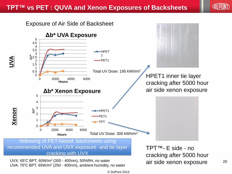
TPT™ vs PET : QUVA and Xenon Exposures of Backsheets
Exposure of Air Side of Backsheet
UV
A
Xen
on
HPET1 inner tie layer
cracking after 5000 hour
air side xenon exposure
TPT™- E side - no
cracking after 5000 hour
air side xenon exposure
Yellowing of PET-based backsheets using
recommended UVA and UVX exposure and tie layer
cracking with UVX
20 UVX: 65ºC BPT, 60W/m2 (300 - 400nm), 50%RH, no water
UVA: 70ºC BPT, 65W/m2 (250 - 400nm), ambient humidity, no water
00.5
11.5
22.5
33.5
44.5
5
0 2000 4000 6000
Δb*
Hours
Δb* UVA Exposure
HPET1
PET1
0
1
2
3
4
5
0 2000 4000 6000
Δb*
Hours
Δb* Xenon Exposure
HPET1
PET1
TPT
Total UV Dose: 195 kWh/m2
Total UV Dose: 300 kWh/m2
© DuPont 2013

Sequential Stress Testing
Sequential Stress #1: DH1000/UVA1000/TC200
Four cell mini-modules exposed to sequential stress testing to assess impact of
multiple stresses on performance and durability vs. a single stress exposure. Loss of
properties in single stress (damp heat) is observed after applying additional stresses.
Sequential Stress #2: 2x(DH1000/TC200)
21
Cracking of a single-sided PVDF
backsheet after sequential exposure
to damp heat, UV and thermal cycling
(contrast increased to highlight
cracking)
Cracking of a single-sided
PVDF backsheet after
sequential exposure to
damp heat and thermal
cycling
© DuPont 2013

22
• Current UV testing in qualification is not addressing UV stress in
backsheets. Improved UV testing is needed to better predict durability
of PV modules to stresses in the service environment
• UV test protocol developed to address encapsulant side and junction
box side exposure based on outdoor environment
• Damp heat exposure of 1000 hours is sufficient to match fielded module
degradation in even the harshest humid conditions, longer damp heat
exposure leads to degradation mechanisms not observed in the field.
• Accelerated aging tests using combinations of UV, temperature cycling
and moisture are more predictive of fielded module degradation than
any single stress test alone.
• Accelerated tests correlating to observed degradation in fielded
modules are a critical tool needed to understand and improve module
durability.
Conclusions
© DuPont 2013

A Global Effort with Many Contributors. Thank you!
Wilmington, DE, USA
Bristol, UK
Kanagawa, Japan
Hyderabad, India
Research Triangle Park, NC, USA
Taoyuan, Taiwan
Shanghai, China
Hong Kong
Sunnyvale, CA, USA
23
Acknowledgements