Embed Size (px)
Citation preview

Purdue UniversityPurdue e-Pubs
International Compressor Engineering Conference School of Mechanical Engineering
2014
Performance and Operating Characteristics of aNovel Positive-Displacement Oil-Free CO2CompressorOrkan KurtulusMechanical Engineering, Purdue University, West Lafayette, IN, [email protected]
Bin YangMechanical Engineering, Purdue University, West Lafayette, IN, [email protected]
Domenique LumpkinMechanical Engineering, Purdue University, West Lafayette, IN, [email protected]
Eckhard A. GrollMechanical Engineering, Purdue University, West Lafayette, IN, [email protected]
Lee JestingsS-Ram Dynamics, Franklin, TN, [email protected]
See next page for additional authors
Follow this and additional works at: https://docs.lib.purdue.edu/icec
This document has been made available through Purdue e-Pubs, a service of the Purdue University Libraries. Please contact [email protected] foradditional information.Complete proceedings may be acquired in print and on CD-ROM directly from the Ray W. Herrick Laboratories at https://engineering.purdue.edu/Herrick/Events/orderlit.html
Kurtulus, Orkan; Yang, Bin; Lumpkin, Domenique; Groll, Eckhard A.; Jestings, Lee; and Conde, Ricardo, "Performance andOperating Characteristics of a Novel Positive-Displacement Oil-Free CO2 Compressor" (2014). International Compressor EngineeringConference. Paper 2375.https://docs.lib.purdue.edu/icec/2375

AuthorsOrkan Kurtulus, Bin Yang, Domenique Lumpkin, Eckhard A. Groll, Lee Jestings, and Ricardo Conde
This article is available at Purdue e-Pubs: https://docs.lib.purdue.edu/icec/2375

1644, Page 1
22nd
International Compressor Engineering Conference at Purdue, July 14-17, 2014
Performance and Operating Characteristics of a Novel Positive-Displacement Oil-Free
Carbon Dioxide Compressor
Orkan KURTULUS1*
, Domenique LUMPKIN1, Bin YANG
1, Eckhard A. GROLL
1, Lee JESTINGS
2,
Ricardo CONDE3
1Ray W. Herrick Laboratories, Purdue University
West Lafayette, IN USA 1*Email:[email protected]
2S-RAM Dynamics
Franklin, TN USA
Email:[email protected]
3ReGen Power Systems
New Salem, MA USA
Email: [email protected]
ABSTRACT
In this paper, a prototype positive-displacement oil-free carbon dioxide (CO2) compressor with a novel mechanical
linkage system is introduced and tested. Preliminary compressor test results of the volumetric efficiency and overall
isentropic efficiency are presented. The novel compressor design introduces a new low-friction, variable-
displacement drive mechanism. The displacement of the compressor can be varied mechanically while maintaining a
minor constant head clearance, eliminating the need for variable speed motors and variable frequency drives. The
compressor was designed and manufactured to provide cooling capacities from 10 kW to 100 kW by changing the
displacement of the piston. A test stand was constructed to map the compressor isentropic efficiency, volumetric
efficiency, mass flow rate, power consumption and discharge temperature. The test stand is based on a hot gas
bypass design, in which a part of the discharged refrigerant flow bypasses the condenser, whereas the other part of
the flow changes phase as it flows through the condenser. The two streams are mixed to obtain the desired
compressor superheat at the suction side of the compressor. The bypass valve enables control of the suction pressure
as the discharge valve controls the discharge pressure. The prototype compressor was tested at pressure ratios (PR)
of 1.5, 2, 2.5, and 3 at 25 Hz (≈750 rpm), and additionally at PRs of 1.5, 2, and 3 at 20 Hz (≈600 rpm). Based on
the test results, the maximum isentropic efficiency is 76% at 20 Hz (592 rpm) and a PR of 2, while the volumetric
efficiency is 88%.
1 INTRODUCTION
Climate change is an ever-evolving concern that over the past several decades has affected developed and
developing countries alike. It has been determined that refrigerant leakage from various heating, ventilation, air
conditioning and refrigeration (HVAC&R) systems over the years has significantly contributed to this
environmental calamity. Government policies and regulations worldwide are forcing the HVAC&R industry to
derive refrigerants with minimal ozone depletion effects and low global warming potential (GWP) to replace
existing hydrofluorocarbons (HFCs) with significant global warming potential, which once replaced
chlorofluorocarbons (CFCs) with high ozone depletion effects. Therefore, the industry has moved towards the
development of hydrofluoroolefins (HFOs) and is exploring natural refrigerants of times past. Natural refrigerants
such as air, carbon dioxide and ammonia have insignificant GWPs and no ozone depletion effects compared to their
artificial counterparts. However, system performance in traditional HVAC&R systems tends to suffer with the use of
natural refrigerants. As a result, novel equipment, such as the carbon dioxide (CO2) compressor characterized in this
paper, have been developed to yield high-performance, energy-efficient systems using natural refrigerants.

1644, Page 2
22nd
International Compressor Engineering Conference at Purdue, July 14-17, 2014
Research activities towards developing CO2 compressors have increased drastically over the last two decades. Since the
transcritical CO2 cycle operates at much higher absolute pressures as compared to the conventional vapor compression
cycles, it is necessary to develop new compressors or modify existing ones. The design of a new compressor for
automotive air conditioning was carried out within the European RACE project. Based on the experiences with high
pressure in hydraulic machinery, a wobble-plate compressor was developed by Jorgensen (1998) with a capacity
modulation that uses a self-adjusting angle for the wobble plate depending on suction pressure. At the same time, a two-
stage compressor based on the swash-plate design was developed by Inagaki et al. (1997) in Japan. Kruse and Suess
(1996) and (1998) thoroughly investigated the wobble-plate compressor that was developed within the RACE project
with respect to optimum design for capacity modulation. These investigations illustrated that due to the low pressure
ratio, a high energetic performance can be obtained. However, because of the high absolute pressure differences,
leakage has a strong influence on the CO2 compressor performance and thus, compressors with a good sealing and small
leakage areas are best suited for this application. Suess (1998) also recommended that reciprocating compressors with a
small number of cylinders are more suitable for this application than rotating compressors, and that CO2 compressors
should have a larger stroke-to-bore ratio than the conventional design used for HFC-134a refrigerants. This work also
revealed that the piston pin bearing is critical to achieve a high reliability of the driving mechanism as it experiences
large forces.
Some early investigations of CO2 compressors focused on the design issues associated with the use of CO2 in hermetic-
type compressors (Fagerli, 1996a; Fagerli, 1997). Others focused on the modification of existing HCFC-22 compressors
for use with carbon dioxide (Adolph, 1995; Fagerli, 1996b; Koehler et al., 1997; Hwang and Radermacher, 1998). In
other studies, prototype designs of hermetic compressors for use with carbon dioxide have been built and analyzed.
Tadano et al. (2000) developed a prototype hermetic two-stage rolling piston compressor with a 750 W cooling
capacity and studied the motor frequency, superheat, and pressure ratio as well as the durability over 1000 hours.
This compressor was considered a “first cut” device and was used as the basis to develop larger compressors for heat
pump water heating, refrigerating, or air-conditioning applications. The compressor was designed to operate
between a low pressure of 3 to 4 MPa and a high pressure of 10 MPa. The compressor shell diameter was 117.2
mm, the height was 244.3 mm, and the displacement was 2.633 cm3. A two-stage compression with two rolling
pistons was chosen to maintain small pressure differences across each compression stage. The intermediate pressure
was selected to be 5 to 6 MPa. The inside of the hermetic shell was at intermediate pressure to minimize the gas
leakage between the compressing chambers and the inner space of the shell. The authors reported isentropic
efficiencies of up to 88% disregarding motor and shell losses. Hasegawa et al. (2000) constructed and analyzed a
prototype hermetic CO2 scroll compressor with a cooling capacity of 4.3 kW with a compressor displacement of
7.23 cm3. The compressor was fabricated by reducing the wrap height of a medium capacity R-410A scroll
compressor. The compressor performance was evaluated at a broad range of air-conditioning operating conditions.
The compressor had a volumetric efficiency of up to 86% and an overall compressor efficiency of up to 47%. The
volumetric efficiency of the CO2 scroll compressor was expected to be substantially lower than the original R-410A
scroll compressor due to the large absolute pressure difference between suction and discharge pressure; however, the
measured difference in volumetric efficiency between the CO2 and R-410A compressor was negligible.
The objective of this paper is to introduce the performance of a prototype positive-displacement, open-drive
reciprocating CO2 compressor with a cooling capacity of 10 to 100 kW for use in power generation, heat pumping,
and marine applications.
2 NOVEL DRIVE MECHANISM
The prototype compressor is using the Sanderson Rocker Arm Motion mechanism (S-RAM), which is a simple new
drive mechanism. The mechanism converts reciprocating to rotary motion, producing high efficiency in both
directions without the energy-robbing side forces on the pistons or crossheads common to crankshaft, swash plate or
wobble plate drive mechanisms. The drive mechanism can vary the piston stroke while maintaining a fixed head
clearance, which is not possible with other drive mechanisms, and is critical for high-performance compression. The
S-RAM mechanism can be configured either as single-side variable or with opposed pistons. Figure 1 shows a
simple kinematic diagram of the S-RAM compressor in an opposed piston configuration. The S-RAM near straight-
line piston motion and piston sealing method enables the elimination of oil lubrication in the case and piston
area, providing significant compressor and CO2 system benefits.
1644, Page 3
22nd
International Compressor Engineering Conference at Purdue, July 14-17, 2014
Figure 1: S-RAM Opposed configuration (S-Ram.com, 2011)
3 EXPERIMENTAL SETUP
The performance of the prototype positive-displacement reciprocating CO2 compressor was tested using a hot-gas
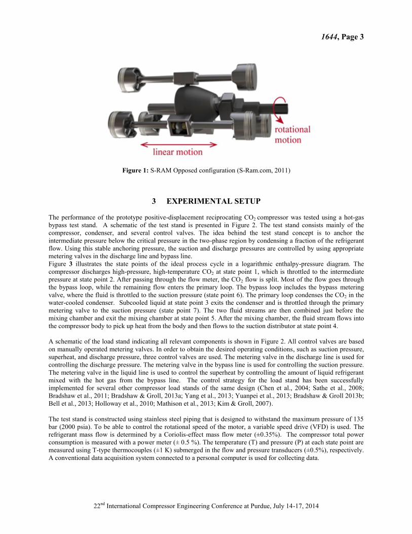
bypass test stand. A schematic of the test stand is presented in Figure 2. The test stand consists mainly of the
compressor, condenser, and several control valves. The idea behind the test stand concept is to anchor the
intermediate pressure below the critical pressure in the two-phase region by condensing a fraction of the refrigerant
flow. Using this stable anchoring pressure, the suction and discharge pressures are controlled by using appropriate
metering valves in the discharge line and bypass line.
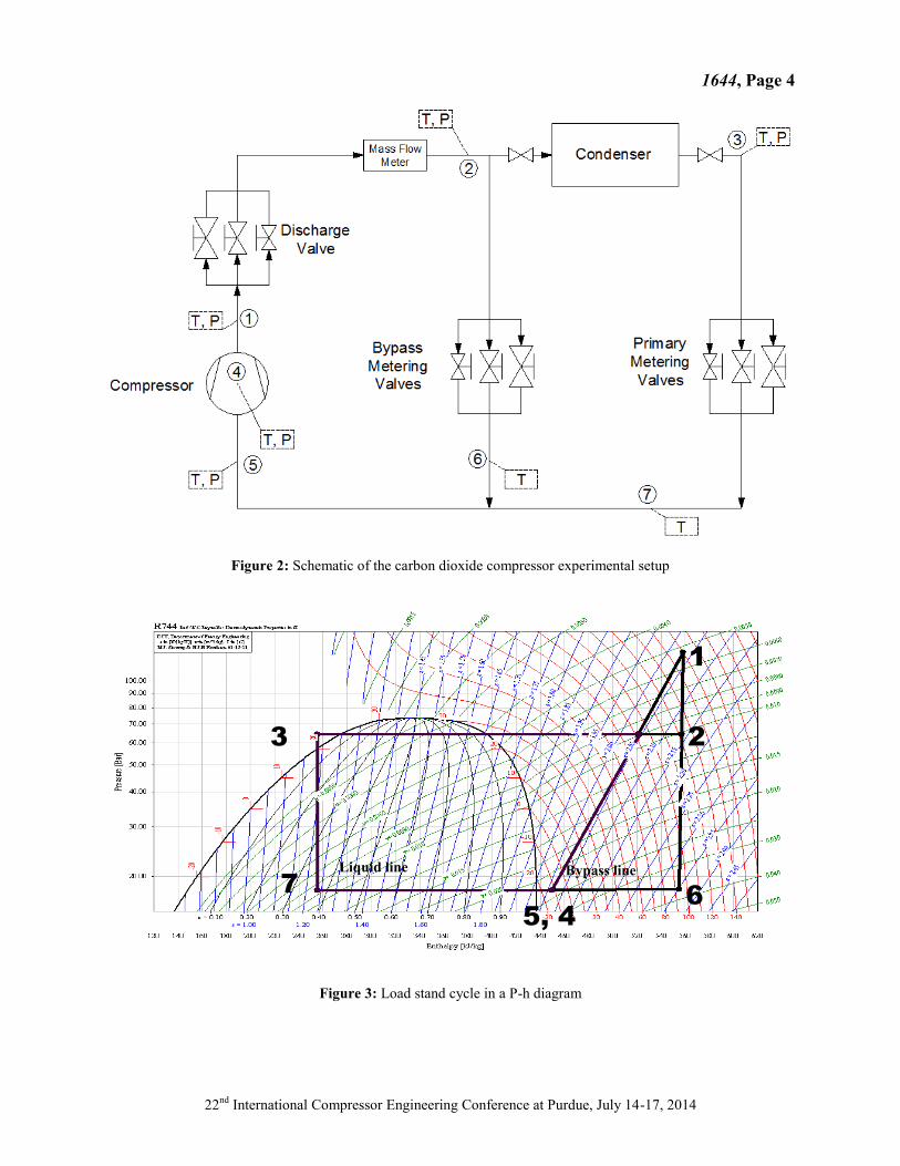
Figure 3 illustrates the state points of the ideal process cycle in a logarithmic enthalpy-pressure diagram. The
compressor discharges high-pressure, high-temperature CO2 at state point 1, which is throttled to the intermediate
pressure at state point 2. After passing through the flow meter, the CO2 flow is split. Most of the flow goes through
the bypass loop, while the remaining flow enters the primary loop. The bypass loop includes the bypass metering
valve, where the fluid is throttled to the suction pressure (state point 6). The primary loop condenses the CO2 in the
water-cooled condenser. Subcooled liquid at state point 3 exits the condenser and is throttled through the primary
metering valve to the suction pressure (state point 7). The two fluid streams are then combined just before the
mixing chamber and exit the mixing chamber at state point 5. After the mixing chamber, the fluid stream flows into
the compressor body to pick up heat from the body and then flows to the suction distributor at state point 4.
A schematic of the load stand indicating all relevant components is shown in Figure 2. All control valves are based
on manually operated metering valves. In order to obtain the desired operating conditions, such as suction pressure,
superheat, and discharge pressure, three control valves are used. The metering valve in the discharge line is used for
controlling the discharge pressure. The metering valve in the bypass line is used for controlling the suction pressure.
The metering valve in the liquid line is used to control the superheat by controlling the amount of liquid refrigerant
mixed with the hot gas from the bypass line. The control strategy for the load stand has been successfully
implemented for several other compressor load stands of the same design (Chen et al., 2004; Sathe et al., 2008;
Bradshaw et al., 2011; Bradshaw & Groll, 2013a; Yang et al., 2013; Yuanpei et al., 2013; Bradshaw & Groll 2013b;
Bell et al., 2013; Holloway et al., 2010; Mathison et al., 2013; Kim & Groll, 2007).
The test stand is constructed using stainless steel piping that is designed to withstand the maximum pressure of 135
bar (2000 psia). To be able to control the rotational speed of the motor, a variable speed drive (VFD) is used. The
refrigerant mass flow is determined by a Coriolis-effect mass flow meter (±0.35%). The compressor total power
consumption is measured with a power meter (± 0.5 %). The temperature (T) and pressure (P) at each state point are
measured using T-type thermocouples (±1 K) submerged in the flow and pressure transducers (±0.5%), respectively.
A conventional data acquisition system connected to a personal computer is used for collecting data.
1644, Page 4
22nd
International Compressor Engineering Conference at Purdue, July 14-17, 2014
Figure 2: Schematic of the carbon dioxide compressor experimental setup
Figure 3: Load stand cycle in a P-h diagram
5, 4
1
2 3
7 6
Bypass line Liquid line
1644, Page 5
22nd
International Compressor Engineering Conference at Purdue, July 14-17, 2014
4 RESULTS AND ANALYSIS
4.1 Compressor specifications and test method The prototype compressor is a single-stage, single-ended, oil-free open-drive reciprocating compressor with an
estimated cooling capacity of 80 kW at 90 bars and a PR of 3, while running at 1800 rpm. The compressor is the
first prototype of the single-ended piston mechanism design with 5 pistons, 345 cm3 displacement and 37.25 m
3/hr
@ 1800 rpm. The motor power is 60 HP, 460 V, 69 amps at 1800 rpm. At full load, it can generate a torque of
240.65 N-m.
The compressor body was modified to remove heat by connecting the suction line to the body and run refrigerant
through the body. The superheated refrigerant was then connected to the distributor of the compressor suction port.
The compressor body case is designed to hold 35 bars in the case. Because of safety concerns, a relief valve is
attached to the compressor case, which was set to release CO2 into the environment at pressures of higher than 35
bars.
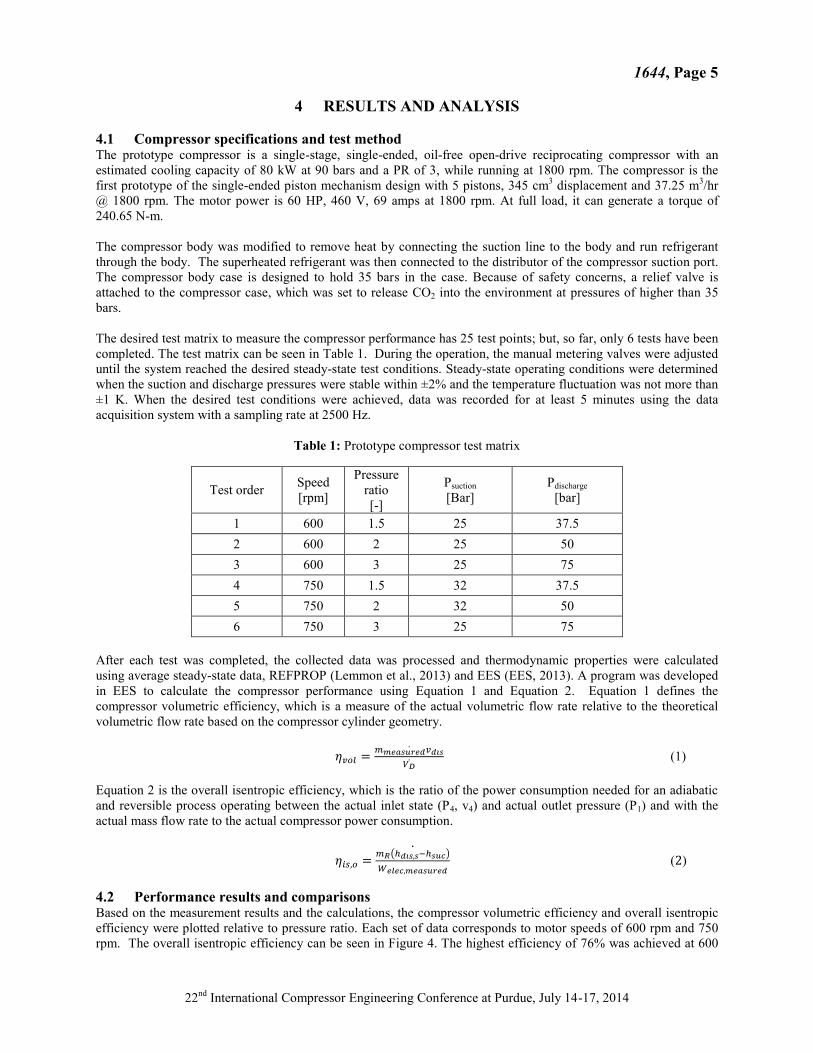
The desired test matrix to measure the compressor performance has 25 test points; but, so far, only 6 tests have been
completed. The test matrix can be seen in Table 1. During the operation, the manual metering valves were adjusted
until the system reached the desired steady-state test conditions. Steady-state operating conditions were determined
when the suction and discharge pressures were stable within ±2% and the temperature fluctuation was not more than
±1 K. When the desired test conditions were achieved, data was recorded for at least 5 minutes using the data
acquisition system with a sampling rate at 2500 Hz.
Table 1: Prototype compressor test matrix
Test order Speed
[rpm]
Pressure
ratio
[-]
Psuction
[Bar]
Pdischarge
[bar]
1 600 1.5 25 37.5
2 600 2 25 50
3 600 3 25 75
4 750 1.5 32 37.5
5 750 2 32 50
6 750 3 25 75
After each test was completed, the collected data was processed and thermodynamic properties were calculated
using average steady-state data, REFPROP (Lemmon et al., 2013) and EES (EES, 2013). A program was developed
in EES to calculate the compressor performance using Equation 1 and Equation 2. Equation 1 defines the
compressor volumetric efficiency, which is a measure of the actual volumetric flow rate relative to the theoretical
volumetric flow rate based on the compressor cylinder geometry.
(1)
Equation 2 is the overall isentropic efficiency, which is the ratio of the power consumption needed for an adiabatic
and reversible process operating between the actual inlet state (P4, v4) and actual outlet pressure (P1) and with the
actual mass flow rate to the actual compressor power consumption.
( )
( )
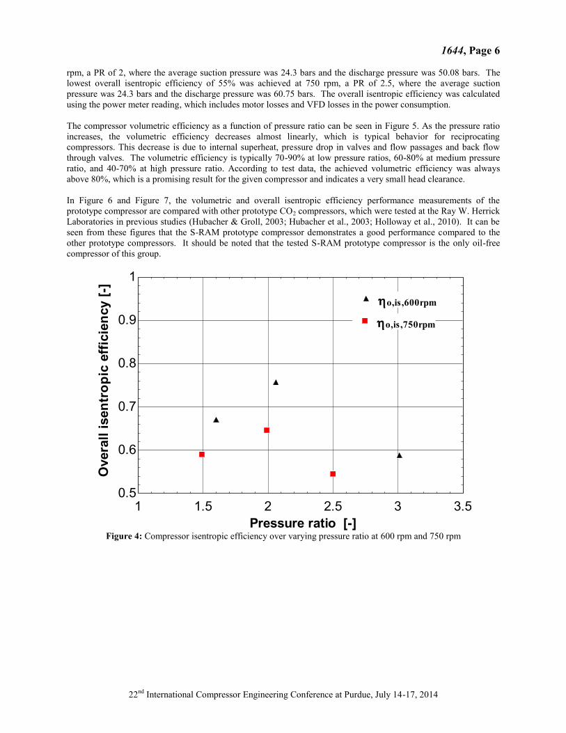
4.2 Performance results and comparisons Based on the measurement results and the calculations, the compressor volumetric efficiency and overall isentropic
efficiency were plotted relative to pressure ratio. Each set of data corresponds to motor speeds of 600 rpm and 750
rpm. The overall isentropic efficiency can be seen in Figure 4. The highest efficiency of 76% was achieved at 600
1644, Page 6
22nd
International Compressor Engineering Conference at Purdue, July 14-17, 2014
rpm, a PR of 2, where the average suction pressure was 24.3 bars and the discharge pressure was 50.08 bars. The
lowest overall isentropic efficiency of 55% was achieved at 750 rpm, a PR of 2.5, where the average suction
pressure was 24.3 bars and the discharge pressure was 60.75 bars. The overall isentropic efficiency was calculated
using the power meter reading, which includes motor losses and VFD losses in the power consumption.
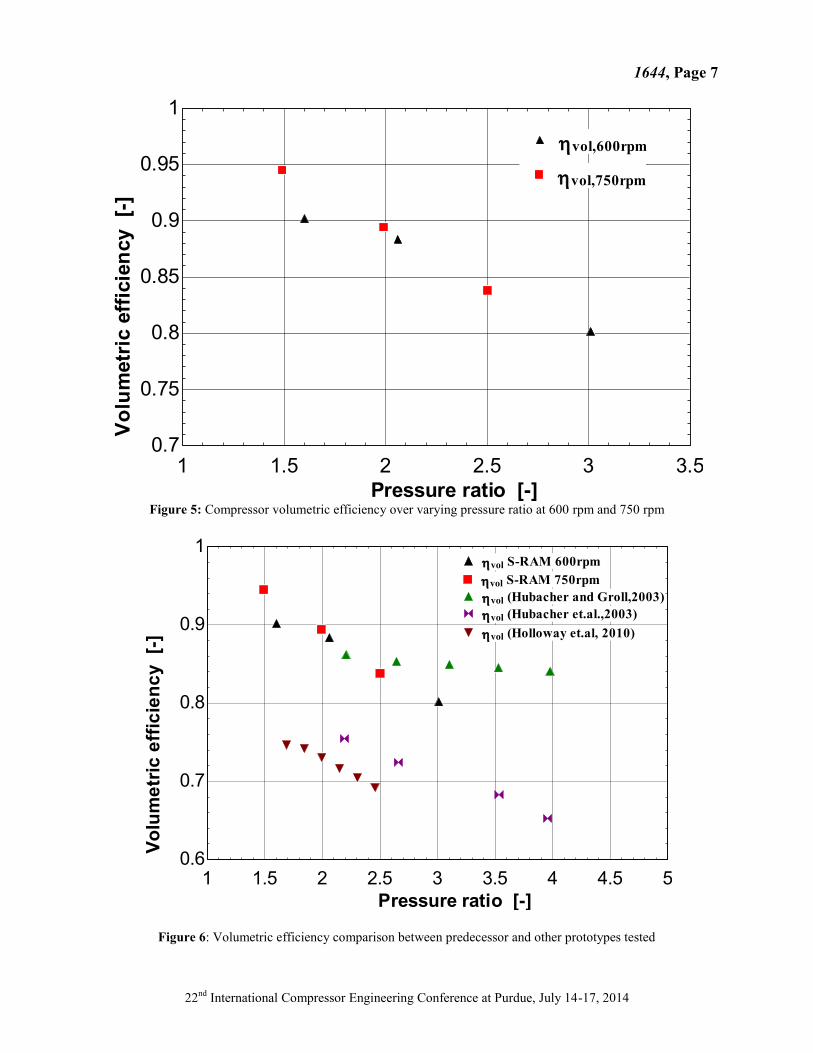
The compressor volumetric efficiency as a function of pressure ratio can be seen in Figure 5. As the pressure ratio
increases, the volumetric efficiency decreases almost linearly, which is typical behavior for reciprocating
compressors. This decrease is due to internal superheat, pressure drop in valves and flow passages and back flow
through valves. The volumetric efficiency is typically 70-90% at low pressure ratios, 60-80% at medium pressure
ratio, and 40-70% at high pressure ratio. According to test data, the achieved volumetric efficiency was always
above 80%, which is a promising result for the given compressor and indicates a very small head clearance.
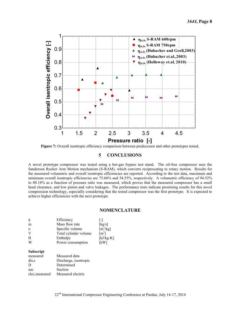
In Figure 6 and Figure 7, the volumetric and overall isentropic efficiency performance measurements of the
prototype compressor are compared with other prototype CO2 compressors, which were tested at the Ray W. Herrick
Laboratories in previous studies (Hubacher & Groll, 2003; Hubacher et al., 2003; Holloway et al., 2010). It can be
seen from these figures that the S-RAM prototype compressor demonstrates a good performance compared to the
other prototype compressors. It should be noted that the tested S-RAM prototype compressor is the only oil-free
compressor of this group.
Figure 4: Compressor isentropic efficiency over varying pressure ratio at 600 rpm and 750 rpm
1 1.5 2 2.5 3 3.50.5
0.6
0.7
0.8
0.9
1
Pressure ratio [-]
Overa
ll i
sen
tro
pic
eff
icie
ncy [
-]
ho,is,600rpmho,is,600rpm
ho,is,750rpmho,is,750rpm
1644, Page 7
22nd
International Compressor Engineering Conference at Purdue, July 14-17, 2014
Figure 5: Compressor volumetric efficiency over varying pressure ratio at 600 rpm and 750 rpm
Figure 6: Volumetric efficiency comparison between predecessor and other prototypes tested
1 1.5 2 2.5 3 3.50.7
0.75
0.8
0.85
0.9
0.95
1
Pressure ratio [-]
Vo
lum
etr
ic e
ffic
ien
cy
[-]
hvol,600rpmhvol,600rpm
hvol,750rpmhvol,750rpm
1 1.5 2 2.5 3 3.5 4 4.5 50.6
0.7
0.8
0.9
1
Pressure ratio [-]
Vo
lum
etr
ic e
ffic
ien
cy
[-
]
hvol S-RAM 600rpmhvol S-RAM 600rpm
hvol S-RAM 750rpmhvol S-RAM 750rpm
hvol (Hubacher and Groll,2003)hvol (Hubacher and Groll,2003)
hvol (Hubacher et.al.,2003)hvol (Hubacher et.al.,2003)
hvol (Holloway et.al, 2010)hvol (Holloway et.al, 2010)
1644, Page 8
22nd
International Compressor Engineering Conference at Purdue, July 14-17, 2014
Figure 7: Overall isentropic efficiency comparison between predecessor and other prototypes tested.
5 CONCLUSIONS
A novel prototype compressor was tested using a hot-gas bypass test stand. The oil-free compressor uses the
Sanderson Rocker Arm Motion mechanism (S-RAM), which converts reciprocating to rotary motion. Results for
the measured volumetric and overall isentropic efficiencies are reported. According to the test data, maximum and
minimum overall isentropic efficiencies are 75.66% and 54.55%, respectively. A volumetric efficiency of 94.52%
to 80.18% as a function of pressure ratio was measured, which proves that the measured compressor has a small
head clearance, and low piston and valve leakages. The performance tests indicate promising results for this novel
compression technology, especially considering that the tested compressor was the first prototype. It is expected to
achieve higher efficiencies with the next prototype.
NOMENCLATURE
Efficiency [-]
m Mass flow rate [kg/s]
𝜐 Specific volume [m3/kg]
V Total cylinder volume [m3]
H Enthalpy [kJ/kg-K]
W Power consumption [kW]
Subscript
measured Measured data
dis,s Discharge, isentropic
D Determined
suc Suction
elec,measured Measured electric
1 1.5 2 2.5 3 3.5 4 4.50.3
0.4
0.5
0.6
0.7
0.8
0.9
1
Pressure ratio [-]
Overa
ll i
sen
tro
pic
eff
icie
ncy [
-]
ho,is S-RAM 600rpmho,is S-RAM 600rpm
ho,is S-RAM 750rpmho,is S-RAM 750rpm
ho,is (Hubacher and Groll,2003)ho,is (Hubacher and Groll,2003)
ho,is (Hubacher et.al.,2003)ho,is (Hubacher et.al.,2003)
ho,is (Holloway et.al, 2010)ho,is (Holloway et.al, 2010)

1644, Page 9
22nd
International Compressor Engineering Conference at Purdue, July 14-17, 2014
REFERENCES Adolph, U. (1995). Einsatz von CO2 als Kaeltemittel in Schienenfahrzeugen. FKW Seminar XVII. FKW GmbH,
Hannover, Germany.
Chen, Y., Groll, E. A., & Braun, J. E. (2004) Modeling of hermetic scroll compressor: Model validation and
application. HVAC&R Research, 10(3), 307-32.
Bell, I. H., Groll, E. A., Braun, J. E., & Horton, W. T. (2013) Experimental testing of an oil-flooded hermetic scroll
compressor. International Journal of Refrigeration, 36 (7), 1866-1873.
Bradshaw, C.R., Groll, E.A.,& Garimella, S.V. (2011) A comprehensive model of a miniature-scale linear
compressor for electronics cooling. International Journal of Refrigeration, 34(1), 63-73.
Bradshaw, C. R., & Groll, E. A. (2013) A comprehensive model of a novel rotating spool compressor. International
Journal of refrigeration, 36(7), 1974-1981.
EES version 9.434-3D, 2013, Madison, WI: F-Chart Software.
Fagerli, B.E. (1996a). An Investigation of Possibilities for CO2 Compression in a Hermetic Compressor. Proc. IIR
Conf., Applications for Natural Refrigerants. Aarhus, Denmark, Sept. 3-6, 639-649.
Fagerli, B.E. (1996b).Development and Experiences with a Hermetic CO2 Compressor. International Compressor
Engineering Conference. Purdue University West Lafayette, IN, July 23-26, 229-235.
Fagerli, B.E. (1997). CO2 Compressor Development. Proc. IEA Heat Pump Centre/IIR Workshop on CO2
Technology in Refrigeration, Heat Pump & Air Conditioning Systems. Trondheim, Norway, May 13-14.
Hasegawa, H., Ikoma, M., Nishiwaki, F., Shintaku, H. & Y. Yakumaru. (2000) Experimental and Theoretical Study
of Hermetic CO2 Scroll Compressor. 4th IIR–Gustav Lorentzen Conference on Natural Working Fluids, Purdue
University.West Lafayette, IN, July 25-28, 347-353.
Holloway, S., Horton T.W., Groll, E.A., Sherman, D., & Albertin M. (2010) Experimental Performance of a
Prototype Carbon Dioxide Compressor. International Compressor Engineering Conference. Purdue University,
West Lafayette, IN 2010-01-01T08:00:00Z.
Hubacher, B., & Groll, E.A. (2003)Performance Measurements of a Hermetic, Two-Stage Carbon Dioxide
Compressor. International Congress of Refrigeration. Washington, DC, Paper 0029.
Hubacher, B.; Groll, E. A.; & Hoffinger, C. (2002) Performance Measurements of a Semi-Hermetic Carbon Dioxide
Compressor. International Refrigeration and Air Conditioning Conference. Purdue University, West Lafayette,
IN.
Hwang, Y., & R. Radermacher. (1998) Development of Hermetic Carbon Dioxide Compressor. Proc. International
Refrigeration Conf. at Purdue. West Lafayette, IN, July 14-17, 171-176.
Inagaki, M., Sasaya, H. & Y. Ozakli. (1997).Pointing into the Future: Two-Stage CO2 Compression. Proc. IIR
Conf., Heat Transfer Issues in Natural Refrigerants. College Park, MD, Nov. 6-7, 131-138.
Jorgensen, S. T. (1998) Variable Automotive CO2 Compressor. International Refrigeration Conference Purdue
University. West Lafayette, IN, July 14-17, 159-164.
Kim, J.H.,& Groll, E.A., 2007, “Feasibility study of a bowtie compressor with novel capacity modulation”,
International Journal of Refrigeration, 30(8), pp.1427-1438.
Kruse, H., & J. Suess, 1996, “Research on the Behavior of Refrigeration Compressors Using CO2 as the
Refrigerant, International Compressor Engineering Conference, Purdue University, West Lafayette, IN, July
23-26, pp. 223-228.
Koehler, J., Kaiser, H., & B. Lauterbach. (1997) CO2 as Refrigerant for Bus Air Conditioning and Transport
Refrigeration. Trondheim, Norway, May 13-14.
Lemmon, E.W., Huber, M.L., & McLinden, M.O. (2013) NIST Standard Reference Database 23: Reference Fluid
Thermodynamic and Transport Properties-REFPROP, Version 9.1, National Institute of Standards and
Technology, Standard Reference Data Program, Gaithersburg.
Mathison, M.M., Braun, J.E., & Groll, E.A. (2013) Modeling of a novel spool compressor with multiple vapor
refrigerant injection ports. International Journal of Refrigeration, 36(7), 1982-1997.
Sathe, A. A., Groll, E. A., & Garimella, S. V. (2008) Experimental Evaluation of a Miniature Rotary Compressor for
Application in Electronics Cooling. CTRC Research Publications 2008-01-01T08:00:00Z
Song, Y., Groll, E.A., & Braun, J.E. (2013) Modeling and experimental validation of a multi-port vapor injected
scroll compressor. Master thesis 2013-01-01T08:00:00Z.
Suess, J. (1999) Untersuchung zur Konstruktion moderner Verdichter für Kohlendioxid als Kältemittel. Deutscher
Kälte und Klimatechnischer Verein (1999), ISBN-10: 3932715624.

1644, Page 10
22nd
International Compressor Engineering Conference at Purdue, July 14-17, 2014
Yang, B,Bradshaw, C.R., & Groll, E.A. (2013) Modeling of a semi-hermetic CO2 reciprocating compressor
including lubrication submodels for piston rings and bearings. International Journal of Refrigeration, 36(7),
1925-1937