Embed Size (px)
Citation preview

Trelleborg Offshore Products and solutions 2018
Performanceat every level

Seismic 3
Seismic Bend Stiffener 4
Seismic Cable Handling 5
Seismic Towing Attachments 6
Seismic Towing Ancillaries 7
Drilling & Downhole 9
Crushable Foam Wrap 10
Drill Riser Buoyancy 11
RiserGuard 12
Helically Grooved Buoyancy 13
Engineering 14
Engineering design, analysis and simulation 15
Subsea 17
Bend Restrictor 18
Bend Stiffener 19
Distributed Buoyancy Modules 20
J-Tube Seals 21
Piggy Back Guide 22
Piggy Back Clamp 23
Eccofloat® 24
Subsea Centralizers 25
Tri-Strakes™ Lite 26
Tri-Strakes™ Stinger 27
Tri-Strakes™ Combi 28
Uraduct® 29
Buoyant Uraduct® 30
Vikotherm® 31
Vikotherm® E1 & E2 32
Vikotherm® PT 32
Vikotherm® G3 33
Vikotherm® P7 33
Vikotherm® PP 34
Vikotherm® S1 34
Vikotherm® R2 35
Nano Buoy 36
Subsea Spherical & Ellipsoidal Buoys 37
Standardized Buoyancy Modules 38
Rotating Buoyancy Modules 39
Polymat™ 40
Polyspace 41
Trimsyn™ & Trimlok™ 42
Deepwater performance in Brazil 43
Topside 45
DryFoam™ 46
Elastopipe™ 47
FireNut™ 48
FireStop™ 49
FireStop™ Rigid Riser 50
Mobile Production Unit (MPU) 51
Vikodeck™ 52
Norflex™ Expansion Joints 53
Drain Gully 54
Escape Tunnel Seal 55
Linear Seal 56
Radial Seal 57
Renewables 59
NjordGuard™ 60
Bend Restrictor 61
Bend Stiffener 62
J-Tube Seals 63
Subsea Centralizers 64
VIV Suppression Strakes 65
Uraduct® 66
Protected performance for floating windfarm 67
Manufacturing Facilities 69
Boston US, Houston US,
Krokstadelva NO, Macaé BR,
Retford UK, Rochdale UK,
Skelmersdale UK 70
Index

1
Core Capabilities Trelleborg is a world leader in engineered polymer solutions that seal, damp and protect critical applications in demanding environments. Its innovative engineered solutions accelerate performance for customers in a sustainable way. Using advanced polymer material technology, Trelleborg Offshore provides high integrity solutions for the harshest offshore environments. Trelleborg Offshore specializes in the development and production of polymers and syntactic foam, for all levels of the offshore industry. Our goal is to perform at every level to deliver innovative and reliable offshore solutions that maximize business performance to meet your needs.
Innovation With a long-standing commitment to the development of innovative polymer and syntactic foam-based solutions, Trelleborg Offshore provides superior engineered solutions serving the harshest and most demanding offshore applications. Trelleborg Offshore specializes in the development and production of polymer and syntactic foam based seismic, marine, buoyancy, cable protection, thermal insulation and rubber-based fire protection solutions for the offshore
industry. Highlighting our commitment to R&D activity, Trelleborg Offshore carries out research development programs in partnership with industry bodies such as SINTEF and collaborates with several schools, colleges and universities providing research and degree project assistance. Thanks to our industry leading R&D activity, Trelleborg Offshore is widely considered the supplier of choice for many key industry OEMs, contractors and operators.
Expertise Always keen to share our vast knowledge and application expertise with customers to help them accelerate their performance, now and in the future, we offer comprehensive engineering support from conception to completion of every project. This includes the training of customers on the capabilities of Trelleborg’s portfolio of polymer solutions and engineering support throughout a customers’ bid for a project (however large or small). In addition to providing expertise in polymer solutions for every kind of offshore application, we control the whole supply chain including design, manufacture, testing and installation to ensure the delivery of what you need, when you need it.
in engn ineeredgg polymerll solutionsnnTreii lleborggiigggg gnenerr isi as wdda orww lllrrd-ll leaderl

2

3
SeismicTrelleborg Offshore excels in the design and development of superior polymer engineered solutions for the harsh and demanding environments of international seismic and oil and gas markets.
Seismic Bend Control Solutions - Where any flexible tubular connects to a structure, normal movement during operation or forces incurred during installation can cause catastrophic failure of the tubular at the termination point. Our seismic bend control solutions reduce this damage.
Seismic Cable Handling - Seismic towed arrays are carefully designed to maximize survey efficiency. To enable the towed array to be set up correctly, it is necessary to attach various buoys, cross chains etc. To ensure the integrity of the towed array, these connection points must provide a secure and safe method of attachment.
Towing Attachments and Ancillaries - Seismic towed arrays undergo significant loading during operation. The towing forces from the vessel combine with drag from the sea and lateral loads from diverter and cross chains. These complex loads need to be correctly controlled to ensure that the seismic array operates correctly.
4
Where any cable or hose connects to a structure, normal movement during operation (dynamic loading) or forces incurred during installation and retrieval (static loading) can cause catastrophic failure of the cable or hose, at the termination point. The failure mode can be through collapse, rupture of internal lines or even rupture of the external layers leading to escape of the contents to the environment. This can happen as the result of a single event or be caused through fatigue damage over time.
Bend limiting devices are provided to protect the cable or hose from these situations and perform the following functions:• Maintain the manufacturers recommended minimum bend radius (MBR) during the life of the project• Provide a suitable load path from cable or hose, to fixed structure• Reduce point loading at the termination to an acceptable level
Bend Stiffener The Bend Stiffener acquired its name because the conical shape gradually increases the overall stiffness of the cable or hose in order to prevent over bending at the termination point. Manufactured from elastomeric material, a bend stiffener is suited to the constant wave and current induced motion of dynamic installations but can also be used for static applications.
Bend Stiffeners are project specific and fully engineered to accommodate the defined tension and angle combinations as Trelleborg Offshore strive to perform at every level to meet the customers’ needs. The two types of Bend Stiffeners are split and non-split bend stiffeners. These are offered in a variety of attachment methods, such as brackets, flanges & slide-on.
Protecting seismicsurvey cables
Bend Stiffener
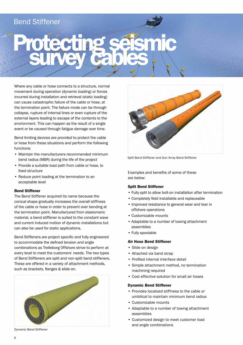
Examples and benefits of some of these are below:
Split Bend Stiffener
• Fully split to allow bolt-on installation after termination• Completely field installable and replaceable• Improved resistance to general wear and tear in offshore operations• Customizable mounts• Adaptable to a number of towing attachment assemblies• Fully spoolable
Air Hose Bend Stiffener
• Slide on design• Attached via band strap• Profiled internal interface detail• Simple attachment method, no termination machining required• Cost effective solution for small air hoses
Dynamic Bend Stiffener
• Provides localized stiffness to the cable or umbilical to maintain minimum bend radius• Customizable mounts• Adaptable to a number of towing attachment assemblies• Customized design to meet customer load and angle combinations
Split Bend Stiffener and Gun Array Bend Stiffener
Dynamic Bend Stiffener

5
Seismic towed arrays are carefully designed to maximize survey efficiency. To enable the towed array to be set up correctly, it is necessary to attach various buoys, cross chains etc. To ensure the integrity of the towed array, these connection points must provide a secure and safe method of attachment.
Trelleborg Offshore designs and manufactures specialist cable handling solutions to meet the exacting demands of marine seismic customers. Using our expertise in understanding the difficulties associated with working in such demanding conditions, our seismic cable handling solutions ensure the safe management and deployment of cables.
The cable handling solution range includes Super Boots, Cumberland Grips and Cumberland Sliders to meet your needs.
Safe deploymentof cables
Cable Handling
Cumberland Grip The Cumberland Grip is generally used on seismic survey towed cables or as an ocean bottom cable system for anchor weight attachment.
Benefits of a Cumberland Grip include:• Safe attachment of moderate load diverters and tow points to armored or sheathed cables• Integrated friction grip clamp and bend stiffeners to control cable curvature• Provides uniform grip over entire length• Fully split to allow easy attachment• Fully spoolable with yoke removed
Cumberland Slider The Cumberland Slider stabilizes large multi cable towed array systems during turning and alignment maneuvers.
Benefits of Cumberland Sliders include:• Easy movement over cable with clearance bore• Provides cable protection under sliding conditions• Sacrificial tip wear pad inserts• Fully spoolable with yoke removed
Super Boot The Super Boot is generally used on a seismic lead-in cable that must be linked at intervals to a parallel tow wire. It can also be used for protection of cables when floats are attached at certain points along a heavy tow cable.
Benefits of Super Boots include:• Safe coupling for sheathed or armored cables at mid-length• Integrated friction grip clamp and bend stiffeners to control cable curvature• Protection against over bending and chafing• Fully spoolable with bridle and yoke removed

6
Seismic towed arrays undergo significant loading during operation. The towing forces from the vessel combine with drag from the sea and lateral loads from diverter and cross chains. These complex loads need to be correctly controlled to ensure that the seismic array operates correctly.
Trelleborg Offshore designs and manufactures specialist towing attachments. Using our expertise in understanding the difficulties associated with working in demanding conditions, our towing attachments help protect the seismic survey cables from over bending and to increase the local stiffness of cables at the attachment point.
Our product line of towing attachments includes Lead-in Bend Assemblies, Umbilical Tow Point Protectors and Connector Mounted Assemblies.
Protecting seismic survey cables
Towing Attachments
Lead-in Bend Assembly The Lead-in Bend Assembly or Umbilical Tow Point Protector is used as an attachment point on seismic survey cables for towing applications. The assembly protects the cable from over bending by increasing the local stiffness of the cable at the attachment point. A Lead-in Bend Assembly allows for assembly over a pre-terminated cable and is generally used on seismic survey lead-in cables to attachment towing chains, paravane type diverters or flotation.
Advantages of a Lead-in Bend Assembly include:• Oversized bore bend stiffener with color coded packers to suite numerous cable sizes• Allows for assembly over pre-terminated cable• High grip capacity on the lead-in cable• Ideal attachments for diverter and tether head
Umbilical Tow Point Protector The Umbilical Tow Point Protector is specifically designed to aid attachment of a tow point to the gun umbilical. Advantages of the Umbilical Tow Point Protector include:• Helical rods to ensure integrity of the gun umbilical• Helical rods and olive arrangement ensure that the tow point has significant grip capacity
Helical Rod System
Connector Mounted Assembly The Connector Mounted Assembly is designed for mounting onto the Lead-in or Streamer Connector and meets the different protection requirements. Advantages of the Connector Mounted Assembly include:• Principle application as per lead-in assembly• Internal clamp profile to suite termination• Full cable strength attachment point

7
Helical Rod System The Helical Rod System is a robust set of helically twisted wires, supplied with end caps so that no sharp edges are present on the outer surface of the cable. Advantages of Helical Rod Systems include:• Localized abrasion resistance to cable• Increased grip capacity by spreading the load over a greater area of cable• Superior grip capacity at connection point when used in conjunction with Tow Point Protectors
Information needed to specify Helical Rod System:• Cable diameter and tolerances• Required length of rods (typically 2 m or 3.6 m sets), larger lengths are available• Galvanized or Stainless Steel
Improving safety for cable handling is one of the ways Trelleborg Offshore performs at every level to ensure we protect people, the environment and infrastructure investments. Our towing ancillary equipment is designed to increase efficiently and improve safety during usage.
Protecting seismic survey cables
Towing Ancillaries
Multiple Ballast Weight Assembly The Multiple Ballast Weight Assembly provides a secure and easy to handle ballast for attachment to lead-in cables. Typical ballast weights are 75 kg, 100 kg and 150 kg, although ballast weights can be tailored to your needs.
Advantages of Multiple Ballast Weight Assemblies include:• Secure attachment to lead-in cable• Integral bend stiffeners ensure load is spread over the length of the unit• Lead-free ballast solution
Information needed to specify Multiple Ballast Weight Assembly:• Cable diameter and tolerances• Cable outer jacket material

8

9
Drilling & DownholeServing the drilling and downhole market for well over forty years, Trelleborg Offshore has an extensive range of reliable, cutting edge polymer engineered products and solutions.
Drill Riser Buoyancy - The drill riser provides a conduit for the drill string and drilling fluids from the ocean floor to the rig. This has significant weight which must be supported by its own structure and ultimately by the drilling vessel. In order to reduce this weight in water to a more manageable amount, discrete buoyancy units are fitted along the length of the riser.
Riser Attachments & Ancillaries - Designed to complement the rigid Drill Riser Buoyancy Modules (DRBMs) so that there is a comprehensive level of support while ensuring a seamless installation of the riser system.
Riser Protection - Protects people, structures and equipment from all types of fire and corrosion in the offshore environment, as well protecting the riser itself. In the demanding environment offshore it is paramount to ensuring on-board safety.
Crushable Foam Wrap - Designed to be installed around the inner drill casing which is then immersed within the annulus fluid. As the pressure of the annulus fluid increases, the Crushable Foam Wrap will collapse at a pre-determined pressure/temperature combination, allowing expansion of the annulus fluid and dispersing any potentially destructive pressure increases.

10
When subsea wells are completed, liquid becomes trapped at fairly low temperatures between the outer wall of one casing string and the inner wall of another – in the casing annulus. Heat generated during production operations can cause the trapped fluids to expand and potentially create pressures in excess of 10,000 psi.
If not managed, annular pressure build-up (APB) induced loads can compromise well integrity during production, either by collapsing the inner casing or bursting the outer one.
The most effective mitigation solution for APB is to allow the fluid trapped within the casing annulus to expand, when critical pressure levels are reached. Crushable Foam Wrap from Trelleborg Offshore is installed in the trapped annulus during well construction and it is designed to collapse before any potentially dangerous pressure occurs, allowing the trapped fluid to expand. Trelleborg offer a wide range of syntactic foam grades, available to fit a variety of annular geometries, to cater for the protection of all wells, in virtually any combination of temperature and pressure. Crushable Foam Wrap is a proven engineered solution for APB mitigation with more than 20 years of successful application for the major operators in the O&G industry.
Crushable Foam Wrap from Trelleborg Offshore is a rigid polymeric material which has a closed cell foam micro structure allowing for collapse of the foam within a specified temperature and pressure band as dictated by the expected well conditions.
Preventingexcessive pressure
Crushable Foam Wrap
Operator
BP
BP
Shell
Total
Tullow oil
Repsol
Weatherford
Name of the Field
Machar I, II, III
Mad Dog
Ram Powell
Akpo
TEN
BM – C33
Eni
Location
North Sea
Gulf of Mexico
Gulf of Mexico
West Africa
Ghana
Brazil
North Sea
CFW INSTALLED PROJECTS
Crushable Foam Wrap panels shown during installation.
In the start-up phase, the materials remain intact, with no significant volume change. If conditions reach certain preset limits the syntactic foam undergoes a progressive and significant collapse, preventing excessive overpressure and thus protecting the steel casing.
Benefits:
• Easy to handle and install, chemically inert material• Onsite installation available • Honeycomb microstructure allows collapse of the foam to take place and remain intact• May be placed anywhere within the trapped annulus• Allows easy circulation of drilling fluids• Collapse after the maximum operating temperature is reached• Reduced risk of cracking• Proven track record

11
Benefits:
• Enhanced safety – Ultra M.I.S.• Increased mechanical strength• Optimized uplift
In offshore drilling operations, the drill riser provides a conduit for the drill string from the ocean floor to the rig. However, this adds significant weight which must be supported by its own structure and ultimately by the drilling vessel. Reducing overall weight in water to a manageable amount is critical in expanding exploration and resource recovery to ultra deepwater fields.
Trelleborg Offshore offers Drill Riser Buoyancy Modules (DRBM) to safely overcome these operational challenges. The DRBMs are fitted along the length of the riser to reduce the weight of the drilling riser to a manageable level. We work with our customer at all stages of the project life cycle to ensure all project requirements are met or exceeded.
Drill Riser Buoyancy operates in the harshest of marine environments. These challenging conditions can have a detrimental effect on Drill Riser Buoyancy resulting in cracked or broken buoyancy elements. To safely mitigate these hazardous conditions, Trelleborg Offshore developed the Ultra M.I.S. (Module Integrity System) range of Drill Riser Buoyancy. The Ultra M.I.S. system is a safety system which ensures a damaged buoyancy element can be safely recovered and repaired and also provides a significant increase in mechanical strength to ensure robust and reliable performance.
Drilling and syntacticproducts
Drill Riser Buoyancy
To provide you with performance at every level, we offer a wide range of riser ancillaries designed to complement our Drill Riser Buoyancy Systems. These include RiserGuard, Riser Shims, Stop Collars, Installation Hardware, Riser Grommets & Polykap protectors.

12
Benefits:
• Complete protection of bare riser joint and external lines • Same OD & geometry as buoyancy • Light weight material (neutrally buoyant/free flooding in seawater)• Excellent abrasion and impact resistance• Stackable
In offshore drilling operations, the drill riser provides a conduit for the drill string from the ocean floor to the rig. However, the bare drilling riser (riser which does not have DRBM – Drilling Riser Buoyancy Modules installed) also requires protection. Replacing traditional metallic solutions for protection of risers with a composite based modular design increases performance by weight reduction and improves safety during handling, storage and drilling operations.
RiserGuard provides complete protection of bare riser joints and external lines during handling, storage, and drilling operations. They are specifically designed to protect the drilling riser from impact damage when running or retrieving through the moon pool area, or during handling operations in the riser storage bay.
Stackable RiserGuard Stackable RiserGuard is a solution for rigs with limited storage space and allows stacking of various types of riser joints. It provides the same protection and handling characteristics as standard RiserGuard while adding strategically spaced molded polyurethane sections between the RiserGuard which transfers the load between bare joints and deck storage area. This provides the capability to efficiently store various types of riser joints while preserving valuable deck space.
Riser Shims Riser Shims support bare joints in critical areas of the riser joint. They are installed at intervals on the riser joint and constructed to the same external configuration as the buoyancy, facilitating the stacking of bare joints. Riser Shims do not provide full joint protection but offer an economic protective solution.
To provide you with performance at every level, we offer a wide range of riser ancillaries designed to complement our Drill Riser Buoyancy systems & Bare Joint Protection systems. These include Stop Collars, Installation Hardware, Riser Grommets & Polykap protectors.
Bare riserprotection systems
RiserGuard

13
Drill riser buoyancy VIV suppression
Helically Grooved Buoyancy
Helically grooved buoyancy is the result of a joint development between Trelleborg Offshore and Diamond Offshore Drilling to integrate vortex-induced vibration (VIV) suppression and drag reduction with drill riser buoyancy, increasing rig efficiency without compromising on safety or structural integrity.
Helically grooved buoyancy design dimensions are optimized to ensure uncompromised uplift while effectively eliminating riser motions and higher levels of drag in onerous offshore current environments compared to traditional riser buoyancy. The minimal removal of material associated with the grooves corresponds to only a 2-3% buoyancy loss, which can easily be recovered through the manufacturing process by selecting lower density materials.
The new multi-functional design integrates VIV suppression and drag reduction technology into DRBM equipment from the time of manufacturing eliminating the requirement of ancillary suppression equipment, alleviating complicated and time intensive riser running and retrieval procedures. In addition, reductions in riser motions due to VIV limit the number and magnitude of strain cycles transferred to subsea equipment, in turn, decreasing fatigue loading and extending the service life of wellhead and conductor/casing equipment.
Joint handling times and running methodologies during riser deployment and retrieval are equivalent between Helical Grooved Buoyancy and traditional buoyancy designs, resulting in increased personnel safety, higher efficiency and a more robust solution compared to traditional VIV mitigation equipment.
Applications: • Marine Drilling Risers • Intervention Risers• Jumpers • Long Pipeline Spans• Production Risers • Umbilicals• Flow Lines • Power Cables
Benefits: • Expanded connected riser drilling & non-drilling operating envelopes• Increased vessel transiting speeds with a drilling riser deployed• Decreased riser and BOP excursion after disconnect• Increased maximum allowable current conditions for riser deployment, retrieval, and hang-off operations• Increased fatigue lives for the drilling riser and subsea equipment• Increased Personnel safety during riser deployment and retrieval over other ancillary VIV mitigation equipment• Simplified riser running procedures• Decreased demand on vessel station keeping propulsion systems

14
Analysis and simulation
Engineering
Refinement of concept, feasibility, and design through numerical modelling using computational fluid dynamics (CFD) and finite element analysis (FEA) allows Trelleborg Offshore to incorporate requirements for product performance, development, and operation life cycle maintenance throughout all stages of development. Incorporating this ability with increased communication and collaboration with drilling contractors and E&P operators in the front end design phase is resulting in the increase of equipment and technology that provides focused solutions to specific industry challenges.
Computational Fluid Dynamics Through the use of CFD, Trelleborg Offshore is collaborating with industry partners in developing new solutions for combating offshore equipment loading due to high current conditions. Product design and equipment configuration can be efficiently assessed prior to manufacturing operations to ensure the optimization of product vortex-induced vibration (VIV) suppression and drag reduction, translating to less stress on the equipment.
Local & Global Finite Element Analysis Detailed FEA allows Trelleborg Offshore to optimize equipment design through geometrical configurations, material make up, fastening solutions, and overall discrete and system performance. This vastly increases the successof new technology developments while simultaneously reducing the development life cycle and upfront investments, which enables Trelleborg Offshore to provide effective solutions to the client at much lower costs.
Product Performance Assessments Trelleborg Offshore extends the experience and capabilities of the in-house engineering analysis and simulation team beyond the office setting to a diversified variety of product qualifying trials.
During this stage of the design all of the collaborative input and innovation of Trelleborg Offshore and our industry partners and clients is verified and validated. Data obtained during laboratory testing provides the necessary information quantifying the performance of new technology developments and validating numerical models for future equipment advancements.
Applications:
• New Product Development• Equipment Performance Studies• System Integration Optimizations
Benefits:
• Cost savings• Increased service life• Multi-functional designs• Rapid development cycle

15
simulationProject Trelleborg Offshore was asked to manufacture and supply a protection system for an umbilical crossing associated with Vashishta and S1 Development Project for an EPCI customer. The protection system is intended for subsea umbilical applications, at a location where the umbilical crosses over the two existing 14” pipelines 35m apart. The targeted design life is 20 years in approximately 700m water depth.
Product and Service Uraduct™ was identified as the most appropriate solution for the umbilical protection. Trelleborg’s Uraduct™ product design team proposed two designs that met the requirement for minimum separation of 150 mm and 300 mm between the umbilical and existing pipelines. To ensure the technical requirements for the umbilical crossing protection system were met, Trelleborg’s engineering analysis and simulation team performed a series of global finite element analyses to validate the design which included:
• Umbilical stability analysis at the crossing location to ensure the stability of the umbilical along with the protection system meets DNV-RP-F109 requirements during the installation and operation phases, particularly when subject to hydrodynamic loading
• Umbilical crossing analysis to determine the naturally laid free span length at either side of the crossing over existing pipelines. The final radius of the umbilical crossing configuration with the installed protection system after laying on top of the 14” gas pipeline meet the umbilical’s minimum bend radius requirement
• Umbilical free span VIV (Vortex Induced Vibration due to sea bottom current) analysis to identify if the natural free span length has potential VIV occurrence concern
Engineering design, analysis and simulation
Drilling and Downhole Application:
Challenges and Solution The biggest challenge of the project was the very tight product delivery timeframe, which required rapid execution of product design and engineering analysis to ensure sufficient time for manufacturing. The engineering analysis and simulation team quickly arranged resources, prioritized the project and provided quick response to all the client’s inquiries. The engineering analysis team also performed design optimization analyses and coordinated with product design team to ensure best solutions were offered to the customer.
Through the analysis, potential VIV occurrence was identified due to the onerous sea bottom current in 100 year return period. Trelleborg presented the study findings to the client and proposed VIV suppression strakes as a replacement of Uraduct™ to avoid vibration damage to the umbilicals.
The rapid turn-around of the comprehensive analysis and the recommended Trelleborg VIV suppression solutions allow the client to progress with the original umbilical installation plan and avoided the necessity of revising the field installation design.
Calculated Free-Span Configuration for 300mm separation design FEA model

16

17
SubseaFrom subsea mooring to buoyancy, Trelleborg Offshore boasts an extensive range of innovative solutions, serving the subsea sector.
Bend Control Solutions - Where any flexible tubular connects to a structure, normal movement during operation or forces incurred during installation can cause catastrophic failure of the tubular at the termination point. Our bend control solutions reduce this damage.
Buoyancy - In floating production scenarios, pipelines such as flexible risers, cables and umbilicals are often required to be held subsea in specific geometric configurations designed to prevent over utilization of the system.
Cable and Flowline Protection - With an ever increasing global requirement for data and product transfer, and the necessity for transfer networks to run through ever harsher environments, the demand for highly advanced cable and flowline protection grows.
Clamping Solutions - A pipeline laying operation may have a requirement to simultaneously lay a small diameter service line or umbilical. During the installation, to ensure that the secondary lines are adequately supported between surface and seabed, they may be attached to the main pipeline using a clamp arrangement.
ROV/AUV/HOV Buoyancy Systems - Buoyancy systems are being used in deeper water depths. The need for low density materials which enables a high buoyancy with reduced volumes, makes it ideal for inclusions with the frame structure of these vehicles.
Thermal Insulation - Thermal insulation is necessary to avoid formation of hydrate plugs and wax build-up in subsea structures. The build-up begins when the oil/gas composition temperature is not maintained and begins to cool. Without thermal insulation the cold seawater rapidly cools down the oil, forming hydrate/wax blockages making it impossible for a safe flow.

18
Once the elements lock together the bending moment present is transferred through the elements to a specially designed steel interface structure then into the adjacent rigid connection. To provide the performance at every level, Trelleborg Offshore will design the bend restrictor elements based on supplied information and configure the termination steelwork to suit the project needs.
Benefits:
• A split design allows installation of the restrictor after pipe termination• Ease of installation onshore and offshore• Light weight in water, reducing the loading on the pipe• Increased durability
Where any flexible tubular connects to a structure, normal movement during operation (dynamic loading) or forces incurred during installation and retrieval (static loading) can cause catastrophic failure of the tubular at the termination point. The failure mode can be through collapse, rupture of internal lines or even rupture of the external layers leading to escape of the contents to the environment. This can happen as a result of a single event or be caused through fatigue damage over time.
Bend limiting devices are provided to protect the tubular from these situations and perform the following functions:• Maintain the manufacturers recommended minimum bend radius (MBR) during the life of the project• Provide a suitable load path from tubular to fixed structure• Reduce point loading at the termination to an acceptable level
Bend Restrictors Bend restrictors are used to protect flexible pipelines from overbending and buckling during their installation or operation phase where static loads are generated. The system comprises a number of interlocking elements that articulate in 3 dimensions when subjected to external loads. At a designed radius the elements mechanically lock to form a semi rigid curved structure that will not move further.
A bend limitingdevice
Bend Restrictor

19
Bend stiffeners are project specific and to provide you with the performance at every level, Trelleborg Offshore will fully engineer the product to accommodate the defined tension and angle combinations.
Trelleborg Offshore’s track record in the supply of bend stiffeners, specifically for dynamic applications, is extensive.
Diverless Bend Stiffener Connectors For applications where termination of the tubular and bend stiffener is an issue or a retrofit solution is needed, Trelleborg Offshore has a range of diverless connectors available.
Benefits: • Added local stiffness to the umbilical or flowline• Limits bending stresses and curvature• Prevents structure damage from overbending• Reduces structure fatigue
Achievements: • First dynamic bend stiffener supplied for service in 1994• Over 1,000 dynamic bend stiffeners currently in service• Bend stiffeners operating in locations around the world in ambient temperatures ranging from -20°C/-4°F to 50°C/122°F• 100% track record with no failures in service• Lloyd’s Register Type Approval
Where any flexible tubular connects to a structure, normal movement during operation (dynamic loading) or forces incurred during installation and retrieval (static loading) can cause catastrophic failure of the tubular at the termination point. The failure mode can be through collapse, rupture of internal lines or even rupture of the external layers leading to escape of the contents to the environment. This can happen as a result of a single event or be caused through fatigue damage over time.
Bend limiting devices are provided to protect the tubular from these situations and perform the following functions:• Maintain the manufacturers recommended minimum bend radius (MBR) during the life of the project• Provide a suitable load path from tubular to fixed structure• Reduce point loading at the termination to an acceptable level
Bend Stiffeners Bend stiffeners acquired their name because the conical shape gradually increases the overall stiffness of the tubular in order to prevent over bending at the termination point. Manufactured from elastomeric material, a bend stiffener is suited to the constant wave and current induced motion of dynamic installations but can also be used for static applications.
Bend protection indynamic environments
Bend Stiffener

In floating production scenarios, pipelines such as flexible risers, cables and umbilicals are often required to be held subsea in specific geometric configurations designed to prevent over utilization of the system. Although numerous configurations have been developed and implemented over the years, one favored method is to attach discreet buoyancy modules to the outside of the pipeline. The buoyant load must not migrate or degrade over the design life of the product.
Distributed Buoyancy Modules (DBMs) are typically used between a subsea structure and a surface vessel or platform. The clamping solution allows the DBMs to be fitted at any point along the length of the pipeline.
The two main functions of the DBMs are to provide uplift and maintain location along the riser. The uplift is generated by a two part buoyancy component. A clamp securely attaches the assembly to the desired location on the riser. The buoyancy segments are assembled to mechanically lock around the clamp and are secured with circumferential straps.
To provide the project performance at every level, the buoyancy system can be adjusted to operate in seawater depths from surface to 6,000m and beyond.
Distributed Buoyancy Modules
Tailored buoyancysolutions
Benefits: • Reduces top tension loads• Maintain project specific riser configuration• Fast, efficient and safe offshore installation procedure• Compliant systems aimed at encapsulating large flowline tolerances and expansions/ contractions• Extensive subsea track record• Industry qualified materials and geometry• Comprehensive document and drawing package
20

Tailored buoyancysolutions
21
In the subsea environment pipe connections are at risk of corrosion, due to the level of acidity in the water. This corrosion reduces the stability of the pipeline, increasing the likelihood of leakage.
J-Tube Seals are used to prevent the loss of corrosion inhibitor solution used in the annulus between the host line and the J-Tube bore.
Diverless and Modular Design The seal is secured to the host line by integral clamps. It can then be pulled into the J-Tube or I-Tube with the host line. Typically the seal will be installed in the J-Tube just behind the entry bellmouth.
Interference Fit Polyurethance seal elements are used to provide an interference fit to the host line and the J-Tube bore. The interference fit provides the seal – no subsea activation is necessary.
Corrosion Inhibitor Retention J-Tube seals are primarily used to prevent the loss of corrosion inhibitor within the J-Tube annulus.
Key Applications
• J-Tube• Centralized action• Ancillary attachment
Preventing the lossof corrosion inhibitor
J-Tube Seals

There is often a requirement to run a secondary pipe or cable alongside a primary pipeline or down a jacket leg. In these scenarios Trelleborg Offshore can supply a comprehensive range of piggyback clamps or guides to suit all geometric and environmental requirements. Factors such as loading and quantity will be used by Trelleborg to determine which of the multitude of solutions best suits each case. A few of the solutions are described below.
Drill String Clamps A rugged piggyback clamp manufactured from marine grade polyurethane can be supplied for tying together drill strings and umbilicals during drilling operations. The design of these clamps prevents any damage to the inside of casing pipes having only polyurethane coming into contact with them. The polyurethane has excellent impact and abrasion properties making it the right choice for this application. Due to the manufacturing process, large numbers of these clamps can be manufactured in a cost effective manner.
Clamping solutionsfor drill risers
Piggyback Guide
Riser Clamps When a cable or pipeline is required to run up the side of a platform, the Trelleborg Offshore syntactic riser clamp or guide is well suited. Due to the complexity of a platform structure the location and fixing geometry of each clamp may vary considerably. Since each clamp is individually machined from Trelleborg’s high grade syntactic foam, the exact geometric shape can be achieved for each location.
The corrosion resistant syntactic foam, kevlar straps and alloy tensioning assemblies guarantee a firm grip and a long operational life.
General Clamping Trelleborg Offshore also manufactures piggyback clamps and guides from materials such as rubber, rigid polyurethane, steel and polypropylene in conjunction with alloy and titanium strapping. Since the demanding nature of the offshore environment is ruthless Trelleborg’s vast experience and engineering skills ensure the right solution is provided for each project.
Benefits:
• Durable• Corrosion resistant• Excellent impact and abrasion resistance• Long term service• Quick installation• Tough• Adaptable design for all requirements
22

Benefits:
• Durable• Easy installation of the secondary line• Excellent impact and abrasion resistance• Long term service• Light weight• Minimal creep• Minimal deformation • Tough
A pipeline laying operation may have a requirement to simultaneously lay a small diameter service line or umbilical. During the installation, to ensure that the secondary lines are adequately supported between surface and seabed, they may be attached to the main pipeline using a clamp arrangement. This attachment method is known as piggybacking.
An advanced Piggyback System (APBS) is a pair of “snap-together” two-piece injection molded marine grade polypropylene saddles. The pieces are fixed in position by a highly corrosion-resistant Alloy 625 circumferential banding strap. It also has a sealing assembly using a unique technique to ensure no movement in the seal.
For post installation of the secondary line the diver-friendly piggyback guide was designed to improve safety. The guide uses edge treated banding and an updated fastening system which eliminates sharp edges reducing the risk of cuts to the diver. The innovative design reduces handling and improves installation efficiency and time enabling significant cost savings while increasing diver safety.
Clamping solutionsfor the pipeline
Piggyback Guide
Post installation clamp
Advanced piggyback system
23

Trelleborg Applied Technologies manufactures a range of high performance, low density syntactic foam for deep sea buoyancy applications.
These composite foams provide ultra low densities by selecting only the highest specification hollow glass microspheres, called Eccospheres®, and combining them within a rigid, high strength resin system. The syntactic foam is typically cast into blocks and then is used to prepare large buoyancy modules that can be readily shaped to conform to hull contours and outfitted for installation in the forward and aft free-flood areas of submarines.
Oceanographers also depend on syntactic foams to suspend instrumentation in deep ocean studies. For these applications, the syntactic foam is used in either block form or custom molded shapes for installation in manned and unmanned submersibles such as the legendary Alvin and Jason vehicles that were used to discover and explore the Titanic.
Trelleborg Applied Technologies produces various grades of syntactic foams, called Eccofloat®, to meet our customers broad range of requirements.
TG Grade syntactic foams are lightweight and economical for building manned and remote operating vehicles. The foams are also used to manufacture mine neutralization systems because of their zero magnetic and sea-water comparable acoustic signatures.
Applications include hydroplanes, rudders, trim adjustment modules for submarines and specialized applications such as acoustic windows due to the material profile and ability to significantly improve sonar functions.
Syntacticfoams
Eccofloat®
EL Grade epoxy syntactic foams are the material of choice for manufacturing manned and unmanned submersibles because of their density range and ability to withstand exposure to diesel fuels and hydraulic fluids.
DS Grade syntactic foams combine lightweight glass Eccospheres® with multifunctional epoxy resin to produce ultra-high strength-to-weight materials for high-performance, deep sea applications including manned and unmanned submersibles.
Eccofloat® Product Sizes Eccofloat® TG and EL Grades are available in the following dimensions:6 x 12 x 12 in (152.4 x 304.8 x 304.8 mm)6 x 12 x 24 in (152.4 x 304.8 x 609.6 mm)6 x 19.5 x 29.5 in (150 x 500 x 750 mm)Eccofloat® DS Grade is available in the following dimensions: 4 x 12 x 18 in (101.6 x 304.8 x 457.2 mm)
Certifications Trelleborg Applied Technologies is ISO 9001 certified.
SERVICE DEPTH DENSITY SERVICE PRESSUREECCOFLOAT®
PRODUCT
TG-24/2000TG-26/3000TG-28/4000TG-30/5000TG-32/6000TG-34/7000TG-39/11500EL-30/2000EL-34/6000EL-36/7300DS-35/8130DS-39/11500
FSW
6,5609,843
11,81116,43019,71622,90038,0006,750
20,00024,000 26,70038,000
MSW
2,0003,0004,0005,0006,0007,000
11,5002,0006,0007,300 8,130
11,500
lbs/ft3
24262830323439303436 3539
kg/m3
385416448481513544639480544576 560624
psi
3,0004,4445,8467,3078,768
10,16416,8723,0009,000
11,000 11,88816,872
24

In the subsea environment ocean currents increase the chance of abrasive damage of supported lines within tubes. Over time this damage could put the connections at risk.
The centralizer’s function is to allow any flexible or rigid line, or multiple lines, to be centered in an I-Tube, J-Tube, tunnel or larger diameter pipe.
Installation Centralizers are installed onto the cable or pipe prior to deployment and pulled in as one unit.
Reduced Pull In Loads Their low coefficient results in reduced installation loads when the line is being pulled in.
Abrasion Protection Centralizers prevent the supported line from touching the inside of the tube into which they are being pulled, preventing abrasion damage.
Key Applications To meet our customers’ needs, our cutting-edge solutions can be used for the below applications:• Cable• Umbilical• Pipeline• Combinations of cables, umbilicals and pipes
Preventingabrasion damage
Subsea Centralizers
25

Each section of the system has been designed as a single, lightweight component, enabling quick and easy pre-install onshore or install offshore. The design permits the system to be stacked efficiently during shipping, ensuring more efficient and cost effective transportation and installation.
Features:
• Cost effective, high density packaging• Light weight and easy to handle • J-Lay load bearing capacity• Temperature resistant up to 90 °C / 194 °F • Qualified geometry and materials• Quick installation• Available in a wide range of colors
Pipelines unsupported over free spans, such as steel catenary risers and rigid steel flowlines, are prone to vortex induced vibration (VIV) fatigue, which can cause serious performance issues such as pipe girth weld failure or premature pipe malfunction.
Developed in response to market demand, the Tri-Strakes™ Lite is a high quality, cost-effective VIV suppression system manufactured by Trelleborg Offshore. The system consists of overlapping and interlocking moldings, with three-start helical strakes to provide an effective triangular or trapezoidal strakes profile.
Working with polymers across a number of technologies and industries, Trelleborg Offshore was able to use insight and innovation to improve packing and handling factors using best-value engineered solutions. The innovative manufacturing process means that the Tri-Strakes™ Lite can be produced up to six times faster than systems manufactured using traditional techniques, ensuring shorter lead times.
To perform at every level, Trelleborg Offshore built up a wealth of in-house VIV knowledge through consultation with industry renowned hydrodynamicists, alongside computational analysis. Physical hydrodynamic testing combined with in-house impact, axial slip and load bearing capacity testing has produced a hydrodynamically efficient and load bearing capable product. All materials and geometries used are fully qualified for long term subsea use.
Stackable & lightweight vortexinduced vibration suppression
Tri-Strakes™ Lite
Installation of Tri-Strakes™ Lite
For a highly resilient vortex induced vibration suppression solution take a look at our Tri-Strakes™ Stinger product at: www.trelleborg.com/offshore/tri-strakes-stinger
For a combination of the stackability of the Tri-Strakes™ Lite with the load resilience of the Tri-Strakes™ Stinger take a look at our Tri-Strakes™ Combi product at: www.trelleborg.com/offshore/tri-strakes-combi
26

In deepwater riser applications where the use of steel catenary risers (SCRs) is common, these risers can be introduced to the phenomenon of vortex induced vibration (VIV). This is caused by the regular shedding of vortices from the pipe when subjected to a steady current. The shedding of the vortices can “lock into” the resonant frequency of the pipe along a significant length and can cause the pipe to vibrate. VIV causes accelerated fatigue damage and can give rise to problems such as pipe girth weld failure or premature pipe failure. Other applications prone to VIV are rigid steel flowlines unsupported over free spans and major deepwater field developments requiring a large number of thermally insulated pipelines.
Trelleborg Offshore recognizes that this is an increasingly common problem and therefore, in order to suppress the damaging vibrations to an acceptable level, have put together a comprehensive design package which provides a successful VIV suppression system.
To perform at every level, Trelleborg Offshore built up a wealth of in-house VIV knowledge through consultation with industry renowned hydrodynamicists, alongside computational analysis. Physical hydrodynamic testing combined with in-house impact, axial slip and load bearing capacity testing has produced a hydrodynamically efficient and load bearing capable product. All materials and geometries used are fully qualified for long term subsea use.
To provide you with performance at every level, Trelleborg Offshore offers a range of VIV Suppression Strakes to meet your needs.
Highly resilient vortexinduced vibration suppression
Tri-Strakes™ Stinger
PU VIV Suppression Strakes PU VIV suppression strakes combine the benefits of traditional cable and flowline impact and abrasion protection with an effective VIV suppression profile. The product is manufactured in marine grade polyurethane (PU).
Integral Strakes Trelleborg Offshore is able to mold strakes profiles into many of its products during manufacture. This is ideally suited for thermal insulation shells, where strakes can be molded in, to provide effective VIV suppression.
For a stackable and lightweight vortex induced vibration suppression solution take a look at our Tri-Strakes™ Lite product at: www.trelleborg.com/offshore/tri-strakes-lite
For a combination of the stackability of the Tri-Strakes™ Lite with the load resilience of the Tri-Strakes™ Stinger take a look at our Tri-Strakes™ Combi product at: www.trelleborg.com/offshore/tri-strakes-combi
27

Each section of the system has been designed as a single, lightweight component, enabling quick and easy pre-install onshore or install offshore. The hinged design permits the system to be stacked efficiently during shipping, ensuring more efficient and cost effective transportation and installation.
Features:
• Cost effective, high density packaging• Light weight and easy to handle• Impact and abrasion resistant• Moderate S-Lay and full J-Lay load bearing capacity• Temperature resistant up to 60 °C / 140 °F• Qualified geometry and materials• Quick installation
Pipelines unsupported over free spans, such as steel catenary risers and rigid steel flowlines, are prone to vortex induced vibration (VIV) fatigue, which can cause serious performance issues such as pipe girth weld failure or premature pipe malfunction.
Developed in response to market demand, the Tri-Strakes™ Combi is a high quality, cost-effective VIV suppression system manufactured by Trelleborg Offshore. The system consists of overlapping and interlocking moldings, with three-start helical strakes to provide an effective triangular or trapezoidal strakes profile.
Working with polymers across a number of technologies and industries, Trelleborg Offshore was able to use insight and innovation to improve packing and handling factors using best-value engineered solutions. The established manufacturing process means that the Tri-Strakes™ Combi can be produced up to three times faster than systems manufactured using traditional techniques, ensuring shorter lead times. The product is manufactured in marine grade polyurethane (PU), giving the benefits of traditional cable and flowline impact and abrasion protection with an effective VIV suppression profile.
To perform at every level, Trelleborg Offshore built up a wealth of in-house VIV knowledge through consultation with industry renowned hydrodynamicists, alongside computational analysis. Physical hydrodynamic testing combined with in-house impact, axial slip and load bearing capacity testing has produced a hydrodynamically efficient and load bearing capable product. All materials and geometries used are fully qualified for long term subsea use.
Resilient & stackable vortex induced vibration suppression
Tri-Strakes™ Combi
For a stackable and lightweight vortex induced vibration suppression solution take a look at our Tri-Strakes™ Lite product at: www.trelleborg.com/offshore/tri-strakes-lite
For a highly resilient vortex induced vibration suppression solution take a look at our Tri-Strakes™ Stinger product at: www.trelleborg.com/offshore/tri-strakes-stinger
28

With an ever increasing global requirement for data and product transfer, and the necessity for transfer networks to run through ever harsher environments, the demand for highly advanced cable and flowline protection grows.
Uraduct® is a protection system designed and developed to protect fiber optic cables, power cables, umbilicals, flexible flowlines, rigid flowlines, hoses and bundled products from abrasion and impact. Uraduct® can also be used to add ballast to cables and flowlines. It has established an enviable reputation as an industry standard for cable and flowline protection.
Benefits: • Easy to handle and transport• Custom made system• Impact and abrasion resistant
Uraduct® + For applications where pipelines or cables are to be subject to high levels of abrasion, Trelleborg developed Uraduct® +, which is considered to be the ultimate protection solution. Flexible pipes, power cables and fiber optic cables can be protected in any area where abrasion is considered to be a problem and stabilization cannot be achieved.
Cable and flowlineprotection
Uraduct®
Uraduct® - Retrofit Riser System With the increasing number of additional cables requiring termination to the offshore platforms and to provide you with performance at every level, Trelleborg designed the Uraduct® Retrofit Riser System, which comprises of Uraduct® and dedicated, high integrity locating clamps.
This system provides a very cost-effective solution where cable entry to a platform is not possible via existing ‘J’ or ‘I’ tubes. Prior to Trelleborg’s Uraduct Retrofit Riser System the only alternative was to install new steel ‘J’ or ‘I’ tubes at great expense, compounded with time consuming and problematic installation.
29

30
Buoyant protectioncable and flowline
Buoyant Uraduct®
Demand is growing for highly advanced cable and flowline protection, as the global requirement increases for data and product transfer, through ever harsher environments. When lines cross each other on the seafloor, there is a potential risk of damage to the previously laid power cables or flowlines.
To prevent this damage, Trelleborg developed Buoyant Uraduct®, a protection system for subsea cables, umbilicals, flowlines and hoses. Based on the original Uraduct® design, Buoyant Uraduct® not only protects cables from abrasion and impact, it also reduces the excess weight of a subsea cable so that it will not crush other lines at crossing locations. Made from highly buoyant materials, Buoyant Uraduct® minimizes drag and lift, avoiding possible stability issues.
Buoyant Uraduct® is a suitable alternative to subsea crossing bridges and can be installed on the cable or pipeline before it is laid on the seabed.
Applications:
• Bundled products• Fiber optic cables• Flexible flowlines• Hoses• Power cables• Rigid flowlines• Umbilicals
Benefits:
• Abrasion resistant• Custom buoyancy to customer specification• Minimizes drag• Field tested• High impact resilient

Thermal insulation is necessary to avoid formation of hydrate plugs and wax build-up in subsea structures. The build-up begins when the oil/gas composition temperature is not maintained and begins to cool. Without thermal insulation the cold seawater rapidly cools down the oil, forming hydrate/wax blockages making it impossible for a safe flow. Thermal insulation materials are applied in order to prevent formation of these blockages during a shutdown scenario or during normal operations.
Rubber Vikotherm® R2, a rubber based subsea thermal insulation. The system combines flexibility and robustness and gives protection for the lifespan of subsea installations. The three layer coating system provides HISC/corrosion protection and excellent thermal insulation properties.
Silicon Vikotherm® S1 sets a new standard in insulation performance based on advanced, non-syntactic silicone technology. Vikotherm® S1 does not rely on glass microspheres giving it improved joint strength, increased heat capacity, long-term flexibility and resistance to hydrostatic collapse. It cures at room temperature without exposure to air with zero shrinkage.
Epoxy Vikotherm® E1 and E2 are Epoxy syntactic foam systems. Combining an extremely high glass transition temperature with unprecedented resistance to hydrostatic crush pressures, these systems provide high strength, low conductivity insulation.
Polyurethane Vikotherm® P7 is recognized as the benchmark by which other subsea insulation systems are measured. This non-mercury catalyzed solid polyurethane insulation system is compatible with a full range of application specifications. Advances in application techniques guarantee integrity and reliability.
Thermoplastic Vikotherm® PP is a thermoplastic thermal insulation and corrosion protection system. The excellent
The benchmark for wet insulation systems
Vikotherm®
Products
Vikotherm® R2
Vikotherm® S1
Vikotherm® E2
Vikotherm® P7
Vikotherm® E1
Vikotherm® PT
Vikotherm® G3
Vikotherm® PP
Temperature limit hot/wet (°C/°F)
155/311
135/275
100/212
90/194
90/194
90/194
60/140
150/302
Depth limit (m/ft)
3,000/9,843
3,000/9,843
2,000/6,562
7,000/22,966
2,000/6,562
2,000/6,562
1,800/5,905
3,000/9,843
PHYSICAL PROPERTIES
combination of resilience, thermal performance and chemical stability in the subsea environment has led to this system being used at extreme depth and at extreme temperatures. With an integral high quality FBE corrosion coating, the system can be applied as a thin film using spray techniques, or as a thick coating using injection molding technology.
Glass syntactic Vikotherm® G3 is a non-mercury glass syntactic polyurethane insulation system. Vikotherm® G3 incorporates all the benefits of an elastomeric system, its thermal performance is enhanced. Vikotherm® G3 combines high performance with exceptional durability.
Polypropylene tape Vikotherm® PT is a high strength, thermally insulating syntactic polypropylene tape which is suitable for deep sea application. Vikotherm® PT is typically used by deep sea flexible pipe manufacturers as part of its construction to maintain flow rates and reduce the possibility of wax and hydrate formations.
Vikotherm® S1
31

Vikotherm® E1 and E2 epoxy syntactic foam systems are part of the Vikotherm® insulation range. Combining an extremely high glass transition temperature with unprecedented resistance to hydrostatic crush pressures, these systems provide high strength, low conductivity insulation. Epoxy syntactic foams can tolerate an extreme range of temperatures and are ideally suited for hot wet service conditions. The thermal stability of these systems covers a wide range of temperatures. This means they can be effectively applied to extremely harsh subsea environments.
The benchmark forwet insulation systems
Vikotherm® E1 & E2 / Vikotherm® PT
Vikotherm® E1 and E2 Benefits:• Thermal stability over a greater range• Lower thermal conductivity• Increased strengths• Mechanical stability
Vikotherm® E1 and E2 Features:• Operating temperature range from -25°C to +100°C / -13°F to +212°F• Tensile strength +15MPa• Low density systems• Buoyant in sea water• Suitable for high hot wet applications
Apply Vikotherm® E1 and E2 on:• Doghouses• Half shell insulation• Bespoke applications• Flange connections
Vikotherm® PT is a high strength, thermally insulating syntactic polypropylene tape which is suitable for deep sea application. Vikotherm® PT is typically used by deep sea flexible pipe manufacturers and is spirally wound onto the pipe as part of its construction to maintain flow rates and reduce the possibility of wax and hydrate formation. The easy application of this material means that it can be applied in single or multiple layers depending on the required insulation levels.
Vikotherm® PT Benefits:• Low thermal conductivity• Flexibility and resistance to cracking, make it extremely durable• Reduces processing costs• Provides optimum cover against wax and hydrate formations• Easy application
Vikotherm® PT Features:• Thermal conductivity of 0.160 to 0.170 W/mK• Operating temperature to 90°C / 194°F• Tensile strength of 2.8 to 7.9 MPa• Manufactured with hollow glass microspheres to lower the thermal conductivity• Thicknesses of: 3.5mm – 7mm with a width of 50.8mm• Delivered spools of 100 to 150 kgs
Apply Vikotherm® PT on:• Risers and flow lines
32

Vikotherm® G3 is a non-mercury glass syntactic polyurethane insulation system. It can be applied across all geographical deep water oil and gas locations and its geometrical structure means it is qualified to meet a full range of application specifications. Not only does Vikotherm® G3 incorporate all the benefits of an elastomeric system, its thermal performance is top of the range. Offering a long-term insulation solution that is designed to last the duration of any subsea project, the Vikotherm® G3 combines high performance with exceptional durability.
The benchmark forwet insulation systems
Vikotherm® G3 / Vikotherm® P7
Vikotherm® G3 Benefits:• Low thermal conductivity• Flexibility and resistance to cracking• Enhanced joint strength over a broad range of products
Vikotherm® G3 Features:• Operating temperature range from -40°C to +60°C / -40°F to +140°F• Tensile strength +12MPa• Thermal shock resistant• Low thermal conductivity• Elastomeric system• Extremely durable
Apply Vikotherm® G3 on:• Risers• Subsea trees• Manifolds• Pipeline end manifolds (PLEMs)• Pipeline end terminations (PLETs)• Jumper and spool pieces• All types of connections
Vikotherm® P7 insulation system has an industry track record spanning three decades and is recognized as the benchmark by which other subsea insulation systems are measured. It has long been the system of choice for hot wet applications and field joints. This non-mercury catalyzed solid polyurethane insulation system is compatible with a full range of application specifications. Advances in application techniques guarantee integrity and reliability. The system is fully qualified to meet a complete range of applications and is not restricted by geometry or applied thickness.
Vikotherm® P7 Benefits:• Increased durability• High heat capacity and energy inertia• Flexibility and resistance to cracking• Enhanced joint strength over a broad range of products• Suitable for application in all geographic locations
Vikotherm® P7 Features:• Operating temperature range from -40°C to +90°C / -40°F to +194°F• Tensile strength +19MPa• Thermal shock resistant• Elastomeric system• Extremely durable system• Limitless operating depth
Apply Vikotherm® P7 on:• Risers • Subsea trees • Manifolds• Pipeline end manifolds (PLEMs)• Pipeline end terminations (PLETs)• Jumper and spool pieces• All types of connections
33

Vikotherm® S1 sets a new standard in insulation performance based on advanced, non-syntactic silicone technology. Vikotherm® S1 does not rely on glass microspheres giving it improved joint strength, increased heat capacity, long-term flexibility and resistance to hydrostatic collapse. It cures at room temperature without exposure to air with zero shrinkage. Vikotherm® S1 is typically applied over anticorrosion coatings, using specialized application equipment.
Vikotherm® S1 Benefits:• Increased thermal and hydrolytic stability• Improved thermal conductivity and heat capacity• Extremely flexible and resistant to cracking• Superior joint strength
Vikotherm® S1 Features:• Operating temperature range from -40°C to +135°C / -40°F to 275°F• Tensile strength +5MPa• Low thermal conductivity• High elongation +300%
Apply Vikotherm® S1 on:• Subsea trees• Manifolds• Pipeline end manifolds (PLEMs)• Pipeline end terminations (PLETs)• Jumpers and spool pieces• Flange connections• Insulation covers• Dog houses• Risers and flow lines
Vikotherm® PP / Vikotherm® S1
Vikotherm® PP is a thermoplastic thermal insulation and corrosion protection system that has a track record of over 30 years. The excellent combination of resilience, thermal performance and chemical stability in the subsea environment has led to this system being used at extreme depth and at extreme temperatures. With an integral high quality FBE corrosion coating, the system can be applied as a thin film using spray techniques, or as a thick coating using injection molding technology. Vikotherm® PP is typically used on pipes, bends, T-pieces, goosenecks and spools, but can also be used on a wide range of structures and special items.
Vikotherm® PP Benefits:• Excellent hot-wet exposure tolerance• High thermal capacity• Limitless operating depth
Vikotherm® PP Features:• Operating temperature -40 – 150°C• Corrosion protection, mechanical protection and thermal insulation in one coating• Excellent dimensional reliability• Resistance to impact loads and cracking• Thermal shock resistant• Very low water uptake
Vikotherm® PP on:• Bends, spools and T-pieces• Jumpers• Goosenecks• Field joints• Custom and engineered castings
The benchmark forwet insulation systems
34

Vikotherm® R2, a rubber based subsea thermal insulation, has 30 years of experience built in. The system combines flexibility and robustness and gives protection for the lifespan of subsea installations. Our state of the art technology is designed to perform in extreme environments. The three layer coating system provides HISC / corrosion protection and excellent thermal insulation properties. The system is seawater, impact and creep resistant.
The benchmark forwet insulation systems
Vikotherm® R2
Vikotherm® R2 Benefits:
• Flexible and robust• Unlimited coating thickness to meet any U-value requirement• Hydrolysis resistant• Good adhesion to metallic and non-metallic materials• Excellent corrosion and HISC protection• High specific heat capacity
Vikotherm® R2 Features:
• Operating temperature range from -49°C to +155°C / -56°F to 311°F• High elongation at break > 200%• Thermal shock resistant • Elastomeric system• Low density systems < 800 kg/m3• Suitable for hot wet applications up to 155°C• Inner layer provides corrosion / HISC protection
Apply Vikotherm® R2 on:
• Jumpers and spool pieces • Tie in spools• Manifolds • Subsea XMT • Risers and flow lines• Pipeline end manifolds (PLEMs) • Pipeline end terminations (PLETs) • Joints• Horizontal & Vertical Connection Systems (HCS & VCS ) • Insulation covers• Dog houses • Flange connections
35

36
Creatingcustom uplift
Nano Buoy
Features & Benefits: • Nesting design• Easy to use slings• Durable rotomolded shells• Long life
Applications: • Pipeline sleds• Jumpers• Suspended moorings• Offshore installations
Trelleborg Applied Technologies developed an off-the-shelf range of subsea modular buoys, called Nano buoys, for moderate subsea uplift. Suitable for subsea equipment installation, each buoy core varies in density to suit individual project water depth needs. By simply adding or removing individual units from the nested flotation stack, uplift can easily be adjusted.
Nano buoys are engineered to offer a durable, short lead time option to complete our range of subsea buoyancy solutions. The unique nesting design of the individual buoyancy elements enables them to quickly assemble into a rigid structure with a specific uplift. The assemblies are held together and handled by using soft slings. The slings have numerous benefits including corrosion resistance, ease of handling, and no loss of buoyancy when compared to metal hardware. These soft slings are available for all assemblies to quickly and easily secure a nested buoyancy structure together for deployment.
Available in Nano and Nano-HP, both options are offered in a full depth range for maximum design versatility and are easily deployed strings of buoyancy elements. Nano buoys are manufactured from a combination of low density glass fiber macrospheres and syntactic foam, while Nano buoy HPs are manufactured from a low density carbon fiber macrosphere and syntactic foam. The core is then encapsulated in a high density polyethylene shell for impact and abrasion protection needed for the harsh offshore environment. Nano Buoy assemblies are available at depth ratings from 1,000 to 4,000 meters.
Nano buoy assemblies are available at depth ratings from 1,000 – 4,000 meters. The table below illustrates the uplift generated for a depth rating of 1,000 meters for a standard Nano buoy:
Assemblies
2 Ends
2 Ends + 1 Mid
2 Ends + 2 Mid
2 Ends + 3 Mid
2 Ends + 4 Mid
2 Ends + 5 Mid
Depth Rating (M)
1,000
1,000
1,000
1,000
1,000
1,000
Upper Weight Limit (lbs)
162
262
361
460
559
658
Standard Buoyancy (lbs +/- %5)
169
262
355
449
542
635
Lower Weight Limit (lbs)
146
236
326
416
506
596

37
Accelerating designfreedom
Subsea Spherical & Ellipsoidal Buoys
Features & Benefits: • 100 to 6000 meter depth rated • Spherical or low drag ellipsoidal geometries• Custom through holes• Low maintenance
Applications: • Oceanographic mooring• Subsurface mooring• Acoustic Doppler Current Profiler (ADCP)• Fixed installation
Trelleborg Applied Technologies manufactures a range of subsea spherical & ellipsoidal buoys, providing long term, stable buoyancy to arrays of underwater equipment. With a full line of buoyancy solutions from 100 meters to 6,000 meter water depths, these buoys are available in numerous sizes and shapes to ensure successful deployment and recovery during mooring expeditions.
With two geometries available, spherical or ellipsoidal, the buoys are low maintenance and extremely rugged to meet the harsh demands of both deepwater and coastal environments. Elliptical buoys are preferred for high current environments when low drag is necessary. Trelleborg’s spherical and ellipsoidal buoys are fully able to integrate as a key component in mooring systems.
Trelleborg’s established subsea buoys are manufactured from our proven HDPE (high density poly-ethylene) rotomolded shells, and filled with our in house microsphere and macrosphere fill system. Each subsea buoy is fully customizable for complete design freedom, to accommodate any size, uplift, structural components, or housing equipment needed within the float.

38
Customizeduplift
Standardized Buoyancy Modules
Distributed Buoyancy Modules (DBMs) are typically used between a subsea structure and a surface vessel or platform to hold pipelines in a specific geometric configuration to prevent over utilization of the system. The two main functions of DBMs are to provide uplift and maintain location along the riser to hold the project specific riser configuration.
With this in mind, Trelleborg developed a new modular design for its DBM range, Standardized Buoyancy Modules. The modular design enables the customer to adapt uplift requirements as specified for each project. The modular buoyancy segments are designed to mechanically lock around the clamp, securely attaching the assembly to the desired location on the riser.
The Standardized Bouyancy Modules can be adjusted to operate in seawater depths from surface to 2,500 meters. The revolutionary design incorporates synthetic feet at the bottom of the finished assembly, which prevents damage and reduces vessel installation time.
Applications:
• Cables • Flexible risers • Umbilicals • Jumpers • Flowlines Benefits:
• Custom buoyancy to customer specification• Decreased top tension loads• Ease of handling• Maintains riser configuration• Reduced lead time • Reduced vessel installation time
Watch our product video

39
Repeatable and predictablepipeline behaviour
Rotating Buoyancy Modules
Rotating Buoyancy Modules are used to mitigate buckling in seabed pipelines. Buckling occurs during start-up and shutdown sequences as the thermal fluctuations cause pipelines to expand and contract, leading to problematic buckling along its length.
Traditionally non-rotating cylindrical buoyancy modules have been installed along sections of the pipeline to reduce the weight and friction in that section and promote controlled bending. However in certain conditions the modules have displaced seabed material to build ridges (berms) that have then restricted the lateral movement that the modules were installed to promote.
With that in mind, Trelleborg developed Rotating Buoyancy Modules that roll on the seabed that thereby reduces lateral friction, berm creation and allows repeatable and predictable pipeline behaviour, eliminating rogue buckles and reducing axial walking in the pipeline. As a consequence it allows for project cost reduction as a lower quantity of buoyancy modules are used to create ‘safe buckling zones’.
Applications: • Seabed pipeline and flowlines
Benefits: • Reduce project costs• Predictable safe buckling zones• Reduce berm creation • Eliminate rogue buckles• Reduce axial walking in the pipeline

40
Cable protectionon the seabed
Polymat™
There are many existing subsea cables and pipelines on the seabed. When new cables are laid they often have to cross these existing lines. There is a risk of damage through abrasion or crushing if there is direct contact between the lines.
Polymat™ provides impact and abrasion protection along with Uraduct® for cable crossings. Polymat™ has been used to cover drill cuttings on the seabed to avoid abrasion and also used on drilling vessels/rigs in areas where the drill strings are stored as a ‘floor’ material.
Polymat™ is ROV installable and is particularly suited to deep water applications and can be used to stabilize cables and cable bights on the seabed whilst also provide protection at cable crossing locations.
Key Applications: • Cables• Cable crossing• Pipes• Seabed storage
Benefits: • Polymat™ can be used at any water depth• The polyurethane material is suitable for long term subsea application without degradation• It can be used in place of concrete mattresses, specifically where impact or abrasion protection is the key design function. Polymat™ is not brittle like concrete• For ease of handling, holes are molded along the edges of each Polymat™ to allow attachment for pick up ropes, etc.• Polymat™ can incorporate a barytes infill that provides additional ballast to aid product stability on the seabed• Polymat™ is molded with grooves on one side to allow the mat to flex and closely fit the profile of the pipeline• Resistant to repeated impacts at same locations, unlike concrete
Illustration of a Polymat™ in position at a pipeline/cable crossing
Ballast and reinforcement inside the Polymat™
Polymats™ in position over a subsea pipeline

41
Cable protectionon the seabed
Polyspace
Cable crossing on the seabed
Polyspace installation on offshore vessel
As more cables and pipelines are deployed there is an ever increasing chance that one cable will need to cross another. To minimise “noise” etc. being transmitted from one cable to another there is a requirement to have a minimum 350 mm standoff distance.
Polyspace was developed specifically to address the requirement to maintain a positive clearance between cables and existing pipelines at crossing points when laying subsea cables.
Polyspace is a product specifically designed to generate a guaranteed 350 mm clearance between a cable and a pipeline. This system is flexible and comprises interlocking hollow marine grade High Density Polyethylene (HDPE) half-shells fastened around the cable by corrosion-resistant metallic banding. Internal cable clamps are used to lock the Polyspace mouldings onto the cable at regular intervals and specific leading and trailing bending stiffeners can also be included with the system to prevent the cable exceeding the recommended minimum bend radius at any time during the installation.
Applications:
• Power cables• Fiber optic cables• Hoses• Flexible Flowlines
Benefits:
• The HDPE half-shells have good impact strength and abrasion resistance whilst offering UV stability • Each moulding is free-flooding and can be supplied with a ballast system to provide up to 90 kg/m of additional submerged weight to suit the situation• The cable can be retrieved if required• Polyspace is installed onto the cable as it is deployed from the vessel at the crossing location. The interlocking shells can achieve a bend radius of 1.5 m to suit most cableship sheaves, therefore providing a cost-effective one-hit solution at pipeline crossings where clearance is a requirement• The system becomes an integral part of the cable, therefore negating additional problems associated with alternative methods, which are expensive, time consuming and difficult to place accurately• No pre-lay operations• Alternative/competing solutions include rock dumping/ concrete mattresses and subsea “bridges”. For all of these methods installation must take place before the cable can be installed and need expensive vessel time to construct, especially in deep water• Polyspace is not water depth dependent as it is free-flooding

42
High quality supportsyntactic floats
Trimsyn™ & Trimlok™
Trimsyn™ syntactic floats are manufactured using high performance syntactic foam and are floats which offer additional buoyancy in all marine applications, such as umbilical cable support, ROV trim buoyancy or as simple installation aids.
To streamline the attachment of Trimsyn™ floats, we developed the Trimlok™ umbilical clamp. Molded in a marine grade polyurethane elastomer, the clamp is sized to fit around a cable or umbilical, providing positive grip without damaging the structure of the umbilical.
Features & Benefits Trimsyn™ syntactic floats and Trimlok™ attachments offer excellent features and benefits and are safe, efficient and easy to use. As the product is off the shelf stock orders and delivery are quick and easy.
Positive Connection A large eyebolt swivel assembly allows the Trimlok™ to remain attached to the float by means of a karabiner and pendant wire.
Easy Installation Trimlok™ eyebolt is suitably sized for operation by cold or gloved hands.
Type-Depth
MTS-1000MTS-2000MTS-3000TS1-1000TS1-2000TS1-3000TS2-1000TS2-2000TS2-3000TS3-1000TS3-2000TS3-3000
Weight in air (kg)
101112161718252931525759
Nett buoyancy (kg)
876131211252220555048
Nominal diameter (mm)
300300300350350350430430430500500500
TRIMSYN™ SPECIFICATIONS

43
The Petrobras P-58 FPSO, which operates on the Baleia Azul field in the Parque das Baleias area, north of the Campos Basin in Brazil, is moored 48 miles / 78 km offshore in a water depth of 4,593 feet / 1,400 meters, and is expected to last 25 years. Oil production, which commenced in March 2014, comes from 19 satellite wells connected individually to the unit.
State of the art solutions as standard Trelleborg won a contract to provide 25 polyurethane (PU) vertebrae bend restrictor assemblies for static flowlines on the field development and production expansion of the Parque das Baleias oil field.Trelleborg was awarded the contract by leading flexible pipe manufacturer, NOV Flexibles, following the successful completion of a project to provide 83 polyurethane bend stiffeners for 6 and 4 inch / 15 and 10cm dynamic risers in the first phases of the project.
All the solutions were tested in accordance with NORSOK, DNV and customer specific standards.
Global expertise, local presence In recent years, Trelleborg has prioritized expansion of its market coverage in selected countries outside Western Europe and North America, such as Brazil. The principal drivers include proximity to customers in expanding and profitable segments, following them in their globalization processes and developing local customer relationships.
Officially opened in September 2012, Trelleborg’s facility in Brazil is located in the coastal city of Macaé, which is approximately 112 miles / 180 kilometers north of Rio de Janeiro. It develops, manufactures and supplies Trelleborg’s complete offshore product portfolio, including a wide range of high performance polymer-based solutions for offshore topside and subsea oil and gas exploration, such as insulation tape and buoyancy products. To support offshore customers in their quest to reach greater subsea depths, the 7,000 meters squared / 75,347 feet squared facility boasts one of the largest hydrostatic pressure testing vessels in the world.
Deepwaterperformance in Brazil
Subsea Application: BEND CONTROL SOLUTIONS
Proven polymer performance Using polyurethane restrictors brings a number of significant benefits when compared with steel. Installation and maintenance of the assembly is less time-consuming and more cost-effective, with significantly lower whole life cost, as plastic does not corrode or have to be protected using platings, paint and anodes. It also has a greatly reduced weight, making it neutrally buoyant in water. This means there is considerably less stress applied to the flowline and adjacent parts of the subsea structure during both installation and service.
To prevent pipes from overbending at the interface between flexible and rigid structures, Bending Restrictors are often installed. Trelleborg’s bend restrictors are made up of a number of interlocking elements which react when subjected to an external load, locking together to form a smooth curved radius. This radius is chosen to be equal to or greater than the minimum bend radius of the pipe that it is applied to. Once the elements have locked together, the bending moment present is transferred into the elements and back through a specially designed steel interface structure into the adjacent rigid connection, therefore protecting the pipe from potentially damaging loads.
“Securing this contract is another major achievement in an important growth region for Trelleborg. As well as recently opening a new manufacturing facility in the heart of Brazil’s oil and gas community, Macaé, steel restrictors have been the status quo for riser projects in offshore Brazil for many years and having our proven polyurethane technology adopted for a major contract in the area is very encouraging.”
Richard Beesley Business Group Director for Trelleborg Offshore in Brazil

44

45
TopsideTrelleborg Offshore designs, develops and manufactures a wide range of solutions for the topside market. In demanding industries and harsh environments, we can be relied upon in a variety of applications.
Flexible Piping System - Technological developments have revolutionized deepwater drilling and production in recent years and the need for high performance, robust and dependable topside solutions has never been greater. In an emergency it is paramount that the deluge system delivers water where it is needed at the correct pressure, no matter the situation.
Flexible Riser Protection - Protecting the flexible riser, significantly delays escalation of temperature rises in the steel in order to buy time to gain control of fire and shut down of systems.
Riser Protection - Protects people, structures and equipment from all types of fire and corrosion in the offshore environment, as well protecting the riser itself. In the demanding offshore environment it is paramount to ensuring on-board safety.
Topside Protection - Protecting topside equipment and structures provides time to evacuate people, close down critical equipment and for responders to gain control of the fire. Our Firestop™ material can be used for different topside applications to ensure safety comes first.

46
Benefits:
• Reduces vapor evaporation by 98%• Reduces product loss• Significantly mitigates vapor cloud scenarios• Conforms to irregular shapes• Reduced environmental impact• Avoids water storage• Easy to apply• Not impacted by seismic activity
No Vapour Ignition DryFoam™ also provides protection against full-surface fires in fixed flammable and combustible liquid tanks and repositories.
Storing flammable liquids, particularly those with high vapor pressure, poses difficult challenges with respect to fire protection and vapor loss. DryFoam™ prevents full surface fires without the use of water. This is valuable wherever water is scarce and particularly in extreme cold or hot environments. DryFoam™ works continuously and is virtually maintenance free.
Trelleborg’ s UL listed DryFoam™ is the world’s first passive non-water based product listed for full surface fire protection. The DryFoam™ beads can be applied directly on top of the flammable liquid where they float and continuously suppress vapors and thereby prevent a full surface fire. Alternatively DryFoam™ can be applied on top of an internal floating roof where the beads remain and provide full surface fire protection.
DryFoam™ can be used on most hydrocarbons including cryogenic LNG and LPG to mitigate vapor cloud scenarios using simple and passive methods.
DryFoam™ has US and international patents.
Applications:
• Sunken roofs• On top of hydrocarbon liquids• Storage tanks or barges• Sumps• Horizontal vessels• Irregular shaped containers• Rim seal or column void fill• Floating roofs or seals
Passive fireprotection
DryFoam™
DryFoam™ in-situ
DryFoam™ post event

47
Elastopipe™ has been independently tested and certified by DNV, as well as approved by Lloyds, RMRS, ABS and the US Coast Guard.
Applications:
• Fire water distribution• Utility systems• Nitrogen distribution systems • Drain water• Chemicals and hydrocarbon transportation• Foam systems
Benefits:
• 100% corrosion free• Explosion, impact and jet fire resistant • Lower total installation costs compared to rigid pipes• Maintenance-free operation during 30 year lifespan• Minimizes marine growth compared to traditional materials• No welding or hot work• Quick and easy to install• Reduces water hammer• UV resistant
Technological developments have revolutionized deepwater drilling and production in recent years and the need for high performance, robust and dependable topside solutions has never been greater. In an emergency it is paramount that the deluge system delivers water where it is needed at the correct pressure, no matter the situation.
Regardless of explosions, impact from flying debris, project lifetime, or jet fire, the piping system needs to operate safely and effectively every time. Current rigid piping systems, whether metallic or fiberglass, have potential limitations including loss of pressure over time, increased corrosion potential, stress cracking, weakness against impact or explosion, and increased testing and maintenance costs.
Trelleborg offers a new way of piping with the first corrosion-free, explosion, impact, and jet fire resistant flexible piping system called Elastopipe™. This next generation system uses synthetic rubber instead of traditional materials and is the only piping material approved for offshore deluge systems that has survived sequential explosion, impact and jet fire testing. Elastopipe™ is a patented flexible piping system developed for transporting a variety of fluids and is available in two versions: Fire Resistant (FR) for fresh and seawater, and Fire and Oil Resistant (FOR) for hydrocarbons, solvents, additives, acids and hydrogen sulphide.
Elastopipe™ has been installed on offshore facilities globally since 1998. It is approved for use in 150lb systems and is rated up to 20 bar. Manufactured from reinforced synthetic rubber, Elastopipe™ is non-corroding and can withstand jet fire with a heat flux of 390kW/m2 and temperatures above +1400°C/+2552°F for one hour. This makes it an ideal material choice for use in any critical piping system on offshore oil and gas installations and ships, as well as many other hazardous environments.
If replacing a deluge system, Trelleborg offers a temporary deluge system providing complete firewater coverage during demolition or installation activities. This combined with no hot work allows you to continue producing throughout the replacement process.
A flexiblepiping system
Elastopipe™

48
FireNut™
Applications:
• FireNut™ has been installed on a number of offshore constructions worldwide• FireNut™ can be applied to both new and old bolts and flanges• FireNut™ is a product that is not just restricted to offshore high pressure flanges, but can be used in any other context where bolt and nut protection is required.
Benefits:
• High resistance to blast, impact, ozone, UV, most solvents and seawater• Jet- and hydrocarbon fire resistant up to 2 hours• Excellent protection from HISC, corrosion, and mechanical damage and wear• Easy installation, no maintenance and easy to inspect• Long service life• No hot work • Weight and space savings• Tailor-made to accommodate almost any bolt size• FireNut™ comes in a number of sizes and variations, to ensure they are easy to install in all environments
In refineries, offshore oil installations or wherever hydrocarbons are transported, the pipes are flanged and held together with nuts and bolts. In case of fire, the flanges and pipes should maintain the same level of integrity to avoid escalation. Traditional protection is to capsule the whole valve and flanges in a fire-insulated metal box - a bulky, heavy and expensive solution. The box also creates challenges during inspection and maintenance. Trelleborg Offshore has developed a jet fire protection for bolted connections to extend service life in the event of a fire. It helps the bolts and flanges to maintain their level of integrity and avoid escalation.
The easy to install FireNut™ resists both jet fire and pool fire and is tailor made to accommodate almost any bolt size. The rigid and tough design means that FireNut™ has extremely good resistance to mechanical damage when installed.
FireNut™ is hand mounted by screwing it on to the bolt. It protects each bolt separately, allowing for easy inspection as well as lowering weight and occupying less space. The FireNut™ system simplifies installation, inspection and maintenance of flanges, increases efficiency and reduces costs.
It can be re-used after disassembly and does not require certified personnel for installation.
FireNut™ is based on Trelleborg Offshore’s Firestop™ material, which combines extreme fire protection with other unique rubber capabilities. Trelleborg Offshore has delivered Firestop™ based products to the offshore industry for more than 30 years.
Fire protectionof nuts and bolts
Easy, hand mounted installation

49
Meets fire requirementsin all industries
Firestop™
Benefits:
• 40+ years design life• Excellent mechanical properties• Explosion resistant• Flame retardant• Halogen-free• No smoke or toxicity• Oil & mud resistant
• UV, ozone and water resistant
Firestop™ is a passive fire protection material used to protect personnel and equipment by minimizing fire escalation by providing time to evacuate people, close down critical equipment and for responders to gain control of the fire. The certified rubber based material protects structures from exceeding critical temperature limits.
The dampening, noise reducing, flexible nature of Firestop™ can also protect equipment from vibrations, collisions, explosions and even earthquakes. Firestop™ is tested to withstand a blast up to 2.1 bars and jet fire resistant for more than 2 hours.
The Firestop™ material can be tailor-made to suit any customer specific need. It can also be coated or extruded on pipes or structures, extruded as a specific profile, or molded as a component.
Firestop™ is designed to meet all fire scenarios including J120, J60, J30, H120, H60, H0, A60, A0, B30, and B15.
Applications:
The Firestop™ system can be supplied in various material combinations to meet your project specific requirements which may include:• Fire protection• Corrosion and HISC protection• Mechanical protection• Thermal insulation• Antifouling

50
Firestop™ Rigid Riser
Firestop™ Riser PFP Features
• Operating temperature range: -50 °C to +150 °C / -58 °F to +302 °F• Elastomeric system• Low generation of smoke and non-toxic fumes• Ozone resistant (ISO 1431-1)• Sea water resistant (ISO 1817)• UV resistant• Tested according to ISO 834-3 (Pool Fire) and ISO 22899-1 (JET Fire)
• Type Approval Certificate issued by DNV GL
Risers are critical structures in the event of a fire, as hydrocarbons are transported inside the risers. Our Passive Fire Protection (PFP) rubber material Firestop™, significantly delays escalation of temperature rise in steel to provide time to evacuate people, close down critical equipment and for responders to gain control of the fire. Firestop™ is tested to withstand a blast up to 2.1 bars and jet fire resistant up to 2 hours. Type approved in accordance with ISO834-3 (HC Fire) and ISO22899-1 (Jet Fire).
Due to being in the harsh environment of the splash zone, the risers must withstand massive wear. The dampening and flexible nature of Firestop™ also protects equipment from corrosion, vibrations, movement, collisions, explosions and earthquakes.
In addition to do the application of rubber in our factory, we can also carry out the coating onsite by using Trelleborg Offshore’s mobile factory, MPU. This reduces cost, time as well as enabling usage of local personnel.
Firestop™ Riser PFP Benefits
• Combine blast, jet and pool fire protection• Anti-fouling properties• Maintain flexibility of the riser• Impact resistant• Excellent corrosion/HISC protection• Maintenance free• More than 30 years design life
Passive Fireprotection
A: Mechanical protection B: Firestop - fire protection with reinforcement C: Firestop - fire protection/thermal insulation D: Corrosion protection E: Pipe
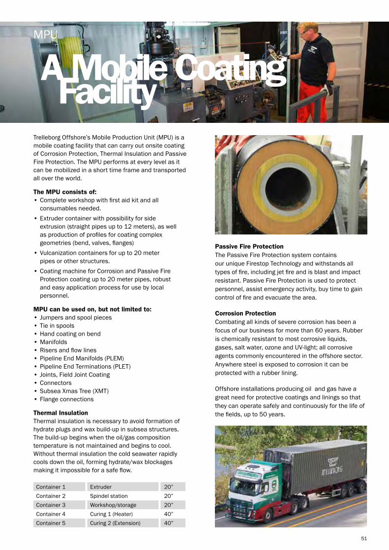
51
Trelleborg Offshore’s Mobile Production Unit (MPU) is a mobile coating facility that can carry out onsite coating of Corrosion Protection, Thermal Insulation and Passive Fire Protection. The MPU performs at every level as it can be mobilized in a short time frame and transported all over the world.
The MPU consists of: • Complete workshop with first aid kit and all consumables needed.• Extruder container with possibility for side extrusion (straight pipes up to 12 meters), as well as production of profiles for coating complex geometries (bend, valves, flanges)• Vulcanization containers for up to 20 meter pipes or other structures.• Coating machine for Corrosion and Passive Fire Protection coating up to 20 meter pipes, robust and easy application process for use by local personnel.
MPU can be used on, but not limited to:• Jumpers and spool pieces• Tie in spools• Hand coating on bend• Manifolds• Risers and flow lines• Pipeline End Manifolds (PLEM)• Pipeline End Terminations (PLET)• Joints, Field Joint Coating• Connectors• Subsea Xmas Tree (XMT)• Flange connections
Thermal Insulation Thermal insulation is necessary to avoid formation of hydrate plugs and wax build-up in subsea structures. The build-up begins when the oil/gas composition temperature is not maintained and begins to cool. Without thermal insulation the cold seawater rapidly cools down the oil, forming hydrate/wax blockages making it impossible for a safe flow.
A Mobile CoatingFacility
MPU
Container 1Container 2Container 3Container 4Container 5
ExtruderSpindel stationWorkshop/storageCuring 1 (Heater)Curing 2 (Extension)
20”20”20”40”40”
Passive Fire Protection The Passive Fire Protection system contains our unique Firestop Technology and withstands all types of fire, including jet fire and is blast and impact resistant. Passive Fire Protection is used to protect personnel, assist emergency activity, buy time to gain control of fire and evacuate the area.
Corrosion Protection Combating all kinds of severe corrosion has been a focus of our business for more than 60 years. Rubber is chemically resistant to most corrosive liquids, gases, salt water, ozone and UV-light; all corrosive agents commonly encountered in the offshore sector. Anywhere steel is exposed to corrosion it can be protected with a rubber lining.
Offshore installations producing oil and gas have a great need for protective coatings and linings so that they can operate safely and continuously for the life of the fields, up to 50 years.

52
Ensuringonboard safety
Vikodeck™
Vikodeck™ has been tested and can withstand cryogenic spills of cold liquids such as LNG and will regain its flexible properties following cryogenic exposure. It is normally delivered in one square meter sheets, but can be can be drilled, cut or shaped to fit the area of installation to suite any surface to provide you with performance at every level.
Safety on offshore oil and gas installations is of paramount importance, and having effective and reliable surface protection is vital to ensuring onboard safety. In the harsh offshore and onshore oil and gas industry, operators need the assurance that their surface protection delivers proven performance for their installations, without fail.
Vikodeck™ is designed to offer surface protection against blast, jet and pool fire in harsh offshore oil and gas environments. It can be tailored to withstand various chemical and mechanical conditions to provide you with performance at every level. In addition it is an excellent corrosion protection and provides anti-fatigue dampening support for the comfort and safety of your employees.
Benefits:
• Abrasion resistant • Blast resistant• Can be painted • Flexible • Maintenance free• No hot work required • Quick and easy to install• Resistant to Ozone and UV light • Seawater resistant • Sound dampening

53
Best rubber pipejoint solutions
Norflex™ Expansion Joints
To prevent breakage on pipelines Trelleborg Applied Technologies Norway offers some of the most flexible ranges of expansion joints. With Norflex™ expansion joints you get the best rubber pipe joint solutions for your connections, tailored to desired lengths.
Benefits: • Tension releasing • Compensate for misalignment• Vibration absorbing • Sound dampening• Compensate for thermal elongation• Ensure a tight seal
Compression
Lateral
Elongation
Angular
The table below contains a range of dimensions related to a standard Norflex™ expansion joint. They can be custom built to different lengths or for different purposes, e.g. for handling vacuum or specifically for low or high working pressure. This will obviously cause some discrepancies in the listed values.
Ny
mm
70
85
100
122
152
176
226
276
330
384
436
488
542
644
746
848
956
1047
1242
T
mm
160
160
180
200
200
200
200
220
230
240
250
280
300
340
360
360
360
360
460
tf
mm
18
18
20
20
22
22
24
26
26
26
32
32
34
36
40
44
48
52
56
k
mm
125
145
160
180
210
240
295
350
400
460
515
565
620
725
840
950
1050
1160
1380
d
mm
18
18
18
18
18
23
23
23
23
23
27
27
27
30
30
33
33
36
36
w/alu. flanges
kg
2
3
4
5
7
8
11
16
18
22
31
37
45
59
75
107
129
152
170
N
mm
50
65
80
100
125
150
200
250
300
350
400
450
500
600
700
800
900
1000
1200
(R)
mm
120
135
165
195
220
25
315
380
430
475
525
580
630
735
850
950
1055
1155
1342
(t)
mm
7
7
9
9
11
11
11
13
15
15
17
17
19
21
21
21
21
21
21
D
mm
165
185
200
220
250
285
340
395
446
505
565
615
670
780
895
1015
1115
1230
1455
n
mm
4
4
4
8
8
8
8
12
12
16
16
20
20
20
24
24
28
28
32
Joint
kg
0,4
1
1,5
2
2,8
3
5
7
8
10
13
16
19
27
29
35
45
50
55
DIN PN10 Weight (ca.)

54
Process deckfire integrity
Drain Gully
To maintain the fire integrity between process deck modules, gaps and openings must be sealed to ensure the safety of onboard personnel during a fire event. Rubber drain gully systems designed by Trelleborg Offshore are installed between deck modules bridging any gap that exists between the structures.
The flexible sealing systems allows for misalignments, angular deviations and eliminate concentrations of stress while reducing vibration and dynamic loads between structures. The systems provide passive fire protection from all types of fires in the extreme offshore operating environments to ensure the safety of people, structures and equipment. While minimizing fire escalation, the rubber sealing systems provide time to evacuate personnel, close down critical equipment and give first responders additional time to gain control of the fire.
The flexible drain gully systems from Trelleborg Offshore are designed to be an alternative to ridged steel gutters onboard platforms and rigs on the process deck and other areas of the platform where the collection of fluids is a requirement. The system is designed to absorb all structural movements and also acts as a drainage system for possible spill and waste runoff from the process area and can be provided as either an open or closed collection system.
Drain gullies can operate as a simple collection system suitable for chemicals, produced waters and rinse water waste and can incorporate blast, jet fire and hydrocarbon pool fire protection as required. The flexible drain gully system is provided in pre-fabricated sections, engineered and designed to meet the exact requirements requested by the customer. They can be installed during the initial platform or rig construction or can be provided as a direct replacement for existing steel gutters. The system is bolted or welded onto offshore structures and can be easily adjusted on site when needed.
Applications: • FPSO• Platforms• Rigs• FLNG
Benefits: • Flexible, durable material• Rated to hydrocarbon and jet fire conditions• Blast, chemical, UV, ozone and saltwater resistant• Maintenance free• 30+ year design life

Flexiblesafety
Escape Tunnel Seal
55
To maintain the fire integrity on an offshore installation during a fire, gaps and openings must be sealed to ensure the safety of onboard personnel. Rubber seal systems designed by Trelleborg Offshore are installed between openings bridging any gap that exists between structures.
The flexible sealing systems allows for misalignments, angular deviations and eliminate concentrations of stress while reducing vibration and dynamic loads between structures. The systems provide passive fire protection from all types of fires in the extreme offshore operating environments to ensure the safety of people, structures and equipment. While minimizing fire escalation, the rubber sealing systems provide time to evacuate personnel, close down critical equipment and give first responders additional time to gain control of the fire.
Escape Tunnel Sealing systems from Trelleborg Offshore provide a flexible joint for escape tunnels between rigid module sections on offshore structures such as rigs and platforms. The system allows structural movement of the escape tunnel between the modules during normal and adverse conditions while absorbing all structural movements. The blast, jet fire and hydrocarbon pool fire resistant system is suited for use on new build structures or during the modification of existing tunnels and is engineered to meet the exact requirements requested by the customer. Each escape tunnel seal can be customized and prefabricated to fit customer specific installations. The system is bolted or welded onto offshore structures and can be easily adjusted on site when needed.
Applications: • FPSO• Platforms• Rigs• FLNG
Benefits: • Flexible, durable material• Rated to hydrocarbon and jet fire conditions• Blast, chemical, UV, ozone and saltwater resistant• Maintenance free• 30+ year design life

56
Flexiblejoints
Linear Seal
To maintain the fire integrity on an offshore installation during a fire, gaps and openings must be sealed to ensure the safety of onboard personnel. Rubber seal systems designed by Trelleborg Offshore are installed between openings bridging any gap that exists between structures.
The flexible sealing systems allows for misalignments, angular deviations and eliminate concentrations of stress while reducing vibration and dynamic loads between structures. The systems provide passive fire protection from all types of fires in the extreme offshore operating environments to ensure the safety of people, structures and equipment. While minimizing fire escalation, the rubber sealing systems provide time to evacuate personnel, close down critical equipment and give first responders additional time to gain control of the fire.
Linear Sealing systems from Trelleborg Offshore provide a flexible joint for any gap between rigid module sections on offshore structures such as rigs and platforms. The Linear seals are constructed using Trelleborg Offshore’s unique multi-layer construction allows for different levels of protection on the inside and outside surfaces of the seals. As the system is flexible, it allows for relative movement between structures during normal and adverse conditions.
The linear seals are engineered to meet the exact requirements requested by the customer and are typically installed in the initial construction phase of the risers to the platform, but can be manufactured to allow for retrofitting on existing platforms. The system is bolted onto offshore structures and can be easily adjusted on site when needed. Linear seals can be rated for blast, jet fire, hydrocarbon pool fire or simply provide a weather resistant seal for operations in extreme conditions.
Applications: • FPSO• Platforms• Rigs• FLNG
Benefits: • Flexible, durable material• Rated to hydrocarbon and jet fire conditions• Blast, chemical, UV, ozone and saltwater resistant• Maintenance free• 30+ year design life

Riser penetrationprotection
Radial Seal
57
To maintain the fire integrity on an offshore installation during a fire, gaps and openings must be sealed to ensure the safety of onboard personnel. Rubber seal systems designed by Trelleborg Offshore are installed between openings bridging any gap that exists between structures.
The flexible sealing systems allows for misalignments, angular deviations and eliminate concentrations of stress while reducing vibration and dynamic loads between structures. The systems provide passive fire protection from all types of fires in the extreme offshore operating environments to ensure the safety of people, structures and equipment. While minimizing fire escalation, the rubber sealing systems provide time to evacuate personnel, close down critical equipment and give first responders additional time to gain control of the fire.
As the steel risers are being routed through the various decks onboard a platform, there is a need to protect the penetration areas to maintain the fire rating of the area. Radial Sealing systems from Trelleborg Offshore provide a flexible joint between the riser and the deck area by attaching to the riser and caisson insuring a tight seal that is both weather and fire rated. The system allows structural movement of the risers during normal and adverse conditions. The radial seals are engineered to meet the exact requirements requested by the customer and are typically installed in the initial construction phase of the risers to the platform, but can be manufactured to allow for retrofitting on existing platforms. The system is bolted or banded onto offshore structures and can be easily adjusted on site when needed. Radial seals can be rated for blast, jet fire, hydrocarbon pool fire or simply provide a weather resistant seal for operations in extreme conditions.
Applications: • FPSO• Platforms• Rigs• FLNG
Benefits: • Flexible, durable material• Rated to hydrocarbon and jet fire conditions• Blast, chemical, UV, ozone and saltwater resistant• Maintenance free• 30+ year design life

58

59
RenewablesFrom cable protection products for the offshore wind sector, to bespoke buoyancy solutions for the wave and tidal sector, Trelleborg Offshore holds a long-standing commitment to serving the renewables market.
Renewable Bend Control Solutions - Where any flexible tubular connects to a structure, normal movement during operation or forces incurred during installation can cause catastrophic failure of the tubular at the termination point. Our bend control solutions reduce this damage.
Renewable Buoyancy - In floating scenarios, pipelines such as cables and umbilicals are often required to be held subsea in specific geometric configurations designed to prevent over utilization of the system.
Renewable Cable and Flowline Protection - With an ever increasing global requirement for data and product transfer, and the necessity for transfer networks to run through ever harsher environments, the demand for highly advanced cable and flowline protection grows.
Renewable Clamping Solutions - A cable laying operation may have a requirement to simultaneously lay a small diameter line. During the installation, to ensure that the secondary lines are adequately supported between surface and seabed, they may be attached to the main pipeline using a clamp arrangement.

60
NjordGuard™ is an innovative protection system designed and developed to protect offshore windfarm power cables in both monopile and J-tube applications.
Benefits:
• Diverless installation and removal• Integrated system, with minimal assembly• Smooth outer surface designed to reduce drag and snagging risk• Utilizes API 17L certified Uraduct® material with class leading impact and abrasion resistance• One design for monopile and J-tube installation• Easily extendable and suitable for any diameter
Diverless Installation and Removal In order to improve safety and reduce installation complexity, NjordGuard™ can be installed, removed, and reused without Remote Operating Vehicles (ROVs) or diver intervention.
Monopile and J-Tube Capable NjordGuard™ design permits both a monopile and J-tube installation for wind turbine generators and offshore substation platforms without procedural variation.
Integrated and Configured for Minimal Assembly Effort NjordGuard™ requires only minimal assembly; the primary external dual stiffener is factory cast directly onto the connector. The internal stiffener can be supplied pre-assembled; only the external tail need be attached with Trelleborg’s novel connection system (patent pending).
Approved Materials
NjordGuard™ uses API 17L certified Uraduct® material for both internal and external components. Uraduct® has an established reputation as the industry standard for cable and flowline protection.
Integratedprotection system
NjordGuard™
Full-scale testing of Trelleborg’s NjordGuard™ integrated protection system
Schematic of NjordGuard™ installation in the monopole
Full-scale NjordGuard ™ installation into a mock monopile, during testing

61
Once the elements lock together the bending moment present is transferred through the elements to a specially designed steel interface structure then into the adjacent rigid connection. To provide the performance at every level, Trelleborg Offshore will design the bend restrictor elements based on supplied information and configure the termination steelwork to suit the project needs.
Benefits:
• A split design allows installation of the restrictor after pipe termination• Ease of installation onshore and offshore• Light weight in water, reducing the loading on the pipe• Increased durability
Where any flexible tubular connects to a structure, normal movement during operation (dynamic loading) or forces incurred during installation and retrieval (static loading) can cause catastrophic failure of the tubular at the termination point. The failure mode can be through collapse, rupture of internal lines or even rupture of the external layers leading to escape of the contents to the environment. This can happen as a result of a single event or be caused through fatigue damage over time.
Bend limiting devices are provided to protect the tubular from these situations and perform the following functions:• Maintain the manufacturers recommended minimum bend radius (MBR) during the life of the project• Provide a suitable load path from tubular to fixed structure• Reduce point loading at the termination to an acceptable level
Bend Restrictors Bend restrictors are used to protect flexible pipelines from overbending and buckling during their installation or operation phase where static loads are generated. The system comprises a number of interlocking elements that articulate in 3 dimensions when subjected to external loads. At a designed radius the elements mechanically lock to form a semi rigid curved structure that will not move further.
A bend limitingdevice
Bend Restrictor
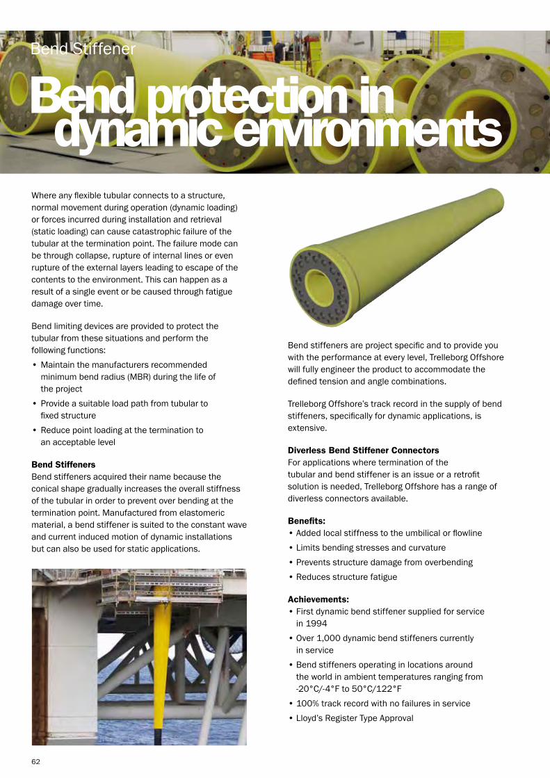
62
Bend stiffeners are project specific and to provide you with the performance at every level, Trelleborg Offshore will fully engineer the product to accommodate the defined tension and angle combinations.
Trelleborg Offshore’s track record in the supply of bend stiffeners, specifically for dynamic applications, is extensive.
Diverless Bend Stiffener Connectors For applications where termination of the tubular and bend stiffener is an issue or a retrofit solution is needed, Trelleborg Offshore has a range of diverless connectors available.
Benefits: • Added local stiffness to the umbilical or flowline• Limits bending stresses and curvature• Prevents structure damage from overbending• Reduces structure fatigue
Achievements: • First dynamic bend stiffener supplied for service in 1994• Over 1,000 dynamic bend stiffeners currently in service• Bend stiffeners operating in locations around the world in ambient temperatures ranging from -20°C/-4°F to 50°C/122°F• 100% track record with no failures in service• Lloyd’s Register Type Approval
Where any flexible tubular connects to a structure, normal movement during operation (dynamic loading) or forces incurred during installation and retrieval (static loading) can cause catastrophic failure of the tubular at the termination point. The failure mode can be through collapse, rupture of internal lines or even rupture of the external layers leading to escape of the contents to the environment. This can happen as a result of a single event or be caused through fatigue damage over time.
Bend limiting devices are provided to protect the tubular from these situations and perform the following functions:• Maintain the manufacturers recommended minimum bend radius (MBR) during the life of the project• Provide a suitable load path from tubular to fixed structure• Reduce point loading at the termination to an acceptable level
Bend Stiffeners Bend stiffeners acquired their name because the conical shape gradually increases the overall stiffness of the tubular in order to prevent over bending at the termination point. Manufactured from elastomeric material, a bend stiffener is suited to the constant wave and current induced motion of dynamic installations but can also be used for static applications.
Bend protection indynamic environments
Bend Stiffener

63
In the subsea environment pipe connections are at risk of corrosion, due to the level of acidity in the water. This corrosion reduces the stability of the pipeline, increasing the likelihood of leakage.
J-Tube Seals are used to prevent the loss of corrosion inhibitor solution used in the annulus between the host line and the J-Tube bore.
Diverless and Modular Design The seal is secured to the host line by integral clamps. It can then be pulled into the J-Tube or I-Tube with the host line. Typically the seal will be installed in the J-Tube just behind the entry bellmouth.
Interference Fit Polyurethance seal elements are used to provide an interference fit to the host line and the J-Tube bore. The interference fit provides the seal – no subsea activation is necessary.
Corrosion Inhibitor Retention J-Tube seals are primarily used to prevent the loss of corrosion inhibitor within the J-Tube annulus.
Key Applications
• J-Tube• Centralized action• Ancillary attachment
Preventing the lossof corrosion inhibitor
J-Tube Seals

64
In the subsea environment ocean currents increase the chance of abrasive damage of supported lines within tubes. Over time this damage could put the connections at risk.
The centralizer’s function is to allow any flexible or rigid line, or multiple lines, to be centered in an I-Tube, J-Tube, tunnel or larger diameter pipe.
Installation Centralizers are installed onto the cable or pipe prior to deployment and pulled in as one unit.
Reduced Pull In Loads Their low coefficient results in reduced installation loads when the line is being pulled in.
Abrasion Protection Centralizers prevent the supported line from touching the inside of the tube into which they are being pulled, preventing abrasion damage.
Key Applications To meet our customers’ needs, our cutting-edge solutions can be used for the below applications:• Cable• Umbilical• Pipeline• Combinations of cables, umbilicals and pipes
Preventingabrasion damage
Subsea Centralizers

65
Minimizing vortexinduced vibration
VIV Suppression Strakes
In deepwater riser applications where the use of steel catenary risers (SCRs) is common, these risers can be introduced to the phenomenon of vortex induced vibration (VIV). This is caused by the regular shedding of vortices from the pipe when subjected to a steady current. The shedding of the vortices can “lock into” the resonant frequency of the pipe along a significant length and can cause the pipe to vibrate. VIV causes accelerated fatigue damage and can give rise to problems such as pipe girth weld failure or premature pipe failure. Other applications prone to VIV are rigid steel flowlines unsupported over free spans and major deepwater field developments requiring a large number of thermally insulated pipelines.
Trelleborg Offshore recognizes that this is an increasingly common problem and therefore, in order to suppress the damaging vibrations to an acceptable level, have put together a comprehensive design package which provides a successful VIV suppression system.
The VIV problem has been analyzed by Trelleborg Offshore using Computational Fluid Dynamics (CFD) software and physical tow tank testing. The results were used to verify the design of the strake concept. Once the suppression strakes are applied, the profile of the VIV strakes practically eliminates periodic vortex shedding from the risers and flowlines. Our VIV suppression strakes are manufactured to order and can accommodate any likely riser or flowline diameter.
To provide you with performance at every level, Trelleborg Offshore offers a range of VIV Suppression Strakes to meet your needs.

66
With an ever increasing global requirement for data and product transfer, and the necessity for transfer networks to run through ever harsher environments, the demand for highly advanced cable and flowline protection grows.
Uraduct® is a protection system designed and developed to protect fiber optic cables, power cables, umbilicals, flexible flowlines, rigid flowlines, hoses and bundled products from abrasion and impact. Uraduct® can also be used to add ballast to cables and flowlines. It has established an enviable reputation as an industry standard for cable and flowline protection.
Benefits: • Easy to handle and transport• Custom made system• Impact and abrasion resistant
Uraduct® + For applications where pipelines or cables are to be subject to high levels of abrasion, Trelleborg developed Uraduct® +, which is considered to be the ultimate protection solution. Flexible pipes, power cables and fiber optic cables can be protected in any area where abrasion is considered to be a problem and stabilization cannot be achieved.
Cable and flowlineprotection
Uraduct®
Uraduct® - Retrofit Riser System With the increasing number of additional cables requiring termination to the offshore platforms and to provide you with performance at every level, Trelleborg designed the Uraduct® Retrofit Riser System, which comprises of Uraduct® and dedicated, high integrity locating clamps.
This system provides a very cost-effective solution where cable entry to a platform is not possible via existing ‘J’ or ‘I’ tubes. Prior to Trelleborg’s Uraduct Retrofit Riser System the only alternative was to install new steel ‘J’ or ‘I’ tubes at great expense, compounded with time consuming and problematic installation.

67
This floating wind turbine project is truly unique. The project, which is being headed up by The Ministry of Economy, Trade and Industry in Japan, will be the world’s largest floating wind farm once complete. Located 16 kilometers off the coast of the Fukushima Daiichi nuclear power plant, it is being developed in wake of the devastating earthquake and tsunami which hit Fukushima in March 2011.
The Fukushima Wind Farm project is a major milestone in the switch from nuclear to renewable for the region. The project, known as Fukushima FORWARD, is part of a bigger scheme to reconstruct the area. Trelleborg supplied the experimental phase one of this pioneering project with its high performance cable buoyancy and protection in 2013 and supplied additional high performance cable protection, for phase two of this prestigious project in 2014.
A pioneering project Trelleborg was awarded the contract to supply the Furukawa Electric Company with its high performance cable buoyancy and protection in 2013, supplying a significant number of Distributed Buoyancy Modules (DBMs), Uraduct, Bend Stiffeners and Bend Restrictors for the experimental phase of this pioneering project.
In floating production scenarios, subsea electrical power cables are used to inter-connect wind turbines on offshore windfarms and also run between the substation (electrical hub of the windfarm) and the shore. Trelleborg’s high performance DBMs are designed to secure, guide and protect these power cables from excessive movement and bending that could cause fatigue damage.
Building on success In the wake of a successful phase one supply, Furukawa Electric once again turned to Trelleborg to supply a range of high performance cable protection, for phase two of this prestigious project.
In floating production environments, subsea electrical power cables are used to inter-connect floating structures on offshore windfarms and also run between the substation (electrical hub of the windfarm) and the shore. Trelleborg’s high performance DBMs are
Protected performancefor floating windfarm
Renewables Application: BEND CONTROL SOLUTIONS
designed to secure, guide and protect these power cables from excessive movement and bending that could cause fatigue damage.
Trelleborg provided its distributed buoyancy modules (DBM), bend stiffeners with dynamic bend stiffener connectors (DBSC), Uraduct™ cable protection and bend restrictors to phase two of the project.
Proving punctual performance The initial project is a five year trial in which different floating structures are tested prior to the main windfarm being constructed, with three floating wind turbines and one floating sub-station being tested as part of the experiment. Following its completion in 2020, it is estimated there will be further floating structures.The initial supply from Trelleborg is for cable buoyancy and protection for the first wind turbine.
This contract was just the latest for Trelleborg within the growing Renewables sector, following on from previous contract wins such as the Statoil Hywind project off the coast of Norway and the Windfloat project off the coast of Portugal. The second phase of this prestigious project depended on working to tight timelines. With the input of Trelleborg’s specialist teams, all products were delivered exactly to schedule and in accordance with Furukawa Electric’s strict deadline.
“Japan is very well suited for the offshore windfarm projects due to its steep coastal shelf and deep water, so it’s extremely encouraging to see that area is fully embracing floating windfarm technology. As a leader in the field, we are confident that Trelleborg is well positioned to take advantage of this rapidly expanding sector.”
John Deasey Renewables Sales Manager at Trelleborg Offshore

68

69
Manufacturing FacilitiesLocal presence, Global reach – Trelleborg Offshore offers teams around the world to meet your requirements.
Email: [email protected] Website: www.trelleborg.com/offshoreTwitter: @offshoreinsightLinkedIn: Trelleborg Offshore

70
Retford, UKAddress: Trinity Park, Randall Way, Retford,
DN22 7AX, UKPhone: +44 (0) 1777 7125001. Our Retford team has proven experience and expertise in solving
our customers’ challenges. Our main focus is design, project management and manufacturing solutions for our customers based on our product and material expertise
2. Office – 760 m²3. Total site – 16,200 m²4. Workshops – 6500 m²5. Testing and R&D – 35 m²6. Storage - 1000 m²
Rochdale, UKAddress: Eagle Way, Off Queensway, Rochdale, Lancashire, OL11 1TQ, UKPhone: +44 (0) 1706 7166101. Established since 1969, Rochdale has proven experience and
expertise in solving our customers’ challenges. Areas of expertise are material development, machining and an ROV center of excellence. The facility operates 3, 5 and 7 axis CNC machine centers and has complimentary finishing facilities for PU, paint and composite coatings.
2. Office - 650 m²3. Total site – 7,081 m²4. Workshops - 3,437 m²
Skelmersdale, UKAddress: Stanley Way, Skelmersdale,
Lancashire, WN8 8EAPhone: +44 (0) 1695 712 0001. Established since 1978, Skelmersdale has proven experience
and expertise in solving our customers’ challenges. Our main focus is in design, project management and manufacturing solutions for our customers based on our product expertise of bespoke composite and plastic solutions.
2. Office – 2,050 m²3. Total site – 52,000 m²4. Workshops – 15,000m²5. Storage - 26,650 m²6. Testing and R&D - 900 m²
Email us on: [email protected] Follow us on: LinkedIn, Twitter, YouTube
Boston, Massachusetts, USAddress: 24 Teed Drive, Randolph, MA 02368Phone: +1 774 719 14001. Established since 1948, Trelleborg Offshore, based in Boston,
has the proven experience and expertise to solve our customers’ challenges. Our areas of expertise include material development and we are an ROV center of excellence. Our main focus is in design, project management and manufacturing solutions for our customers, based on our material expertise.
2. Office – 650 m² 3. Total site – 7,081m²4. Workshops – 3,437m²
Houston, Texas, USAddress: 1902 Rankin Rd, Houston, TX 77073, USAPhone: +1 281 774 26001. Houston’s proven technical capabilities are based on our product
expertise of polymer and syntactic solutions. Our focus as a sales and engineering office is to design solutions to solve our customers’ challenges.
2. Office - 400 m²
Krokstadelva, NorwayAddress: Kalosjegata 15, 3055 Krokstadelva, NorwayPhone: +47 32 23 20 001. With over 120 years of experience our expertise has made us
the largest producer of rubber products and solutions in Norway since the establishment in 1896. We employ dedicated and skilled personnel in the whole value chain. Our main focus is in material development, design, project management and manufacturing tailored solutions for our customer based on their needs.
2. Office – 2,500 m²3. Total site – 25,000 m²4. Workshops – 21,000 m²5. Storage – 1,500 m²
Macaé, BrazilAddress: Rua dos Flutuadores 120, Cabiunas Macaé, RJ, CEP 27970-020 BrazilPhone: +55 22 2106 40401. Opened in 2012 the local site supports the Brazilian oil and gas
supply chain including operators, ship builders, construction contractors and equipment manufacturers. Based in Macaè, the facility has the capability of manufacturing Trelleborg Offshore’s complete product portfolio from topside to seafloor.
2. Office – 390 m²3. Total site – 31,746 m²4. Workshops – 6,150 m²5. Storage - 19,038 m²6. Testing and R&D - 310 m²


Email us on: [email protected] us on: LinkedIn, Twitter, YouTube