Embed Size (px)
Citation preview

Performance-based plastic design of steel plate shear walls
Swapnil B. Kharmale1
Siddhartha Ghosh2, ⁎
Department of Civil Engineering, Indian Institute of Technology Bombay, Mumbai 400076, India
⁎Corresponding author. Tel.: + 91 22 2576 7309; fax: + 91 22 2576 7302.
1Former doctoral research scholar.
2Associate Professor.
Abstract
The existing codes and design guidelines for steel plate shear walls (SPSWs) fail to utilise the excellent ductility capacity of SPSW systems to its fullest extent, because these methods do not consider the inelastic
displacement demand or ductility demand as their design objective. A performance-based plastic design method for SPSW systems with rigid beam-to-column connections is proposed in this work, which sets a specific ductility
demand and a preferred yield mechanism as its performance targets. The effectiveness of the proposed method in achieving these targets is illustrated through sample case studies of four- and eight-storey SPSW systems for
varied design scenarios. A comparison with the existing AISC method for the same design scenario shows that the proposed method consistently performs better, in achieving these performance-based targets. The proposed
method is modified to account for P-Delta effects, wherever necessary. This modified method is found to be more effective than the original proposal, whenever P-Delta effects are significant.
Keywords: Steel plate shear wall; Performance-based design; Inelastic deformation capacity; Ductility-based design; P-Delta effects
1 IntroductionExisting design provisions for steel plate shear walls
During the 1980s and 1990s, a significant amount of research works, both ‘analytical’ and ‘experimental’, was conducted on the post-buckling behaviour of thin unstiffened steel plate shear wall (SPSW) systems [1]. These research
works, conducted primarily in Canadian and U.S. universities (for example, [2–6]), resulted in the incorporation of design specifications for SPSW systems in design standards/codes. In 1994, the Canadian steel design standard [7] included
design provisions for unstiffened thin SPSW, although only as an appendix to the main design code. The 2001 Canadian standard [8] incorporated mandatory clauses on the design of steel plate shear walls. This standard had provisions for
both ‘limited ductility’ and ‘ductile’ steel plate shear walls. For the limited ductility SPSW, no special requirements were made for the beam-to-column connections and a response modification factor (R) of 2.0 was assigned for these systems.
For the ductile SPSW, however, the beam-to-column connections had to be moment resisting and the response modification factor was higher (R = 5.0). In order to ensure a ductile failure mode for SPSW structures, this code recommended
an indirect capacity design approach. In this approach, a factor B (ratio of the probable shear resistance at the base of the wall for a given plate thickness to the factored lateral force at the base of the wall, obtained from the calculated
seismic load) was used to magnify the moments and axial forces in columns obtained from an elastic analysis. This magnification was not required if column forces and moments were obtained from a nonlinear pushover analysis. Further
research on SPSW systems in the last decade, particularly the plastic analysis and design methods for SPSW [9], resulted in newer design provisions, for example, as in the AISC Seismic Provisions [10,11] and the Canadian standard
CAN/CSA S16 [8,12].
The AISC SPSW specifications followed the load and resistance factor design (LRFD) format based on the limit state of collapse. The concept of capacity design was incorporated in this standard. For example, all edge/boundary
elements (‘horizontal boundary elements/HBE’ and ‘vertical boundary elements/VBE’) were designed to resist the maximum forces that could be generated by fully yielded steel ‘infill panels’. These provisions also indicated to a preferred
mechanism of failure through specifications, such as that the boundary elements were required to be proportioned in order to meet the ‘strong-column-weak-beam’ criterion, and that in boundary elements plastic hinging was permitted only at
HBE ends. The recently published AISC Design Guide 20 for SPSW [13] developed the 2005 AISC Seismic Provisions into a complete design methodology. It included step-by-step design procedures as well as design examples for two
types of steel plate shear walls: high-ductility SPSW (with R = 7.0) for high-seismic regions and low-ductility SPSW (with R = 3.0) for low seismic regions. This design guide was developed in accordance with the then existing relevant
standards ASCE7-05 for minimum design loads in buildings [14], ANSI/AISC 360-05 for structural steel [15], and 2005 AISC Seismic Provisions [10].

standards ASCE7-05 for minimum design loads in buildings [14], ANSI/AISC 360-05 for structural steel [15], and 2005 AISC Seismic Provisions [10].
Although elements of capacity design concepts were incorporated in the latest Canadian and U.S. steel design standards, there are a few limitations when assessed from a performance-based seismic design (PBSD) perspective
1. Significant inelastic deformation capacity (ductility) of SPSW systems cannot be fully utilised by these codes, as the design is primarily based on an elastic force/strength-based approach where the inelastic behaviour is implicitly accounted for through a response modification factor, R.
2. These guides specify a desirable yield mechanism, however they do not provide specific design equations to attain this yield mechanism [16], especially for the VBE and HBE in the SPSW system.
3. These standards do not provide the designer any option to choose a specific yielding hierarchy or failure mechanism for the SPSW structure.
In more recent times, Berman and Bruneau [17] proposed a reasonably accurate and relatively effective capacity design method for SPSW columns (VBE). Their procedure combined a linear elastic model of SPSW and plastic
analysis concepts. Research works by [18–21] provided capacity design provisions for boundary beams (HBE) in SPSW systems. These design equations, especially those for ‘anchor beams’ (beams at roof and ground level with infill panels
only at one side) were derived considering local collapse mechanism (‘beam mechanism’) with plastic hinges forming at the ends of the HBE and close to the mid-span of the HBE. Vian et al. [19] also recommended the use of ‘reduced beam
section/RBS’ at the ends of the HBE to ensure the preferred failure mechanism of the AISC Seismic Provisions.
Over the last decade, the performance-based seismic design philosophy has emerged as a promising and efficient seismic design approach. PBSD explicitly accounts for the inelastic behaviour of a structural system in the design
process itself. PBSD approaches based on plastic analysis and design concepts called as performanceperformanc-based plastic design (PBPD) methods were recently developed for different lateral load resisting systems (such as steel
moment resisting frames, steel braced frames, etc.) in the University of Michigan [22,23]. In these design methods a pre-selected yield/failure mechanism and a uniform target drift (based on inelastic behaviour) were considered as
performance objectives. The analytical validation of these methods showed that structures designed using these methods were very effective in achieving the pre-selected performance objectives. Details of these methods and step-by-step
procedures were later compiled in a book by Goel and Chao [24]. Considering a gradual shift towards PBSD for seismic design methods in general, Ghosh et al. [25] proposed a displacement/ductility-based design methodology for steel plate
shear wall systems with pin-connected boundary beams. Similar to the methods developed in the University of Michigan, they also considered the target displacement ductility ratio and a pre-selected yield mechanism as the design criterion;
and an inelastic energy balance concept was used in the formulation of the design method. Ghosh et al. validated this method by designing a four-storey SPSW with pin-connected beams subjected to various ground motion scenarios and for
different target ductility ratios. Gupta et al. [26] successfully applied the inelastic displacement ductility-based method proposed by Ghosh et al. using standard hot rolled-sections (for boundary elements) available in the U.S. [15] and in India
[27]. More recently, while investigating for a suitable (height-wise) distribution of the design base shear for this method, [28] applied this method effectively to SPSW with pin-connected beams of various heights.
2 Objective
Considering that the existing U.S. and Canadian design standards/guides for ‘ductile’ SPSW recommend the use of only rigid beam-to-column connections, an inelastic displacement-based seismic design method similar to that
proposed by Ghosh et al. [25] needs to be formulated for SPSW systems with rigid beam-to-column connections. The primary objective of the work presented here, thus, is to develop a PBPD method for SPSW systems with rigid beam-to-
column connections, with the following performance goals:
1. achieving a target displacement ductility ratio demand considering the inelastic behaviour of the SPSW system, and
2. achieving a pre-selected yield/failure mechanism for this inelastic behaviour.
It must be mentioned here that in order to develop a full-fledged PBSD framework for any structural system, the first important task is to define acceptable performanceperfromance levels in a specific quantitative manner in terms of
structural, non-structural and component behaviours. The focus of this work, however, is on the structural design calculations once a performance level is selected and limits are defined in terms of displacement-based quantities. Before we
begin with the proposal of a PBPD method for SPSW, the existing design method (based on AISC Design Guide 20) is reviewed through a sample design case and it is checked if this sample design meets the stated performance objectives
(Section 3). Section 4 provides the fundamentals and the framework of the proposed PBPD method for SPSW with rigid beam-to-column connections. This method is validated in Section 5 through sample designs of low-rise (four-storey) and
medium-rise (eight-storey) SPSW buildings, for different target ductility ratios, and subjected to various earthquake scenarios. Results of this validation are discussed in detail, along with a comparison with the sample design based on
existing AISC guidelines. A modification of the proposed PBPD method – to account for P-Delta effects (which are predominant for medium- and high-rise SPSW systems with large displacement ductility demands) – is provided in Section 6.
Section 7 presents the significant conclusions of this work and also discusses the limitations thereof. It should however, be noted that the work presented here does not address the issue of formulating the design method in a probabilistic
framework, which is the most significant feature for a PBSD methodology, other than the explicit consideration of inelastic behaviour and damage in a structure. We are currently engaged in developing a reliability-based framework for the
performance-based plastic design method, which will be reported in future.
3 Design of a SPSW system following AISC Design Guide 20, and its performance assessment
Kharmale and Ghosh

3 Design of a SPSW system following AISC Design Guide 20, and its performance assessment
To assess the seismic performance of a steel plate shear wall structure, which is designed following provisions of AISC Design Guide 20 [13], a four-storey steel plate shear wall building is considered. The configuration of this four-
storey building is illustrated in detail in Fig. 1. The building has a five bay by six bay plan, with one SPSW bay along each outer frame. All beams, except those in the SPSW bays, are pin-connected (shear-connected) to the frame, and
therefore only the SPSW frames form the lateral load resisting system. The building is assumed to have seismic weights of 4690 kN per floor, except for the roof, where it is 5090 kN. For seismic force calculations, this study building is
assumed to be located in downtown San Francisco, CA, USA. The building site is categorised as Site Class D for ‘stiff soil’ and the its occupancy category is adopted as ‘I’, based on its use as an office building. The site location and the soil
characteristics considered here are the same as those that of the design example II (‘high-seismic’ design) provided in AISC Design Guide 20 [13].
As mentioned earlier, the seismic force calculations in AISC Design Guide 20 are based on ASCE7 [14], where the inelastic behaviour of a structure is only implicitly accounted for through a response modification/reduction factor, R.
For the design of SPSW systems subjected to a ‘high seismic’ scenario, ASCE7 specifies a response modification factor, R = 7.0 and a system overstrength factor, Ω0 = 2.0. These values were later supported by a detailed numerical study
on 44 SPSW designs [29]. Assuming that the structure under consideration does not have any supplemental damping device and also adopting a minimum reliability factor, one can conclude that SPSW systems are designed for a target
displacement ductility ratio, µ = 3.5. It should be noted here that ASCE7 and AISC Design Guide 20 do not directly include the displacement ductility ratio of a system in the calculation of the design base shear. The MCE spectral
accelerations for this location are, SS = 1.70 g and S1 = 0.850 g. Following ASCE7, the design spectral acceleration parameters are calculated: SDS = 1.14 g and SD1 = 0.850 g. The design base shear is calculated as 3120 kN following ASCE7
guidelines. The different components of the SPSW system are designed as per the AISC Design Guide 20 and the AISC Seismic Provisions. Here onwards, this design is referred to as the ‘AISC method’ design. The final dimensions of
various components and other features of this design are
• Infill panel thickness (from the first storey upwards) = 5.50, 5.00, 4.00, and 2.30 mm.
• HBE (same section for all floors) = W 27 × 94
• VBE (same section for all storeys) = W 14X × 398
• Fundamental time period (T1), estimated as per ASCE7 = 0.585 s
• Spectral acceleration for T1 (Sa) = 1.14 g.
As per the design specifications, the displacement ductility (ratio) demand for this structure subjected to a design level earthquake should ideally be 3.50, which will exploit the capacity to the fullest without overshooting it. The
seismic performance assessment for this structure is based on this perspective. This ductility demand (µd) is evaluated using nonlinear response history analyses (NLRHA) subjected to real earthquake records. Three strong motion records
(Table 1), scaled to the design Sa of this typical design, are used in these NLRHA. The ductility ratio demand is calculated as
Fig. 1 Configuration of the hypothetical study building(s).
(1)

where, Dm is the maximum roof displacement obtained from an NLRHA and Dy is the yield roof displacement. Dy for a SPSW structure is obtained from the conventional nonlinear static pushover analysis (NSPA) using the lateral load
distribution recommended in the IBC [30]. The base shear (Vb) vs. roof displacement (D) pushover plot is bilinearized using an elastic-perfectly plastic force-deformation behaviour so that the areas under the pushover curve and its bilinear
approximation are equal (Fig. 2). FromForm the NSPA, the yield displacement (Dy) is obtained as 0.123 m, with a yield base shear of 3892 kN. The three earthquakes result in µd values of 2.36, 2.18 and 1.76 (giving an average of 2.10). These
values show that the existing design method do not (always) utilise the excellent displacement capacity of SPSW systems. The three different earthquakes result in very different yielding patterns. The lack of an effective energy dissipation
through inelastic activity is also evident from the fact that beams do not form plastic hinges at both ends. Besides, the plasticity is observed to be concentrated more in the second and third storeys, resulting in higher interstorey drift (ratio)
demands in these two than the other storeys. Fig. 3 provides the displacement profile for this design at the instant of peak roof displacement for each of the three records, along with an ‘ideal’ response based on the ductility factor.
Table 1 Details of earthquake records used for designs of four-storey and eight-storey SPSWs.
Earthquake Date Station Component PGA (g) Name
Northridge Jan 17,1994 Sylmar converter Horizontal -052 0.612 SYL
Northridge Jan 17, 1994 Newhall fire station Horizontal - 360 0.589 NH
Kobe Jan 16, 1995 KJMA Horizontal - 000 0.821 KJM
Landers Jun 28, 1992 SCE station 24 Horizontal -000 0.785 LAN
Imperial Valley Oct 15, 1979 USGS station 5054 Horizontal -140 0.775 IMV
Cape Mendocino Apr 25,1992 CDMG station 89005 Horizontal- 000 1.497 CM
(1)
Fig. 2 Obtaining the yield base shear (Vy) and yield displacement (Dy) from the bilinearized pushover plot.

4 Proposed performance-based design methodology
The proposed performance-based design method broadly follows the performance-based plastic design methodology recommended by [24] for various other lateral load resisting systems in steel. As mentioned earlier, the proposed
design method considers a uniform interstorey drift ratio and a pre-selected yield mechanism as performance targets. Fig. 4 shows a typical one-bay SPSW configuration with rigid beam-to-column connections, along with the selected
unidirectional and uniform yield mechanism. This preferred yield mechanism consists of the yielding of all steel infill panels, formation of plastic hinges at the column bases, and formation of plastic hinges at the two ends of each beam
(HBE). Capacity design approaches proposed earlier for SPSW systems also specify this as the desired yield mechanism.
Fig. 3 Displacement profiles for the ‘AISC method’ design SPSW system, at the instant of maximum roof displacement.

The proposed design method adopts the concept of energy balance, in which the inelastic energy demand on a structural system is equated with the inelastic work done, internally, through the plastic deformations. The total strain
energy demand to an inelastic single-degree-of-freedom (SDOF) system is estimated as
where, Ee = elastic strain energy demand, Ep = plastic strain energy demand, γ = energy modification factor, M = total seismic mass of the structure, Sv = spectral velocity corresponding to T1, and Ce = elastic force coefficient. Based
on the study by Akiyama [31], the elastic vibrational energy can be written, assuming that the entire structure is reduced into a SDOF system:
W is the total seismic weight of the structure and Vb is the base shear. The energy modification factor (γ) comes from the equal displacement law, and is calculated based on the target displacement ductility ratio of the system (µt)
and the ductility-based reduction factor (Rµ):
Any suitable ‘R–µ–T’ relation can be used to estimate Rµ. Here, we use the relationships suggested originally by Newmark and Hall [32]. Based on recent findings [33], the effects of material strain-hardening are neglected in this work,
although the proposed method can be easily modified to incorporate this aspect. The elastic force coefficient is expressed in terms of the design pseudo- acceleration (Sa) or the design yield base shear (Vby), as
The structure is idealised as an elastic-perfectly plastic (EPP) equivalent single degree system by selecting the preferred yield mechanism up to the peak monotonic drift demand (Fig. 4). The elastic part of the total strain energy
demand is calculated by replacing Vb with the yield base shear (Vby) in Eq. (3). Substituting this in Eq. (2), we get
This plastic energy demand is the same as the work done by the equivalent lateral forces Fi (Fig. 4) going through the inelastic drift (θp):
Fig. 4 (a) Schematic of a SPSW system with rigid beam-to-column connections; and (b) the selected uniform and unidirectional yield mechanism.
(2)
(3)
(4)
(5)
(6)
(7)
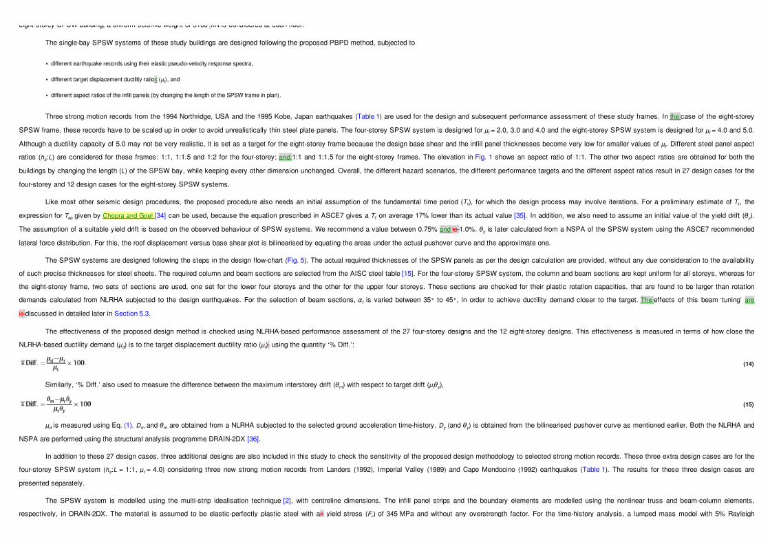
where, hi is the height of ith floor measured from the ground, and Cvi is the lateral force distribution factor for this floor. Recent research by Kharmale and Ghosh [28] recommended that any commonly followed lateral force distribution
(that is, Cvi) can be adopted in the inelastic displacement-based design method for SPSW systems. In this work, the distribution recommended by ASCE7 is adopted. Eq. (7) can be rearranged in the form of a quadratic equation and its
solution provides an expression for the required yield base shear for this performance-based design:
Once Vby is obtained, a preliminary design of the steel infill panels is considered first. Assuming that each infill panel takes the full storey shear (Vi), the initial thickness of the panel at the ith storey (t′) is obtained, similarly as by
Ghosh et al. [25]:
where, Fy is the material yield stress and L is the infill panel width. The selection of the column section is primarily based on the minimum (strength and) stiffness requirement prescribed in the Canadian standard [8] and the AISC
Seismic Provisions [10], which ensures that there will be no premature buckling of a column under the pulling action of the infill plate:
where, Ici is the moment of inertia of the ith storey column about its bending axis, and hsi is the ith interstorey height. The floor beams are designed in order to properly anchor the panel tension fields. The SPSW system is assumed
to have rigid floor diaphragms at all floor levels due to the existence of a composite steel deck. The assumption of a rigid floor diaphragm results in zero axial force in all floor beams. The selection of the beam section is an iterative procedure
which involves the assumption of the angle of tension field (αt) in the steel plate panel and the successive calculation of the beam cross-sectional area. The following expression, suggested by Timler and Kulak [3] for αt in the ith storey infill,
is used to calculate the beam area required:
where, Abi and Aci are the cross-sectional areas of the boundary beams and columns, respectively. Although this equation was originally developed for SPSW with pinned beam-to-column connections, it can also be used for SPSW
with rigid beam-to-column connections, since the value of αt is not really sensitive to the flexural stiffness of boundary beams [13].
In order to update the infill panel thicknesses, the virtual work principle is used by equating the inelastic work done by the equivalent forces (Fi) with the inelastic work done in the plates and in the plastic hinges in boundary elements.
The plastic deformations, in this case, are obtained from a unidirectional monotonic loading up to the target drift. The formation of plastic hinges and the yielding of infill plates are assumed to occur simultaneously, at an yield drift θy. The
required shear capacity of the plate (Pi) at the ith storey is obtained from the following equation:
where, n is the number of storeys in the structure, Mpc is the plastic moment capacity at each column base, and Mpbi is the plastic moment capacity of the ith floor beam. The revised plate thickness is obtained as
The design axial force (Pc) on the columns is calculated based on the moment equilibrium about the base. The final column section is then selected from a steel table (for example, the AISC steel table [15]) for these demands on the
basis of the code prescribed ‘P–-M interaction’ and compact section criterion. This design is checked for if the demand (µd) is satisfactorily close to the target (µt). Otherwise, the HBE dimensions are changed and the plate thicknesses are
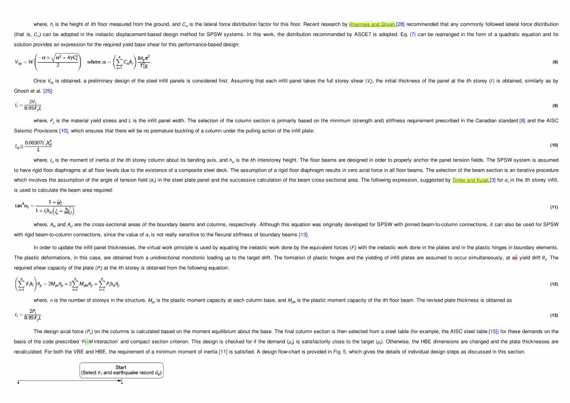
recalculated. For both the VBE and HBE, the requirement of a minimum moment of inertia [11] is satisfied. A design flow-chart is provided in Fig. 5, which gives the details of individual design steps as discussed in this section.
(8)
(9)
(10)
(11)
(12)
(13)

5 Validation of the proposed design method
The proposed performance-based design methodology for SPSW systems is validated through the design and the following performance assessment of one four-storey and one eight-storey SPSW systems. These two buildings are
selected to represent typical symmetric-in-plan low-rise and medium-rise office buildings. Both buildings have the same plan configuration, including the location of the SPSW bay in the outer frames of the building (Fig. 1). Their elevations are
also the same except for that the eight-storey frame has four similar additional storeys. For the four-storey building, the floor-wise seismic weights are the same as those for the ‘AISC method’ design building considered in Section 3. For the
eight-storey SPSW building, a uniform seismic weight of 5160 kN is considered at each floor.
Fig. 5 Flowchart for the proposed performance-based plastic design of SPSW systems with rigid beam-to-column connections.
eight-storey SPSW building, a uniform seismic weight of 5160 kN is considered at each floor.
The single-bay SPSW systems of these study buildings are designed following the proposed PBPD method, subjected to
• different earthquake records using their elastic pseudo-velocity response spectra,
• different target displacement ductility ratios (µt), and
• different aspect ratios of the infill panels (by changing the length of the SPSW frame in plan).
Three strong motion records from the 1994 Northridge, USA and the 1995 Kobe, Japan earthquakes (Table 1) are used for the design and subsequent performance assessment of these study frames. In the case of the eight-storey
SPSW frame, these records have to be scaled up in order to avoid unrealistically thin steel plate panels. The four-storey SPSW system is designed for µt = 2.0, 3.0 and 4.0 and the eight-storey SPSW system is designed for µt = 4.0 and 5.0.
Although a ductility capacity of 5.0 may not be very realistic, it is set as a target for the eight-storey frame because the design base shear and the infill panel thicknesses become very low for smaller values of µt. Different steel panel aspect
ratios (hs:L) are considered for these frames: 1:1, 1:1.5 and 1:2 for the four-storey; and 1:1 and 1:1.5 for the eight-storey frames. The elevation in Fig. 1 shows an aspect ratio of 1:1. The other two aspect ratios are obtained for both the
buildings by changing the length (L) of the SPSW bay, while keeping every other dimension unchanged. Overall, the different hazard scenarios, the different performance targets and the different aspect ratios result in 27 design cases for the
four-storey and 12 design cases for the eight-storey SPSW systems.
Like most other seismic design procedures, the proposed procedure also needs an initial assumption of the fundamental time period (T1), for which the design process may involve iterations. For a preliminary estimate of T1, the
expression for Teq given by Chopra and Goel [34] can be used, because the equation prescribed in ASCE7 gives a T1 on average 17% lower than its actual value [35]. In addition, we also need to assume an initial value of the yield drift (θy).
The assumption of a suitable yield drift is based on the observed behaviour of SPSW systems. We recommend a value between 0.75% and to 1.0%. θy is later calculated from a NSPA of the SPSW system using the ASCE7 recommended
lateral force distribution. For this, the roof displacement versus base shear plot is bilinearised by equating the areas under the actual pushover curve and the approximate one.
The SPSW systems are designed following the steps in the design flow-chart (Fig. 5). The actual required thicknesses of the SPSW panels as per the design calculation are provided, without any due consideration to the availability
of such precise thicknesses for steel sheets. The required column and beam sections are selected from the AISC steel table [15]. For the four-storey SPSW system, the column and beam sections are kept uniform for all storeys, whereas for
the eight-storey frame, two sets of sections are used, one set for the lower four storeys and the other for the upper four storeys. These sections are checked for their plastic rotation capacities, that are found to be larger than rotation
demands calculated from NLRHA subjected to the design earthquakes. For the selection of beam sections, αt is varied between 35° to 45°, in order to achieve ductility demand closer to the target. The effects of this beam ‘tuning’ are
is discussed in detailed later in Section 5.3.
The effectiveness of the proposed design method is checked using NLRHA-based performance assessment of the 27 four-storey designs and the 12 eight-storey designs. This effectiveness is measured in terms of how close the
NLRHA-based ductility demand (µd) is to the target displacement ductility ratio (µt). using the quantity ‘% Diff.’:
Similarly, ‘% Diff.’ also used to measure the difference between the maximum interstorey drift (θm) with respect to target drift (µtθy),
µd is measured using Eq. (1). Dm and θm are obtained from a NLRHA subjected to the selected ground acceleration time-history. Dy (and θy) is obtained from the bilinearised pushover curve as mentioned earlier. Both the NLRHA and
NSPA are performed using the structural analysis programme DRAIN-2DX [36].
In addition to these 27 design cases, three additional designs are also included in this study to check the sensitivity of the proposed design methodology to selected strong motion records. These three extra design cases are for the
four-storey SPSW system (hs:L = 1:1, µt = 4.0) considering three new strong motion records from Landers (1992), Imperial Valley (1989) and Cape Mendocino (1992) earthquakes (Table 1). The results for these three design cases are
presented separately.
The SPSW system is modelled using the multi-strip idealisation technique [2], with centreline dimensions. The infill panel strips and the boundary elements are modelled using the nonlinear truss and beam-column elements,
respectively, in DRAIN-2DX. The material is assumed to be elastic-perfectly plastic steel with an yield stress (Fy) of 345 MPa and without any overstrength factor. For the time-history analysis, a lumped mass model with 5% Rayleigh
(14)
(15)

respectively, in DRAIN-2DX. The material is assumed to be elastic-perfectly plastic steel with an yield stress (Fy) of 345 MPa and without any overstrength factor. For the time-history analysis, a lumped mass model with 5% Rayleigh
damping (in the first two modes) is considered. Effects of geometric nonlinearity and the nominal lateral stiffness offered by the gravity frames are neglected. The hysteretic behaviour of the structure is assumed to be stable without
strength/stiffness degradations and pinching [37].
5.1 Summary of results for the four-storey SPSW designs
Tables 2–4 present the summary of results for the 27 designs of the four-storey SPSW system. Each design is identified here with the specific earthquake record and the target displacement ductility ratio it is designed for. For each design, Dy, Dm and
θm values are also presented in these tables. However, the most important data in these tables are in the ‘% Diff.’ columns, which give a measure of the effectiveness of the proposed design method. The mean (‘Average’) and the absolute maximum
(‘AbsMax’) values of % Diff. for all design scenarios belonging to a specific steel panel aspect ratio are also provided in these tables.
Table 2 Results summary for designs of four-storey SPSW systems having hs:L = 1:1.
Design Record µt Dy (m) Dm (m) µd % Diff. µtθy θm % Diff.
I SYL 2 0.103 0.212 2.06 3.00 0.0129 0.0160 24.3
II SYL 3 0.0987 0.300 3.04 1.33 0.0185 0.0190 2.67
II SYL 4 0.107 0.418 3.89 −– 2.75 0.0268 0.0281 4.67
IV NH 2 0.103 0.220 2.13 6.50 0.0129 0.0150 16.5
V NH 3 0.0912 0.270 2.96 −– 1.33 0.0171 0.0159 −– 6.43
VI NH 4 0.0910 0.334 3.89 −– 2.75 0.0228 0.0250 9.89
VII KJM 2 0.100 0.220 2.19 9.50 0.0125 0.0160 28.0
VIII KJM 3 0.0957 0.290 3.03 1.00 0.0179 0.0140 −– 22.0
IX KJM 4 0.0963 0.343 3.56 −– 11.0 0.0241 0.0242 0.312
Average −– 1.85 6.37
AbsMax 11.0 28.0
Table 3 Results summary for designs of four-storey SPSW systems having hs:L = 1:1.5.
Design Record µt Dy (m) Dm (m) µd % Diff. µtθy θm % Diff.
X SYL 2 0.0863 0.182 2.11 5.50 0.0108 0.00901 − 16.6
XII SYL 3 0.0829 0.248 2.99 − 0.333 0.0155 0.0169 9.37
XII SYL 4 0.0745 0.301 4.04 1.00 0.0186 0.0180 − 3.36
XIII NH 2 0.0894 0.169 1.89 − 5.50 0.0112 0.0120 7.38
XIV NH 3 0.0855 0.260 3.04 1.33 0.0160 0.0150 − 6.43
XV NH 4 0.0744 0.276 3.71 − 7.25 0.0186 0.0190 2.15
XVI KJM 2 0.0902 0.193 2.14 7.00 0.0113 0.0100 − 11.3
XVII KJM 3 0.0957 0.287 3.00 0.000 0.0179 0.0160 − 10.8
XVIII KJM 4 0.0833 0.330 3.96 − 1.00 0.0208 0.0220 5.64
Average 0.0833 − 2.66
AbsMax 7.25 16.6

Table 4 Results summary for designs of four-storey SPSW systems having hs:L = 1:2.
Design Record µt Dy (m) Dm (m) µd % Diff. µtθy θm % Diff.
XIX SYL 2 0.078 0.152 1.94 − 3.00 0.00980 0.00900 − 8.16
XX SYL 3 0.081 0.235 2.92 − 2.67 0.0151 0.0160 6.00
XXI SYL 4 0.080 0.302 3.76 − 6.00 0.0201 0.0200 − .535
XXII NH 2 0.075 0.155 2.06 3.00 0.00940 0.0100 6.38
XXIII NH 3 0.082 0.242 2.94 − 2.00 0.0154 0.0130 − 15.8
XXIV NH 4 0.076 0.300 3.96 − 1.00 0.0189 0.0170 − 10.3
XXV KJM 2 0.084 0.168 1.99 − 0.500 0.0105 0.00900 − 14.7
XXVI KJM 3 0.074 0.218 2.95 − 1.67 0.0139 0.0120 − 13.4
XVIII KJM 4 0.074 0.290 3.93 − 1.75 0.0184 0.0170 − 7.86
Average − 1.73 − 7.01
AbsMax 6.00 15.8
For µd, the mean % Diff. is found to be 0.389, 0.0833 and −- 1.73, and for θm this mean is found to be 6.37, −- 2.66 and −- 7.01, for aspect ratios (hs:L) of 1:1, 1:1.5 and 1:2, respectively. The corresponding values of AbsMax are 11.0, 7.25 and 6.00 for µd
and 28.0, 16.6 and 15.8. These very low average and AbsMax values clearly show that the proposed design method is able to achieve its performance targets very efficiently (specifically for the roof displacementdispacement ductility ratio). The accuracy is
slightly on the lower side for achieving the target interstorey drift ratio. It is also evident from these results that this efficiency is maintained for different ground motion records, different target ductility ratio values (µt), and for different steel panel aspect ratios. In
addition to the ductility demand in terms of the peak roof displacement, the displacement profiles are also studied in order to check for any localised concentration of plasticity in any storey. Fig. 6 presents displacement profiles at the instant of peak roof drift for
all nine design cases with hs:L = 1:1. These displacement profiles demonstrate an almost uniform distribution of the interstorey drift over the height. Similar displacement profiles are also observed for the other 18 design cases belonging to hs:L = 1:1.5 and 1:2.
This indicates that the structure closely follows the assumed yield mechanism with uniform interstorey drift along the height, and there is no severe concentration of plasticity in any specific storey.

The results summary for the additional three design cases (Designs XXVIII, XXIX and XXX, for three other earthquakes) is are presented in Table 5. The mean and the AbsMax of the values of % Diff. for µd are −- 1.73 and 6.00, and for θm are −- 4.41
and 9.28, respectively. These values show that the proposed method remains effective for these earthquakes as well, which indicates the robustness of the proposed method subjected to a variety of strong motion records.
Table 5 Results summary for designs considering three additional records.
Design Record µt Dy (m) Dm (m) µd % Diff. µtθy θm % Diff.
XXVIII LAN 4 0.0970 0.354 3.65 − 8.75 0.0243 0.0220 − 9.28
XXIX IMV 4 0.101 0.362 3.58 − 10.5 0.0252 0.0242 − 3.96
XXX CM 4 0.096 0.357 3.74 − 6.50 0.0240 0.0240 0.000
Average − 1.73 − 4.41
AbsMax 6.00 9.28
5.2 Summary of results for the eight-storey SPSW designs
The results for the 12 eight-storey designs are presented in a similar (to that of the four-storey designs) manner in Tables 6–7-. These tables also provide the scale factor applied to the original acceleration record for each individual design. These
same scaled ground motion records are used in their performance assessment. Considering roof displacement ductility as performance objective, the average % Diff. values are observed to be −- 7.32 and −- 2.03 for steel panel aspect ratios of 1:1 and 1:1.5,
respectively, and the corresponding values of AbsMax are 15.0 and 5.80. The average % Diff. values for θm are −- 0.353 and −- 5.54 for steel panel aspect ratios of 1:1 and 1:1.5, respectively, and the corresponding values of AbsMax are 17.2 and 18.5. These
results show that the proposed method is equally effective for medium-rise SPSW systems, as well. Fig. 7 presents displacement profiles at the instant of peak roof drift for all the six design cases with hs:L = 1:1. These profiles show that system follows nearly
the same deformation profile as assumed in the design formulation, and that there is no concentration of damage in any specific storey.
Table 6 Results summary for designs of eight-storey SPSW systems having hs:L = 1:1.
Design Record µt Scale factor Dy (m) Dm (m) µd % Diff. µtθy θm % Diff.
I SYL 1.20 4 0.247 0.985 3.99 − 0.250 0.0308 0.0340 10.1
II SYL 1.30 5 0.234 1.08 4.61 − 7.80 0.0365 0.0400 9.41
III NH 1.30 4 0.232 0.837 3.61 − 9.75 0.0290 0.0240 − 17.2
IV NH 1.50 5 0.219 1.03 4.72 − 5.60 0.0342 0.0318 − 6.85
V KJM 1.40 4 0.208 0.786 3.78 − 5.50 0.0260 0.0250 − 3.85
VI KJM 1.90 5 0.238 1.01 4.25 − 15.0 0.0372 0.0390 4.87
Average − 7.32 − 0.353
AbsMax 15.0 17.2
Fig. 6 Displacement profiles of the four-storey designs with hs:L = 1:1, at the instant of maximum roof displacement.

AbsMax 15.0 17.2
Table 7 Results summary for designs of eight-storey SPSW systems having hs:L = 1:1.5.
Design Record µt Scale factor Dy (m) Dm (m) µd % Diff. µtθy θm % Diff.
VII SYL 1.20 4 0.226 0.867 3.84 − 4.00 0.0282 0.0230 − 18.6
VIII SYL 1.30 5 0.192 0.962 5.00 0.000 0.0300 0.0290 − 3.33
IX NH 1.30 4 0.218 0.881 4.04 1.00 0.0272 0.0280 2.75
X NH 1.50 5 0.194 0.954 4.92 − 1.60 0.0303 0.0270 − 11.0
XI KJM 1.40 4 0.177 0.697 3.93 − 1.75 0.0221 0.0200 − 9.61
XII KJM 1.90 5 0.171 0.805 4.71 − 5.80 0.0267 0.0240 − 10.2
Average − 5.54 − 2.03 − 5.54
AbsMax 5.80 18.6

5.3 Beam tuning and yielding hierarchy
The proposed PBPD method doesdose not provide a specific design equation for selecting beam sections. This selection is an iterative procedure here, which involves the assumption of the angle of tension field (αt) of steel plate panels and the
calculation of the required beam cross-sectional area using Eq. (11). To check the effects of selecting a particular beam section and corresponding αt, trial designs with varying beam sections and αt are used for a single design scenario in order to achieve µd
closer to µt. αt is varied between 34° and 46° based on prior experience. Results for Design II of the four-storey building (with µt = 3.0) and Design I of the eight-storey building (with µt = 4.0) are discussed here.
Six trial designs are obtained for the four-storey SPSW system by varying αt between 34° and to 44°, at an interval of 2°. Fig. 8 presents the beam tuning results summary in terms of the variation in µd with respect to αt. The beam section used in each
is are also marked in this plot. This figure shows that trials with a lower value of αt (= 34°, 36° and 38°) result in lighter beam sections and higher demand (µd), and vice versa. The trial design, with αt = 40° and a relatively heavier section (W12X120), results in
µd closest to the target ductility ratio (µt = 3.0). αt also affects the sequence of yielding in different elements of the SPSW system subjected to a monotonic push. Figs. 9–11 show the base shear versus roof displacement ‘pushover’ plots with yielding
hierarchy/sequence for three design trials: with αt = 34° (lowest), 40° (µd closest to µt) and 44° (highest). In these plots, the commencement of plastic hinge formation in boundary elements is are marked by solid circular dots for the left column base or the left
end of a beam, and solid triangular dots for the right column base or the right ends of a beam. The lowest αt (Fig. 9) corresponds to comparatively lighter beam sections and thicker plates. The beams start yielding almost as soon as the lateral loads are applied
and forms plastic hinges at both ends long before the columns or the infill panels yield. This essentially renders the system to a SPSW with pin-connected beams, which is not desirable. In contrast, the SPSW with the highest αt (Fig. 11) – with very heavy
beams and very thin infill panels – behaves somewhat like a moment resisting frame. The yielding of different elements is are almost simultaneous, whereas a gradual yielding is preferred to give sufficient warning to the occupants of a building. The design
with αt = 40° provides a balance between these extremes, with a good interaction (sharing of lateral force effects) between the infill panels and the boundary elements, and gradual yielding (Fig. 10). Shishkin et al. [38] also recommended the use of αt = 40° for
design of SPSW, although based on a different approach.
Fig. 7 Displacement profiles of the eight-storey designs with hs:L = 1:1, at the instant of maximum roof displacement.

Fig. 8 Change in µd due to beam tuning, for Design II of the four-storey SPSW system.
Fig. 9 Pushover plot with yielding hierarchy for Design II of the four-storey SPSW system, with αt = 34°.
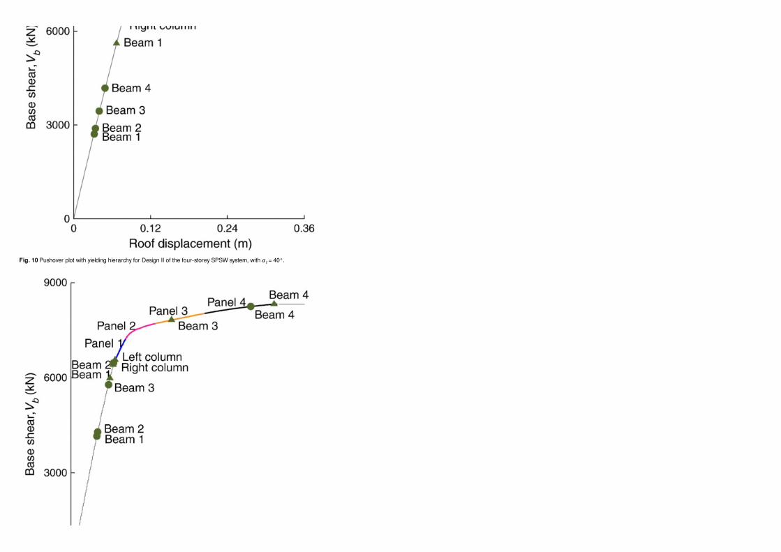
Fig. 10 Pushover plot with yielding hierarchy for Design II of the four-storey SPSW system, with αt = 40°.

Similar results are obtained for Design I of the eight-storey SPSW system. Five trial configurations for this design scenario are achieved by varying αt between 39.75° and to 43.75° at an interval of 1°. Fig. 12 presents the beam tuning results
summary for this design case. The trial design with αt = 41.75° with ‘moderate’ beam sections (W 14 × 213 up to the fourth storey and W 14 × 193 above) results in µd (= 3.99) closest to the target (µt = 4.00).
5.4 Comparison with the ‘AISC method’ design
In order to assess the benefits and limitations of the proposed method versus the standard design practice till date, it is essential to compare the the outcomes for the same scenario. Section 3 provides a typical design of a four-storey SPSW system
Fig. 11 Pushover plot with yielding hierarchy for Design II of the four-storey SPSW system, with αt = 44°.
Fig. 12 Change in µd due to beam tuning, for Design I of the eight-storey SPSW system.

based on the AISC Design Guide 20. An alternative design for the same building (Fig. 1) is obtained for the same design scenario using the proposed PBPD method. The design scenario is defined by the same (ASCE7) design spectrum and µt = 3.50. The
SPSW is designed following the flow-chart in Fig. 5. The NLRHA in beam tuning is performed using the record SYL (Table 1), after scaling it to the same Sa as the design spectrum. This design is referred to as the ‘Proposed method’ design. The design details
are as follows:
• Infill panel thickness (from the first storey upwards) = 3.25, 3.00, 2.40, and 1.45 mm.
• HBE (same section for all floors) = W 14 × 99
• VBE (same section for all storeys) = W 36 × 194
• Τ1, based on an eigenvalue analysis = 1.02 s
• Sa (at Τ1) = 0.833 g.
The performance of the ‘Proposed method’ design is assessed in the same way as of the ‘AISC method’ design, using the same three ground motion records (Table 1). The records are scaled to have Sa = 0.833 g for the NLRHA and the estimation of
Dm. The modelling idealisations in performing the NSPA and NLRHA remain the same as for the ‘AISC method’ design. FromForm the NSPA, the yield displacement (Dy) is obtained as 0.0717 m, with a yield base shear of 3100 kN. The three earthquakes
result in µd values of 3.02, 3.10 and 2.79 (giving an average of 2.97). These values are quite close to the target (µt = 3.50) as opposed to the corresponding ‘AISC method’ design'’s values of 2.36, 2.18 and 1.76, respectively. Fig. 13 shows the displacement
profiles at the instant of maximum roof displacement based on NLRHA using the three scaled records. These profiles are close to the ‘ideal’ profile set as a design target. These displacement profiles also indicate that there is no concentration of plasticity in
any specific floor. From the NSPA performed, it is observed that the ‘AISC method’ design exhibits no proper sequence of yielding, and moreover, there is no formation of plastic hinge at the left end of floor beams (HBE). For the ‘Proposed method’ design, the
yield mechanism is the same as the one assumed in the design method formulation. Also, the yielding is gradual and in proper sequence. These indicate that the performance-based design targets are achieved in the ‘Proposed method’ design, while the
‘AISC method’ design fails to use the ductility capacity of the SPSW system properly.

6 Modified PBPD method for SPSW considering P-Delta effects
P-Delta effects (structure-level secondary moment effects due to geometric nonlinearity) can sometimes be significant for structures, especially for high-rise buildings. Seismic design standards and guidelines (for example,
[10,39,40]) generally specify a simple but reasonably accurate method for incorporating the P-Delta effects in the seismic demand estimation. The general practice is to apply a ‘stability factor/coefficient’ to amplify the seismic demands
based on a linear elastic static analysis of the structure. However, these demands may not realistically represent the ‘actual’ demands obtained using a NLRHA including the P-Delta effects [41]. So far, very little research work is reported in
the published literature regarding P-Delta effects on SPSW systems [33]. The PBPD method proposed in this paper allows the designer to select a target ductility based on the estimated capacity of the SPSW system and do design for that.
The P-Delta effects may be significant in the case of a high-rise building designed to undergo large inelastic deformations (due to the selected µt) subjected to a strong earthquake. Considering this, the proposed PBPD method is modified to
take into account the P-Delta effects wherever necessary.
6.1 Incorporating P-Delta effects in the design formulation
P-Delta effects are incorporated in the proposed PBPD method by modifying the design base shear. The modified design base shear is obtained based on a formulation similar to Eqs. (2)–(8). For the modified formulation, the multistorey SPSW
system is idealised as an inelastic SDOF system having a total seismic mass of M (total seismic weight, W = Mg), and the fundamental modal height of H1. To simplify the formulation, the seismic mass/weight on each floor is assumed to be the same (although
a similar modification can also be proposed for varying floor masses). The P-Delta load at each floor comes from the seismic mass at each floor, and thus the total P-Delta load for the structure, PD = W. Fig. 14 shows sample bilinearised pushover curves for
multi-storey SPSW systems, which also represent the force-deformation behaviour of inelastic SDOF systems the SPSW structures are idealised to. Fig. 14.a corresponds to a SPSW system where P-Delta effects are not accounted for. It also shows the
deformed shapes of the idealised SDOF system at D = Dy and D = Dm. The pushover curve without P-Delta effects has an elastic-perfectly plastic behaviour with yield base shear Vby at the yield roof displacement (Dy). Fig. 14.b corresponds to an SPSW system
where P-Delta effects are included. This part of the figure includes two deformed shapes (at D = Dy and D = Dm) and a bilinearised pushover curve, as well. As P-Delta effects are accounted for in the behaviour, the SDOF system shows a softening behaviour
beyond its yielding (D > Dy1). With an assumption that the inelastic energy demand on the system remains the same, irrespective of including or excluding P-Delta effects, the modified design yield base shear (Vby1) is obtained in a two-step process. In the first
step, the ‘original’ design yield base shear, Vby, is calculated considering no P-Delta effects in the design formulation Eq. (8). In the second step, Vby1 is obtained by equating the areas under the pushover curve for the system without P-Delta effects (Fig. 14.a)
and for the system with P-Delta effects (Fig. 14.b):
Fig. 13 Displacement profiles for the ‘Proposed method’ design SPSW system, at the instant of maximum roof displacement.
(16)

The force-deformation behaviour in Fig. 14.b gives the reduced the base shear Vb1 at D = Dm:
Considering that the initial/elastic stiffness for the two SDOF systems is are the same, and subsequently Vby/Dy = Vby1/Dy1, Eq. (16) can now be written without Dy1 and Vb1:
The solution of this quadratic equation gives the design yield base shear including P-Delta effects (Vby1), in terms of Vby and other ‘known’ parameters:
The fundamental modal height, H1 can be calculated as
where, ϕi1 is the ith floor element in the fundamental mode shape vector, and mi is the lumped mass at the ith floor. After obtaining Vby1, the rest of the modified design procedure (which includes the design of various components of the SPSW system)
remains the same as illustrated in the design flow-chart of Fig. 5.
6.2 Validation of the modified design method
Sample designs scenarios for the eight-storey SPSW system (Designs II, IV and VI, with an aspect ratio hs:L = 1:1 and Designs VIII, X and XII with an aspect ratio hs:L = 1:1.5) are considered here to check the effectiveness of the modified PBPD
method including P-Delta effects. The target displacement ductility ratio is kept the same for these redesigns (µt = 5.0). The P-Delta load on each floor is considered to be equal to the seismic weight on each floor. These redesigns as well as the original
designs (Section 5) are assessed using NSPA and NLRHA, while including the P-Delta effects in these analyses. Tables 8 and 9 provide results summary for these redesigns. These tables also provide a comparison with the original designs in terms of µd, ‘%
Diff.’, ‘Average’ and ‘AbsMax’.
Table 8 Results summary for redesigns and original designs of eight-storey SPSW systems having hs:L = 1:1.
Modified method Original method
Design Record Scale factor µt µd % Diff. µd % Diff.
II SYL 1.30 5 4.23 − 15.4 3.87 − 23.4
IV NH 1.50 5 4.58 − 8.40 4.07 − 18.6
VI KJM 1.90 5 4.31 − 13.8 3.78 − 24.4
Average − 12.5 − 22.1
AbsMax 15.4 24.4
Fig. 14 Force-deformation curves of idealised SDOF systems for SPSW (a) without accounting for P-Delta effects, and (b) with P-Delta effects.
(17)
(18)
(19)
(20)

AbsMax 15.4 24.4
Table 9 Results summary for redesigns and original designs of eight-storey SPSW systems having hs:L = 1:1.5.
Modified method Original method
Design Record Scale factor µt µd % Diff. µd % Diff.
VIII SYL 1.30 5 4.80 − 4.00 4.10 − 18.0
X NH 1.50 5 4.35 − 13.0 3.93 − 21.4
XII KJM 1.90 5 4.37 − 12.6 3.82 − 23.6
Average − 9.87 − 21.0
AbsMax 13.0 23.6
For redesigns with hs:L = 1:1 (Table 8), the average % Diff. is −– 12.5, as opposed to −– 22.1 for the original designs. The corresponding AbsMax values are 15.4 and 24.4 for redesigns and original designs, respectively. Table 8 shows that for each
design scenario considered here, the modified design methodology is more efficient in achieving µd closer to µt. Results for hs:L = 1:1.5 (Table 9) puts the modified design method in an even better position. Here, the average % Diff. (= −– 21.0) of the original
designs is reduced to −– 9.87 for the redesigns. Similarly, the AbsMax (= 23.6) of the original designs is also reduced to 13.0 for the redesigns.
7 Summary and conclusions
A performance-based plastic design procedure, considering a selected displacement ductility ratio and a yield mechanism as the performance targets, is proposed in this paper for steel plate shear wall systems with rigid beam-to-
column connections. 30 design cases of four-storey (low-rise) and 12 design cases of eight-storey (medium-rise) SPSW configurations, varying in target displacement ductility ratio, design ground motion, and steel panel aspect ratio, are
achieved using the proposed PBPD method. Performance assessment of these designs clearly shows that, for a large variety of design scenarios, the proposed design method is very effective in achieving the performance targets.
The proposed design method is also compared with the existing AISC design guide for steel plate shear walls, through the sample design case study of a four-storey system. Both design methods are used to obtain designs for the
same design scenario. While the proposed design is able to reach very close to its stated performance targets, the AISC method design fails to properly utilise the ductility capacity offered by the SPSW system.
The proposed PBPD method is modified to account for P-Delta effects wherever necessary. A design equation is proposed to modify the design yield base shear in case P-Delta effects are expected. Six design case studies for the
eight-storey SPSW system, with a target displacement ductility ratio of 5.0, show that the modified PBPD method is more effective in achieving the performance targets compared to the PBPD method proposed originally in this work. The
modified method still remains to be tested for high-rise SPSW systems, where P-Delta methods are even more. However, on a relative scale, the modified method is expected to be still more effective for such cases, compared to the original
PBPD proposed here.
While both PBPD methods (original and modified for P-Delta) provide step-by-step procedures to obtain designs that are very effective in achieving displacement-based performance targets, these methods lack in offering a very
precise beam (HBE) design method. Experience of the designs presented here suggests that beams tuned to αt around 38°–42° typically provide an ‘optimum’ design. However, future studies in this area should come up with more precise
design guidelines/equations for beams in an SPSW system. Number of iterations involved in the design process is another issue that needs to be dealt with in the following studies in this area. Similar to any other design method, the number
of iterations can of course be reduced as we build our experience in the proposed PBPD methods. Besides these, material strain-hardening is another aspect that remains to be incorporated in the proposed design methods. As mentioned
earlier, the proposed PBPD methods also need to be put into a probabilistic design framework, which is a work in progress by our research team, and performance levels should be defined in terms of interstorey drift ratio or displacement
ductility ratio for SPSW.
Acknowledgement
The authors of this paper gratefully acknowledge the guidance received over the past years from Prof. Subhash C. Goel. The work presented here is funded by a sponsored research grant from the Department of Science and
Technology (DST), Govt. of India. However, results and opinions presented in this paper are solely of the authors, and not necessarily representing the views of DST. The authors would also like to thank the reviewers for their suggestions
which enhanced this paper.
References

References
[1]
S. Ghosh and S.B. Kharmale, Research on steel plate shear wall: past, present and future, In: L.M. Becker, (Ed), Structural steel and castings: shapes and standards, properties and applications, 2010, Nova Science Publishers Inc.;
Hauppauge, USA.
[2]
L.J. Thorburn, G.L. Kulak and C.J. Montgomery, Analysis of steel plate shear walls, Structural engineering report no. 107, 1983, Department of Civil Engineering, University of Alberta; Edmonton, Canada.
[3]
P.A. Timler and G.L. Kulak, Experimental study of steel plate shear walls, Structural engineering report no. 114, 1983, Department of Civil Engineering, University of Alberta; Edmonton, Canada.
[4]
E.W. Tromposch and G.L. Kulak, Cyclic and static behaviour of thin panel steel plate shear walls, Structural engineering report no. 145, 1987, Department of Civil Engineering, University of Alberta; Edmonton, Canada.
[5]
R.G. Driver, G.L. Kulak, D.L.J. Kennedy and A.E. Elwi, Seismic behaviour of steel plate shear walls, Structural engineering report no. 215, 1997, Department of Civil Engineering, University of Alberta; Edmonton, Canada.
[6]
M. Elgaaly, Thin steel plate shear walls behavior and analysis, Thin-Walled Struct 32 (1–3), 1998, 151–180.
[7]
CSA, Limit states design of steel structures, 1994, Canadian Standards Association; Willowdale, Canada.
[8]
CSA, Limit states design of steel structures, 2001, Canadian Standards Association; Willowdale, Canada.
[9]
J.W. Berman and M. Bruneau, Plastic analysis and design of steel plate shear walls, J Struct Eng 129 (11), 2003, 1448–1456.
[10]
AISC, Seismic provisions for structural steel buildings, 2005, American Institute of Steel Construction Inc.; Chicago, USA.
[11]
AISC, Seismic provisions for structural steel buildings, 2010, American Institute of Steel Construction Inc.; Chicago, IL, USA.
[12]
CSA, Limit states design of steel structures, 2009, Canadian Standards Association; Willowdale, Canada.
[13]
R. Sabelli and M. Bruneau, Design guide 20: steel plate shear walls, 2007, American Institute of Steel Construction Inc.; Chicago, USA.
[14]
ASCE, SEI/ASCE7, minimum design loads for buildings and other structures (including supplement no. 1), 2005, American Society of Civil Engineers; Reston, USA.
[15]
AISC, Specifications for structural steel buildings, 2005, American Institute of Steel Construction Inc.; Chicago, USA.
[16]

[16]
R. Purba and M. Bruneau, Case study on the impact of horizontal boundary elements design on seismic behavior of steel plate shear walls, J Struct Eng 138 (5), 2012, 645–657.
[17]
J.W. Berman and M. Bruneau, Capacity design of vertical boundary elements in steel plate shear walls, Eng J 45 (1), 2008, 57–71.
[18]
D. Vian, Steel plate shear walls for seismic design and retrofit of building structures, [PhD Dissertation]2005, UniversityUnivesity of Buffalo; Buffalo, USA.
[19]
D. Vian, M. Bruneau, K.C. Tsai and Y.C. Lin, Special perforated steel plate shear walls with reduced beam section anchor beams I: experimental investigation, J Struct Eng 135 (3), 2009, 211–220.
[20]
D. Vian, M. Bruneau and R. Purba, Special perforated steel plate shear walls with reduced beam section anchor beams II: analysis and design recommendations, J Struct Eng 135 (3), 2009, 221–228.
[21]
B. Qu and M. Bruneau, Capacity design of intermediate horizontal boundary elements of steel plate shear walls, J Struct Eng 136 (6), 2010, 665–675.
[22]
S.S. Lee and S.C. Goel, Performance-based design of steel moment frames using target drift and yield mechanism, Research report UMCEE 01-07, 2001, University of Michigan; Ann Arbor, USA.
[23]
S.H. Chao and S.C. Goel, Performance-based design of EBF using target drift and yield mechanism, Research report UMCEE 05-05, 2005, University of Michigan; Ann Arbor, USA.
[24]
S.C. Goel and S.H. Chao, Performance-based plastic design: earthquake-resistant steel structures, 2009, International Code Council; Washington, USA.
[25]
S. Ghosh, A. Das and F. Adam, Design of steel plate shear walls considering inelastic drift demand, J Constr Steel Res 65 (7), 2009, 1431–1437.
[26]
M.K. Gupta, S.B. Kharmale and S. Ghosh, Ductility-based seismic design of steel plate shear walls: practical application using standard sections, Int J Adv Struct Eng 1 (2), 2009, 93–110.
[27]
BIS, SP: 6(1)-1964: handbook for structural engineers, no. 1, structural steel sections, 1964, Bureau of Indian Standards; New Delhi, India.
[28]
S.B. Kharmale and S. Ghosh, Seismic lateral force distribution for ductility-based design of steel plate shear walls, J Earthq Tsunami 6 (1), 2012, 1–24, [1250004].
[29]
C.O. Kurban and C.A. Topkaya, A numerical study on response modificationmodication, overstrength, and displacement amplificationamplication factors for steel plate shear wall systems, Earthq Eng Struct Dyn 38, 2009, 497–516.
[30]
ICC, International Building Code (IBC), 2006, International Code Council; Whittier, USA.
[31]
H. Akiyama, Earthquake-resistant limit-state design of buildings, 1985, University of Tokyo Press; Tokyo, Japan.

[32]
N.M. Newmark and W.J. Hall, Earthquake spectra and design, 1982, EarthquakeEarhquake Engineering Research Institute; El Cerrito, USA.
[33]
A.K. Bhowmick, R.G. Driver and G.Y. Grondin, Seismic analysis of steel plate shear walls considering strain rate and P-delta effects, J Constr Steel Res 65 (5), 2009, 1149–1159.
[34]
A.K. Chopra and R.K. Goel, Direct displacement-based design: use of inelastic vs. elastic design spectra, Earthq Spectra 17 (1), 2001, 47–64.
[35]
C.A. Topkaya and C.O. Kurban, Natural periods of steel plate shear wall systems, J Constr Steel Res 65 (3), 2009, 542–551.
[36]
V. Prakash, G.H. Powell and S. Campbell, DRAIN-2DX, base program description and user guide: version 1.10, Report no. UCB/SEMM-93/17, 1993, University of California; Berkeley, USA.
[37]
N.M. Baldvins, J.W. Berman, L.N. Lowes, T.M. Janes and N.A. Low, Fragility functions for steel plate shear walls, Earthq Spectra 28 (2), 2012, 405–426.
[38]
J.J. Shishkin, R.G. Driver and G.Y. Grondin, Analysis of steel plate shear walls using the modified strip model, Structural engineering report no. 215, 2005, Department of Civil Engineering, University of Alberta; Edmonton, Canada.
[39]
BSSC, NEHRP recommended provisions for seismic regulations for new buildings and other structures, FEMA 368 and 369, 2000, Federal Emergency Management Agency; Washington, USA.
[40]
NRCC, NBCC, National Building Code of Canada, 2005, National Research Council of Canada (NRCC); Ottawa, Canada.
[41]
A. Gupta and H. Krawinkler, Seismic demands for performance evaluation of steel moment resisting frame structures, John A. Blume Earthquake Engineering Center report no. 132, 1999, Department of Civil Engineering, Stanford University;
Stanford, USA.
Highlights
• A novel PBPD method for SPSW with rigid beam-to-column connections
• Pre-selected ductility demand and yield mechanism as performance targets
• Testing effectiveness of the proposed PBPD using a large variety of case studies
• Comparison with the existing design procedures/guidelines
• ModificationModfication in proposed PBPD method to incorporate P-Delta effects
• Validation of modified PBPD through case studies
Queries and Answers

Query:
Please confirm that given names and surnames have been identified correctly.
Answer: Yes
Query:
Please check the capturing of table entries found in the fourth column under the heading “Component” if appropriate, and correct if necessary.
Answer: Appropriate, don't change
Query:
Please check the telephone/fax number of the corresponding author, and correct if necessary.
Answer: Checked okay.
Query:
The first section heading “Existing design provisions for steel plate shear walls” has been changed to “Introduction”, as per journal instruction. Please check, and correct if necessary.
Answer: Please change back to the original (Exisiting ...). UNDO the changes made.