Embed Size (px)
Citation preview
Introduction
Similar to terrestrial applications, dual-frequency GPSreceivers offer numerous advantages over single-fre-quency receivers in space applications. Even though thebasic navigation requirements of many spacecraft canwell be met by single-frequency receivers, the secondfrequency is of great interest for scientific missions and akey to ultimate accuracy in absolute and relative navi-gation (Yunck 2004). It allows the direct elimination ofionospheric path delays and thus gives full access to the
accuracy of carrier-phase based measurements. GPStracking of low Earth satellites has dramatically im-proved our knowledge of the Earth’s gravity field (Re-igber et al. 2004) and GPS based radio occultationmeasurements are an indispensable source of informa-tion for ionospheric and tropospheric research (Kur-sinski et al. 1997). In carrier-phase differential GPS(CDGPS), dual-frequency measurements enable a reli-able resolution of integer ambiguities even at largebaselines and non-negligible differential ionospheric de-lays (Kroes et al. 2005).
Oliver Montenbruck
Miquel Garcia-Fernandez
Jacob Williams
Performance comparison of semicodelessGPS receivers for LEO satellites
Received: 4 November 2005Published online: 22 March 2006� Springer-Verlag 2006
Abstract This report provides a de-tailed performance analysis of threesemicodeless dual-frequency GPSreceivers for use in low Earth orbit(LEO). The test set comprises theIGOR receiver, which represents afollow-on of the flight-provenBlackJack receiver, as well as twogeodetic receivers (NovAtel OEM4-G2 and Septentrio PolaRx2), whichare entirely based on commercial-off-the-shelf technology (COTS). Allthree receivers are considered forupcoming flight projects or experi-ments and have undergone at least apreliminary environmental qualifi-cation program. Using extensivesignal simulator tests, the cold startsignal acquisition, tracking sensitiv-ity, differential code biases, rawmeasurement accuracy, and naviga-tion accuracy of each receiver havebeen assessed. All tests are based ona common scenario that is repre-sentative of an actual space mission
and provides a realistic simulation ofthe signal dynamics and quality on ascientific LEO satellite. Compared tothe other receivers, the IGORinstrument exhibits a superiortracking sensitivity and is thus bestsuited for occultation measurementswith low tangent point altitudes. TheOEM4-G2 and PolaRx2 receiversare likewise shown to properly trackdual-frequency GPS signals andnormal signal levels and to provideaccurate code and carrier phasemeasurements. Given their limitedresource requirements, these receiv-ers appear well suited for preciseorbit determination applications andionospheric sounding onboard ofmicrosatellites with tight missionbudgets.
Keywords Spaceborne GPS ÆSemicodeless tracking ÆIGOR Æ OEM4-G2 Æ PolaRx2 ÆBlackJack
GPS Solut (2006) 10: 249–261DOI 10.1007/s10291-006-0025-9 ORIGINAL ARTICLE
O. Montenbruck (&)Miquel Garcia-FernandezGerman Space Operations Center,Deutsches Zentrum fur Luft- undRaumfahrt, 82230 Weßling,GermanyE-mail: [email protected].: +49-8153-281195Fax: +49-8153-281450
J. WilliamsCenter for Space Research,University of Texas at Austin,Austin, TX 78759, USA
Over the past decade, scientific applications ofspaceborne GPS have almost exclusively relied on theBlackJack (or TurboRogue Space Receiver, TRSR-2)receiver. This receiver has been developed by NASA’sJet Propulsion Laboratory (JPL) and successfully flownon numerous satellites including Oersted, Champ, SAC-C, ICEsat, GRACE, and Jason-1. More recently, JPLhas licensed core technology to Broadreach Engineering,which now manufactures the IGOR receiver as aBlackJack follow-on version with improved spacehardness. Within Europe, ESA has continuously sup-ported and promoted the independent development ofdual-frequency receivers for space applications throughthe AGGA (Advanced GPS/GLONASS ASIC) corre-lator. These efforts have resulted in the GRAS instru-ment of SAAB Aerospace to be flown onboard theMETOP satellite as well as Laben’s Lagrange receiver,which, for example, has been selected for ESA’s GOCEmission.
All of the aforementioned receivers are characterizedby a high level of specialization, a limited productionvolume, and a demanding qualification program. Thisresults in a representative price tag of $1 million andbursts the budget of typical small satellite science mis-sions. In view of this situation, scientists and industryhave repeatedly expressed their interest in affordablealternatives for missions where utmost reliability andrigorous space qualification may not be mandatory.Based on promising experience with single-frequencyreceivers, DLR has therefore taken the initiative toinvestigate the use of existing commercial-off-the-shelf(COTS) dual-frequency receivers for space applicationsand to perform a basic qualification program as well asinitial flight demonstrations. As part of this effort, Nov-Atel’s OEM4-G2L and Septentrio’s PolaRx2 receiverhave been demonstrated to cope with the signal dynamicsand the environmental conditions of a low Earth satellite(Langley et al. 2004; Leyssens and Markgraf 2005).Further motivation for the adaptation of COTS receiversstems from the fact that the BlackJack receiver has itselfevolved from prior generations of digital receivers forhigh-precision ground use (Rogue, TurboRogue).
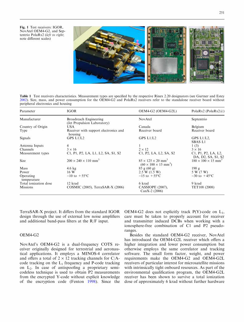
The present study provides a detailed performanceassessment and comparison of the space qualified IGORreceiver with the COTS-based OEM4-G2 and PolarRx2receivers (cf. Fig. 1) based on a harmonized set of signalsimulator tests. Key parameters of the three employedreceivers are summarized in Table 1. Following a gen-eral characterization of each receiver, the simulator testscenario and the fundamental analysis steps are de-scribed in the subsequent sections of this report. Asidefrom the basic questions of tracking and navigationaccuracy, the study addresses the cold start time, thetracking sensitivity, semicodeless tracking losses, anddifferential code biases (DCBs) to enable a propercharacterization of the receiver performance.
For completeness, we mention that at least three othersemicodeless dual-frequency GPS receivers for spaceapplications are currently offered by European andJapanese manufacturers but could not be accessed for thepresent study. These include the Lagrange receiver ofLaben (Marradi et al. 2001), the GRAS instrument ofSAAB Aerospace (Silvestrin et al. 2000), and the dualfrequency space receiver (DFSG) of NEC/Toshiba (Buist2002). So far, however, no relevant laboratory test dataor in-flight performance data have been publicly releasedfor any of these receivers. The test strategy described inthis report may nevertheless provide a guideline for fu-ture analysis and serve as a basis for an extended com-parison of spaceborne GPS receivers.
Receivers
IGOR
The IGOR Integrated GPS and Occultation Receiver(BRE 2003) is a follow-on of JPL’s BlackJack GPS re-ceiver for space applications. IGOR closely matches theCHAMP BlackJack design but employs a higher degreeof space qualified electronics components than JPL’soriginal version. First flights of the IGOR receiver areforeseen in 2005/2006 onboard the Taiwanese Formo-sat-3 (formerly COSMIC) constellation (Wu et al. 2005)and the German TerraSAR-X mission.
The receiver supports a total of four antenna inputs,which can be flexibly assigned for navigation andoccultation measurements. The 48 individual receiverchannels can be allocated in sets of three to track C/A-,P1-, and P2-code for up to 16 GPS satellites. Duringantispoofing, a patented, codeless tracking technique isused to estimate P-code from the encrypted Y-code(Thomas 1995; Meehan et al. 2000). Aside from themain tracking mode, the receiver can operate in occul-tation mode to collect measurements when GPS satel-lites rise or set. Even though the original design of theBlackJack receiver involves a large number of COTScomponents, extensive ground tests and the availableflight experience provide adequate evidence for its sur-vivability in a space environment. The IGOR receiver isspecified to tolerate a total ionization dose of at least 12krad (Table 1), which is adequate for mission durationsof several years in a low Earth orbit (LEO). A high levelof fault tolerance is provided through four independentR/F input strings and two independent digital sections.
Due to its use in multiple space missions the Black-Jack receiver is well characterized by laboratory testsand in-flight validations (Williams et al. 2002; Monten-bruck and Kroes 2003) and similar results may beexpected for the IGOR design. For the present tests, theTerraSAR-X flight unit has been made available bythe GeoForschungsZentrum (GFZ), Potsdam and the
250
TerraSAR-X project. It differs from the standard IGORdesign through the use of external low noise amplifiersand additional band-pass filters at the R/F input.
OEM4-G2
NovAtel’s OEM4-G2 is a dual-frequency COTS re-ceiver originally designed for terrestrial and aeronau-tical applications. It employs a MINOS-4 correlatorand offers a total of 2 · 12 tracking channels for C/A-code tracking on the L1 frequency and P-code trackingon L2. In case of antispoofing a proprietary semi-codeless technique is used to obtain P2 measurementsfrom the encrypted Y-code without explicit knowledgeof the encryption code (Fenton 1998). Since the
OEM4-G2 does not explicitly track P(Y)-code on L1,care must be taken to properly account for receiverand transmitter induced DCBs when working with aionosphere-free combination of C1 and P2 pseudo-ranges.
Besides the standard OEM4-G2 receiver, NovAtelhas introduced the OEM4-G2L receiver which offers ahigher integration and lower power consumption butotherwise employs the same correlator and trackingsoftware. The small form factor, weight, and powerrequirements make the OEM4-G2 and OEM4-G2Lreceivers of particular interest for microsatellite missionswith intrinsically tight onboard resources. As part of theenvironmental qualification program, the OEM4-G2Lreceiver has been shown to survive a total ionizationdose of approximately 6 krad without further hardware
Fig. 1 Test receivers: IGOR,NovAtel OEM4-G2, and Sep-tentrio PolaRx2 (left to right;note different scales)
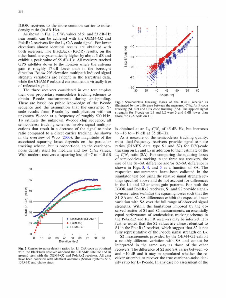
Table 1 Test receivers characteristics. Measurement types are specified by the respective Rinex 2.20 designators (see Gurtner and Estey2002). Size, mass, and power consumption for the OEM4-G2 and PolaRx2 receivers refer to the standalone receiver board withoutperipheral electronics and housing
Parameter IGOR OEM4-G2 (OEM4-G2L) PolaRx2 (PolaRx2@)
Manufacturer Broadreach Engineering(Jet Propulsion Laboratory)
NovAtel Septentrio
Country of Origin USA Canada BelgiumType Receiver with support electronics and
housingReceiver board Receiver board
Signals GPS L1/L2 GPS L1/L2 GPS L1/L2,SBAS L1
Antenna Inputs 4 1 1 (3)Channels 3 · 16 2 · 12 3 · 16Measurement types C1, P1, P2, LA, L1, L2, SA, S1, S2 C1, P2, LA, L2, SA, S2 C1, P1, P2, LA, L2,
DA, D2, SA, S1, S2Size 200 · 240 · 110 mm3 85 · 125 · 20 mm3
(60 · 100 · 15 mm3)180 · 100 · 15 mm3
Mass 4.6 kg 85 g (60 g) 190 gPower 16 W 2.5 W (1.5 W) 5 W (7 W)Operatingtemperature
)10 to +55�C )15 to +55�C )30 to +45�C
Total ionization dose 12 krad 6 krad 9 kradMissions COSMIC (2005), TerraSAR-X (2006) CASSIOPE (2007),
CanX-2 (2006)TET108 (2008)
251
modifications (Markgraf and Montenbruck 2004).While this is considered adequate for LEO missiondurations of up to 2 years, further investigations of thesingle-event upset and latch-up sensitivity of the receiverare presently pending.
In view of promising test results and the modesthardware cost, the OEM4-G2L receiver has been se-lected for the e-POP payload of the Canadian CAScadeDemonstrator Smallsat and Ionospheric Polar Explorer(CASSIOPE) mission (Langley et al. 2004). Launch ofthe spacecraft is presently scheduled for 2007 and willprovide complementary flight experience for the use ofCOTS based dual frequency GPS technology in space.Even 1 year earlier, an experimental flight of an OEM4-G2L receiver is planned onboard the CanX-2 picosat-ellite of the University of Calgary (Rankin 2004).
PolaRx2
As a spin-off from ESA’s AGGA correlator develop-ment, the Belgian company Septentrio has developed theGNSS Receiver Core (GreCo) and a matching front-endchip (GreFe) for use in geodetic dual-frequency GPSreceivers. Their recent PolaRx2 receiver offers a total of48 channels for GPS and SBAS tracking and is availablein versions with one or three antenna inputs. Threeindividual channels are normally combined to performC/A-code and P(Y)-code tracking on the L1 and L2
frequency of a single GPS satellite. The semicodelesstracking concept employed with the family of AGGAand GreCo correlators (Silvestrin and Cooper 2000)resembles the well-known Z-tracking scheme (see, e.g.Woo 2000) for encrypted P-code but is expected toprovide a better estimation of the W-code bit and thus areduction of the implied squaring losses. The use of tightcorrelator spacings and narrow tracking loop band-widths furthermore contributes to high-quality code andcarrier.
As part of a qualification program for in-orbitapplications conducted by DLR and Septentrio (Leys-sens and Markgraf 2005), the PolaRx2 receiver hasundergone a first series of signal simulator and envi-ronmental tests (total ionization dose, thermal/vacuum,and vibration). In this context, the PolaRx2 firmwarehas received minor modifications and patches to prop-erly support the signal dynamics encountered onboard aLEO satellite. The Doppler search window has beenextended to 45 kHz to ensure a robust cold startacquisition, but no changes of the tracking loopparameters were performed. For use in space environ-ment, the PolaRx2 receiver has demonstrated an ade-quate range of operations temperatures and total doseresistance (9 krad) but presently lacks a characterizationof single-event upset and latch-up sensitivity as well asdedicated protective measures. Within DLR’s On-Orbit
Verification program a demonstration flight of the Po-laRx2 receiver is presently foreseen onboard the TET108satellite in 2008.
Performance testing and analysis
Test configuration
The tests employed for the present performance studyhave been conducted on Spirent STR4760 and STR7790GPS signal simulators (Spirent 2004), which allow for arealistic modeling of a spaceborne user trajectory. Asun-synchronous, polar orbit with an altitude of 515 kmand an inclination of 97.44� has been adopted, whichclosely resembles the TerraSAR-X mission profiles. Themodeling of ionospheric path delays has been based onthe assumption of a constant vertical total electroncontent of 10 TECU and a Lear mapping function (Lear1987). In accord with the study scope, no broadcastephemeris errors, clock dithering, or multipath errorshave been applied in the simulations. Based on thespecified GPS constellation data and the simulated usersatellite trajectory, truth values of the pseudoranges foreach observed GPS satellite have been computed offlinefor comparison with the actual receiver measurements.
For a realistic simulation of observed signalstrengths, we adopted the gain pattern of a SensorSystems S67-1575-14 GPS antenna with choke ring,which is currently employed on various satellites such asCHAMP and GRACE. A digitized antenna diagram foruse with Spirent signal simulators has been generatedwithin the ICEsat project (Williams et al. 2002) andmade available for the present analysis. Based on ref-erence data from outdoor tests, the power of the L1 C/Acode signal generated by the simulator was adjusted suchas to achieve a closely matching range of C/N0 readingsin the simulations.
As noted by Van Dierendonck (1995), a higher thannormal signal level is usually required to compensate forthe higher noise temperature experienced in simulatortesting compared to the usual antenna sky temperature.While an increase of about +8 to +10 dB has earlierbeen recommended for single-frequency receivers withnarrow front-end band widths in Montenbruck andHolt (2002), notably higher signal levels were requiredfor the employed dual-frequency receivers. Even thoughall test receivers were operated with external low noiseamplifiers designed for use with a passive antenna, thesignal level at the R/F outlet of the simulator had to beraised by +13 to +17 dB relative to a nominal L1 C/Acode signal power of )130 dBm. In accord with the GPSsignal specification the P-code signal power was fur-thermore configured to be 3 dB less than that of the C/Acode signal on the L1 frequency and 6 dB less on the L2
frequency.
252
Finally, the antispoofing bit (i.e. bit 19 of the hand-over word) was activated in the navigation messages toensure that none of the test receivers would attempt adirect P-code acquisition. Even though the Spirentsimulators also provide for the generation of a pseudo-Y-code (or Z-code), use of this feature did not affect thetracking accuracy in our tests.
Cold start acquisition
As a prerequisite for operation in a LEO, a spaceborneGPS receiver must be able to properly acquire GPSsignals and to compute an initial navigation solutionirrespective of the involved signal dynamics. Due to thehigh orbital velocity of a LEO satellite, a maximumrange rate of ±8.5 km/s can be encountered near risingor setting of a GPS satellite. Along with uncertainties ofthe local reference frequency, the receiver must thusaccommodate a typical Doppler search space of±45 kHz for a guaranteed cold start acquisition. Whilevarious single-frequency GPS receivers for space appli-cations support a warm start acquisition based on apriori time and orbit information, no such features areavailable in any of the receivers considered here. On theother hand, the IGOR, OEM4-G2, and PolaRx2receivers benefit from a large number of individualcorrelator channels which enable a parallel search ofcode/frequency bins and a corresponding reduction ofthe acquisition time.
To assess the cold start performance, a series of re-ceiver reboots has been conducted at random epochsthroughout the simulated test scenario. All receiverswere able to safely acquire satellites and to achievenavigation fix in due time, but notable performancedifferences were obvious (cf. Table 2). Surprisingly, theIGOR receiver exhibited the longest time-to-first-fix(TTFF) despite its dedicated design for space use and anadequately large number of tracking channels. Afterpower-up, the receiver remains in a start-up state (beepmode) for about 2 min before the actual signal search isinitiated. Thereafter it took between 3 and 14 min toachieve a first navigation fix. The average TTFFamounted to roughly 10 min (including beep mode).
Among the three receivers considered here, theOEM4-G2 appears least prepared for GPS signalacquisition in LEO due to the moderate number ofcorrelator channels and the restricted Doppler search
window of ±4.5 kHz. However, most of the time, thereexists a subset of visible GPS satellites for which theDoppler shift is within the reduced search range of ter-restrial receivers. This results in adequate acquisitiontimes even for unmodified receivers such as the OEM4-G2. After power-up, the receiver took about 7 s to startoperation and mostly locked to the C/A code of a firstGPS satellite just a few seconds later. Following a suc-cessful frame lock and decoding of the frame header, acoarse time was generally available within about 40 safter boot. A navigation fix (requiring four trackedsatellites and successful decoding of the respective nav-igation messages) was achieved within 2–10 min. Oncethe position and velocity were known to the receiver, theremaining satellites were acquired within less than aminute, if a valid almanac was available in the nonvol-atile memory (NVM). Otherwise, the acquisition of thefull GPS constellation could take at most 12.5 moreminutes.
The best overall results were achieved by the PolaRx2receiver which obtained a full navigation fix within 1–3 min after a reboot in cold start conditions. This per-formance may in part be attributed to the large numberof correlator channels and an adequate Doppler searchspace, even though the same is obviously true for theIGOR receiver as well. From an operational point ofview, the short acquisition time is of great benefit andmay serve as a reference for the design of future spacereceivers. It helps to minimize the outage times afteroccasional receiver set-ups and allows a power-saving,intermittent receiver utilization.
Signal-to-noise ratio and squaring losses
For a given tracking loop design, the achieved code andcarrier noise in a GPS receiver is primarily a function ofthe signal quality as measured by the ratio C/N0 ofcarrier to noise power in a 1 Hz bandwidth. As a ref-erence for the proper interpretation of data providedlater in this report we first determined the variation ofC/N0 with elevation in a series of outdoor tests (Ardaens2005). The employed antenna system comprises a pas-sive Sensor Systems S67-1575-14 antenna with chokering and a Spectrum Microwave preamplifier with anoise figure of better than 2 dB. For the IGOR receiver,no such tests could be conducted, but flight data of theCHAMP BlackJack receiver were available as a sub-stitute. Following Montenbruck and Kroes (2003) therelation
CN0¼ 20 log 10
SNRffiffiffi
2p
� �
: ð1Þ
was employed to convert the signal-to-noise amplituderatios (SNR in units of V/V) given by the BlackJack and
Table 2 Cold start acquisition times
Receiver TTFF Notes
IGOR 3–16 min Including 2 min ‘‘beep mode’’OEM4-G2 2–10 minPolaRx2 1–3 min Including initial self-test
253
IGOR receivers to the more common carrier-to-noise-density ratio (in dB–Hz).
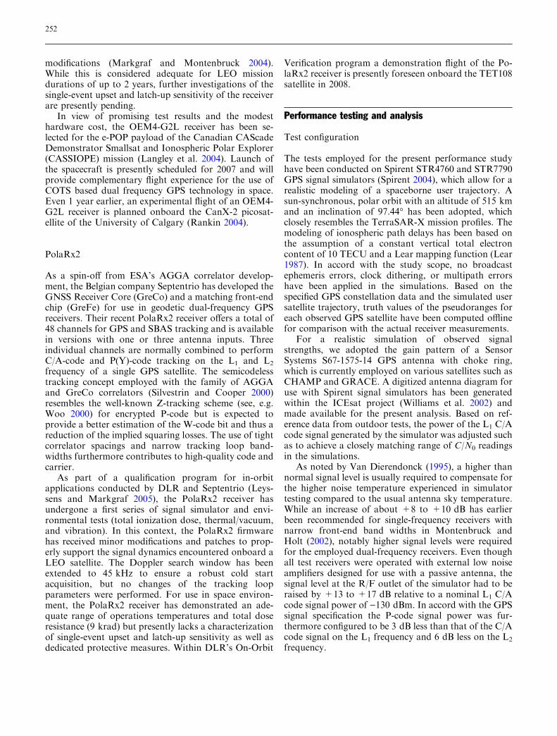
As shown in Fig. 2, C/N0 values of 51 and 53 dB–Hznear zenith can be achieved with the OEM4-G2 andPolaRx2 receivers for the L1 C/A code signal. For lowerelevations almost identical results are obtained withboth receivers. The BlackJack (IGOR) results, on theother hand, are systematically higher by about 3 dB andexhibit a peak value of 55 dB–Hz. All receivers trackedGPS satellites down to the horizon where the antennagain is roughly 17 dB lower than in the boresightdirection. Below 20� elevation multipath induced signalstrength variations are evident in the terrestrial data,while the CHAMP onboard environment is virtually freeof reflected signal.
The three receivers considered in our test employtheir own proprietary semicodeless tracking schemes toobtain P-code measurements during antispoofing.These are based on public knowledge of the P-codesequence and the assumption that the encrypted Y-code results from P-code by multiplication with anunknown W-code at a frequency of roughly 500 kHz.To estimate the unknown W-code chip sequence, allsemicodeless tracking schemes involve signal multipli-cations that result in a decrease of the signal-to-noiseratio compared to a direct carrier tracking. As shownin the overview of Woo (2000), the magnitude of theassociated squaring losses depends on the particulartracking scheme, but is proportional to the carrier-to-noise density itself for medium and low C/N0 values.With modern receivers a squaring loss of )7 to )10 dB
is obtained at an L2 C/N0 of 45 dB–Hz, but increasesto )16 to )19 dB at 35 dB–Hz.
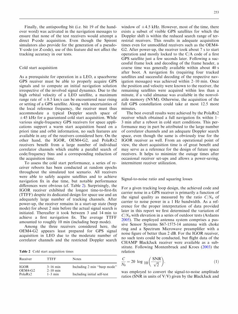
As a measure of the semicodeless tracking quality,most dual-frequency receivers provide signal-to-noiseratios (RINEX data type S1 and S2) for P(Y)-codetracking on L1 and L2 in addition to their estimate of theL1 C/N0 ratio (SA). For comparing the squaring lossesof semicodeless tracking in the three test receivers, thesize of the S1–SA difference and/or S2–SA difference isshown in Figs. 3, 4, and 5 as a function of SA. Therespective measurements have been collected in thesimulator test bed using the relative signal strength set-tings specified above and do not account for differencesin the L1 and L2 antenna gain patterns. For both theIGOR and PolaRx2 receivers, S1 and S2 provide signal-to-noise ratios including the squaring losses such that theS1–SA and S2–SA differences exhibit the expected linearvariation with SA over the full range of observed signalstrengths. Within the limitations imposed by the ob-served scatter of S1 and S2 measurements, an essentiallyequal performance of semicodeless tracking schemes inthe PolaRx2 and IGOR receivers may be inferred. It isfurther noted that the S2 values are almost identical toS1 in the PolaRx2 receiver, which suggest that S2 is notfully representative of the P-code signal strength on L2.
S2 measurements provided by the OEM4-G2 exhibita notably different variation with SA and cannot beinterpreted in the same way as those of the otherreceivers. The difference of S2 and SA varies between )5and )10 dB and it may be speculated whether the re-ceiver attempts to recover the true carrier-to-noise den-sity ratio for L2 P-code. In any case no assessment of the
30
35
40
45
50
55
60
0 10 20 30 40 50 60 70 80 90Elevation [deg]
C/N
0(L
1C
/A)
[dB
Hz]
BlackJack (CHAMP)PolaRx2)OEM4-G2
Fig. 2 Carrier-to-noise-density ratios for L1 C/A code as obtainedwith the BlackJack receiver onboard the CHAMP satellite and inground tests with the OEM4-G2 and PolaRx2 receivers. All datahave been collected with identical antennas (Sensor Systems S67-1575-14) and choke rings
-30
-25
-20
-15
-10
-5
0
30 35 40 45 50 55 60
S1/
2-S
A [d
b-H
z]
SA [db-Hz]
S1S2
Fig. 3 Semicodeless tracking losses of the IGOR receiver asillustrated by the difference between the measured C/N0 for P-codetracking (S1, S2) and C/A code tracking (SA). The applied signalstrengths for P-code on L1 and L2 were 3 and 6 dB lower thanthose for C/A code on L1
254
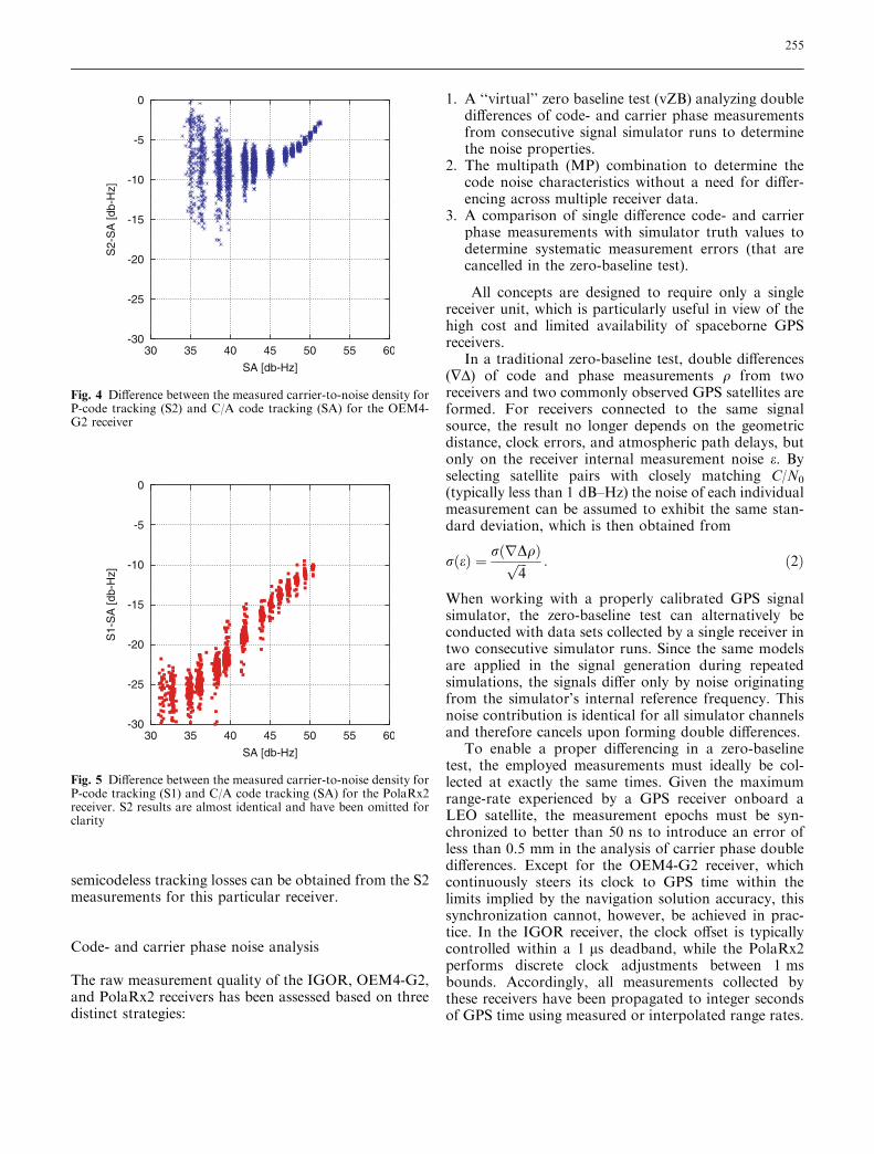
semicodeless tracking losses can be obtained from the S2measurements for this particular receiver.
Code- and carrier phase noise analysis
The raw measurement quality of the IGOR, OEM4-G2,and PolaRx2 receivers has been assessed based on threedistinct strategies:
1. A ‘‘virtual’’ zero baseline test (vZB) analyzing doubledifferences of code- and carrier phase measurementsfrom consecutive signal simulator runs to determinethe noise properties.
2. The multipath (MP) combination to determine thecode noise characteristics without a need for differ-encing across multiple receiver data.
3. A comparison of single difference code- and carrierphase measurements with simulator truth values todetermine systematic measurement errors (that arecancelled in the zero-baseline test).
All concepts are designed to require only a singlereceiver unit, which is particularly useful in view of thehigh cost and limited availability of spaceborne GPSreceivers.
In a traditional zero-baseline test, double differences(�D) of code and phase measurements q from tworeceivers and two commonly observed GPS satellites areformed. For receivers connected to the same signalsource, the result no longer depends on the geometricdistance, clock errors, and atmospheric path delays, butonly on the receiver internal measurement noise e. Byselecting satellite pairs with closely matching C/N0
(typically less than 1 dB–Hz) the noise of each individualmeasurement can be assumed to exhibit the same stan-dard deviation, which is then obtained from
rðeÞ ¼ rðrDqÞffiffiffi
4p : ð2Þ
When working with a properly calibrated GPS signalsimulator, the zero-baseline test can alternatively beconducted with data sets collected by a single receiver intwo consecutive simulator runs. Since the same modelsare applied in the signal generation during repeatedsimulations, the signals differ only by noise originatingfrom the simulator’s internal reference frequency. Thisnoise contribution is identical for all simulator channelsand therefore cancels upon forming double differences.
To enable a proper differencing in a zero-baselinetest, the employed measurements must ideally be col-lected at exactly the same times. Given the maximumrange-rate experienced by a GPS receiver onboard aLEO satellite, the measurement epochs must be syn-chronized to better than 50 ns to introduce an error ofless than 0.5 mm in the analysis of carrier phase doubledifferences. Except for the OEM4-G2 receiver, whichcontinuously steers its clock to GPS time within thelimits implied by the navigation solution accuracy, thissynchronization cannot, however, be achieved in prac-tice. In the IGOR receiver, the clock offset is typicallycontrolled within a 1 ls deadband, while the PolaRx2performs discrete clock adjustments between 1 msbounds. Accordingly, all measurements collected bythese receivers have been propagated to integer secondsof GPS time using measured or interpolated range rates.
-30
-25
-20
-15
-10
-5
0
30 35 40 45 50 55 60
S2-
SA
[db-
Hz]
SA [db-Hz]
Fig. 4 Difference between the measured carrier-to-noise density forP-code tracking (S2) and C/A code tracking (SA) for the OEM4-G2 receiver
-30
-25
-20
-15
-10
-5
0
30 35 40 45 50 55 60
S1-
SA
[db-
Hz]
SA [db-Hz]
Fig. 5 Difference between the measured carrier-to-noise density forP-code tracking (S1) and C/A code tracking (SA) for the PolaRx2receiver. S2 results are almost identical and have been omitted forclarity
255
It may be noted that the same type of preprocessingwould also be mandatory in carrier phase differentialGPS applications.
Since zero-baseline testing requires pairs of mea-surements with (near-)equal C/N0 ratios, long data arcsare usually required to obtain proper statistics for thefull range of observed signal strengths. As an alternative,the code noise performance can also be assessed basedon code–carrier differences (see, e.g. Montenbruck andKroes 2003). It can be used with much shorter data setsand is equally suitable for simulator testing and in-flightanalyses. By forming the geometry-free and ionospherefree MP combinations
qCA�qL1�2f 2
2
f 21 �f 2
2
qL1�qL2ð Þ�bCA�MCAþeCA
qP1�qL1�2f 2
2
f 21 �f 2
2
qL1�qL2ð Þ�bP1�MP1þeP1
qP2�qL2�2f 2
1
f 21 �f 2
2
qL1�qL2ð Þ�bP2�MP2þeP2
ð3Þ
only receiver specific code tracking errors are retained.Here fL1 and fL2 are the GPS signal frequencies. Thebiases b are individually adjusted for each continuoustracking pass such as to achieve a zero mean right-handside for multipath-free, high elevation observations.Since the simulator test bed is free of unintentionalmultipath errors (M), only receiver noise (e) remains,which may then be correlated with the carrier-to-noise-density reading of the receiver.
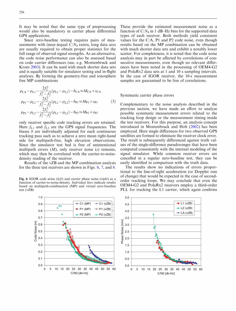
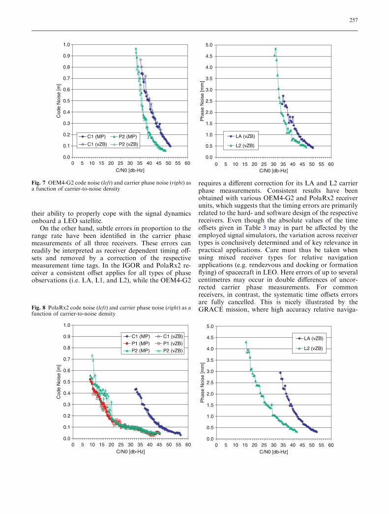
Results of the vZB and the MP combination analysisfor the three test receivers are shown in Figs. 6, 7, and 8.
These provide the estimated measurement noise as afunction of C/N0 in 1 dB–Hz bins for the supported datatypes of each receiver. Both methods yield consistentvalues for the C/A, P1 and P2 code noise, even thoughresults based on the MP combination can be obtainedwith much shorter data sets and exhibit a notably lowerscatter. For completeness, it is noted that the code noiseanalysis may in part be affected by correlations of con-secutive measurements, even though no relevant differ-ences have been noted in the processing of OEM4-G2and PolaRx2 data sets at 1 and 10 s sampling intervals.In the case of IGOR receiver, the 10-s measurementsamples are guaranteed to be free of correlations.
Systematic carrier phase errors
Complementary to the noise analysis described in theprevious section, we have made an effort to analyzepossible systematic measurement errors related to thetracking loop design or the measurement timing insidethe test receivers. For this purpose, an analysis conceptintroduced in Montenbruck and Holt (2002) has beenemployed. Here single differences for two observed GPSsatellites are formed to eliminate the receiver clock error.The result is subsequently differenced against truth val-ues of the single-difference pseudoranges that have beencomputed consistently with the internal modeling of thesignal simulator. While common receiver errors arecancelled in a regular zero-baseline test, they can beeasily identified in comparison with the truth data.
The results show no indications of errors propor-tional to the line-of-sight acceleration (or Doppler rateof change) that would be expected in the case of second-order tracking loops. We may conclude that even theOEM4-G2 and PolaRx2 receivers employ a third-orderPLL for tracking the L1 carrier, which again confirms
0.0
0.1
0.2
0.3
0.4
0.5
0.6
0.7
0.8
0.9
1.0
0 5 10 15 20 25 30 35 40 45 50 55 60C/N0 [db-Hz]
Cod
eN
oise
[m]
C1 (MP) C1 (vZB)
P1 (MP) P1 (vZB)
P2 (MP) P2 (vZB)
0.0
0.5
1.0
1.5
2.0
2.5
3.0
3.5
4.0
4.5
5.0
0 5 10 15 20 25 30 35 40 45 50 55 60C/N0 [db-Hz]
Pha
seN
oise
[mm
]
L1 (vZB)
L2 (vZB)
LA (vZB)
Fig. 6 IGOR code noise (left) and carrier phase noise (right) as afunction of carrier-to-noise-density. Individual lines indicate resultsbased on multipath-combination (MP) and virtual zero-baselinetest (vZB)
256
their ability to properly cope with the signal dynamicsonboard a LEO satellite.
On the other hand, subtle errors in proportion to therange rate have been identified in the carrier phasemeasurements of all three receivers. These errors canreadily be interpreted as receiver dependent timing off-sets and removed by a correction of the respectivemeasurement time tags. In the IGOR and PolaRx2 re-ceiver a consistent offset applies for all types of phaseobservations (i.e. LA, L1, and L2), while the OEM4-G2
requires a different correction for its LA and L2 carrierphase measurements. Consistent results have beenobtained with various OEM4-G2 and PolaRx2 receiverunits, which suggests that the timing errors are primarilyrelated to the hard- and software design of the respectivereceivers. Even though the absolute values of the timeoffsets given in Table 3 may in part be affected by theemployed signal simulators, the variation across receivertypes is conclusively determined and of key relevance inpractical applications. Care must thus be taken whenusing mixed receiver types for relative navigationapplications (e.g. rendezvous and docking or formationflying) of spacecraft in LEO. Here errors of up to severalcentimetres may occur in double differences of uncor-rected carrier phase measurements. For commonreceivers, in contrast, the systematic time offsets errorsare fully cancelled. This is nicely illustrated by theGRACE mission, where high accuracy relative naviga-
0.0
0.1
0.2
0.3
0.4
0.5
0.6
0.7
0.8
0.9
1.0
0 5 10 15 20 25 30 35 40 45 50 55 60
C/N0 [db-Hz]
Cod
eN
oise
[m]
C1 (MP) P2 (MP)
C1 (vZB) P2 (vZB)
0.0
0.5
1.0
1.5
2.0
2.5
3.0
3.5
4.0
4.5
5.0
0 5 10 15 20 25 30 35 40 45 50 55 60C/N0 [db-Hz]
Pha
seN
oise
[mm
]
LA (vZB)
L2 (vZB)
0.0
0.1
0.2
0.3
0.4
0.5
0.6
0.7
0.8
0.9
1.0
0 5 10 15 20 25 30 35 40 45 50 55 60C/N0 [db-Hz]
Cod
eN
oise
[m]
C1 (MP) C1 (vZB)P1 (MP) P1 (vZB)P2 (MP) P2 (vZB)
0.0
0.5
1.0
1.5
2.0
2.5
3.0
3.5
4.0
4.5
5.0
0 5 10 15 20 25 30 35 40 45 50 55 60C/N0 [db-Hz]
Pha
seN
oise
[mm
]
LA (vZB)
L2 (vZB)
Fig. 7 OEM4-G2 code noise (left) and carrier phase noise (right) asa function of carrier-to-noise density
Fig. 8 PolaRx2 code noise (left) and carrier phase noise (right) as afunction of carrier-to-noise density
257
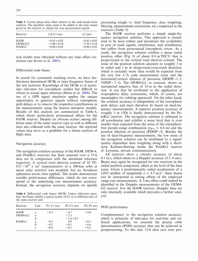
tion results were obtained without any time offset cor-rection (see Kroes et al. 2005).
Differential code biases
In search for systematic tracking errors, we have fur-thermore determined DCBs or inter-frequency biases ofthe test receivers. Knowledge of the DCBs is of partic-ular relevance for ionospheric studies but difficult toobtain in actual space missions (Heise et al. 2004). Theuse of a GPS signal simulator applies the uniqueopportunity to generate signals without ionosphericpath delays or to remove the respective contributions inthe measurements using the known simulator models.Results of this analysis are summarized in Table 4,which shows particularly pronounced offsets for theIGOR receiver. Despite an obvious scatter among dif-ferent units of the same receiver type as well as differentdata sets collected with the same receiver, the reportedvalues may serve as a guideline for a future analysis offlight data.
Navigation accuracy
The navigation solution accuracy of the IGOR, OEM-4,and PolaRx2 receivers has been assessed over a 15-hdata arc in comparison with the simulated referencetrajectory. A vertical total electron content of 10 TE-CU=1017 e)/m2 (representative of a 500-km orbit atmean solar activity) was modeled, but no broadcastephemeris errors were applied. The results demonstratenotable performance differences, which do not corre-spond to the underlying raw measurement accuracy.Instead, the navigation accuracy depends on specific
processing (single vs. dual frequency, data weighting,filtering, measurement corrections, etc.) employed in thereceivers (Table 5).
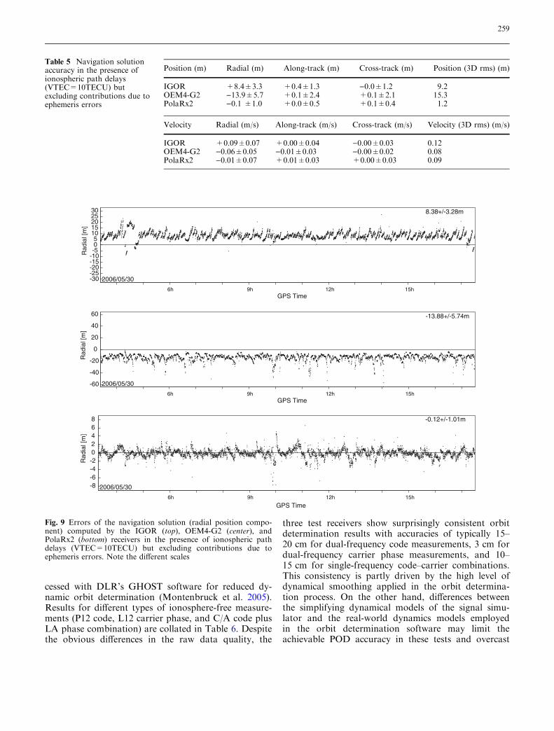
The IGOR receiver performs a simple single-fre-quency navigation solution. This approach is consid-ered to be most robust and maximizes the availabilityin case of weak signals, interference, and scintillation,but suffers from pronounced ionospheric errors. As aresult, the navigation solution exhibits a mean radialposition offset (Fig. 9) of about 0.8 m/TECU that isproportional to the vertical total electron content. Thenoise of the position solution amounts to roughly 3 min radial and 1 m in along-track/cross-track direction,which is certainly more than would be expected fromthe very low C/A code measurement noise and thehorizontal/vertical dilution of precision (HDOP�1–2,VDOP=2–3). The OEM4-G2, in contrast, shows anunexpected negative bias of 14 m in the radial direc-tion. It can best be attributed to the application oftropospheric delay corrections, which, of course, aremeaningless for orbiting spacecraft. On the other hand,the solution accuracy is independent of the ionosphericpath delays and must therefore be based on dual-fre-quency measurements. A superior position accuracy ofroughly 1 m (3D) is finally demonstrated by the Po-laRx2 receiver. The navigation solution is unbiased inall coordinates and exhibits a noise level that is evensmaller than expected from the noise of the ionosphere-free pseudo-range combination (rP12 � 0.6 m) and theposition dilution of precision (PDOP�3). Besides theuse of dual-frequency measurements, the low noise ofthe navigation solution can be attributed to a signal-quality dependent data weighting along with a short-term Kalman-filtering inside the PolaRx2 receiver(J. Leyssens, private communication).
All receivers show a velocity accuracy of about0.1 m/s, which relates to a Doppler accuracy of 2–4 cm/s.Biases may again be recognized for two receivers in theradial position component, albeit at the level of the datanoise. Given a predominantly radial acceleration of aLEO satellite of magnitude a � 8.5 m/s2, these biasescan be interpreted as timing offsets of the employedrange-rate measurements. A 5-ms offset could indeed beidentified in the Doppler measurements of the OEM4-G2 receiver. For the IGOR receiver, Doppler data areonly internally available which prevents a further anal-ysis.
POD performance
Complementary to the navigation solution accuracy,which is primarily of relevance for real-time and on-board applications, we assessed the precise orbitdetermination (POD) accuracy that can be achieved inpostprocessing. To this end, 15-h data arcs were pro-
Table 3 Carrier phase time offset relative to the code-based clocksolution. The specified values need to be added to the time stampgiven by the receiver to obtain the true measurement epoch
Receiver LA/L1 (ls) L2 (ls)
IGOR )0.45±0.05 )0.45±0.05OEM4-G2 )1.00±0.10 )3.10±0.10PolaRx2 )0.60±0.05 )0.60±0.05
Table 4 Differential code biases (DCB). Unless otherwise speci-fied, the biases exhibit a typical scatter of 0.1 m in different tests ofthe same receiver unit
Receiver Unit P1–C1 (m) P2–C1 (m) P2–P1 (m)
IGOR a +0.3 +4.7 +4.4OEM4-G2 a +2.3
b +1.6±0.2PolaRx2 a )0.3 0.0 +0.3
b )0.5 +0.1 +0.6c )0.4 +0.1 +0.5
258
cessed with DLR’s GHOST software for reduced dy-namic orbit determination (Montenbruck et al. 2005).Results for different types of ionosphere-free measure-ments (P12 code, L12 carrier phase, and C/A code plusLA phase combination) are collated in Table 6. Despitethe obvious differences in the raw data quality, the
three test receivers show surprisingly consistent orbitdetermination results with accuracies of typically 15–20 cm for dual-frequency code measurements, 3 cm fordual-frequency carrier phase measurements, and 10–15 cm for single-frequency code–carrier combinations.This consistency is partly driven by the high level ofdynamical smoothing applied in the orbit determina-tion process. On the other hand, differences betweenthe simplifying dynamical models of the signal simu-lator and the real-world dynamics models employedin the orbit determination software may limit theachievable POD accuracy in these tests and overcast
Table 5 Navigation solutionaccuracy in the presence ofionospheric path delays(VTEC=10TECU) butexcluding contributions due toephemeris errors
Position (m) Radial (m) Along-track (m) Cross-track (m) Position (3D rms) (m)
IGOR +8.4±3.3 +0.4±1.3 )0.0±1.2 9.2OEM4-G2 )13.9±5.7 +0.1±2.4 +0.1±2.1 15.3PolaRx2 )0.1 ±1.0 +0.0±0.5 +0.1±0.4 1.2
Velocity Radial (m/s) Along-track (m/s) Cross-track (m/s) Velocity (3D rms) (m/s)
IGOR +0.09±0.07 +0.00±0.04 )0.00±0.03 0.12OEM4-G2 )0.06±0.05 )0.01±0.03 )0.00±0.02 0.08PolaRx2 )0.01±0.07 +0.01±0.03 +0.00±0.03 0.09
2006/05/30
6h 9h 12h 15hGPS Time
-30-25-20-15-10-505
1015202530
Rad
ial [
m]
8.38+/-3.28m
2006/05/30
6h 9h 12h 15hGPS Time
-60
-40
-20
0
20
40
60
Rad
ial [
m]
-13.88+/-5.74m
2006/05/30
6h 9h 12h 15h
GPS Time
-8-6-4-202468
Rad
ial [
m]
-0.12+/-1.01m
Fig. 9 Errors of the navigation solution (radial position compo-nent) computed by the IGOR (top), OEM4-G2 (center), andPolaRx2 (bottom) receivers in the presence of ionospheric pathdelays (VTEC=10TECU) but excluding contributions due toephemeris errors. Note the different scales
259
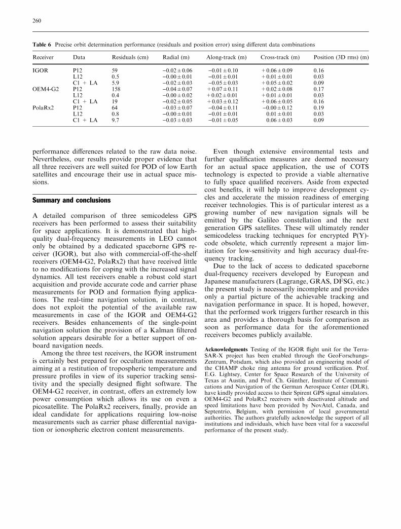
performance differences related to the raw data noise.Nevertheless, our results provide proper evidence thatall three receivers are well suited for POD of low Earthsatellites and encourage their use in actual space mis-sions.
Summary and conclusions
A detailed comparison of three semicodeless GPSreceivers has been performed to assess their suitabilityfor space applications. It is demonstrated that high-quality dual-frequency measurements in LEO cannotonly be obtained by a dedicated spaceborne GPS re-ceiver (IGOR), but also with commercial-off-the-shelfreceivers (OEM4-G2, PolaRx2) that have received littleto no modifications for coping with the increased signaldynamics. All test receivers enable a robust cold startacquisition and provide accurate code and carrier phasemeasurements for POD and formation flying applica-tions. The real-time navigation solution, in contrast,does not exploit the potential of the available rawmeasurements in case of the IGOR and OEM4-G2receivers. Besides enhancements of the single-pointnavigation solution the provision of a Kalman filteredsolution appears desirable for a better support of on-board navigation needs.
Among the three test receivers, the IGOR instrumentis certainly best prepared for occultation measurementsaiming at a restitution of tropospheric temperature andpressure profiles in view of its superior tracking sensi-tivity and the specially designed flight software. TheOEM4-G2 receiver, in contrast, offers an extremely lowpower consumption which allows its use on even apicosatellite. The PolaRx2 receivers, finally, provide anideal candidate for applications requiring low-noisemeasurements such as carrier phase differential naviga-tion or ionospheric electron content measurements.
Even though extensive environmental tests andfurther qualification measures are deemed necessaryfor an actual space application, the use of COTStechnology is expected to provide a viable alternativeto fully space qualified receivers. Aside from expectedcost benefits, it will help to improve development cy-cles and accelerate the mission readiness of emergingreceiver technologies. This is of particular interest as agrowing number of new navigation signals will beemitted by the Galileo constellation and the nextgeneration GPS satellites. These will ultimately rendersemicodeless tracking techniques for encrypted P(Y)-code obsolete, which currently represent a major lim-itation for low-sensitivity and high accuracy dual-fre-quency tracking.
Due to the lack of access to dedicated spacebornedual-frequency receivers developed by European andJapanese manufacturers (Lagrange, GRAS, DFSG, etc.)the present study is necessarily incomplete and providesonly a partial picture of the achievable tracking andnavigation performance in space. It is hoped, however,that the performed work triggers further research in thisarea and provides a thorough basis for comparison assoon as performance data for the aforementionedreceivers becomes publicly available.
Acknowledgments Testing of the IGOR flight unit for the Terra-SAR-X project has been enabled through the GeoForschungs-Zentrum, Potsdam, which also provided an engineering model ofthe CHAMP choke ring antenna for ground verification. Prof.E.G. Lightsey, Center for Space Research of the University ofTexas at Austin, and Prof. Ch. Gunther, Institute of Communi-cations and Navigation of the German Aerospace Center (DLR),have kindly provided access to their Spirent GPS signal simulators.OEM4-G2 and PolaRx2 receivers with deactivated altitude andspeed limitations have been provided by NovAtel, Canada, andSeptentrio, Belgium, with permission of local governmentalauthorities. The authors gratefully acknowledge the support of allinstitutions and individuals, which have been vital for a successfulperformance of the present study.
Table 6 Precise orbit determination performance (residuals and position error) using different data combinations
Receiver Data Residuals (cm) Radial (m) Along-track (m) Cross-track (m) Position (3D rms) (m)
IGOR P12 59 )0.02±0.06 )0.01±0.10 +0.06±0.09 0.16L12 0.5 )0.00±0.01 )0.01±0.01 +0.01±0.01 0.03C1 + LA 5.9 )0.02±0.03 )0.05±0.03 +0.05±0.02 0.09
OEM4-G2 P12 158 )0.04±0.07 +0.07±0.11 +0.02±0.08 0.17L12 0.4 )0.00±0.02 +0.02±0.01 +0.01±0.01 0.03C1 + LA 19 )0.02±0.05 +0.03±0.12 +0.06±0.05 0.16
PolaRx2 P12 64 )0.03±0.07 )0.04±0.11 )0.00±0.12 0.19L12 0.8 )0.00±0.01 )0.01±0.01 0.01±0.01 0.03C1 + LA 9.7 )0.03±0.03 )0.01±0.05 0.06±0.03 0.09
260
References
Ardaens J-S (2005) Experimental analysisof a choke ring antenna; DLR-GSOCTN 05-05. Deutsches Zentrum fur Luft-und Raumfahrt, Oberpfaffenhofen
BRE (2003) Integrated GPS occultationreceiver IGOR; data sheet. BroadreachEngineering, Tempe, Arizona
Buist P (2002) NEC/Toshiba Space Sys-tems’ spaceborne GPS receivers. In:Presented at NEC/Toshiba, December2002, Yokohama
Fenton PC, Petersen WD (1998) Dual fre-quency global positioning system. USPatent 5736961, April 7, 1998
Gurtner W, Estey L (2002) RINEX Version2.20—modifications to accommodatelow earth orbiter data; April 15, 2002.URL http://ftp.unibe.ch/aiub/rinex/rnx_leo.txt
Heise S, Stolle C, Schluter S, Jakowski N(2004) Differential code bias of GPSreceivers in low earth orbit: an assess-ment for CHAMP and SAC-C. In:Reigber CH, Luhr H, Schwintzer P,Wickert J (eds) CHAMP mission resultsfor gravity and magnetic field mapping,and GPS atmosphere sounding.Springer, Berlin Heidelberg New York
Kroes R, Montenbruck O, Bertiger W,Visser P (2005) Precise GRACE base-line determination using GPS. GPSSolutions 9:21–31 DOI 10.1007/s10291-004-0123-5
Kursinski ER, Hajj GA, Hardy KR,Schofield JT, Linfield RP (1997)Observing Earth’s atmosphere withradio occultation measurements usingthe global positioning system. J Geo-phys Res 102/D19:23429–23465
Langley RB, Montenbruck O, MarkgrafM, Kang CS, Kim D (2004) Qualifica-tion of a commercial dual-frequencyGPS receiver for the e-POP platformonboard the Canadian CASSIOPEspacecraft. In: Second ESA workshopon satellite navigation user equipmenttechnologies, NAVITEC’2004, Decem-ber 8–10, 2004, Noordwijk, The Neth-erlands
Lear WM (1987) GPS navigation for low-earth orbiting vehicles; NASA 87-FM-2, Rev. 1; JSC-32031, Lyndon B.Johnson Space Center, Houston
Leyssens J, Markgraf M (2005) Evaluationof a commercial-off-the-shelf dual-fre-quency GPS receiver for use on LEOsatellites. In: ION GNSS 2005 confer-ence, September 13–16, 2005, LongBeach, California
Markgraf M, Montenbruck O (2004) Totalionizing dose testing of the NovAtelOEM4-G2L GPS receiver; DLR-GSOCTN 04-04. Deutsches Zentrum fur Luft-und Raumfahrt, Oberpfaffenhofen
Marradi L, Banfi E, Mambretti A (2001)The Lagrange receiver: designand in-flight demonstration.NAVITECH’2001, December 10–12,2001, Noordwijk
Meehan TK, Thomas JB Jr, Young LE(2000) P-code enhanced method forprocessing encrypted GPS signals with-out knowledge of the encryption code.US Patent 6061390, May 9, 2000
Montenbruck O, Holt G (2002) SpaceborneGPS receiver performance testing;DLR-GSOC TN 02-04. DeutschesZentrum fur Luft- und Raumfahrt,Oberpfaffenhofen
Montenbruck O, Kroes R (2003) In-flightperformance analysis of the CHAMPBlackJack receiver. GPS Solut 7:74–86
Montenbruck O, van Helleputte T, KroesR, Gill E (2005) Reduced dynamic orbitdetermination using GPS code andcarrier measurements. Aerospace SciTechnol 9/3:261–271 DOI 10.1016/j.ast.2005.01.003
Rankin D, Kekez DD, Zee RE, PranajayaFM, Foisy DG, Beattie AM (2004) TheCanX-2 nanosatellite: expanding thescience abilities of nanosatellites. In:Proceedings of the 55th InternationalAstronautical Congress, October 2004,Vancouver, Canada
Reigber CH, Jochmann H, Wunsch J, Pet-rovic S, Schwintzer P, Barthelmes F,Neumayer K-H, Konig R, Forste CH,Balmino G, Biancale R, Lemoine J-M,Loyer S, Perosanz F (2004) Earthgravity field and seasonal variabilityfrom CHAMP. In: Reigber CH, LuhrH, Schwintzer P, Wickert J (eds) Earthobservation with CHAMP—resultsfrom three years in orbit. Springer,Berlin Heidelberg New York, pp 25–30
Silvestrin P, Cooper J (2000) Method ofprocessing of signals of a satellite posi-tioning system. US Patent 6157341,December 5, 2000
Silvestrin P, Bagge R, Bonnedal M, Carls-trom A, Christensen J, Hagg M, Lind-gren T, Zangerl F (2000) SpaceborneGNSS radio occultation instrumenta-tion for operational applications. In:ION-GPS-2000 conference, Salt LakeCity, September 19–22, 2000, pp 872–880
Spirent (2004) SimGEN (including SimLo-cate) user manual—software for theSpirent range of satellite navigationsimulator products; DGP00686AAA;Issue 1–13, August 2004
Thomas JB (1995) Signal-processing theoryfor the TurboRogue receiver. JPLPublication 95–6, April 1, 1995
Van Dierendonck AJ (1995) GPS receivers.In: Spilker J, Parkinson B (eds) Globalpositioning system: theory and applica-tions, vol I, chapt. 8. American Instituteof Aeronautics and Astronautics Inc.,Washington
Williams J, Lightsey EG, Yoon SP, SchutzRE (2002) Testing of the ICESatBlackJack GPS receiver engineeringmodel. In: ION-GPS-2002 conference,September 24–27, 2002, Portland, Ore-gon
Woo KT (2000) Optimum semi-codelesscarrier phase tracking of L2. Naviga-tion: J Inst Navigation 47(2):82
Wu B-H, Chu V, Chen P, Ting TH (2005)FORMOSAT-3/COSMIC science mis-sion update. GPS Solut 9:111–121
Yunck TP (2004) Spaceborne GPS for PODand earth science. In: Reigber CH, LuhrH, Schwintzer P, Wickert J (eds) Earthobservation with CHAMP— resultsfrom three years in orbit. Springer,Berlin Heidelberg New York, pp 25–30
261