Embed Size (px)
Citation preview

Performance Evaluation of Free Vibration of Laminated Composite
Stiffened Hyperbolic Paraboloid Shell Panel with Cutout
Sarmila Sahoo
Department of Civil Engineering, Heritage Institute of Technology, Kolkata 700107, India
E-mail: [email protected], [email protected]
Keywords: laminated composites; hyperbolic paraboloid shell panel; cutout; stiffener; free vibration; finite element.
Abstract. The paper considers free vibration characteristics of stiffened composite hyperbolic
paraboloid shell panel with cutout in terms of natural frequency and mode shapes. A finite element
code is developed for the purpose by combining an eight noded curved shell element with a three
noded curved beam element. The size of the cutouts and their positions with respect to the shell
centre are varied for different edge conditions of cross-ply and angle-ply laminated shells. The
effects of these parametric variations on the fundamental frequencies and mode shapes are
considered in details to conclude a set of inferences of practical engineering significance.
Notations
a ,b length and width of shell in plan / /,a b length and width of cutout in plan
bst width of stiffener in general
bsx, bsy width of x and y stiffeners respectively
Bsx, Bsy strain displacement matrix of stiffener elements
dst depth of stiffener in general
dsx, dsy depth of x and y stiffeners respectively
{de} element displacement
esx, esy eccentricities of x and y -stiffeners with respect to shell mid-surface respectively
E11, E22 elastic moduli
G12, G13, G23 shear moduli of a lamina with respect to 1, 2 and 3 axes of fibre
h shell thickness
Mx, My moment resultants
Mxy torsion resultant
np number of plies in a laminate
N1-N8 shape functions
Nx, Ny inplane force resultants
Nxy inplane shear resultant
Qx, Qy transverse shear resultant
Rxx, Ryy, Rxy radii of curvature and cross curvature of shell respectively
u, v, w translational degrees of freedom
x, y, z local co-ordinate axes
X, Y, Z global co-ordinate axes
zk distance of bottom of the kth ply from mid-surface of a laminate
, rotational degrees of freedom
x, y inplane strain component
xy ,xz, yz shearing strain components
12, 21 Poisson’s ratios
, , isoparametric co-ordinates
density of material
International Journal of Engineering and Technologies Submitted: 2016-02-09ISSN: 2297-623X, Vol. 7, pp 1-24 Accepted: 2016-03-22doi:10.18052/www.scipress.com/IJET.7.1 Online: 2016-05-16© 2016 SciPress Ltd., Switzerland
SciPress applies the CC-BY 4.0 license to works we publish: https://creativecommons.org/licenses/by/4.0/
x, y inplane stress components
xy, xz, yz shearing stress components
natural frequency
non-dimensional natural frequency
2/12
22
2 / hEa
Introduction
Composite shell structures are extensively used in aerospace, civil, marine and other
engineering applications. In practical civil engineering applications, the necessity of covering large
column free open areas is often an issue. It is advantageous to use thin shells instead of flat plates to
cover large column free open spaces as in airports, parking lots, hangers, and the like. Such areas in
medical plants and automobile industries prefer entry of north light through the roofing units. Quite
often, to save weight and also to provide a facility for inspection, cutouts are provided in shell
panels. In practice the margin of the cutouts must be stiffened to take account of stress concentration
effects. In civil engineering construction, conoidal hyperbolic paraboloid (among the anticlastic) and
elliptic paraboloid (among the synclastic) shells are used as roofing units to cover large column free
areas. The hyperbolic paraboloid shells are aesthetically appealing although they offer less stiffness
than other doubly curved shells. Now-a-days, civil engineers use laminated composites to fabricate
these shell forms as the high specific stiffness and strength properties of these materials result in
less gravity forces and mass-induced forces (seismic force) on the laminated shells compared to
their isotropic counterparts. All these taken together reduce the foundation costs to a great extent.
Realizing the importance of laminated composite doubly curved shells in the industry, several
aspects of shell behaviour such as bending, buckling, vibration, impact etc. are being reported by
different researchers. The present investigation is however, restricted only to the free vibration
behaviour of composite stiffened hyperbolic paraboloid shell panels with cutout.
No wonder a number of researchers are working to explore different behavioral aspects of
laminated doubly curved shells. Researchers like Ghosh and Bandyopadhyay [1], Dey et al. [2, 3],
Chakravorty et al. [4, 5] reported static and dynamic behaviour of laminated doubly curved shells.
Later Nayak and Bandyopadhyay [6-8], Das and Chakravorty [9-12] and Pradyumna and
Bandyopadhyay [13, 14] reported static, dynamic and instability behaviour of laminated doubly
curved shells. Application of doubly curved shells in structures often necessitates provision of
cutouts for the passage of light, service lines and also sometimes for alteration of the resonant
frequency. The free vibration of composite as well as isotropic plate with cutout was studied by
different researchers from time to time. Reddy [15] investigated large amplitude flexural vibration
of composite plate with cutout. Malhotra et al. [16] studied free vibration of composite plate with
cutout for different boundary conditions. One of the early reports on free vibration of curved panels
with cutout was due to Sivasubramonian et al. [17]. They analysed the effect of cutouts on the
natural frequencies of plates with some classical boundary conditions. The plate had a curvature in
one direction and was straight in the other. The effect of fibre orientation and size of cutout on
natural frequency on orthotropic square plates with square cutout was studied using Rayleigh-Ritz
method. Later Sivakumar et al. [18], Rossi [19], Huang and Sakiyama [20] and Hota and Padhi [21]
studied free vibration of plate with various cutout geometries. Chakravorty et al. [22] analysed the
effect of concentric cutout on different shell options. Sivasubramonian et al. [23] studied the effect
of curvature and cutouts on square panels with different boundary conditions. The size of the cutout
(symmetrically located) as well as curvature of the panels is varied. Hota and Chakravorty [24]
published useful information about free vibration of stiffened conoidal shell roofs with cutout. Later
Nanda and Bandyopadhyay [25], Kumar et al. [26] studied the effect of different parametric
variation on free vibration of cylindrical shell with cutout using first order shear deformation theory
(FSDT) and higher order shear deformation theory (HYSD) respectively.
2 Volume 7
It is noted from the literature review that free vibration study of laminated composite
hyperbolic paraboloid shell panels with cutout is not reported by any researcher so far although the
importance of this shell form is mentioned. Thus the present study intends to study the free vibration
behaviour of stiffened hyperbolic paraboloid shell panels with cutout by varying the size and
position of the cutouts.
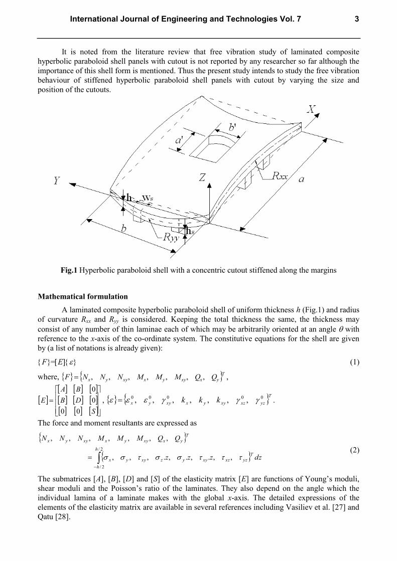
Fig.1 Hyperbolic paraboloid shell with a concentric cutout stiffened along the margins
Mathematical formulation
A laminated composite hyperbolic paraboloid shell of uniform thickness h (Fig.1) and radius
of curvature Rxx and Ryy is considered. Keeping the total thickness the same, the thickness may
consist of any number of thin laminae each of which may be arbitrarily oriented at an angle with
reference to the x-axis of the co-ordinate system. The constitutive equations for the shell are given
by (a list of notations is already given):
F=E (1)
where, Tyxxyyxxyyx QQMMMNNNF ,,,,,,, ,
S
DB
BA
E
00
0
0
, T
yzxzxyyxxyyx kkk 00000 ,,,,,,, .
The force and moment resultants are expressed as
2/
2/
,,.,.,.,,,
,,,,,,,
h
h
T
yzxzxyyzxyyx
T
yxxyyxxyyx
dzzzz
QQMMMNNN
(2)
The submatrices [A], [B], [D] and [S] of the elasticity matrix [E] are functions of Young’s moduli,
shear moduli and the Poisson’s ratio of the laminates. They also depend on the angle which the
individual lamina of a laminate makes with the global x-axis. The detailed expressions of the
elements of the elasticity matrix are available in several references including Vasiliev et al. [27] and
Qatu [28].
International Journal of Engineering and Technologies Vol. 7 3
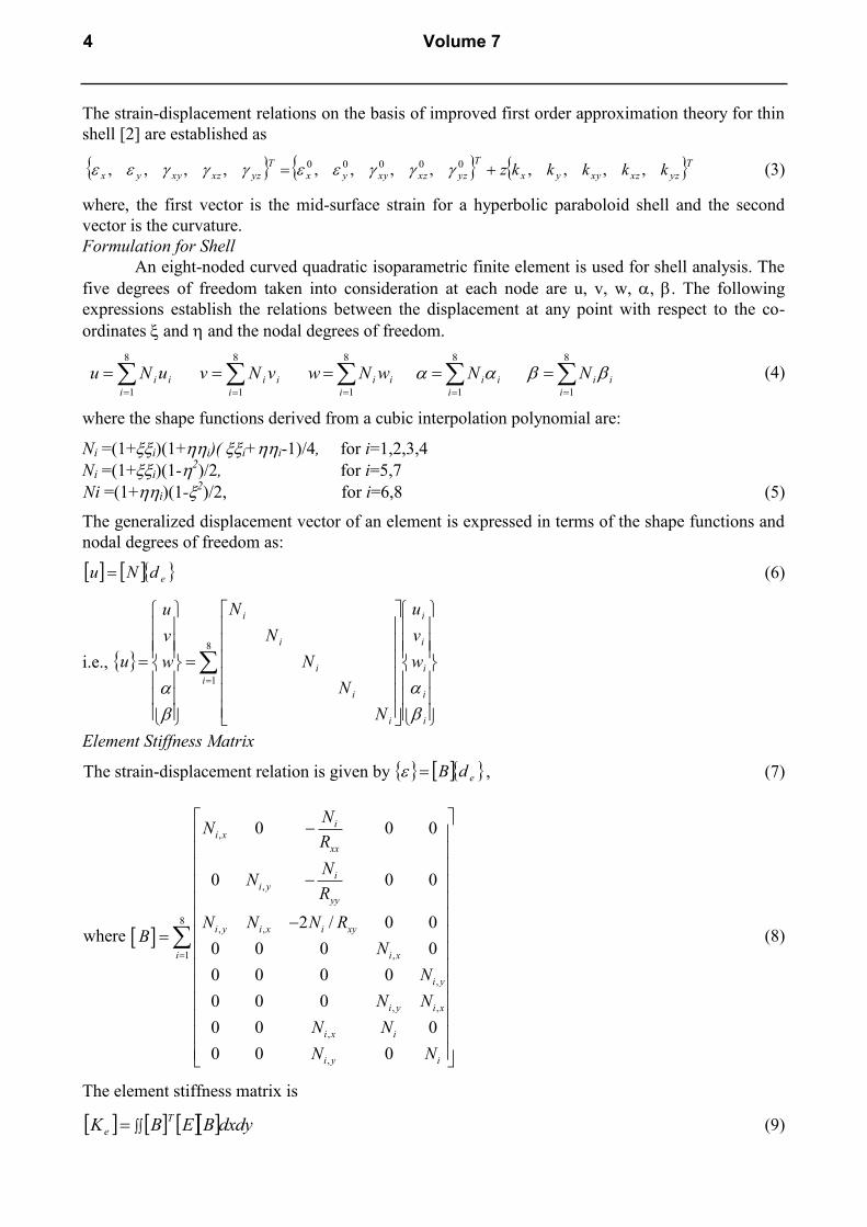
The strain-displacement relations on the basis of improved first order approximation theory for thin
shell [2] are established as
Tyzxzxyyx
T
yzxzxyyx
T
yzxzxyyx kkkkkz ,,,,,,,,,,,, 00000 (3)
where, the first vector is the mid-surface strain for a hyperbolic paraboloid shell and the second
vector is the curvature.
Formulation for Shell
An eight-noded curved quadratic isoparametric finite element is used for shell analysis. The
five degrees of freedom taken into consideration at each node are u, v, w, , . The following
expressions establish the relations between the displacement at any point with respect to the co-
ordinates and and the nodal degrees of freedom.
i
i
i uNu
8
1
i
i
i vNv
8
1
i
i
i wNw
8
1
i
i
iN
8
1
i
i
iN
8
1
(4)
where the shape functions derived from a cubic interpolation polynomial are:
Ni =(1+i)(1+i)( i+i-1)/4, for i=1,2,3,4
Ni =(1+i)(1-2)/2, for i=5,7
Ni =(1+i)(1-2)/2, for i=6,8 (5)
The generalized displacement vector of an element is expressed in terms of the shape functions and
nodal degrees of freedom as:
edNu (6)
i.e.,
8
1i
i
i
i
i
i
i
i
i
i
i
w
v
u
N
N
N
N
N
w
v
u
u
Element Stiffness Matrix
The strain-displacement relation is given by edB , (7)
where
,
,
8, ,
1 ,
,
, ,
,
,
0 0 0
0 0 0
2 / 0 0
0 0 0 0
0 0 0 0
0 0 0
0 0 0
0 0 0
ii x
xx
ii y
yy
i y i x i xy
i i x
i y
i y i x
i x i
i y i
NN
R
NN
R
N N N RB
N
N
N N
N N
N N
(8)
The element stiffness matrix is
dxdyBEBKT
e (9)
4 Volume 7

Element Mass Matrix
The element mass matrix is obtained from the integral
dxdyNPNMT
e , (10)
where,
8
1
0000
0000
0000
0000
0000
i
i
i
i
i
i
N
N
N
N
N
N ,
8
1
0000
0000
0000
0000
0000
i
I
I
P
P
P
P ,
in which
np
k
z
z
k
k
dzP1
1
and
1
2
1
k
k
znp
k z
I z dz
(11)
Formulation for Stiffener
Three noded curved isoparametric beam elements are used to model the stiffeners, which are
taken to run only along the boundaries of the shell elements. In the stiffener element, each node has
four degrees of freedom i.e. usx, wsx, sx and sx for x-stiffener and vsy, wsy, sy and sy for y-stiffener.
The generalized force-displacement relation of stiffeners can be expressed as:
x-stiffener: sxisxsxsxsxsx BDDF ;
y-stiffener: syisysysysysy BDDF (12)
where, Tsxxzsxxsxxsxxsx QTMNF ; Txsxsxxsxxsxxsxsx wu ....
and Tsyyzsyysyysyysy QTMNF ; Tysysyysyysyysysy wv ....
The generalized displacements of the x-stiffener and the shell are related by the transformation
matrix sxi xT where
1
0 1
0 0 1
0 0 0 1
sx
xx
x
esymmetric
R
T
(13)
The generalized displacements of the y-stiffener and the shell are related by the transformation
matrix syi yT where
1
0 1
0 0 1
0 0 0 1
sy
yy
y
esymmetric
R
T
(14)
These transformations are required due to curvature of x-stiffener and y-stiffener. In the above
equations, esx and esy are the eccentricities of the x-stiffener and y-stiffener. is the appropriate
portion of the displacement vector of the shell.
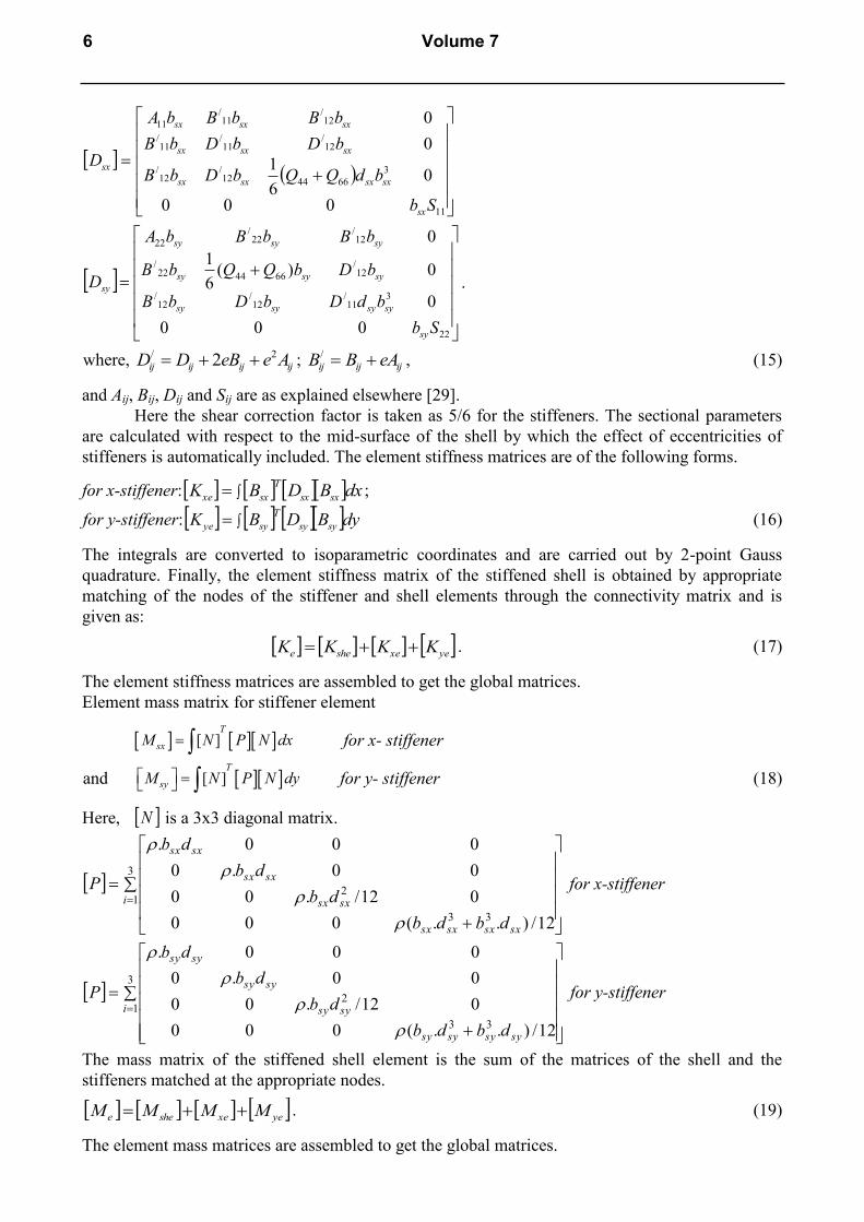
Elasticity matrices are as follows:
International Journal of Engineering and Technologies Vol. 7 5
11
3
664412/
12/
12/
11/
11/
12/
11/
11
000
06
1
0
0
Sb
bdQQbDbB
bDbDbB
bBbBbA
D
sx
sxsxsxsx
sxsxsx
sxsxsx
sx
22
311
/12
/12
/
12/
664422/
12/
22/
22
000
0
0)(6
1
0
Sb
bdDbDbB
bDbQQbB
bBbBbA
D
sy
sysysysy
sysysy
sysysy
sy .
where, ijijijij AeeBDD 2/ 2 ; ijijij eABB /, (15)
and Aij, Bij, Dij and Sij are as explained elsewhere [29].
Here the shear correction factor is taken as 5/6 for the stiffeners. The sectional parameters
are calculated with respect to the mid-surface of the shell by which the effect of eccentricities of
stiffeners is automatically included. The element stiffness matrices are of the following forms.
for x-stiffener: dxBDBK sxsx
T
sxxe ;
for y-stiffener: dyBDBK sysy
T
syye (16)
The integrals are converted to isoparametric coordinates and are carried out by 2-point Gauss
quadrature. Finally, the element stiffness matrix of the stiffened shell is obtained by appropriate
matching of the nodes of the stiffener and shell elements through the connectivity matrix and is
given as:
yexeshee KKKK . (17)
The element stiffness matrices are assembled to get the global matrices.
Element mass matrix for stiffener element
[ ]T
sxM N P N dx for x- stiffener
and [ ]T
syM N P N dy for y- stiffener (18)
Here, N is a 3x3 diagonal matrix.
3
1
33
2
12/)..(000
012/.00
00.0
000.
i
sxsxsxsx
sxsx
sxsx
sxsx
dbdb
db
db
db
P
for x-stiffener
3
1
33
2
12/)..(000
012/.00
00.0
000.
i
sysysysy
sysy
sysy
sysy
dbdb
db
db
db
P
for y-stiffener
The mass matrix of the stiffened shell element is the sum of the matrices of the shell and the
stiffeners matched at the appropriate nodes.
yexeshee MMMM . (19)
The element mass matrices are assembled to get the global matrices.
6 Volume 7

Cutout consideration
The code developed can take the position and size of cutout as input. The program is capable
of generating non uniform finite element mesh all over the shell surface. So the element size is
gradually decreased near the cutout margins. Such finite element mesh is redefined in steps and a
particular grid is chosen to obtain the fundamental frequency when the result does not improve by
more than one percent on further refining. Convergence of results is ensured in all the problems
taken up here.
Solution Procedure
The free vibration analysis involves determination of natural frequencies from the condition
02 MK (20)
This is a generalized eigen value problem and is solved by the subspace iteration algorithm.
Results and discussion
First the validation study of the proposed finite element shell model in presence of cutout is
carried out. The results of Table 1 show that the agreement of present results with the earlier ones is
excellent and the correctness of the stiffener formulation is established. Free vibration of corner
point supported, simply supported and clamped spherical shells of (0/90)4 lamination with cutouts is
also considered. The fundamental frequencies of spherical shell with cutout obtained by the present
method agree well with those reported by Chakravorty et al. [22] as evident from Table 2,
establishing the correctness of the cutout formulation in doubly curved shells. Thus it is evident that
the finite element model proposed here can successfully analyze vibration problems of stiffened
composite hyperbolic paraboloid shell panels with cutout which is reflected by close agreement of
present results with benchmark ones.
Table 1: Natural frequency (Hz) of centrally stiffened clamped square plate
Mode no. Mukherjee and
Mukhopadhyay [31]
Nayak and
Bandyopadhyay [32]
Present method
N8
(FEM)
N9
(FEM)
1 711.8 725.2 725.1 733
a=b=0.2032 m, shell thickness =0.0013716 m, stiffener depth 0.0127 m, stiffener width=0.00635 m,
stiffener eccentric at bottom, Material property: E=6.87x10¹⁰
N/m2, =0.29, =2823 kg/m
3
Table 2: Non-dimensional Fundamental Frequencies ( ) for laminated composite spherical shell
with cutout
a/b=1, a/h=100, a//b
/=1, h/Rxx= h/Ryy=1/300, CS=Corner point supported, SS=Simply supported,
CL=Clamped
In order to study the effect of cutout size and position on the free vibration response
additional problems for hyperbolic paraboloid shell panels with 0/90/0/90 and +45/-45/+45/-45
lamination and different boundary conditions have been solved. The positions of the cutouts are
varied along both of the plan directions of the shell for different practical boundary conditions to
study the effect of eccentricity of cutout on the fundamental frequency.
a’/a CS SS CL
Chakravorty
et. al.[22]
Present
model
Chakravorty
et. al.[22]
Present
model
Chakravorty
et. al.[22]
Present
model
0.0 34.948 34.601 47.109 47.100 118.197 117.621
0.1 35.175 35.926 47.524 47.114 104.274 104.251
0.2 36.528 36.758 48.823 48.801 98.299 97.488
0.3 37.659 37.206 50.925 50.920 113.766 113.226
0.4 39.114 39.412 53.789 53.788 110.601 110.094
International Journal of Engineering and Technologies Vol. 7 7

Behavior of shell panel with concentric cutout
Tables 3 and 4 furnish the results of non-dimensional frequency ( ) of 0/90/0/90 and +45/-
45/+45/-45 stiffened hyperbolic paraboloid shells with cutout. The shells considered are of square
plan form (a=b) and the cutouts are also taken to be square in plan (a/=b
/). The cutouts placed
concentrically on the shell surface. The cutout sizes (i.e. a//a) are varied from 0 to 0.4 and boundary
conditions are varied along the four edges. The stiffeners are place along the cutout periphery and
extended up to the edge of the shell. The boundary conditions are designated by describing the
support clamped or simply supported as C or S taken in an anticlockwise order from the edge x=0.
This means a shell with CSCS boundary is clamped along x=0, simply supported along y=0 and
clamped along x=a and simply supported along y=b.
Effect of cutout size on fundamental frequency
From Tables 3 and 4 it is seen that when a cutout is introduced to a stiffened shell the
fundamental frequency increases in all the cases. This increasing trend is noticed for both cross ply
and angle ply shells. This initial increase in frequency is due to the fact that with the introduction of
cutout, numbers of stiffeners are increase from two to four in the present study. It is evident from
Tables 3 and 4 that in all the cases with the introduction of cutout with a//a=0.3 the frequencies
increase. But further increase in cutout size, fundamental frequencies decrease in few cases. When
the cutout size is further increased, but the number and dimensions of the stiffeners do not change,
the shell surface undergoes loss of both mass and stiffness as a result fundamental frequency may
increase or decrease. As with the introduction of a cutout of a//a=0.3, in shell surface, the frequency
increases in all the cases, this leads to the engineering conclusion that concentric cutouts with
stiffened margins may be provided safely on shell surfaces for functional requirements upto
a//a=0.3.
Table 3: Non-dimensional fundamental frequencies ( ) for laminated composite (0/90/0/90)
stiffened hyperbolic paraboloid shell for different sizes of the central square cutout and different
boundary conditions
Boundary
conditions Cutout size (
/a a )
0 0.1 0.2 0.3 0.4
CCCC 103.94 118.21 142.85 155.42 157.23
CSCC 82.21 97.37 117.73 133.23 129.29
CCSC 84.52 96.86 115.87 133.89 137.92
CCCS 81.95 96.1 117.23 132.71 129.06
CSSC 66.1 77.91 94.04 109.39 109.2
CCSS 66.04 77.73 94.02 109.38 109.17
CSCS 92.07 91.93 114.27 130.15 127.7
SCSC 90.59 93.61 114.08 131.02 132.55
CSSS 61.19 73.11 90.99 104.18 104.03
SSSC 62.26 74.04 94.4 103.78 102.22
SSCS 61.19 73.18 90.99 104.18 104.03
SSSS 66.21 68.82 88.25 97.8 96.83
Point
supported
28.56 33.64 40.85 49.17 57.67
a/b=1, a/h=100, / /a b =1, c/a=0.2; E11/E22 = 25, G23 = 0.2E22, G13 = G12 = 0.5E22, 12 =21 =0.25.
8 Volume 7

Effect of boundary conditions
The boundary conditions may be arranged in the following order, considering number of
boundary constraints: CCCC, CSCC, CCSC, CCCS, CSSC, CCSS, CSCS, SCSC, CSSS, SSSC,
SSCS, SSSS and Corner Point supported. Tables 5 and 6 show the efficiency of a particular
clamping option in improving the fundamental frequency of a shell panel with minimum number of
boundary constraints relative to that of a clamped shell. Marks are assigned to each boundary
combination in a scale assigning a value of 0 to the frequency of a corner point supported shell and
100 to that of a fully clamped shell. These marks are furnished for cutouts with a//a=0.2 These
tables will enable a practicing engineer to realize at a glance the efficiency of a particular boundary
condition in improving the frequency of a shell, taking that of clamped shell as the upper limit.
Table 4: Non-dimensional fundamental frequencies ( ) for laminated composite
(+45/-45/+45/-45) stiffened hyperbolic paraboloid shell for different sizes of the central square
cutout and different boundary conditions
Boundary
conditions Cutout size (
/a a )
0 0.1 0.2 0.3 0.4
CCCC 101.36 119.09 123.64 126.15 129.41
CSCC 91.93 108.2 114.13 115.26 113.36
CCSC 94.41 108.5 113.84 116.84 119.99
CCCS 91.7 107.51 113.95 115.13 113.35
CSSC 84.44 96.76 105.31 108.66 108.55
CCSS 83.77 96.27 105.06 108.64 108.7
CSCS 90.06 105.92 111.18 112.05 110.86
SCSC 92.44 106.55 111.01 113.69 116.84
CSSS 82.22 93.92 102.95 105.28 105.35
SSSC 81.12 95.43 102.26 105.14 105.35
SSCS 82.35 94.2 102.95 105.28 105.35
SSSS 73.24 90.05 96.76 99.26 99.61
Point
supported
36.17 42.04 49.86 59.38 61.29
a/b=1, a/h=100, / /a b =1, c/a=0.2; E11/E22 = 25, G23 = 0.2E22, G13 = G12 = 0.5E22, 12 =21 =0.25.
Table 5: Clamping options for 0/90/0/90 hyperbolic paraboloid shells with central cutouts having
a//a ratio 0.2.
Number of
sides to be
clamped
Clamped edges Improvement of
frequencies with respect
to point supported shells
Marks indicating
the efficiencies of
no of restraints
0 Corner Point supported - 0
0 Simply supported no edges
clamped (SSSS)
Good improvement 46
1 a) hyperbolic edge along x=a
(SSCS)
Good improvement 49
b)hyperbolic edge along x=0
(CSSS)
Good improvement 49
b) One parabolic edge along
y= b (SSSC)
Good improvement 53
2 a)Two hyperbolic edges x=0
and x=a (CSCS)
Marked improvement 72
b)Two parabolic edges along
y=0 and y=b(SCSC)
Marked improvement 72
International Journal of Engineering and Technologies Vol. 7 9

c)Any two edges except the
above option (CSSC,CCSS)
Good improvement 52
3 3 edges including the two
hyperbolic edges
(CSCC,CCCS)
Marked improvement 75
3 edges excluding the
hyperbolic edge along x=a
(CCSC)
Marked improvement 74
4 All sides (CCCC) Frequency attains
highest value
100
Table 6: Clamping options for +45/-45/+45/-45 hyperbolic paraboloid shells with central cutouts
having a//a ratio 0.2.
Number of
sides to be
clamped
Clamped edges Improvement of
frequencies with respect
to point supported shells
Marks indicating the
efficiencies of no of
restraints
0 Corner Point supported - 0
0 Simply supported no edges
clamped (SSSS)
Marked improvement 64
1 a) hyperbolic edge along x=a
(SSCS)
Marked improvement 72
b)hyperbolic edge along x=0
(CSSS)
Marked improvement 72
b) One parabolic edge along
y= b (SSSC)
Marked improvement 71
2 a)Two hyperbolic edges x=0
and x=a (CSCS)
Remarkable
improvement
83
b)Two parabolic edges along
y=0 and y=b(SCSC)
Remarkable
improvement
83
c)Any two edges except the
above option (CSSC,CCSS)
Marked improvement 75
3 3 edges including the two
hyperbolic edges
(CSCC,CCCS)
Remarkable
improvement
87
3 edges excluding the
hyperbolic edge along x=a
(CCSC)
Remarkable
improvement
87
4 All sides (CCCC) Frequency attains highest
value
100
It is seen from Table 5 and 6, that fundamental frequencies of members belonging to same
number of boundary constraints may not have close values for all the cases considered here. So the
boundary constraint is not the sole criteria for its performance. The free vibration characteristics
mostly depends on the arrangement of boundary constrains rather than their actual number, is
evident from the present study. It can be seen from the present study that if the hyperbolic edge
along x=a is released from clamped to simply supported, the change of frequency is more in case of
a cross ply shells than that for an angle ply shells. Again, if the two adjacent edges are released,
fundamental frequency decreases more significantly than that of a shell in which two alternate edges
are released. This is true for both cross and angle ply shells. For cross ply shells if three or four
edges are simply supported, frequency values undergo marked decrease but for angle ply shells with
the introduction of more number of simply supported edges the frequency value does not change so
10 Volume 7

drastically. The results indicate that two alternate edges should preferably be clamped in order to
achieve higher frequency values.
Fig.2: First mode shapes of laminated composite (0/90/0/90) stiffened hyperbolic paraboloid shell
for different sizes of the central square cutout and boundary conditions.
Mode shapes
The mode shapes corresponding to the fundamental modes of vibration are plotted in Fig.2
and Fig.3 for cross-ply and angle ply shells respectively. The normalized displacements are drawn
with the shell mid-surface as the reference for all the support condition and for all the lamination
used here. The fundamental mode is clearly a bending mode or torsion mode for all the boundary
condition for cross ply and angle ply shells, except corner point supported shell. For corner point
supported shells the fundamental mode shapes are complicated. With the introduction of cutout
mode shapes remain almost similar. When the size of the cutout is increased from 0.2 to 0.4 the
fundamental modes of vibration do not change to an appreciable amount.
International Journal of Engineering and Technologies Vol. 7 11
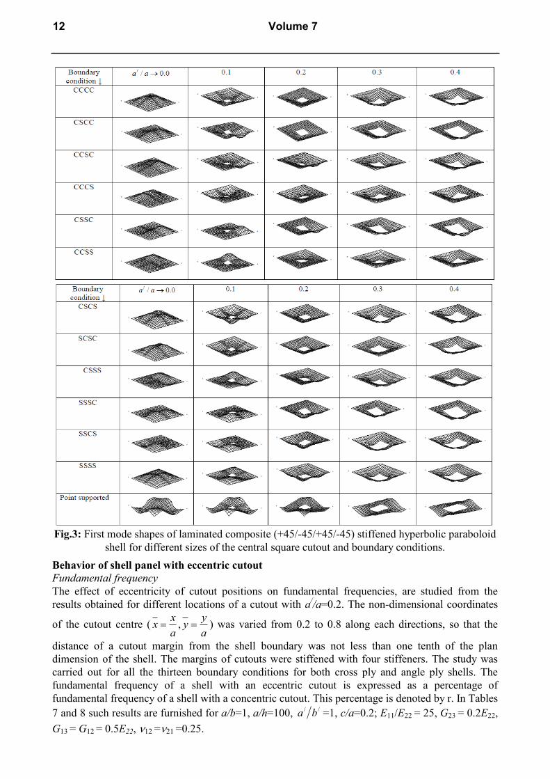
Fig.3: First mode shapes of laminated composite (+45/-45/+45/-45) stiffened hyperbolic paraboloid
shell for different sizes of the central square cutout and boundary conditions.
Behavior of shell panel with eccentric cutout
Fundamental frequency
The effect of eccentricity of cutout positions on fundamental frequencies, are studied from the
results obtained for different locations of a cutout with a//a=0.2. The non-dimensional coordinates
of the cutout centre ( ,x y
x ya a
) was varied from 0.2 to 0.8 along each directions, so that the
distance of a cutout margin from the shell boundary was not less than one tenth of the plan
dimension of the shell. The margins of cutouts were stiffened with four stiffeners. The study was
carried out for all the thirteen boundary conditions for both cross ply and angle ply shells. The
fundamental frequency of a shell with an eccentric cutout is expressed as a percentage of
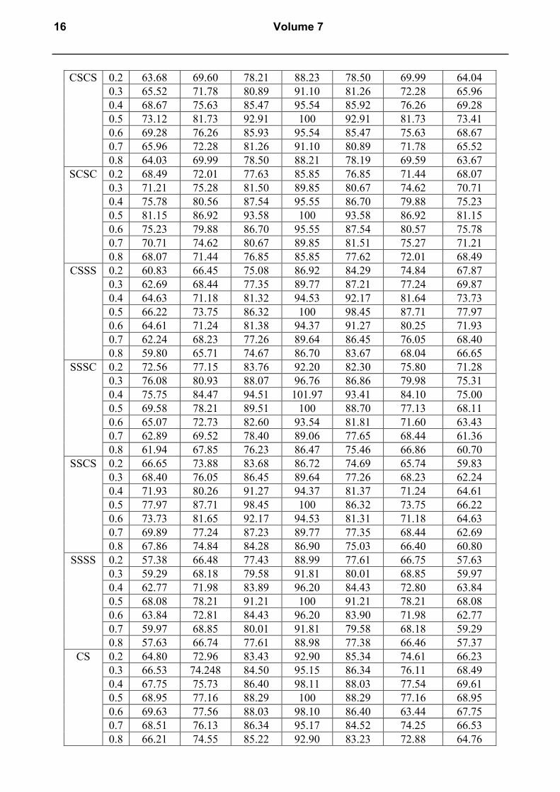
fundamental frequency of a shell with a concentric cutout. This percentage is denoted by r. In Tables
7 and 8 such results are furnished for a/b=1, a/h=100, / /a b =1, c/a=0.2; E11/E22 = 25, G23 = 0.2E22,
G13 = G12 = 0.5E22, 12 =21 =0.25.
12 Volume 7
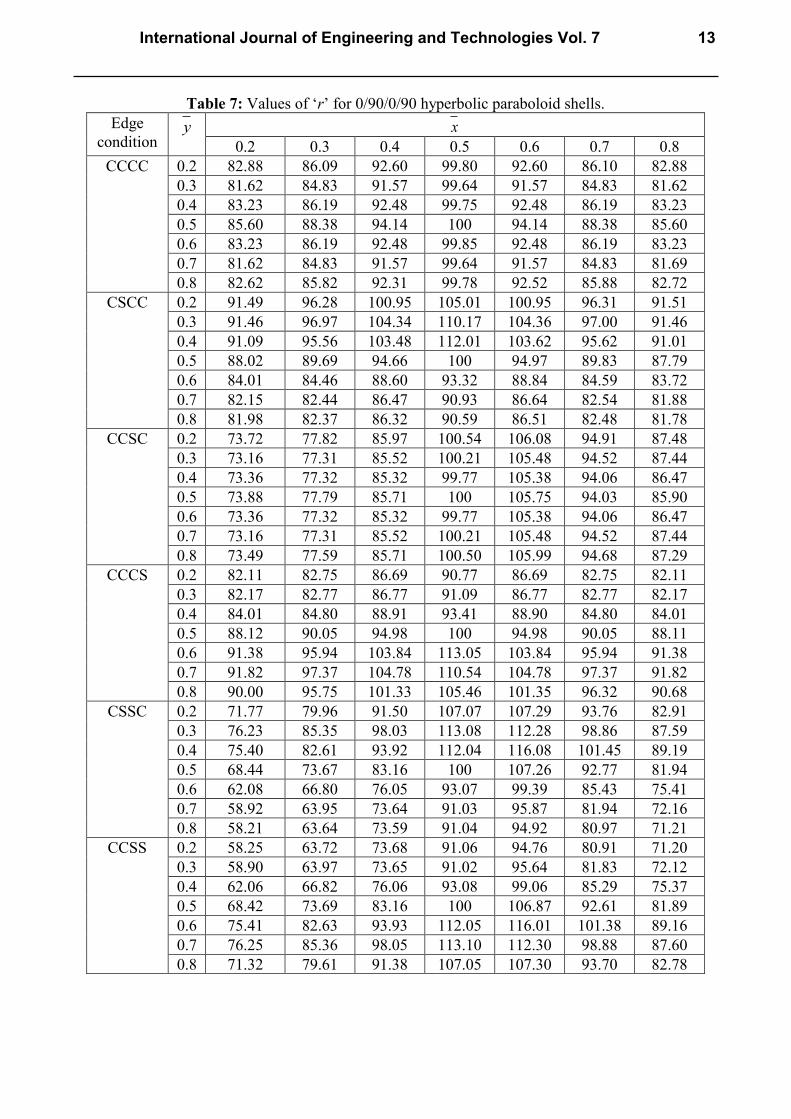
Table 7: Values of ‘r’ for 0/90/0/90 hyperbolic paraboloid shells.
Edge
condition y x
0.2 0.3 0.4 0.5 0.6 0.7 0.8
CCCC
0.2 82.88 86.09 92.60 99.80 92.60 86.10 82.88
0.3 81.62 84.83 91.57 99.64 91.57 84.83 81.62
0.4 83.23 86.19 92.48 99.75 92.48 86.19 83.23
0.5 85.60 88.38 94.14 100 94.14 88.38 85.60
0.6 83.23 86.19 92.48 99.85 92.48 86.19 83.23
0.7 81.62 84.83 91.57 99.64 91.57 84.83 81.69
0.8 82.62 85.82 92.31 99.78 92.52 85.88 82.72
CSCC
0.2 91.49 96.28 100.95 105.01 100.95 96.31 91.51
0.3 91.46 96.97 104.34 110.17 104.36 97.00 91.46
0.4 91.09 95.56 103.48 112.01 103.62 95.62 91.01
0.5 88.02 89.69 94.66 100 94.97 89.83 87.79
0.6 84.01 84.46 88.60 93.32 88.84 84.59 83.72
0.7 82.15 82.44 86.47 90.93 86.64 82.54 81.88
0.8 81.98 82.37 86.32 90.59 86.51 82.48 81.78
CCSC
0.2 73.72 77.82 85.97 100.54 106.08 94.91 87.48
0.3 73.16 77.31 85.52 100.21 105.48 94.52 87.44
0.4 73.36 77.32 85.32 99.77 105.38 94.06 86.47
0.5 73.88 77.79 85.71 100 105.75 94.03 85.90
0.6 73.36 77.32 85.32 99.77 105.38 94.06 86.47
0.7 73.16 77.31 85.52 100.21 105.48 94.52 87.44
0.8 73.49 77.59 85.71 100.50 105.99 94.68 87.29
CCCS
0.2 82.11 82.75 86.69 90.77 86.69 82.75 82.11
0.3 82.17 82.77 86.77 91.09 86.77 82.77 82.17
0.4 84.01 84.80 88.91 93.41 88.90 84.80 84.01
0.5 88.12 90.05 94.98 100 94.98 90.05 88.11
0.6 91.38 95.94 103.84 113.05 103.84 95.94 91.38
0.7 91.82 97.37 104.78 110.54 104.78 97.37 91.82
0.8 90.00 95.75 101.33 105.46 101.35 96.32 90.68
CSSC
0.2 71.77 79.96 91.50 107.07 107.29 93.76 82.91
0.3 76.23 85.35 98.03 113.08 112.28 98.86 87.59
0.4 75.40 82.61 93.92 112.04 116.08 101.45 89.19
0.5 68.44 73.67 83.16 100 107.26 92.77 81.94
0.6 62.08 66.80 76.05 93.07 99.39 85.43 75.41
0.7 58.92 63.95 73.64 91.03 95.87 81.94 72.16
0.8 58.21 63.64 73.59 91.04 94.92 80.97 71.21
CCSS
0.2 58.25 63.72 73.68 91.06 94.76 80.91 71.20
0.3 58.90 63.97 73.65 91.02 95.64 81.83 72.12
0.4 62.06 66.82 76.06 93.08 99.06 85.29 75.37
0.5 68.42 73.69 83.16 100 106.87 92.61 81.89
0.6 75.41 82.63 93.93 112.05 116.01 101.38 89.16
0.7 76.25 85.36 98.05 113.10 112.30 98.88 87.60
0.8 71.32 79.61 91.38 107.05 107.30 93.70 82.78
International Journal of Engineering and Technologies Vol. 7 13

CSCS
0.2 82.39 82.75 86.02 89.24 86.02 82.75 82.39
0.3 83.15 83.62 87.24 90.99 87.24 83.62 83.15
0.4 85.43 86.25 90.30 94.62 90.30 86.25 85.43
0.5 89.61 90.53 95.16 100 95.16 90.53 89.46
0.6 85.43 86.25 90.29 94.62 90.30 86.25 85.43
0.7 83.15 83.62 87.24 90.99 87.24 83.62 83.15
0.8 82.33 82.71 85.99 89.25 86.01 82.76 82.38
SCSC
0.2 71.41 76.93 86.16 101.86 86.16 76.93 71.41
0.3 71.56 76.94 86.05 100.83 86.04 76.94 71.56
0.4 70.99 76.53 85.67 100.01 85.67 76.53 70.99
0.5 70.69 76.48 85.81 100 85.81 76.48 70.69
0.6 70.99 76.53 85.67 100.14 85.67 76.56 70.99
0.7 71.56 76.94 86.05 100.56 86.04 76.94 71.56
0.8 71.19 76.70 85.90 100.67 86.09 76.77 71.29
CSSS
0.2 51.72 59.07 70.82 89.60 92.64 77.23 65.92
0.3 54.74 61.40 72.46 90.93 95.30 80.27 69.26
0.4 59.74 66.11 76.46 94.37 100.12 85.32 74.24
0.5 65.28 73.99 82.80 100 107.08 91.45 79.13
0.6 59.74 66.11 76.46 94.37 100.12 85.32 74.24
0.7 54.74 61.40 72.46 90.93 95.30 80.26 69.26
0.8 51.71 59.06 70.79 89.58 92.61 77.22 65.90
SSSC
0.2 68.33 77.85 90.13 102.99 90.13 77.85 68.33
0.3 72.36 82.73 96.11 107.63 96.11 82.73 72.36
0.4 69.89 78.93 91.63 109.01 91.63 78.92 69.89
0.5 62.18 69.81 80.99 100 80.99 69.81 62.18
0.6 56.27 63.36 74.19 90.79 74.2 63.36 56.27
0.7 53.77 60.90 71.95 88.98 71.95 60.90 53.77
0.8 53.46 60.75 71.94 89.13 71.98 60.77 53.50
SSCS
0.2 65.92 77.23 92.64 89.60 70.82 59.07 51.72
0.3 69.26 80.26 95.30 90.93 72.46 61.40 54.74
0.4 74.24 85.32 100.12 94.37 76.46 66.11 59.74
0.5 79.13 91.45 107.08 100 82.80 73.99 65.28
0.6 74.24 85.32 100.12 94.37 76.46 66.11 59.74
0.7 69.25 80.26 95.30 90.93 72.46 61.40 54.73
0.8 65.90 77.22 92.63 89.58 70.79 59.05 51.70
SSSS
0.2 48.35 58.19 71.73 90.91 71.73 58.19 48.35
0.3 51.21 60.39 73.30 92.10 73.30 60.39 51.21
0.4 56.14 64.92 77.21 95.34 77.21 64.91 56.14
0.5 62.58 72.14 83.37 100 83.37 72.14 62.57
0.6 56.14 64.91 77.21 95.33 77.21 64.91 56.14
0.7 51.21 60.38 73.30 92.10 73.30 60.39 51.21
0.8 48.34 58.18 71.69 92.03 71.71 58.16 48.34
CS 0.2 87.88 97.94 104.11 107.44 104.11 97.94 87.88
0.3 88.96 95.74 101.44 104.94 101.42 95.74 88.94
0.4 90.09 93.54 98.07 101.64 98.07 93.51 90.09
0.5 90.55 92.51 96.53 100 96.52 92.51 90.53
0.6 90.09 93.54 98.09 101.64 98.07 93.54 90.09
0.7 88.94 95.74 101.42 104.94 101.42 95.74 88.94
0.8 87.81 97.72 103.79 107.37 103.84 97.72 87.83
14 Volume 7
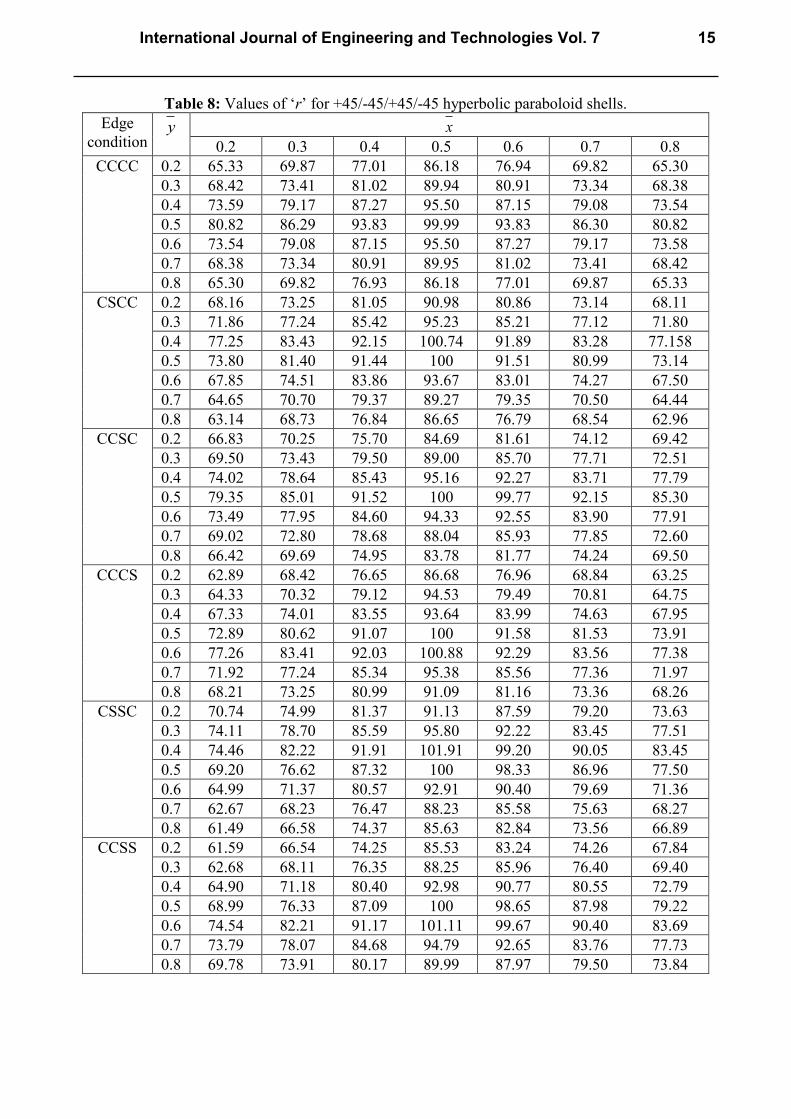
Table 8: Values of ‘r’ for +45/-45/+45/-45 hyperbolic paraboloid shells.
Edge
condition y x
0.2 0.3 0.4 0.5 0.6 0.7 0.8
CCCC 0.2 65.33 69.87 77.01 86.18 76.94 69.82 65.30
0.3 68.42 73.41 81.02 89.94 80.91 73.34 68.38
0.4 73.59 79.17 87.27 95.50 87.15 79.08 73.54
0.5 80.82 86.29 93.83 99.99 93.83 86.30 80.82
0.6 73.54 79.08 87.15 95.50 87.27 79.17 73.58
0.7 68.38 73.34 80.91 89.95 81.02 73.41 68.42
0.8 65.30 69.82 76.93 86.18 77.01 69.87 65.33
CSCC 0.2 68.16 73.25 81.05 90.98 80.86 73.14 68.11
0.3 71.86 77.24 85.42 95.23 85.21 77.12 71.80
0.4 77.25 83.43 92.15 100.74 91.89 83.28 77.158
0.5 73.80 81.40 91.44 100 91.51 80.99 73.14
0.6 67.85 74.51 83.86 93.67 83.01 74.27 67.50
0.7 64.65 70.70 79.37 89.27 79.35 70.50 64.44
0.8 63.14 68.73 76.84 86.65 76.79 68.54 62.96
CCSC 0.2 66.83 70.25 75.70 84.69 81.61 74.12 69.42
0.3 69.50 73.43 79.50 89.00 85.70 77.71 72.51
0.4 74.02 78.64 85.43 95.16 92.27 83.71 77.79
0.5 79.35 85.01 91.52 100 99.77 92.15 85.30
0.6 73.49 77.95 84.60 94.33 92.55 83.90 77.91
0.7 69.02 72.80 78.68 88.04 85.93 77.85 72.60
0.8 66.42 69.69 74.95 83.78 81.77 74.24 69.50
CCCS 0.2 62.89 68.42 76.65 86.68 76.96 68.84 63.25
0.3 64.33 70.32 79.12 94.53 79.49 70.81 64.75
0.4 67.33 74.01 83.55 93.64 83.99 74.63 67.95
0.5 72.89 80.62 91.07 100 91.58 81.53 73.91
0.6 77.26 83.41 92.03 100.88 92.29 83.56 77.38
0.7 71.92 77.24 85.34 95.38 85.56 77.36 71.97
0.8 68.21 73.25 80.99 91.09 81.16 73.36 68.26
CSSC 0.2 70.74 74.99 81.37 91.13 87.59 79.20 73.63
0.3 74.11 78.70 85.59 95.80 92.22 83.45 77.51
0.4 74.46 82.22 91.91 101.91 99.20 90.05 83.45
0.5 69.20 76.62 87.32 100 98.33 86.96 77.50
0.6 64.99 71.37 80.57 92.91 90.40 79.69 71.36
0.7 62.67 68.23 76.47 88.23 85.58 75.63 68.27
0.8 61.49 66.58 74.37 85.63 82.84 73.56 66.89
CCSS 0.2 61.59 66.54 74.25 85.53 83.24 74.26 67.84
0.3 62.68 68.11 76.35 88.25 85.96 76.40 69.40
0.4 64.90 71.18 80.40 92.98 90.77 80.55 72.79
0.5 68.99 76.33 87.09 100 98.65 87.98 79.22
0.6 74.54 82.21 91.17 101.11 99.67 90.40 83.69
0.7 73.79 78.07 84.68 94.79 92.65 83.76 77.73
0.8 69.78 73.91 80.17 89.99 87.97 79.50 73.84
International Journal of Engineering and Technologies Vol. 7 15
CSCS 0.2 63.68 69.60 78.21 88.23 78.50 69.99 64.04
0.3 65.52 71.78 80.89 91.10 81.26 72.28 65.96
0.4 68.67 75.63 85.47 95.54 85.92 76.26 69.28
0.5 73.12 81.73 92.91 100 92.91 81.73 73.41
0.6 69.28 76.26 85.93 95.54 85.47 75.63 68.67
0.7 65.96 72.28 81.26 91.10 80.89 71.78 65.52
0.8 64.03 69.99 78.50 88.21 78.19 69.59 63.67
SCSC 0.2 68.49 72.01 77.63 85.85 76.85 71.44 68.07
0.3 71.21 75.28 81.50 89.85 80.67 74.62 70.71
0.4 75.78 80.56 87.54 95.55 86.70 79.88 75.23
0.5 81.15 86.92 93.58 100 93.58 86.92 81.15
0.6 75.23 79.88 86.70 95.55 87.54 80.57 75.78
0.7 70.71 74.62 80.67 89.85 81.51 75.27 71.21
0.8 68.07 71.44 76.85 85.85 77.62 72.01 68.49
CSSS 0.2 60.83 66.45 75.08 86.92 84.29 74.84 67.87
0.3 62.69 68.44 77.35 89.77 87.21 77.24 69.87
0.4 64.63 71.18 81.32 94.53 92.17 81.64 73.73
0.5 66.22 73.75 86.32 100 98.45 87.71 77.97
0.6 64.61 71.24 81.38 94.37 91.27 80.25 71.93
0.7 62.24 68.23 77.26 89.64 86.45 76.05 68.40
0.8 59.80 65.71 74.67 86.70 83.67 68.04 66.65
SSSC 0.2 72.56 77.15 83.76 92.20 82.30 75.80 71.28
0.3 76.08 80.93 88.07 96.76 86.86 79.98 75.31
0.4 75.75 84.47 94.51 101.97 93.41 84.10 75.00
0.5 69.58 78.21 89.51 100 88.70 77.13 68.11
0.6 65.07 72.73 82.60 93.54 81.81 71.60 63.43
0.7 62.89 69.52 78.40 89.06 77.65 68.44 61.36
0.8 61.94 67.85 76.23 86.47 75.46 66.86 60.70
SSCS 0.2 66.65 73.88 83.68 86.72 74.69 65.74 59.83
0.3 68.40 76.05 86.45 89.64 77.26 68.23 62.24
0.4 71.93 80.26 91.27 94.37 81.37 71.24 64.61
0.5 77.97 87.71 98.45 100 86.32 73.75 66.22
0.6 73.73 81.65 92.17 94.53 81.31 71.18 64.63
0.7 69.89 77.24 87.23 89.77 77.35 68.44 62.69
0.8 67.86 74.84 84.28 86.90 75.03 66.40 60.80
SSSS 0.2 57.38 66.48 77.43 88.99 77.61 66.75 57.63
0.3 59.29 68.18 79.58 91.81 80.01 68.85 59.97
0.4 62.77 71.98 83.89 96.20 84.43 72.80 63.84
0.5 68.08 78.21 91.21 100 91.21 78.21 68.08
0.6 63.84 72.81 84.43 96.20 83.90 71.98 62.77
0.7 59.97 68.85 80.01 91.81 79.58 68.18 59.29
0.8 57.63 66.74 77.61 88.98 77.38 66.46 57.37
CS 0.2 64.80 72.96 83.43 92.90 85.34 74.61 66.23
0.3 66.53 74.248 84.50 95.15 86.34 76.11 68.49
0.4 67.75 75.73 86.40 98.11 88.03 77.54 69.61
0.5 68.95 77.16 88.29 100 88.29 77.16 68.95
0.6 69.63 77.56 88.03 98.10 86.40 63.44 67.75
0.7 68.51 76.13 86.34 95.17 84.52 74.25 66.53
0.8 66.21 74.55 85.22 92.90 83.23 72.88 64.76
16 Volume 7

Table 9: Maximum values of r with corresponding coordinates of cutout centres and zones where
r≥90 and r≥95 for 0/90/0/90 hyperbolic paraboloid shells
Boundary
Condition
Maximum
values of r
Co-ordinate of
cutout centre
Area in which the value
of r≥90
Area in which
the value r≥95
CCCC
100.00 (0.5,0.5) x =0.4, 0.6
0.2≤ y ≤0.8
x =0.5
0.2 ≤ y ≤0.8
CSCC
105.01 (0.5,0.2) x =0.2,0.8
0.2 ≤ y ≤0.4;
x =0.5, 0.5≤ y ≤0.8
0.3≤ x ≤0.7
0.2≤ y ≤0.4
CCSC
106.08 (0.6,0.2) x =0.7, 0.2 ≤ y ≤0.8 0.5≤ x ≤0.6
0.2≤ y ≤0.8
CCCS
113.05 (0.5,0.6) x =0.2,0.8, 0.6 ≤ y ≤0.8;
0.3≤ x ≤0.7, y =0.5
0.3≤ x ≤0.7
0.6 ≤ y ≤0.8
CSSC
116.08 (0.6,0.4)
Nil
0.5≤ x ≤0.6
0.2 ≤ y ≤0.5
CCSS
116.01
(0.6,0.6)
Nil
0.5≤ x ≤0.6
0.5 ≤ y ≤0.8
CSCS
100.00 (0.5,0.5) 0.4≤ x ≤0.6, 0.4 ≤ y ≤0.6 0.4≤ x ≤0.6
y =0.5
SCSC
101.86 (0.5,0.2)
Nil
x =0.5
0.2≤ y ≤0.8
CSSS
107.08 (0.6,0.5) x =0.5
0.3 ≤ y ≤0.7
x =0.6
0.3 ≤ y ≤0.7
SSSC
109.01 (0.5,0.4) x =0.4, 0.6
0.2 ≤ y ≤0.4
x =0.5
0.2 ≤ y ≤0.5
SSCS
107.08 (0.4,0.5) x =0.5
0.3 ≤ y ≤0.7
x =0.4
0.3 ≤ y ≤0.7
SSSS
100.00 (0.5,0.5) x =0.5,0.2 ≤ y ≤0.8 x =0.5, y =0.5
CS 107.37 (0.5,0.8) The whole area except
corner points.
0.4≤ x ≤0.6
0.2 ≤ y ≤0.8
a/b=1, a/h=100, / /a b =1, c/a=0.2; E11/E22 = 25, G23 = 0.2E22, G13 = G12 = 0.5E22,12 =21 =0.25.
It can be seen that eccentricity of the cutout along the length of the shell towards the
clamped edges makes it more flexible. It is also seen that almost all the cases r value is maximum in
and around 0.5x and 0.5y . When edge, opposite to a clamped edge is simply supported, r
value first increases towards the simply supported edge then decreases. But, when two opposite
edges are simply supported r value decreases towards the simply supported edges. Again in case of
an angle ply shell, if the simply supported edge be the hyperbolic one then r value decreases towards
the edge. So, for functional purposes, if a shift of central cutout is required, eccentricity of a cutout
along the length or width should preferably be towards the simply supported edge which is opposite
International Journal of Engineering and Technologies Vol. 7 17
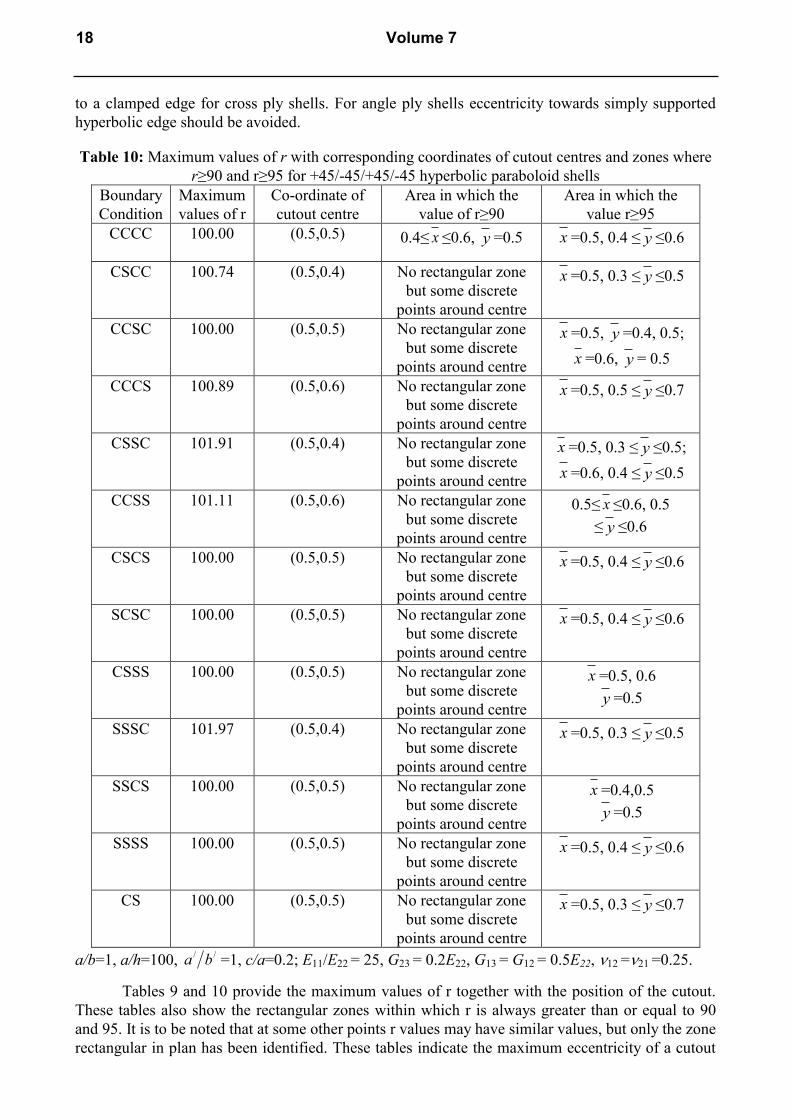
to a clamped edge for cross ply shells. For angle ply shells eccentricity towards simply supported
hyperbolic edge should be avoided.
Table 10: Maximum values of r with corresponding coordinates of cutout centres and zones where
r≥90 and r≥95 for +45/-45/+45/-45 hyperbolic paraboloid shells
Boundary
Condition
Maximum
values of r
Co-ordinate of
cutout centre
Area in which the
value of r≥90
Area in which the
value r≥95
CCCC
100.00 (0.5,0.5) 0.4≤ x ≤0.6, y =0.5 x =0.5, 0.4 ≤ y ≤0.6
CSCC 100.74 (0.5,0.4) No rectangular zone
but some discrete
points around centre
x =0.5, 0.3 ≤ y ≤0.5
CCSC
100.00 (0.5,0.5) No rectangular zone
but some discrete
points around centre
x =0.5, y =0.4, 0.5;
x =0.6, y = 0.5
CCCS
100.89 (0.5,0.6) No rectangular zone
but some discrete
points around centre
x =0.5, 0.5 ≤ y ≤0.7
CSSC
101.91 (0.5,0.4) No rectangular zone
but some discrete
points around centre
x =0.5, 0.3 ≤ y ≤0.5;
x =0.6, 0.4 ≤ y ≤0.5
CCSS
101.11 (0.5,0.6) No rectangular zone
but some discrete
points around centre
0.5≤ x ≤0.6, 0.5
≤ y ≤0.6
CSCS
100.00 (0.5,0.5) No rectangular zone
but some discrete
points around centre
x =0.5, 0.4 ≤ y ≤0.6
SCSC
100.00 (0.5,0.5) No rectangular zone
but some discrete
points around centre
x =0.5, 0.4 ≤ y ≤0.6
CSSS
100.00 (0.5,0.5) No rectangular zone
but some discrete
points around centre
x =0.5, 0.6
y =0.5
SSSC
101.97 (0.5,0.4) No rectangular zone
but some discrete
points around centre
x =0.5, 0.3 ≤ y ≤0.5
SSCS
100.00 (0.5,0.5) No rectangular zone
but some discrete
points around centre
x =0.4,0.5
y =0.5
SSSS
100.00 (0.5,0.5) No rectangular zone
but some discrete
points around centre
x =0.5, 0.4 ≤ y ≤0.6
CS
100.00 (0.5,0.5) No rectangular zone
but some discrete
points around centre
x =0.5, 0.3 ≤ y ≤0.7
a/b=1, a/h=100, / /a b =1, c/a=0.2; E11/E22 = 25, G23 = 0.2E22, G13 = G12 = 0.5E22, 12 =21 =0.25.
Tables 9 and 10 provide the maximum values of r together with the position of the cutout.
These tables also show the rectangular zones within which r is always greater than or equal to 90
and 95. It is to be noted that at some other points r values may have similar values, but only the zone
rectangular in plan has been identified. These tables indicate the maximum eccentricity of a cutout
18 Volume 7
which can be permitted if the fundamental frequency of a concentrically punctured shell is not to
reduce a drastic amount. So these tables will help practicing engineers.
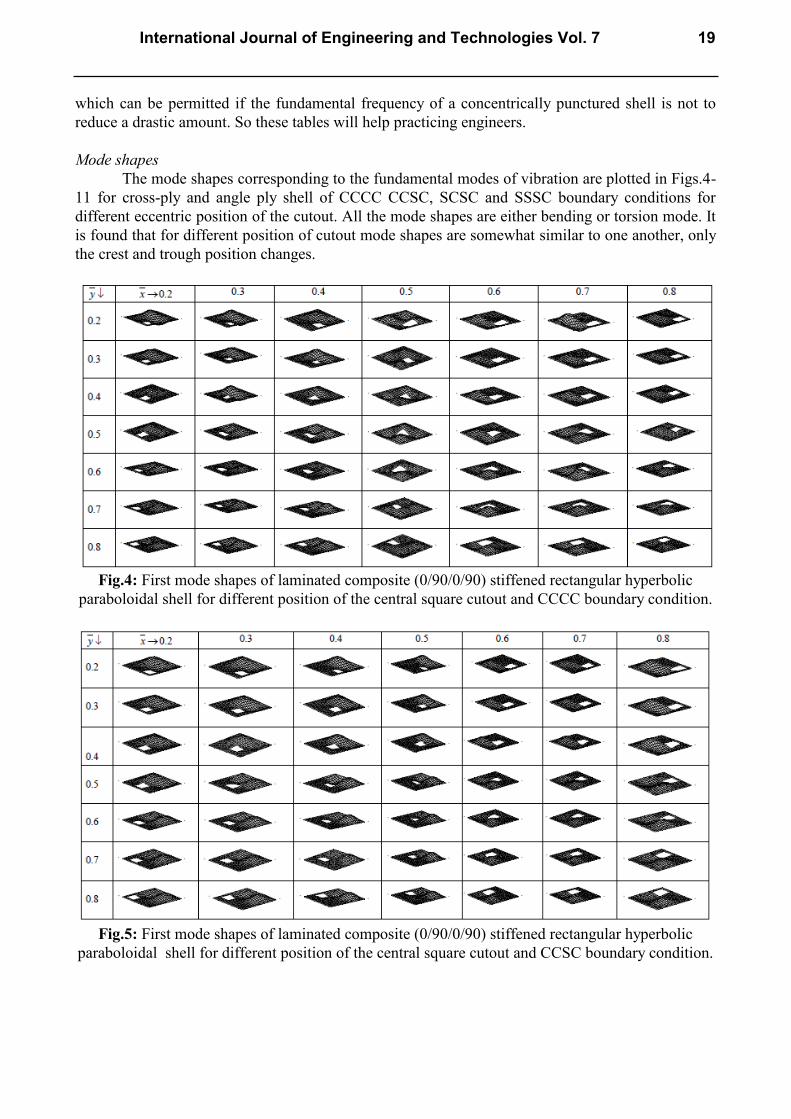
Mode shapes
The mode shapes corresponding to the fundamental modes of vibration are plotted in Figs.4-
11 for cross-ply and angle ply shell of CCCC CCSC, SCSC and SSSC boundary conditions for
different eccentric position of the cutout. All the mode shapes are either bending or torsion mode. It
is found that for different position of cutout mode shapes are somewhat similar to one another, only
the crest and trough position changes.
Fig.4: First mode shapes of laminated composite (0/90/0/90) stiffened rectangular hyperbolic
paraboloidal shell for different position of the central square cutout and CCCC boundary condition.
Fig.5: First mode shapes of laminated composite (0/90/0/90) stiffened rectangular hyperbolic
paraboloidal shell for different position of the central square cutout and CCSC boundary condition.
International Journal of Engineering and Technologies Vol. 7 19
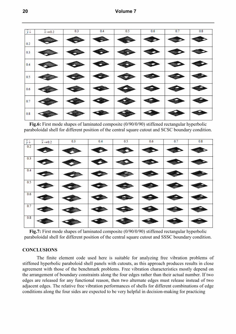
Fig.6: First mode shapes of laminated composite (0/90/0/90) stiffened rectangular hyperbolic
paraboloidal shell for different position of the central square cutout and SCSC boundary condition.
Fig.7: First mode shapes of laminated composite (0/90/0/90) stiffened rectangular hyperbolic
paraboloidal shell for different position of the central square cutout and SSSC boundary condition.
CONCLUSIONS
The finite element code used here is suitable for analyzing free vibration problems of
stiffened hyperbolic paraboloid shell panels with cutouts, as this approach produces results in close
agreement with those of the benchmark problems. Free vibration characteristics mostly depend on
the arrangement of boundary constraints along the four edges rather than their actual number. If two
edges are released for any functional reason, then two alternate edges must release instead of two
adjacent edges. The relative free vibration performances of shells for different combinations of edge
conditions along the four sides are expected to be very helpful in decision-making for practicing
20 Volume 7

Fig.8: First mode shapes of laminated composite (+45/-45/+45/-45) stiffened rectangular hyperbolic
paraboloidal shell for different position of the central square cutout and CCCC boundary condition.
Fig.9: First mode shapes of laminated composite (+45/-45/+45/-45) stiffened rectangular hyperbolic
paraboloidal shell for different position of the central square cutout and CCSC boundary condition.
engineers. For functional purposes, if a shift of central cutout is required, eccentricity of a cutout
along the length or width should preferably be towards the simply supported edge which is opposite
to a clamped edge for cross ply shells. For angle ply shells eccentricity towards simply supported
hyperbolic edge should be avoided. The information regarding the behaviour of stiffened hyperbolic
paraboloid shell with eccentric cutouts for a wide spectrum of eccentricity and boundary conditions
for cross ply and angle ply shells may also be used as design aids for structural engineers. The
present study provides the specific zones within which the cutout centre may be moved so that the
loss of frequency is less than 5% and 10% with respect to a shell with a central cutout. That will
help an engineer to make a decision regarding the eccentricity of the cutout centre that can be
allowed.
International Journal of Engineering and Technologies Vol. 7 21
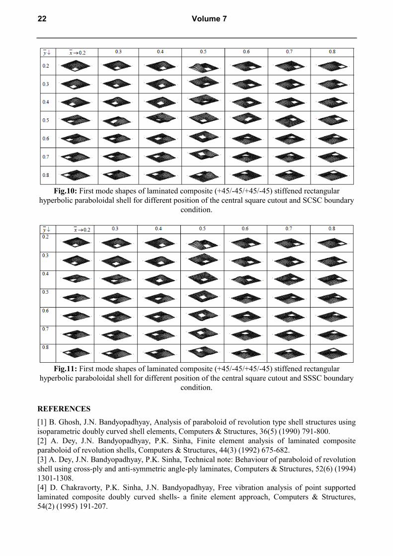
Fig.10: First mode shapes of laminated composite (+45/-45/+45/-45) stiffened rectangular
hyperbolic paraboloidal shell for different position of the central square cutout and SCSC boundary
condition.
Fig.11: First mode shapes of laminated composite (+45/-45/+45/-45) stiffened rectangular
hyperbolic paraboloidal shell for different position of the central square cutout and SSSC boundary
condition.
REFERENCES
[1] B. Ghosh, J.N. Bandyopadhyay, Analysis of paraboloid of revolution type shell structures using
isoparametric doubly curved shell elements, Computers & Structures, 36(5) (1990) 791-800.
[2] A. Dey, J.N. Bandyopadhyay, P.K. Sinha, Finite element analysis of laminated composite
paraboloid of revolution shells, Computers & Structures, 44(3) (1992) 675-682.
[3] A. Dey, J.N. Bandyopadhyay, P.K. Sinha, Technical note: Behaviour of paraboloid of revolution
shell using cross-ply and anti-symmetric angle-ply laminates, Computers & Structures, 52(6) (1994)
1301-1308.
[4] D. Chakravorty, P.K. Sinha, J.N. Bandyopadhyay, Free vibration analysis of point supported
laminated composite doubly curved shells- a finite element approach, Computers & Structures,
54(2) (1995) 191-207.
22 Volume 7
[5] D. Chakravorty, P.K. Sinha, J.N. Bandyopadhyay, Finite element free vibration analysis of
doubly curved laminated composite shells, J. Sound and Vibration, 191(4) (1996) 491-504.
[6] A.N. Nayak, J.N. Bandyopadhyay, Free vibration analysis and design aids of stiffened conoidal
shells. Journal of Engineering Mechanics, 128 (2002) 419-427.
[7] A.N. Nayak, J.N. Bandyopadhyay, Free vibration analysis of laminated stiffened shells. Journal
of Engineering Mechanics, 131 (2005) 100-105.
[8] A.N. Nayak, J.N. Bandyopadhyay, Dynamic response analysis of stiffened conoidal shells,
Journal of Sound and Vibration, 291 (2006) 1288-1297.
[9] H.S. Das, D. Chakravorty, Design aids and selection guidelines for composite conoidal shell
roofs-a finite element application, Journal of Reinforced Plastic and Composites, 26 (2007) 1793-
1819.
[10] H.S. Das, D. Chakravorty, Natural frequencies and mode shapes of composite conoids with
complicated boundary conditions, Journal of Reinforced Plastic and Composites, 27 (2008) 1397-
1415.
[11] H.S. Das, D. Chakravorty, Finite element application in analysis and design of point supported
composite conoidal shell roofs suggesting selection guidelines, Journal of Strain Analysis in
Engineering Design., 45(3) (2010) 165-177.
[12] H.S. Das, D. Chakravorty, Bending analysis of stiffened composite conoidal shell roofs through
finite element application. Journal of Composite Materials, 45 (2011) 525-542.
[13] S. Pradyumna, J.N. Bandyopadhyay, Static and free vibration analyses of laminated shells
using a higher order theory. Journal of Reinforced Plastics and Composites, 27 (2008) 167-186.
[14] S. Pradyumna, J.N. Bandyopadhyay, Dynamic instability behaviour of laminated hypar and
conoid shells using a higher-order shear deformation theory, Thin Walled Structures, 49 (2011) 77-
84.
[15] J.N. Reddy, Large amplitude flexural vibration of layered composite plates with cutouts,
Journal of Sound and Vibration, 83(1) (1982) 1-10.
[16] S.K. Malhotra, N. Ganesan, M.A. Veluswami, Vibration of composite plate with cutouts,
Journal of Aeronautical Society of India, 41 (1989) 61-64.
[17] B. Sivasubramanian, A.M. Kulkarni, G.V. Rao, A. Krishnan, Free vibration of curved panels
with cutouts, Journal of Sound and Vibration, 200(2) (1997) 227-234.
[18] K. Sivakumar, N.G.R. Iyengar, K. Deb, Free vibration of laminated composite plates with
cutout, Journal of sound and Vibration, 221(3) (1999) 443-465.
[19] R.E. Rossi, Transverse vibrations of thin, orthotropic rectangular plates with rectangular
cutouts with fixed boundaries, Journal of Sound and Vibration, 221(4) (1999) 733-736.
[20] M. Huang, T. Sakiyama, Free vibration analysis of rectangular plates with variously-shaped
holes, Journal of Sound and Vibration, 226(4) (1999) 769-786.
[21] S.S. Hota, P. Padhi, Vibration of plates with arbitrary shapes of cutouts, Journal of Sound and
Vibration, 302(4-5) (2007) 1030-1036.
[22] D. Chakravorty, P.K. Sinha, J.N. Bandyopadhyay, Applications of FEM on free and forced
vibration of laminated shells, Journal of Engineering Mechanics; 124(1) (1998) 1-8.
[23] B. Sivasubramonian, G.V. Rao, A. Krishnan, Free vibration of longitudinally stiffened curved
panels with cutout, Journal of Sound and Vibration, 226(1) (1999) 41-55.
[24] S.S. Hota, D. Chakravorty, Free vibration of stiffened conoidal shell roofs with cutouts, Journal
of Vibration and Control, 13(3) (2007) 221-240.
[25] N. Nanda, J.N. Bandyopadhyay, Nonlinear free vibration analysis of laminated composite
cylindrical shells with cutouts, Journal of Reinforced Plastic and Composites, 26(14) (2007) 143-
1427.
[26] A. Kumar, A. Chakrabarti, P. Bhargava, Vibration of composite cylindrical shells with cutouts
using higher order theory, International Journal of Scientific and Industrial Research, 5(4) (2013)
199-202.
International Journal of Engineering and Technologies Vol. 7 23

[27] V.V. Vasiliev, R.M. Jones, L.L. Man, Mechanics of Composite Structures, Taylor and Francis,
USA, (1993).
[28] M S. Qatu, Vibration of Laminated Shells and Plates, Elsevier, UK, (2004).
[29] S. Sahoo, D. Chakravorty, Finite element bending behaviour of composite hyperbolic
paraboloid shells with various edge conditions, Journal of Strain Analysis for Engineering Design,
39(5) (2004) 499-513.
[31] A. Mukherjee, M. Mukhopadhyay, Finite element free vibration of eccentrically stiffened
plates, Computers and Structures, 30 (1998) 1303-1317.
[32] A.N. Nayak, J.N. Bandyopadhyay, On the free vibration of stiffened shallow shells, Journal of
Sound and Vibration, 255(2) (2002) 357-382.
24 Volume 7