Embed Size (px)
Citation preview
Int. J. Exergy, Vol. 4, No. 4, 2007 401
Copyright © 2007 Inderscience Enterprises Ltd.
Performance evaluation of heat transfer enhancement for internal flow based on exergy analysis
S.A. Abdel-Moneim and R.K. Ali* Faculty of Engineering (Shoubra), Mechanical Engineering Department, Benha University, 108 Shoubra St. Cairo, Egypt E-mail: [email protected] E-mail: [email protected] *Corresponding author
Abstract: A performance evaluation based on exergy analysis was proposed to evaluate the benefits of different enhancement techniques for flow inside tubes. The present performance evaluation was developed based on the application of the principle of entropy generation. A semi-analytical model was developed to predict the entropy generation and the exergy destruction rates associated with both flow friction and heat transfer. This model was based on measurements and empirical correlations for both flow and heat transfer characteristics. The present performance evaluation was applied on flow through tubes enhanced with twisted-tapes inserts, spirally internal fins and conical turbulators for three different fluids. It was found that using specific types of enhancement techniques reduces the irreversibility owing to heat transfer across a finite temperature difference and in the same time increases that part of irreversibility resulting from the flow friction. Therefore, a thermodynamic optimum at a minimum exergy destruction rate can be achieved for different enhancement techniques and different flow conditions.
Keywords: heat transfer enhancement; exergy; turbulators; twisted tape inserts; internally finned tubes.
Reference to this paper should be made as follows: Abdel-Moneim, S.A. and Ali, R.K. (2007) ‘Performance evaluation of heat transfer enhancement for internal flow based on exergy analysis’, Int. J. Exergy, Vol. 4, No. 4, pp.401–420.
Biographical notes: S.A. Abdel-Moneium obtained his BSc in Mechanical Engineering in 1984 from Zagazig University in Egypt and his MSc and PhD Degrees from Cairo University in 1988 and 1994. He currently works as a Professor in Benha University. His major interests are heat transfer and thermodynamic analysis.
R.K. Ali received his BSc and MSc from University of Zagazig in Mechanical Engineering in 1994 and 1999. He received his PhD from the University of Zagazig in Power Mechanical Engineering in 2004. He currently works as a Lecturer in the Benha University, His research interests lie in the fields of alternative sources of energy, advanced methods of thermodynamic analysis and heat transfer.
402 S.A. Abdel-Moneim and R.K. Ali
1 Introduction
Exergy destruction owing to entropy generation is accompanied with any heat transfer process in general. This entropy generation is owing to the irreversible nature of heat transfer down temperature gradients and the viscous flow friction. Therefore, to modify and optimise energy conversion systems it is essential to understand how entropy is being generated in convective heat transfer processes. Various types of heat transfer enhancement techniques have been developed and tested in different ways. Webb (1981, 1994) and Abdel-Moneim and El-Shamy (2000) have used the efficiency index (Stanton number ratio to Fanning friction factor ratio) as a Performance Evaluation Criterion (PEC) to evaluate the performance of various augmentation techniques. These criteria do not take into consideration the thermodynamic impact of heat transfer augmentation techniques. Durmus (2004) studied the effect of inserted turbulators on flow and heat transfer characteristics for isothermally heated tube from the outer surface. Marner and Bergles (1989) tested the effect of inserted twisted tape and internal fins on flow and heat transfer characteristics with the outer surface of the tube is subjected to isothermal heating. Sahin (1988) developed a theoretical model based on the exergy concept to predict the entropy generation for a fully developed laminar flow in a duct subjected to a constant wall temperature. It is found that the entropy generation increases along the duct length. Bejan (1980, 1982) and co-worker proposed a PEC based on the 2nd law of thermodynamics. The irreversibility and entropy generation rates associated with the augmentation devices are used as a PEC. In this sense, the effective technique is that one leads to a reduction in the entropy generation rate and in accordance reduces the exergy destruction rate. In addition, the entropy generation number following Bejan (1982) is an important parameter in deciding the true merit of a heat transfer augmentation technique. Prasad and Shen (1993, 1994) applied a PEC, based on the exergy analysis on a tubular heat exchanger with wire-coil inserts. In this analysis the net exergy destruction associated with heat transfer across a finite temperature difference and from the flow friction was used as an evaluation criterion. Also, a thermodynamic optimum was obtained by minimising the net exergy destruction rate. Abdel-Moneium (2002) applied PEC, based on exergy analysis to the enhanced internal flow with wire-coils and twisted-tape inserts. Also, Wang and Sunden (2002) introduced performance comparison for flow inside tubes with twisted-tape and wire-coils inserts. Nag and Mukherjee (1987) and Zimparov (2000) modified Bejan’s entropy generation method by including the effect of the variation in the fluid temperature along a heat transfer duct with constant wall temperature. Zimparov (2000) applied this modified PEC to ten spirally corrugated tubes to assess the benefits of these tubes. It was found that a rib-height-to diameter ratio of about 0.04 is an optimum for this type of tubes. In the present study an evaluation method based on exergy analysis is proposed using the principles of the first and second laws of thermodynamics. The proposed evaluation technique has applied on variety of heat transfer enhancement techniques for both laminar and turbulent internal flow regimes. The numerical study is used to evaluate the effect of internal fins and twisted-tape inserts used by Marner and Bergles (1989) and conical turbulators used by Durmus (2004) based on exergy analysis. The present investigation aims to provide heat transfer equipment designers with knowledge for the thermodynamic impact owing to entropy generation and exergy destruction associated with the use of the different enhanced surfaces.
Performance evaluation of heat transfer enhancement 403
2 Modelling
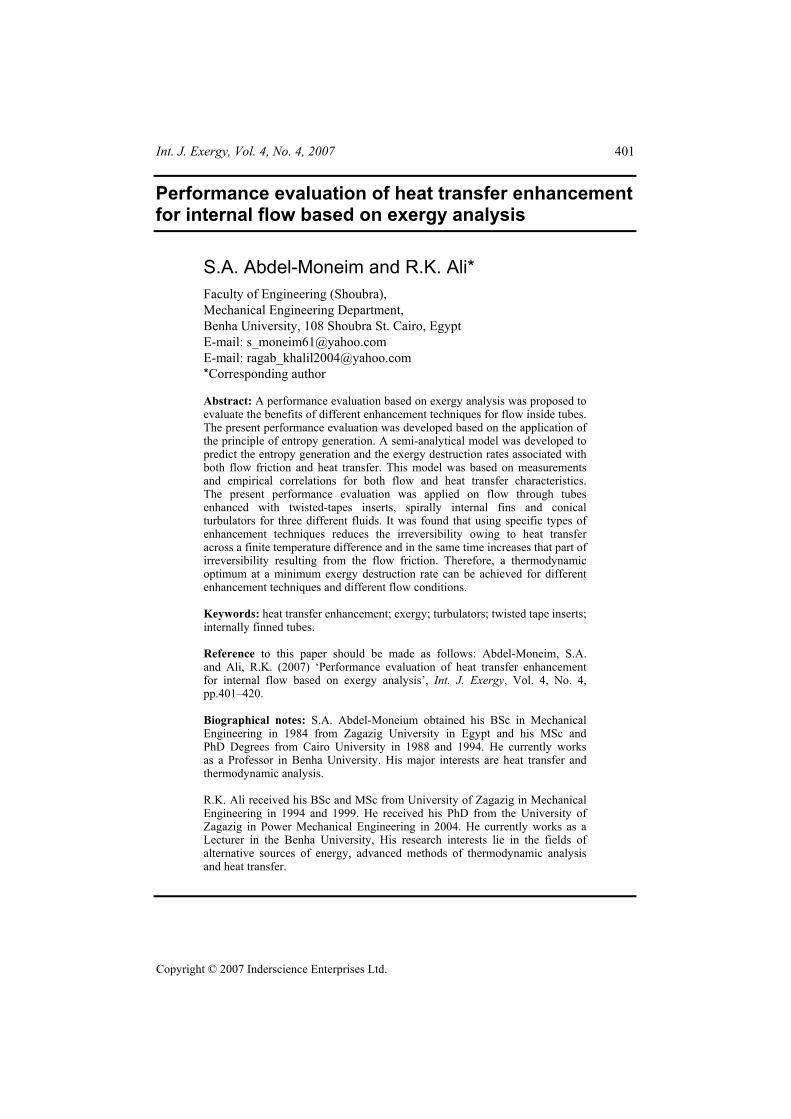
Considering a control volume of a length dx for a flow with heat transfer through a duct with arbitrary cross section and subjected to a uniform heat flux as shown in Figure 1(a), the energy balance is,
dpQ mc Tδ = (1)
and the heat transfer equation is,
( d ) d .Q q w x h Tw xδ ′′= = ∆ (2)
Equations (1) and (2) can be simply combined to give the flow bulk temperature distribution in the differential form as:
d d .p
hw TT xmc
∆= (3)
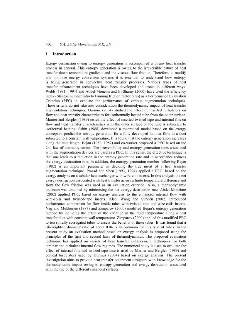
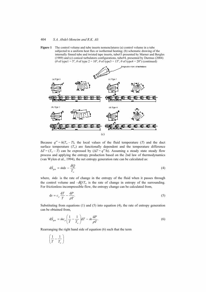
Figure 1 The control volume and tube inserts nomenclatures: (a) control volume in a tube subjected to a uniform heat flux or isothermal heating; (b) schematic drawing of the internally finned tube and twisted tape inserts, tube#3 presented by Marner and Bergles (1989) and (c) conical turbulators configurations, tube#4, presented by Durmus (2004) (θ of type1 = 5o, θ of type 2 = 10o, θ of type3 = 15o, θ of type4 = 20o)
(a)
(b)
404 S.A. Abdel-Moneim and R.K. Ali
Figure 1 The control volume and tube inserts nomenclatures (a) control volume in a tube subjected to a uniform heat flux or isothermal heating; (b) schematic drawing of the internally finned tube and twisted tape inserts, tube#3 presented by Marner and Bergles (1989) and (c) conical turbulators configurations, tube#4, presented by Durmus (2004) (θ of type1 = 5o, θ of type 2 = 10o, θ of type3 = 15o, θ of type4 = 20o) (continued)
(c)
Because q′′ = h(Tw – T), the local values of the fluid temperature (T) and the duct surface temperature (Tw) are functionally dependent and the temperature difference ∆T = (Tw – T) can be expressed by (∆T = q′′/h). Assuming a steady state steady flow process and applying the entropy production based on the 2nd law of thermodynamics (van Wylen et al., 1994), the net entropy generation rate can be calculated as:
gend dw
QS m sTδ= − (4)
where, smd is the rate of change in the entropy of the fluid when it passes through the control volume and –δQ/Tw is the rate of change in entropy of the surrounding. For frictionless incompressible flow, the entropy change can be calculated from,
d dd .pT Ps c
T Tρ= − (5)
Substituting from equations (1) and (5) into equation (4), the rate of entropy generation can be obtained from,
gen1 1 dd d .p
w
PS mc T mT T Tρ
= − −
(6)
Rearranging the right hand side of equation (6) such that the term
1 1
wT T
−

Performance evaluation of heat transfer enhancement 405
becomes
{( ) }w
w
T TT T T T
−− +
this leads to
{ }T
T T T∆
∆ +
results in
( 1)Tτ
τ +
where τ = ∆T/T is a dimensionless temperature difference (temperature difference number). Substituting the value of ( d )pmc T in equation (6) by (h∆Twdx) as in equation (3), therefore, equation (6) becomes,
2
gendd d d
1 dhw m PS x x
T xττ ρ
= − + (7)
where, the 1st term of the right-hand side of equation (7) represents the entropy generation rate owing to heat transfer across a finite temperature difference while the 2nd term represents the contribution of the flow friction in the entropy production. On substituting the following dimensionless parameters, equation (7) can be transformed into dimensionless form as:
2 Brd Nu d 2 d .1 Pr
S Fτσ ξ χ χτ
= + + (8)
The net entropy generation rate genS can be obtained by integrating equation (8) along the entire length of the tube and by the definition of σ :
gen .pS m cσ= (9)
Also, the percentage exergy destruction rate associated with the heat transfer process along the whole duct can be calculated by,
0 gen
in
% 100Q
T SΨ = × (10)
where, T0 is the reference temperature in the thermodynamic scale, K.
3 Method of calculation
The integration of equation (8) requires either measurements or theoretical knowledge about the characteristics of both the heat transfer in terms of Nu and the flow friction in terms of F. In case when the heat transfer and flow measurements are available, the
406 S.A. Abdel-Moneim and R.K. Ali
integration of equation (8) can be accomplished according to the following stepwise procedure:
1 With the knowledge of the heat flux (q), flow rate ( )m and inlet flow temperature (Ti), equation (1) can be simply applied results in a flow bulk temperature distribution, T(x).
2 The wall temperature along the tube, Tw(x), can be calculated from equation (2) with the aid of the heat transfer characteristics in terms of Nu presented by Marner and Bergles (1989) and Durmus (2004).
3 The pressure distribution along the duct can be obtained from the fluid flow characteristics presented by Marner and Bergles (1989) and Durmus (2004).
4 With the aid of results of steps (1,2, 3), the local values of the dimensionless terms τ, χ, ξ, SBr, F and Nu can be calculated while Pr can be found at the flow bulk temperature.
5 By the integration of equation (8) along the duct length, the dimensionless term (σ) can be calculated and the net entropy generation rate gen( )S can be found from equation (9).
6 Finally, the percentage exergy destruction rate, Ψ%, can be found from equation (10).
4 Results and discussion
The present performance evaluation was applied to different enhancement techniques in addition to the case of plain tubes to evaluate their augmentation benefits from the exergy point of view. Tubes with conical turbulators, twisted tape inserts and spirally internal fins were investigated in the present study. The described plain tubes in Abdel-Moneim (2002) named tube#1 (0.014 m inner diameter, 2.2 m long) and tube#2 (0.04 m inner diameter, 3.0 m long) were tested in a range of Reynolds number covering turbulent flow regime in case of plain tube (20000 < ReD < 200000).
Also the described tube in Marner and Bergles (1989) named tube#3 (0.0251 m inner diameter, 2.31 m long shown in Figure 1(b)) with spirally internal fins or twisted tape inserts was investigated for polybutene-20 laminar flow regime within 800 < Gz < 10000 corresponding to 15.5 ≤ ReD ≤ 800. Moreover, a tube in Durmus (2004) named tube#4 (0.05 m inner diameter, 0.83 m long) with conical turbulators inserts was studied for the case of turbulent flow because it mixes the flow in the viscous sublayer near the wall and enhances the heat transfer as shown in Figure 1(c). Therefore, in the present study, tubes with conical turbulators inserts were investigated for air turbulent flow regime (15000 < ReD < 60000).
4.1 Plain tube results
The validity of the present analysis was checked by comparing the present results for the dimensionless entropy generation rate (σ) and the percentage exergy destruction rate (ψ%) with that of Abdel-Moneim (2002) for cases of water flow (tube#1) and air flow
Performance evaluation of heat transfer enhancement 407
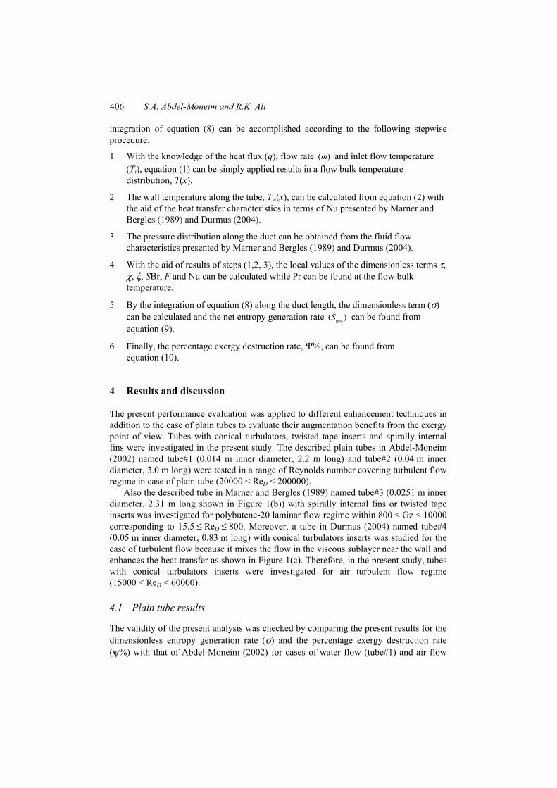
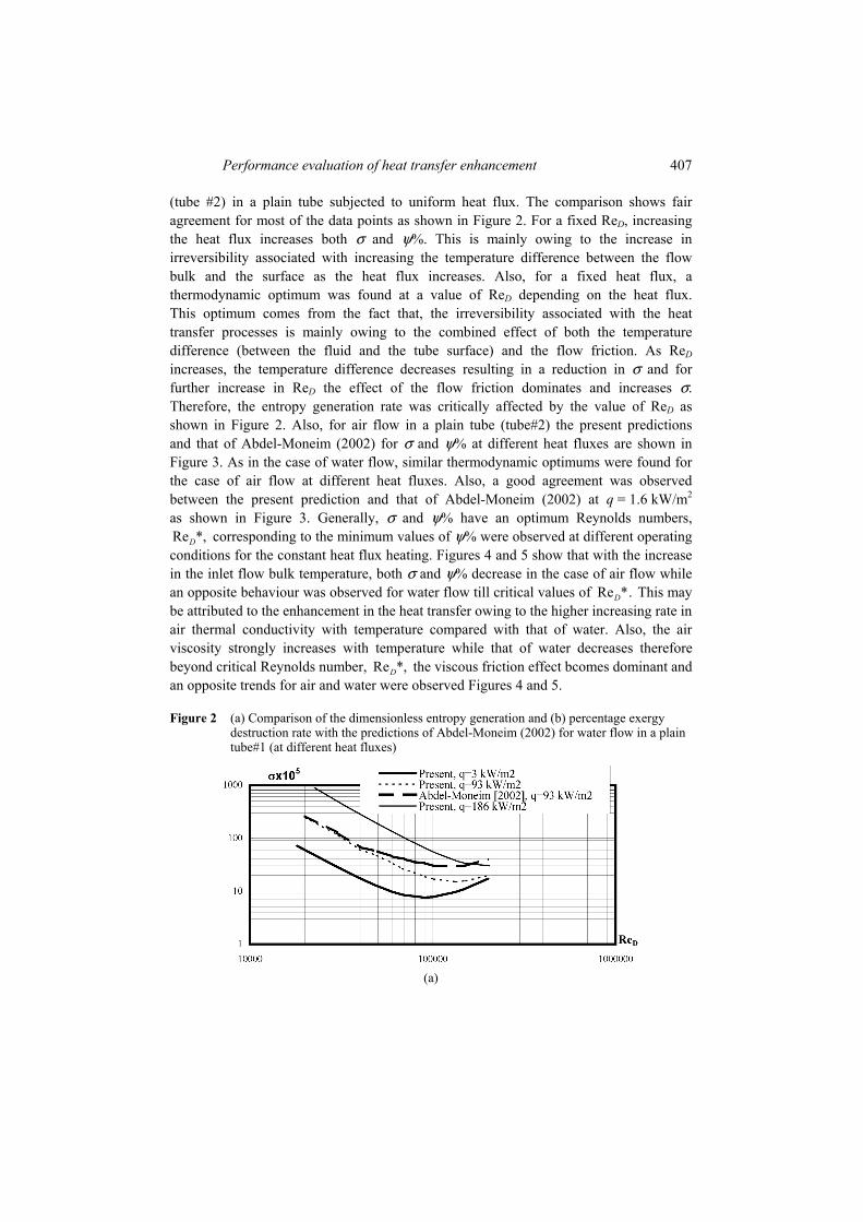
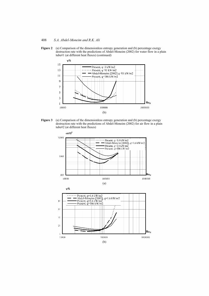
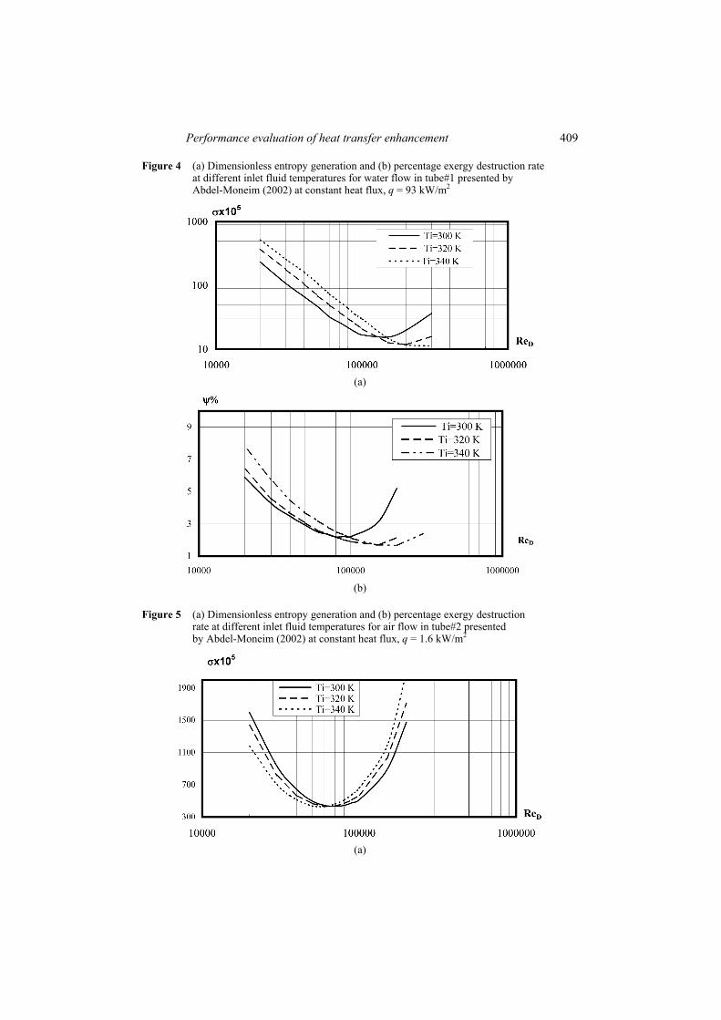
(tube #2) in a plain tube subjected to uniform heat flux. The comparison shows fair agreement for most of the data points as shown in Figure 2. For a fixed ReD, increasing the heat flux increases both σ and ψ%. This is mainly owing to the increase in irreversibility associated with increasing the temperature difference between the flow bulk and the surface as the heat flux increases. Also, for a fixed heat flux, a thermodynamic optimum was found at a value of ReD depending on the heat flux. This optimum comes from the fact that, the irreversibility associated with the heat transfer processes is mainly owing to the combined effect of both the temperature difference (between the fluid and the tube surface) and the flow friction. As ReD increases, the temperature difference decreases resulting in a reduction in σ and for further increase in ReD the effect of the flow friction dominates and increases σ. Therefore, the entropy generation rate was critically affected by the value of ReD as shown in Figure 2. Also, for air flow in a plain tube (tube#2) the present predictions and that of Abdel-Moneim (2002) for σ and ψ% at different heat fluxes are shown in Figure 3. As in the case of water flow, similar thermodynamic optimums were found for the case of air flow at different heat fluxes. Also, a good agreement was observed between the present prediction and that of Abdel-Moneim (2002) at q = 1.6 kW/m2 as shown in Figure 3. Generally, σ and ψ% have an optimum Reynolds numbers, Re *,D corresponding to the minimum values of ψ% were observed at different operating conditions for the constant heat flux heating. Figures 4 and 5 show that with the increase in the inlet flow bulk temperature, both σ and ψ% decrease in the case of air flow while an opposite behaviour was observed for water flow till critical values of Re *.D This may be attributed to the enhancement in the heat transfer owing to the higher increasing rate in air thermal conductivity with temperature compared with that of water. Also, the air viscosity strongly increases with temperature while that of water decreases therefore beyond critical Reynolds number, Re *,D the viscous friction effect bcomes dominant and an opposite trends for air and water were observed Figures 4 and 5.
Figure 2 (a) Comparison of the dimensionless entropy generation and (b) percentage exergy destruction rate with the predictions of Abdel-Moneim (2002) for water flow in a plain tube#1 (at different heat fluxes)
(a)
408 S.A. Abdel-Moneim and R.K. Ali
Figure 2 (a) Comparison of the dimensionless entropy generation and (b) percentage exergy destruction rate with the predictions of Abdel-Moneim (2002) for water flow in a plain tube#1 (at different heat fluxes) (continued)
(b)
Figure 3 (a) Comparison of the dimensionless entropy generation and (b) percentage exergy destruction rate with the predictions of Abdel-Moneim (2002) for air flow in a plain tube#2 (at different heat fluxes)
(a)
(b)
Performance evaluation of heat transfer enhancement 409
Figure 4 (a) Dimensionless entropy generation and (b) percentage exergy destruction rate at different inlet fluid temperatures for water flow in tube#1 presented by Abdel-Moneim (2002) at constant heat flux, q = 93 kW/m2
(a)
(b)
Figure 5 (a) Dimensionless entropy generation and (b) percentage exergy destruction rate at different inlet fluid temperatures for air flow in tube#2 presented by Abdel-Moneim (2002) at constant heat flux, q = 1.6 kW/m2
(a)
410 S.A. Abdel-Moneim and R.K. Ali
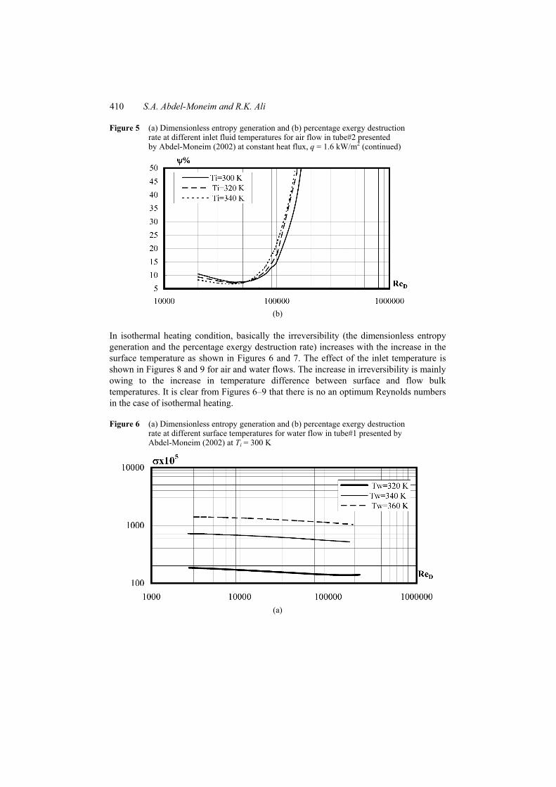
Figure 5 (a) Dimensionless entropy generation and (b) percentage exergy destruction rate at different inlet fluid temperatures for air flow in tube#2 presented by Abdel-Moneim (2002) at constant heat flux, q = 1.6 kW/m2 (continued)
(b)
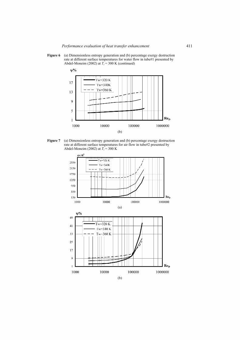
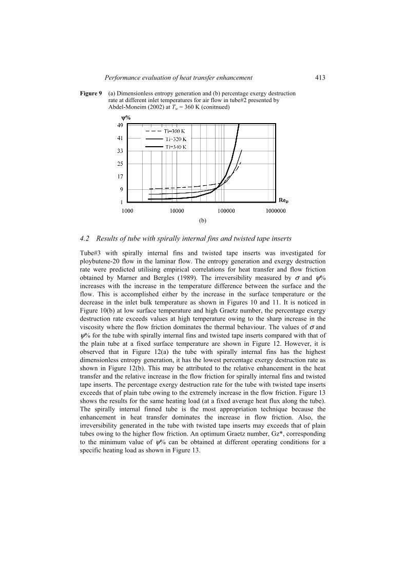
In isothermal heating condition, basically the irreversibility (the dimensionless entropy generation and the percentage exergy destruction rate) increases with the increase in the surface temperature as shown in Figures 6 and 7. The effect of the inlet temperature is shown in Figures 8 and 9 for air and water flows. The increase in irreversibility is mainly owing to the increase in temperature difference between surface and flow bulk temperatures. It is clear from Figures 6–9 that there is no an optimum Reynolds numbers in the case of isothermal heating.
Figure 6 (a) Dimensionless entropy generation and (b) percentage exergy destruction rate at different surface temperatures for water flow in tube#1 presented by Abdel-Moneim (2002) at Ti = 300 K
(a)
Performance evaluation of heat transfer enhancement 411
Figure 6 (a) Dimensionless entropy generation and (b) percentage exergy destruction rate at different surface temperatures for water flow in tube#1 presented by Abdel-Moneim (2002) at Ti = 300 K (continued)
(b)
Figure 7 (a) Dimensionless entropy generation and (b) percentage exergy destruction rate at different surface temperatures for air flow in tube#2 presented by Abdel-Moneim (2002) at Ti = 300 K
(a)
(b)
412 S.A. Abdel-Moneim and R.K. Ali
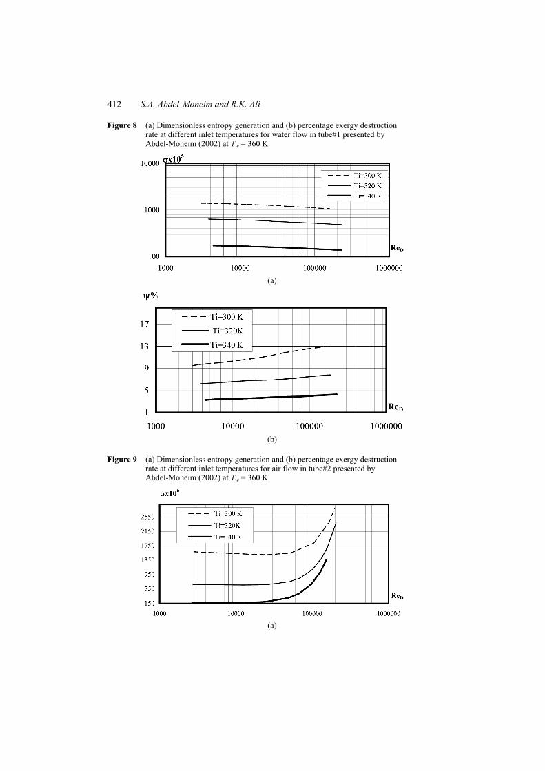
Figure 8 (a) Dimensionless entropy generation and (b) percentage exergy destruction rate at different inlet temperatures for water flow in tube#1 presented by Abdel-Moneim (2002) at Tw = 360 K
(a)
(b)
Figure 9 (a) Dimensionless entropy generation and (b) percentage exergy destruction rate at different inlet temperatures for air flow in tube#2 presented by Abdel-Moneim (2002) at Tw = 360 K
(a)
Performance evaluation of heat transfer enhancement 413
Figure 9 (a) Dimensionless entropy generation and (b) percentage exergy destruction rate at different inlet temperatures for air flow in tube#2 presented by Abdel-Moneim (2002) at Tw = 360 K (conitnued)
(b)
4.2 Results of tube with spirally internal fins and twisted tape inserts
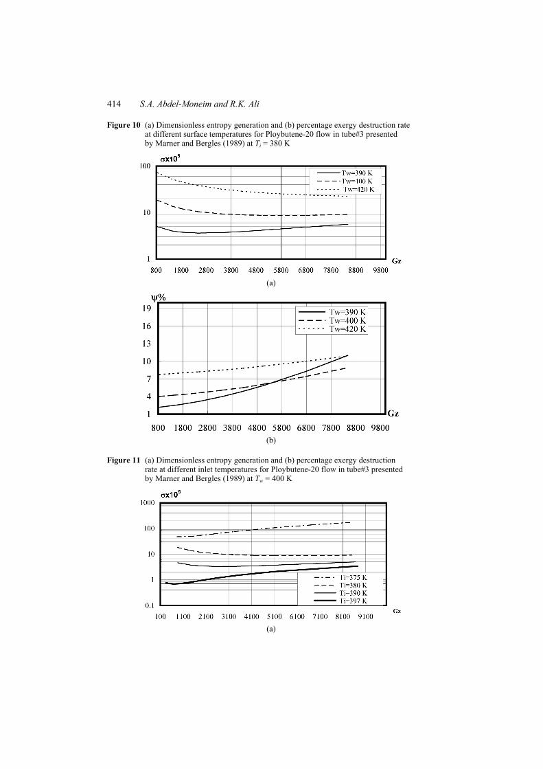
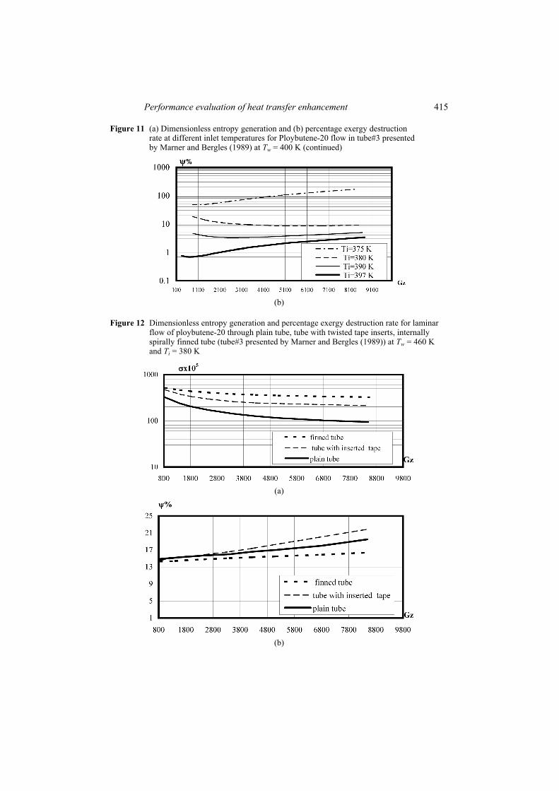
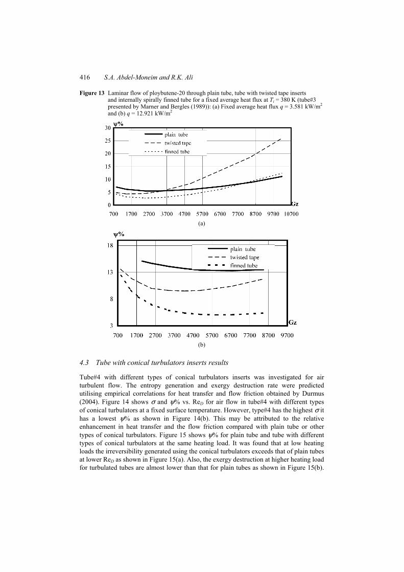
Tube#3 with spirally internal fins and twisted tape inserts was investigated for ploybutene-20 flow in the laminar flow. The entropy generation and exergy destruction rate were predicted utilising empirical correlations for heat transfer and flow friction obtained by Marner and Bergles (1989). The irreversibility measured by σ and ψ% increases with the increase in the temperature difference between the surface and the flow. This is accomplished either by the increase in the surface temperature or the decrease in the inlet bulk temperature as shown in Figures 10 and 11. It is noticed in Figure 10(b) at low surface temperature and high Graetz number, the percentage exergy destruction rate exceeds values at high temperature owing to the sharp increase in the viscosity where the flow friction dominates the thermal behaviour. The values of σ and ψ% for the tube with spirally internal fins and twisted tape inserts compared with that of the plain tube at a fixed surface temperature are shown in Figure 12. However, it is observed that in Figure 12(a) the tube with spirally internal fins has the highest dimensionless entropy generation, it has the lowest percentage exergy destruction rate as shown in Figure 12(b). This may be attributed to the relative enhancement in the heat transfer and the relative increase in the flow friction for spirally internal fins and twisted tape inserts. The percentage exergy destruction rate for the tube with twisted tape inserts exceeds that of plain tube owing to the extremely increase in the flow friction. Figure 13 shows the results for the same heating load (at a fixed average heat flux along the tube). The spirally internal finned tube is the most appropriation technique because the enhancement in heat transfer dominates the increase in flow friction. Also, the irreversibility generated in the tube with twisted tape inserts may exceeds that of plain tubes owing to the higher flow friction. An optimum Graetz number, Gz*, corresponding to the minimum value of ψ% can be obtained at different operating conditions for a specific heating load as shown in Figure 13.
414 S.A. Abdel-Moneim and R.K. Ali
Figure 10 (a) Dimensionless entropy generation and (b) percentage exergy destruction rate at different surface temperatures for Ploybutene-20 flow in tube#3 presented by Marner and Bergles (1989) at Ti = 380 K
(a)
(b)
Figure 11 (a) Dimensionless entropy generation and (b) percentage exergy destruction rate at different inlet temperatures for Ploybutene-20 flow in tube#3 presented by Marner and Bergles (1989) at Tw = 400 K
(a)
Performance evaluation of heat transfer enhancement 415
Figure 11 (a) Dimensionless entropy generation and (b) percentage exergy destruction rate at different inlet temperatures for Ploybutene-20 flow in tube#3 presented by Marner and Bergles (1989) at Tw = 400 K (continued)
(b)
Figure 12 Dimensionless entropy generation and percentage exergy destruction rate for laminar flow of ploybutene-20 through plain tube, tube with twisted tape inserts, internally spirally finned tube (tube#3 presented by Marner and Bergles (1989)) at Tw = 460 K and Ti = 380 K
(a)
(b)
416 S.A. Abdel-Moneim and R.K. Ali
Figure 13 Laminar flow of ploybutene-20 through plain tube, tube with twisted tape inserts and internally spirally finned tube for a fixed average heat flux at Ti = 380 K (tube#3 presented by Marner and Bergles (1989)): (a) Fixed average heat flux q = 3.581 kW/m2 and (b) q = 12.921 kW/m2
(a)
(b)
4.3 Tube with conical turbulators inserts results
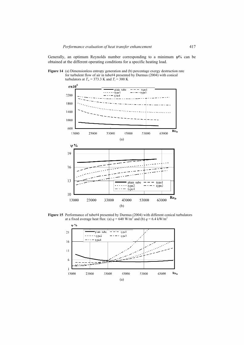
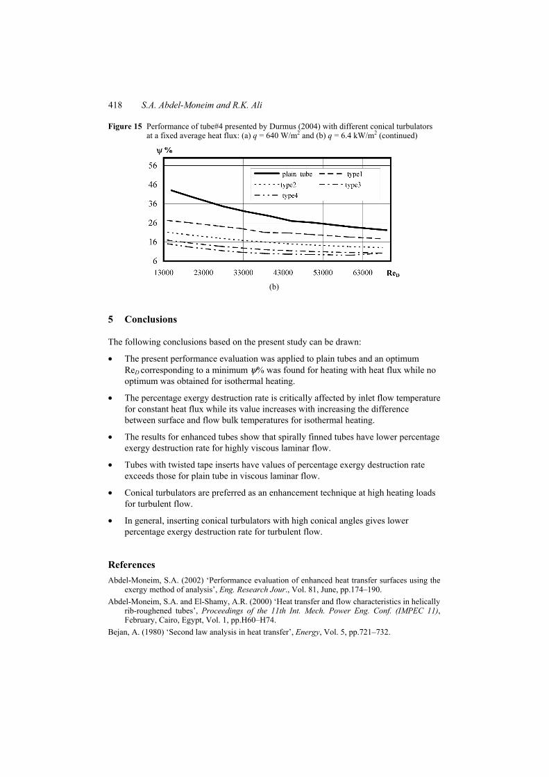
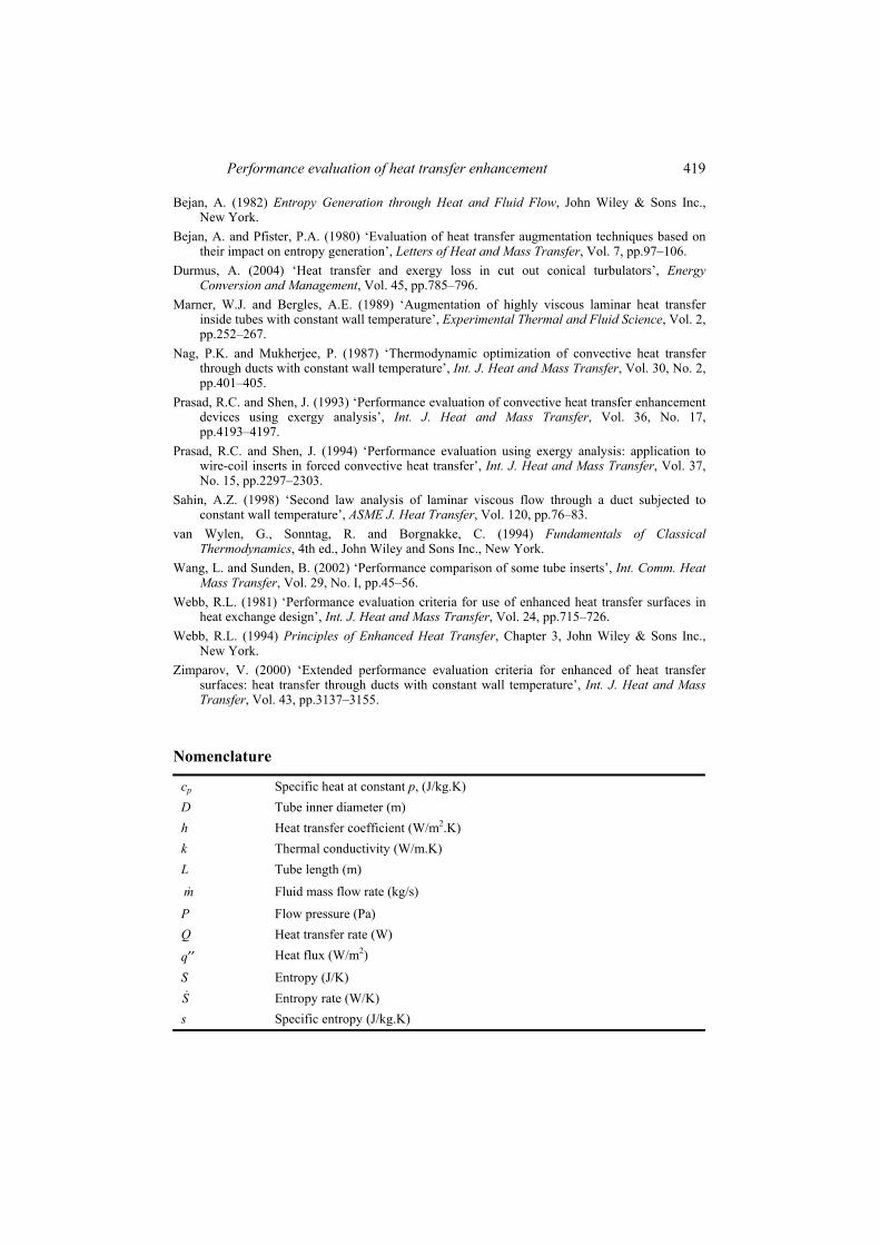
Tube#4 with different types of conical turbulators inserts was investigated for air turbulent flow. The entropy generation and exergy destruction rate were predicted utilising empirical correlations for heat transfer and flow friction obtained by Durmus (2004). Figure 14 shows σ and ψ% vs. ReD for air flow in tube#4 with different types of conical turbulators at a fixed surface temperature. However, type#4 has the highest σ it has a lowest ψ% as shown in Figure 14(b). This may be attributed to the relative enhancement in heat transfer and the flow friction compared with plain tube or other types of conical turbulators. Figure 15 shows ψ% for plain tube and tube with different types of conical turbulators at the same heating load. It was found that at low heating loads the irreversibility generated using the conical turbulators exceeds that of plain tubes at lower ReD as shown in Figure 15(a). Also, the exergy destruction at higher heating load for turbulated tubes are almost lower than that for plain tubes as shown in Figure 15(b).
Performance evaluation of heat transfer enhancement 417
Generally, an optimum Reynolds number corresponding to a minimum ψ% can be obtained at the different operating conditions for a specific heating load.
Figure 14 (a) Dimensionless entropy generation and (b) percentage exergy destruction rate for turbulent flow of air in tube#4 presented by Durmus (2004) with conical turbulators at Tw = 373.3 K and Ti = 300 K
(a)
(b)
Figure 15 Performance of tube#4 presented by Durmus (2004) with different conical turbulators at a fixed average heat flux: (a) q = 640 W/m2 and (b) q = 6.4 kW/m2
(a)
418 S.A. Abdel-Moneim and R.K. Ali
Figure 15 Performance of tube#4 presented by Durmus (2004) with different conical turbulators at a fixed average heat flux: (a) q = 640 W/m2 and (b) q = 6.4 kW/m2 (continued)
(b)
5 Conclusions
The following conclusions based on the present study can be drawn:
• The present performance evaluation was applied to plain tubes and an optimum ReD corresponding to a minimum ψ% was found for heating with heat flux while no optimum was obtained for isothermal heating.
• The percentage exergy destruction rate is critically affected by inlet flow temperature for constant heat flux while its value increases with increasing the difference between surface and flow bulk temperatures for isothermal heating.
• The results for enhanced tubes show that spirally finned tubes have lower percentage exergy destruction rate for highly viscous laminar flow.
• Tubes with twisted tape inserts have values of percentage exergy destruction rate exceeds those for plain tube in viscous laminar flow.
• Conical turbulators are preferred as an enhancement technique at high heating loads for turbulent flow.
• In general, inserting conical turbulators with high conical angles gives lower percentage exergy destruction rate for turbulent flow.
References Abdel-Moneim, S.A. (2002) ‘Performance evaluation of enhanced heat transfer surfaces using the
exergy method of analysis’, Eng. Research Jour., Vol. 81, June, pp.174–190. Abdel-Moneim, S.A. and El-Shamy, A.R. (2000) ‘Heat transfer and flow characteristics in helically
rib-roughened tubes’, Proceedings of the 11th Int. Mech. Power Eng. Conf. (IMPEC 11), February, Cairo, Egypt, Vol. 1, pp.H60–H74.
Bejan, A. (1980) ‘Second law analysis in heat transfer’, Energy, Vol. 5, pp.721–732.
Performance evaluation of heat transfer enhancement 419
Bejan, A. (1982) Entropy Generation through Heat and Fluid Flow, John Wiley & Sons Inc., New York.
Bejan, A. and Pfister, P.A. (1980) ‘Evaluation of heat transfer augmentation techniques based on their impact on entropy generation’, Letters of Heat and Mass Transfer, Vol. 7, pp.97–106.
Durmus, A. (2004) ‘Heat transfer and exergy loss in cut out conical turbulators’, Energy Conversion and Management, Vol. 45, pp.785–796.
Marner, W.J. and Bergles, A.E. (1989) ‘Augmentation of highly viscous laminar heat transfer inside tubes with constant wall temperature’, Experimental Thermal and Fluid Science, Vol. 2, pp.252–267.
Nag, P.K. and Mukherjee, P. (1987) ‘Thermodynamic optimization of convective heat transfer through ducts with constant wall temperature’, Int. J. Heat and Mass Transfer, Vol. 30, No. 2, pp.401–405.
Prasad, R.C. and Shen, J. (1993) ‘Performance evaluation of convective heat transfer enhancement devices using exergy analysis’, Int. J. Heat and Mass Transfer, Vol. 36, No. 17, pp.4193–4197.
Prasad, R.C. and Shen, J. (1994) ‘Performance evaluation using exergy analysis: application to wire-coil inserts in forced convective heat transfer’, Int. J. Heat and Mass Transfer, Vol. 37, No. 15, pp.2297–2303.
Sahin, A.Z. (1998) ‘Second law analysis of laminar viscous flow through a duct subjected to constant wall temperature’, ASME J. Heat Transfer, Vol. 120, pp.76–83.
van Wylen, G., Sonntag, R. and Borgnakke, C. (1994) Fundamentals of Classical Thermodynamics, 4th ed., John Wiley and Sons Inc., New York.
Wang, L. and Sunden, B. (2002) ‘Performance comparison of some tube inserts’, Int. Comm. Heat Mass Transfer, Vol. 29, No. I, pp.45–56.
Webb, R.L. (1981) ‘Performance evaluation criteria for use of enhanced heat transfer surfaces in heat exchange design’, Int. J. Heat and Mass Transfer, Vol. 24, pp.715–726.
Webb, R.L. (1994) Principles of Enhanced Heat Transfer, Chapter 3, John Wiley & Sons Inc., New York.
Zimparov, V. (2000) ‘Extended performance evaluation criteria for enhanced of heat transfer surfaces: heat transfer through ducts with constant wall temperature’, Int. J. Heat and Mass Transfer, Vol. 43, pp.3137–3155.
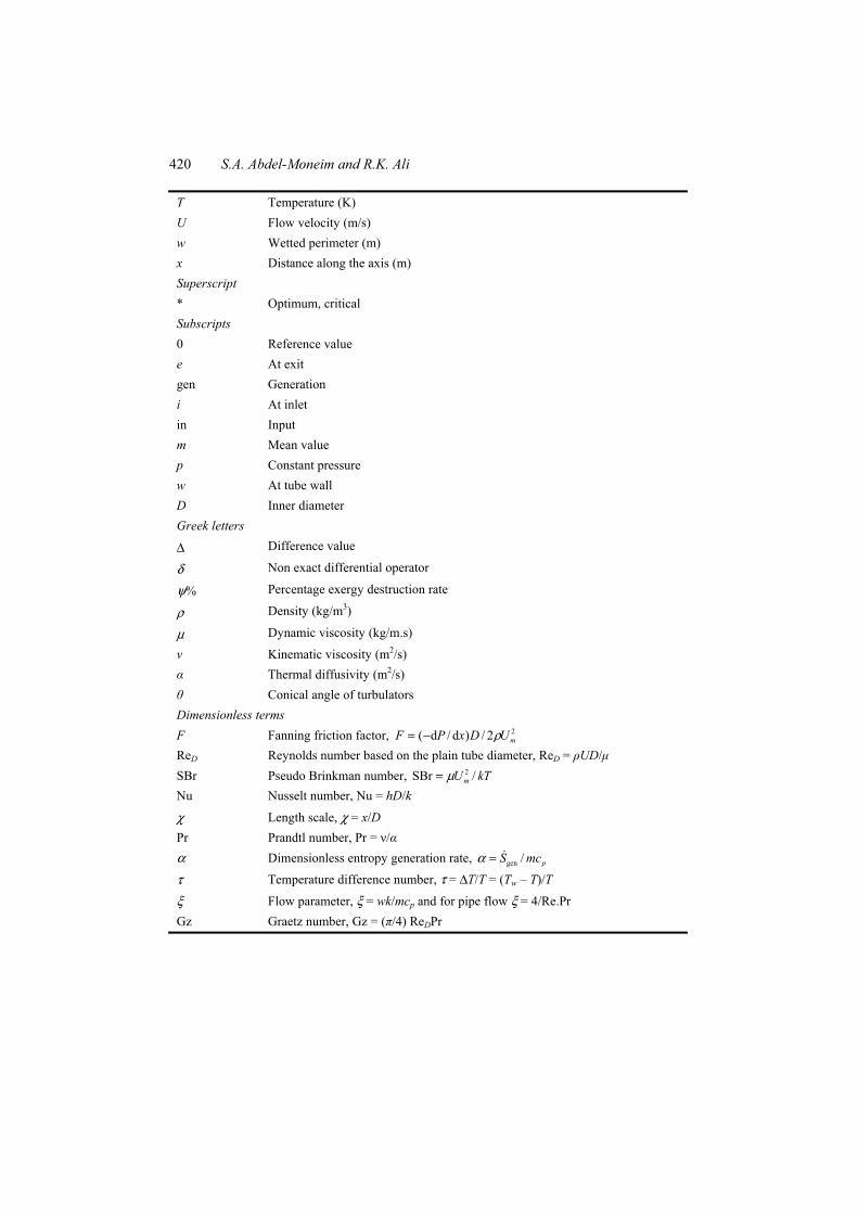
Nomenclature
cp Specific heat at constant p, (J/kg.K) D Tube inner diameter (m) h Heat transfer coefficient (W/m2.K) k Thermal conductivity (W/m.K) L Tube length (m)
m Fluid mass flow rate (kg/s)
P Flow pressure (Pa) Q Heat transfer rate (W)
q′′ Heat flux (W/m2)
S Entropy (J/K) S Entropy rate (W/K) s Specific entropy (J/kg.K)
420 S.A. Abdel-Moneim and R.K. Ali
T Temperature (K) U Flow velocity (m/s) w Wetted perimeter (m) x Distance along the axis (m) Superscript * Optimum, critical Subscripts 0 Reference value e At exit gen Generation i At inlet in Input m Mean value p Constant pressure w At tube wall D Inner diameter Greek letters
∆ Difference value
δ Non exact differential operator
ψ% Percentage exergy destruction rate
ρ Density (kg/m3)
µ Dynamic viscosity (kg/m.s)
ν Kinematic viscosity (m2/s) α Thermal diffusivity (m2/s) θ Conical angle of turbulators Dimensionless terms F Fanning friction factor, 2( d / d ) / 2 mF P x D Uρ= − ReD Reynolds number based on the plain tube diameter, ReD = ρUD/µ SBr Pseudo Brinkman number, 2SBr /mU kTµ= Nu Nusselt number, Nu = hD/k
χ Length scale, χ = x/D Pr Prandtl number, Pr = ν/α α Dimensionless entropy generation rate, gen / pS mcα =
τ Temperature difference number, τ = ∆T/T = (Tw – T)/T
ξ Flow parameter, ξ = wk/mcp and for pipe flow ξ = 4/Re.Pr Gz Graetz number, Gz = (π/4) ReDPr